1
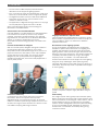
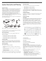
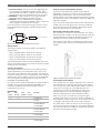
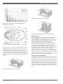
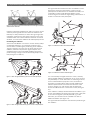
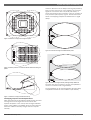
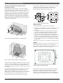
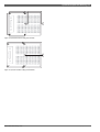
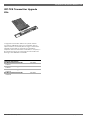
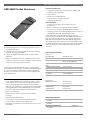
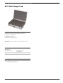
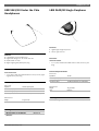
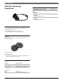
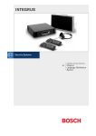
Bosch Integrus
Data Brochure
Table of Contents
Introduction
1
System Description and Planning
5
System Specification
15
Transmitters and Interface Modules
17
INT-TX Transmitters
INT-TXK Transmitter Upgrade Kits
LBB 3422/20 Symmetrical Audio Input and Interpreter
Module
DCN-FCCCU Flight Case for 2 Central Control Units
17
19
20
21
Infra-red Radiators
23
LBB 451x/00 Infra-red Radiators
INT-FCRAD Flight Case for Radiator
LBB 3414/00 Wall Mounting Bracket
LBC 1259/00 Universal Floorstand
LBB 3410/05 Infra-red Radiator
23
25
25
26
28
Infra-red Receivers, Charging Units and Accessories
29
LBB 4540 Pocket Receivers
LBB 4550/00 NiMH Battery Pack
LBB 4560 Charging Units
INT-FCRX Storage Case
29
30
31
32
Headphones
33
LBB 3441/10 Under the Chin Headphones
LBB 3442/00 Single Earphone
LBB 3443 Lightweight Headphones
LBB 3015/04 High Quality Dynamic Headphones
HDP-ILN Induction Loop Neckband
33
33
34
35
35
Interpreter Desk and Accessories
37
LBB 3222/04 Interpreter Desk
LBB 3306 Extension Cables
LBB 9095/30 Interpreter Headphones
37
38
38
www.boschsecurity.com
Bosch Security Systems B.V.
Bosch Security Systems B.V.
www.boschsecurity.com
Introduction | 1
Introduction
Introduction
Simultaneous Interpretation
The transmitter is the central element in the Integrus
system. It accepts inputs from either analog or digital
sources, modulates these signals on to carrier waves, then
transmits the waves to infra-red radiators located elsewhere
in the room. The transmitter accommodates special
interface modules to ensure compatibility with these
external signal sources. Depending on the transmitter
model, up to 32 separate channels can be transmitted
simultaneously.
Introduction
For international conferences with multiple languages, it is
obviously of utmost importance that all participants can
understand what is being said. That is why a system which
enables interpreters to simultaneously interpret the
speaker’s language is almost indispensable. The
interpretations created are then distributed throughout the
conference venue, so delegates can select their language of
choice and listen to it through headphones.
Infra-Red Distribution
The most effective method of distributing the
interpretations is by using an infra-red language distribution
system. Infra-red means wireless, so delegates have total
freedom of movement. It means information integrity,
because distributed signals cannot pass beyond the
conference hall. And now, with the Bosch Integrus system, it
means better than ever audio quality, with no interference
from hall lighting.
In simple terms, an infra-red distribution system consists of
a transmitter, one or more radiators and a number of
receivers. Various accessories are also available, such as
headphones, cables and battery chargers.
www.boschsecurity.com
The output of the infra-red radiators is intensity-modulated
infra-red radiation. Each delegate is supplied with a pocket
receiver, which has a lens to collect the infra-red signal and
direct it to a sensor. These signals are then decoded back
into interpretation languages, which are chosen by
delegates using a channel selector and passed to the
delegate’s headphones.
Advanced Digital Technology
The Integrus language distribution system incorporates
unique, specially-developed Bosch Ir-Digital technology that
is characterized by a number of features:
• The Integrus conforms to IEC 61603, part 7. This is the
industry standard for digital infra-red transmission for
language distribution
Bosch Security Systems B.V.
2 | Introduction
• The use of the 2-8 MHz frequency band eliminates
disturbance from all types of lighting systems
• Error correction by means of a Reed Solomon coder, plus
the bit error rate threshold, ensures a high audio quality
• The digital transmission protocol used allows additional
information to be sent (e.g. synchronization of the
number of channels in use)
• The application of digital technology results in a very high
sound quality with a signal/noise ratio of 80 dB
Some of the advantages of this new technology are
described in more detail below.
Characteristics of Infra-red Distribution
Infra-red radiation is an ideal medium for audio distribution.
It is invisible to the human eye and can carry multiple
channels, each with a separate language, over relatively
large distances. And, above all, it is a wireless distribution
system, so conference participants can receive
interpretations without being physically connected to the
system.
Freedom of Movement for Delegates
With an infra-red system, delegates have great freedom in
movement throughout the conference room. As the
interpretations are transmitted through the air, there is no
physical connection to the system, so the only limitations
are the walls of the venue itself. The receivers used by
delegates to pick up interpretations are lightweight,
portable and unobtrusive, and can be easily slipped into a
shirt or jacket pocket.
Language Distribution in Adjacent Halls
Infra-red systems are ideally-suited for conference centers
with a number of separate halls. Since walls are opaque to
infra-red radiation, there is no interference between
separate conferences.
No Interference from Lighting Systems
One of the limitations of traditional infra-red language
distribution systems was interference from lighting. The
problem was particularly acute with newer (fluorescent)
lighting systems, which operate at higher frequencies and
therefore cause more interference. The Integrus system has
completely solved this problem by using a much higher
frequency band – 2 to 8 MHz – for audio distribution.
Freedom from interference from all types of venue lighting
brings two major advantages: audio quality is greatly
improved, and systems can be used much more easily on a
rental basis, because they will be compatible with all types
of venue lighting.
Distorted reception (left) with other language distribution
systems, and perfect reception (right) with Bosch Integrus
system
Conference Hall Privacy
Audio Quality
Conferences can often involve discussion of sensitive
information, where it is important that any audio
distribution does not compromise security. As infra-red
radiation is unable to pass through opaque structures such
as walls, the congress venue itself acts as a barrier to infrared radiation escaping and being overheard.
The Integrus system offers greatly improved audio quality.
Better compression techniques and a higher signal-to-noise
ratio means that the received signal is much clearer, and, as
mentioned above, there is no interference from lighting
systems. Greater intelligibility makes the system less tiring
to use over extended periods. Delegates can therefore
maintain their concentration more easily during a long
conference session.
Bosch Security Systems B.V.
www.boschsecurity.com
Introduction | 3
Number of Channels
Testing Coverage
The Integrus gives the user real flexibility in choosing the
number of required channels. By using a much higher
frequency band (2 to 8 MHz) it offers four quality modes:
The Integrus receivers have an ingenious feature, which
allows installers to test the coverage of infra-red radiators
without the need for measuring equipment. Simply by
walking throughout the venue holding a receiver in
measuring mode, it is possible to check the coverage at
every point. This makes it easy to see whether extra
radiators are required or if the positioning of existing ones
should be altered.
• Standard-quality mono (for interpretations). Four
channels of this quality can be incorporated in a single
carrier signal
• Standard quality stereo (for reproduction of music or
presentations). Two channels of this quality can be
incorporated in a single carrier signal
• Premium-quality mono (with double the bandwidth). Two
channels of this quality can be incorporated in a single
carrier signal
• Premium-quality stereo (for excellent reproduction of
music or presentations). One channel of this quality can
be incorporated in a single carrier signal
The Integrus can therefore provide a maximum of 32
standard-quality audio channels (which means up to 31
different interpretations + the floor), more than enough to
accommodate even the largest international conferences. It
can also be configured for high quality stereo sound, with
up to eight different channels available for applications like
multimedia presentations or music distribution.
Combinations of standard- and premium-quality
configuration are also possible.
User-Friendly Channel Selection
The Integrus receivers offer the user the exact amount of
channels available. This eliminates having to scroll through
unused channels before reaching the required signal. All
receivers in the system automatically update themselves if
the number of available channels changes.
Installation and Maintenance of the System
The Integrus system is easy to install (installation time is
largely determined by the time required to position and
align the radiators.) Connection of the transmitters is
straightforward and quick. The transmitter has slots for
modules that enable interfacing with digital or analogue
conference systems. All information regarding installation,
configuration and system status is given on the transmitter
front-panel display. The display also shows the menu, which
allows all system parameters to be set or altered. One easyto-use button is all that is required to select all menu
options.
Integrated Charging Electronics
A breakthrough in technology has made receiver charging
more reliable than ever. The process is regulated from the
Integrus system IC, although each receiver now has
integrated electronics to allow it to manage its own charging
process. This ensures optimum charging performance and
maximum battery lifetime.
Room Coupling
For distributing interpretations to multiple rooms, the
Integrus transmitter has a master/slave operation mode.
This means that separate (slave) transmitters can be located
in the other rooms, providing exactly the same functionality
as the master transmitter and providing local outputs for
radiators. This removes the need to connect the radiators
required for the additional rooms to one transmitter, which
cuts the amount of wiring required and eliminates the risk of
capacity overload.
Emergency or Auxiliary Input
To provide delegates with an additional degree of safety and
security, the infra-red transmitter unit includes an additional
auxiliary input which overrides all active audio channels.
This auxiliary input allows the immediate distribution of
emergency messages to all active channels. The auxiliary
input may also be used for the distribution of music or other
information.
Complete Integration
Integrus integrates seamlessly with the DCN Next
Generation and DCN Wireless using an optical network for a
maximum 31 different languages, plus floor. Use Integrus
with CCS 800 Ultro and the analog 6-channel interpreter
desk for perfect reception at smaller meetings. Or easily
interface with virtually any other brand of congress system.
For more information, see the relevant data brochures.
Circuitry in the transmitter and matching circuitry in the
radiators allows effective monitoring of the infra-red
radiator function. The status of the radiators is indicated on
the transmitter display and by LEDs on each radiator. The
system is also easy to maintain. Maintenance of the
receivers generally involves recharging or replacing the
batteries they use.
Once installed, the system can easily be extended to
accommodate more conference delegates, simply by adding
the required number of extra receivers. The basic system
structure will remain the same.
www.boschsecurity.com
Bosch Security Systems B.V.
4 | Introduction
Music Distribution and Hearing Assistance
The Integrus offers more than just language (interpretation)
distribution. Its flexibility and high audio quality also make it
suitable for:
• Music distribution. In places as diverse as fitness centers
and factories, it can provide a choice of music for
listeners in locations throughout the premises
• High-quality audio distribution. Multi-lingual cinemas can
offer different language soundtracks in the same hall
• Hearing assistance. Helps the hard-of-hearing in places
like theatres and other public buildings
• Concert halls and life theaters can distribute the
amplified sound in high quality to the musicians on stage
without interference or risk of feedback
• Distribution of instructions. TV studios can use the
system to distribute instructions from the control gallery
to the camera men without RF interference
• Tour guide. Canal boats and museums can offer their
customers the tour information in their own language
with high audio quality
• Provides musicians on stage the audio they require for
their performance
• Interpretation schools. Distribution of the floor and the
interpretation on respectively the left and right channel
for simultaneous listening to the floor and the selected
interpretation
Bosch Security Systems B.V.
www.boschsecurity.com
System Description and Planning | 5
System Description and Planning
Infra-red receivers
Introduction
• LBB 4540/04 for 4 audio channels
System overview
• LBB 4540/08 for 8 audio channels
Integrus is a system for wireless distribution of audio signals
via infra-red radiation. It can be used in a simultaneous
interpretation system for international conferences where
multiple languages are used. To enable all participants to
understand the proceedings, interpreters simultaneously
translate the speaker’s language as required. These
interpretations are distributed throughout the conference
venue, and delegates select the language of their choice and
listen to it through headphones.
• LBB 4540/32 for 32 audio channels
The Integrus system can also be used for music distribution
(mono as well as stereo).
System technology
System Description and Planning
Three multi-channel infra-red receivers are available:
They can operate with a rechargeable NiMH battery pack or
with disposable batteries. Charging circuitry is incorporated
in the receiver.
Charging equipment
Equipment is available for charging and storing 56 infra-red
receivers. It is available for portable or fixed-installation
applications.
IR radiation
The Integrus system is based on transmission by modulated
infra-red radiation. Infra-red radiation forms part of the
electro-magnetic spectrum, which is composed of visible
light, radio waves and other types of radiation. It has a
wavelength just above that of visible light. Like visible light,
it is reflected from hard surfaces, yet passes through
translucent materials such as glass. The infra-red radiation
spectrum in relation to other relevant spectra is shown in
figure 2
Figure 1: Integrus system overview (with DCN system as input)
1
The Integrus Digital Infra-red Language Distribution System
comprises one or more of the following:
Infra-red transmitter
The transmitter is the core of the Integrus system. Four
types are available:
• INT-TX04 with inputs for 4 audio channels
4
2
5
3
Figure 2: Infra-red radiation spectrum in relation to other spectra
• INT-TX08 with inputs for 8 audio channels
• INT-TX16 with inputs for 16 audio channels
• INT-TX32 with inputs for 32 audio channels
Interface module
An LBB 3422/20 Symmetrical Audio Input and Interpreter
Module to connect to analogue discussion and conference
systems (such as CCS 800), or to LBB 3222/04 6-channel
interpreters desks.
Infra-red radiators
(1) Daylight spectrum
(2) Sensitivity of the human eye
(3) IR radiator
(4) Sensitivity of the IR sensor
(5) Sensitivity of the IR sensor with daylight filter
Signal Processing
• LBB 4511/00 medium-power radiator for small / medium
The Integrus system uses high frequency carrier signals
(typically 2 to 8 MHz) to prevent interference problems with
modern light sources (see section ‘Ambient Lighting’). The
digital audio processing guarantees a constant high audio
quality.
• LBB 4512/00 high-power radiator for medium/large
The signal processing in the transmitter consists of the
following main steps (see figure 3):
Three types of radiators available:
• LBB 3410/05 wide beam radiator for small conference
venues
conference venues
conference venues
All three types can be switched between full and half power
use. They can be mounted on walls, ceilings or floor stands.
www.boschsecurity.com
1. A/D conversion -Each analogue audio channel is
converted to a digital signal.
2. Compression - The digital signals are compressed to
increase the amount of information that can be
distributed on each carrier. The compression factor is
also related to the required audio quality.
Bosch Security Systems B.V.
6 | System Description and Planning
3. Protocol Creation - Groups of up to four digital signals
are combined into a digital information stream. Extra
fault algorithm information is added. This information is
used by the receivers for fault detection and correction.
4. Modulation - A high frequency carrier signal is phase
modulated with the digital information stream.
5. Radiation - Up to 8 modulated carrier signals are
combined and sent to the IR radiators, which convert the
carrier signals to modulated infra-red light.
In the IR receivers a reverse processing is used to convert
the modulated infra-red light to separate analogue audio
channels.
Aspects of infra-red distribution systems
A good infra-red distribution system ensures that all
delegates in a conference venue receive the distributed
signals without disturbance. This is achieved by using
enough radiators, placed at well planned positions, so that
the conference venue is covered with uniform IR-radiation of
adequate strength.
There are several aspects that influence the uniformity and
quality of the infra-red signal, which must be considered
when planning an infra-red radiation distribution system.
These are discussed in the next sections.
Directional sensitivity of the receiver
Audio
Channel
4x
Audio
Channel
A/D Conversion
& Compression
Protocol Creation
& Modulation
4x
Carrier (to IR Radiators)
A/D Conversion
& Compression
Figure 3: Overview of the signal processing (for one carrier)
Quality modes
The sensitivity of a receiver is at its best when it is aimed
directly towards a radiator. The axis of maximum sensitivity
is tilted upwards at an angle of 45 degrees (see figure 4).
Rotating the receiver will decrease the sensitivity.
For rotations of less than +/- 45 degrees this effect is not
large, but for larger rotations the sensitivity will decrease
rapidly.
The Integrus system can transmit audio in four different
quality modes:
• Mono, standard quality, maximum 32 channels
• Mono, premium quality, maximum 16 channels
• Stereo, standard quality, maximum 16 channels
• Stereo, premium quality, maximum 8 channels
The standard quality mode uses less bandwidth and can be
used for transmitting speech. For music the premium quality
mode gives near CD quality.
Carriers and channels
The Integrus system can transmit up to 8 different carrier
signals (depending on the transmitter type). Each carrier
can contain up to 4 different audio channels. The maximum
number of channels per carrier is dependent on the selected
quality modes. Stereo signals use twice as much bandwidth
as a mono signals, premium quality uses twice as much
bandwidth as standard quality.
Per carrier a mix of channels with different quality modes is
possible, as long as the total available bandwidth is not
exceeded. The table below lists all possible channel
combinations per carrier:
Channel Quality
Mono
Mono
Standard Premium
4
2
1
2
Stereo
Standard
1
1
1
2
2
Stereo
Bandwidth
Premium
4 x 10 kHz
2 x 10 kHz and
1 x 10 kHz
2 x 10 kHz and
1 x 10 kHz (left) and
1 x 10 kHz (right)
1 x 20 kHz and
1 x 10 kHz (left) and
1 x 10 kHz (right)
2 x 20 kHz (left) and
2 x 10 kHz (right)
2 x 20 kHz
1
1 x 20 kHz (left) and
1 x 10 kHz (right)
Bosch Security Systems B.V.
Figure 4: Directional characteristics of the receivers
The footprint of the radiator
The coverage area of a radiator depends on the number of
transmitted carriers and the output power of the radiator.
The coverage area of the LBB 4512/00 radiator is twice as
large as the coverage area of the LBB 4511/00. The
coverage area can also be doubled by mounting two
radiators side by side. The total radiation energy of a
radiator is distributed over the transmitted carriers.
When more carriers are used, the coverage area gets
proportionally smaller. The receiver requires a strength of
the IR signal of 4 mW/m2 per carrier to work without errors
(resulting in a 80 dB S/N ratio for the audio channels).
The effect of the number of carriers on the coverage area
can be seen in figure 5 and figure 6. The radiation pattern is
the area within which the radiation intensity is at least the
minimum required signal strength.
www.boschsecurity.com
System Description and Planning | 7
LBB 4512/00
LBB 4511/00
LBB 3410/05
Figure 8: The radiator mounted at 45° to the ceiling
Figure 5: Total coverage area of LBB 4511/00, LBB 4512/00 and
LBB 3410/05 for 1 to 8 carriers
1
2
4
8
Figure 9: The radiator mounted perpendicular (at 90°) to the ceiling
Ambient lighting
Figure 6: Polar diagram of the radiation pattern for 1, 2, 4 and 8 carriers
The cross section of the 3-dimensional radiation pattern
with the floor of the conference venue is known as the
footprint (the white area in figure 7 to figure 9). This is the
floor area in which the direct signal is strong enough to
ensure proper reception, when the receiver is directed
towards the radiator. As shown, the size and position of the
footprint depends on the mounting height and angle of the
radiator.
The Integrus system is practically immune for the effect of
ambient lighting. Fluorescent lamps (with or without
electronic ballast or dimming facility), such as TL lamps or
energy saving lamps give no problems with the Integrus
system. Also sunlight and artificial lighting with
incandescent or halogen lamps up to 1000 lux give no
problems with the Integrus system. When high levels of
artificial lighting with incandescent or halogen lamps, such
as spotlights or stage lighting are applied, you should
directly point a radiator at the receivers in order to ensure
reliable transmission. For venues containing large,
unscreened windows, you must plan on using additional
radiators. For events taking place in the open air a site test
will be required in order to determine the required amount
of radiators. With sufficient radiators installed, the receivers
will work without errors, even in bright sunlight.
Objects, surfaces and reflections
The presence of objects in a conference venue can influence
the distribution of infra-red light. The texture and color of
the objects, walls and ceilings also plays an important role.
Infra-red radiation is reflected from almost all surfaces. As is
the case with visible light, smooth, bright or shiny surfaces
reflect well. Dark or rough surfaces absorb large proportions
of the infra-red signal (see figure 10). With few exceptions it
cannot pass through materials that are opaque to visible
light.
Figure 7: The radiator mounted at 15° to the ceiling
www.boschsecurity.com
Bosch Security Systems B.V.
8 | System Description and Planning
The figures below illustrate how infra-red radiation can be
directed to conference participants. In figure 13, the
participant is situated clear from obstacles and walls, so a
combination of direct and diffused radiation can be
received. Figure 14 shows the signal being reflected from a
number of surfaces to the participant.
Figure 10: The texture of the material determines how much light is reflected
and how much is absorbed
Problems caused by shadows from walls or furniture can be
solved by ensuring that there are sufficient radiators and
that they are well positioned, so that a strong enough infrared field is produced over the whole conference area. Care
should be taken not to direct radiators towards uncovered
windows, as most of this radiation will subsequently be lost.
Positioning the radiators
Since infra-red radiation can reach a receiver directly and/or
via diffused reflections, it is important to take this into
account when considering the positioning of the radiators.
Though it is best if receivers pick up direct path infra-red
radiation, reflections improve the signal reception and
should therefore not be minimized. Radiators should be
positioned high enough not to be blocked by people in the
hall (see figures 11 and 12).
Figure 13: Combination of direct and reflected radiation
Figure 14: Combination of several reflected signals
Figure 11: Infra-red signal blocked by a person in front of the participant
For concentrically arranged conference rooms, centrally
placed, angled radiators located high up can cover the area
very efficiently. In rooms with few or no reflecting surfaces,
such as a darkened film-projection room, the audience
should be covered by direct path infra-red radiation from
radiators positioned in front. When the direction of the
receiver changes, e.g. with varying seat arrangements,
mount the radiators in the corners of the room (see figure
15).
If the audience is always directed towards the radiators, you
do not need radiators at the back (see figure 16). If the path
of the infra-red signals is partially blocked, e.g. under
balconies, you should cover the ‘shaded’ area with an
additional radiator (see figure 17).
The figures below illustrate the most effective positioning of
the radiators:
Figure 12: Infra-red signal not blocked by a person in front of the participant
Bosch Security Systems B.V.
www.boschsecurity.com
System Description and Planning | 9
However, differences in the delays of the signals picked up
by the receiver from two or more radiators can cause the
signals to cancel each other out (multi path effect). In
worst-case situations this can lead to a loss of reception at
such positions (black spots). Figures 18 and 19 show the
effect of overlapping footprints and differences in signal
delays.
Figure 15: Radiators covering seats arranged in a square
Figure 18: Increased coverage from added radiation power
Figure 16: Radiator position in a conference hall with auditorium seating and
podium
Figure 19: Reduced coverage caused by cable signal delay differences
The lower the carrier frequency, the less susceptible the
receiver is for differences in signal delays.
The signal delays can be compensated by using the delay
compensation switches on the radiators (see manual).
Figure 17: Radiators covering seats beneath a balcony
Overlapping footprints and multipath effects
When the footprints of two radiators partly overlap, the total
coverage area can be larger than the sum of the two
separate footprints. In the overlap area the signal radiation
power of two radiators are added, which increases the area
where the radiation intensity is larger than the required
intensity.
www.boschsecurity.com
Bosch Security Systems B.V.
10 | System Description and Planning
Determining the optimal number of infra-red radiators
required to give 100% coverage of a hall can normally only
be done by performing a site test. However, a good
estimation can be made by using ‘guaranteed rectangular
footprints’. Figures 20 and 21 show what is meant by a
rectangular footprint. As can be seen, the rectangular
footprint is smaller than the total footprint. Note that in
figure 21 the ‘offset’ X is negative because the radiator is
actually mounted beyond the horizontal point at which the
rectangular footprint starts.
Generally (for systems with up to 4 carriers) if the receiver
can pick up the signal of two adjacent radiators, the
distance between these radiators can be increased
approximately by a factor 2.4 (see figure 22).
R1
R2
R3
R4
R1
R2
R3
R4
1.4 W
Rectangular footprints
W
Planning an Integrus infra-red radiation system
L
1.4 L
Figure 22: The effect of overlapping footprints
Planning radiators
Use the following procedure to plan the radiators:
H
W
X
L
Figure 20: Typical rectangular footprint for a 15° mounting angle
1. Follow the recommendations in section ‘Aspects of infrared distribution systems’ to determine the radiator
positions.
2. Look up (in the table) or calculate (with the footprint
calculation tool) the applicable rectangular footprints.
3. Draw the rectangular footprints in the room lay-out.
4. If the receiver can pick up the signal of two adjacent
radiators in some areas, determine the overlap effect and
draw the footprint enlargement(s) in the room lay-out.
5. Check if you have sufficient coverage with the radiators
at the intended positions. If not, add additional radiators
to the room.
See figures 15, 16 and 17 for examples of a radiator lay-out.
Cabling
Signal delay differences can occur due to differences in the
cable length from the transmitter to each radiator. To
minimize the risk of black spots use equal cable length from
transmitter to radiator if possible (see figure 23).
50m
50m
50m
Figure 21: Typical rectangular footprint for a 90° mounting angle
50m
The guaranteed rectangular footprints for various numbers
of carriers, mounting heights and mounting angles can be
found in the section ‘Guaranteed rectangular footprints’.
The height is the distance from the reception plane and not
from the floor.
Guaranteed rectangular footprints can also be calculated
with the footprint calculation tool (available on the
documentation CD-ROM). The given values are for one
radiator only, and therefore do not take into consideration
the beneficial effects of overlapping footprints. The
beneficial effects of reflections are also not included.
Bosch Security Systems B.V.
Figure 23: Radiators with equal cable length
When radiators are loop-through connected, the cabling
between each radiator and the transmitter should be as
symmetrical as possible (see figures 24 and 25). The
differences in cable signal delays can be compensated with
the signal delay compensation switches on the radiators.
www.boschsecurity.com
System Description and Planning | 11
Figure 24: Asymmetrical radiator cabling (to be avoided)
Figure 25: Symmetrical radiator cabling (recommended)
www.boschsecurity.com
Bosch Security Systems B.V.
12 | System Description and Planning
LBB 3410/05
LBB 4511/00
at full power
at full power
LBB 4512/00
at full power
number
mounting
mounting
area
length
width
offset
area
length
width
offset
area
length
width
of
height
angle
A
L
W
X
A
L
W
X
A
L
W
X
carriers
[m]
[degrees]
[m²]
[m]
[m]
[m]
[m²]
[m]
[m]
[m]
[m²]
[m]
[m]
[m]
1
2.5
0
130
13
10
4
627
33
19
7
1269
47
27
10
5
15
130
13
10
4
620
31
20
7
1196
46
26
8
30
140
14
10
3
468
26
18
4
816
34
24
6
45
120
12
10
3
288
18
16
2
480
24
20
2
60
100
10
10
1
196
14
14
0
324
18
18
0
90
56
7
8
-4
144
12
12
-6
196
14
14
-7
589
31
19
9
1288
46
28
10
30
72
9
8
7
551
29
19
5
988
38
26
6
45
90
9
10
4
414
23
18
2
672
28
24
2
60
108
12
9
0
306
18
17
-1
506
23
22
-1
90
80
8
10
-5
10
20
15
256
16
16
-8
400
20
20
-10
30
408
24
17
13
1080
40
27
11
45
368
23
16
7
945
35
27
4
60
418
22
19
1
754
29
26
-1
-13
90
2
324
18
18
-9
676
26
26
2.5
15
63
9
7
2
308
22
14
4
576
32
18
6
5
15
63
9
7
3
322
23
14
5
620
31
20
7
30
56
8
7
3
247
19
13
3
468
26
18
4
45
49
7
7
1
168
14
12
1
288
18
16
2
60
49
7
7
0
132
12
11
-1
196
14
14
0
90
42
6
7
-3
100
10
10
-5
144
12
12
-6
30
266
19
14
6
551
29
19
5
45
234
18
13
2
414
23
18
2
195
15
13
-1
306
18
17
-1
-8
10
20
4
60
30
5
6
2
90
42
6
7
-3
144
12
12
-6
256
16
16
60
195
15
13
3
418
22
19
1
90
196
14
14
-7
324
18
18
-9
2.5
15
160
16
10
3
308
22
14
4
5
15
144
16
9
4
322
23
14
5
10
20
8
offset
20
5
4
2
30
140
14
10
3
247
19
13
3
45
99
11
9
1
168
14
12
1
60
90
10
9
-1
132
12
11
-1
90
64
8
8
-4
100
10
10
-5
45
120
12
10
3
234
18
13
2
60
108
12
9
0
195
15
13
-1
90
100
10
10
-5
144
12
12
-6
90
64
8
8
-4
196
14
14
-7
2.5
15
84
12
7
2
160
16
10
3
5
15
60
10
6
4
144
16
9
4
30
70
10
7
3
140
14
10
3
45
63
9
7
1
99
11
9
1
60
49
7
7
0
90
10
9
-1
90
36
6
6
-3
64
8
8
-4
60
49
7
7
2
108
12
9
0
90
49
7
7
-3.5
100
10
10
-5
10
Guaranteed rectangular footprints (shown in metric units)
Note:
The mounting height is the distance from the
reception plane and not from the floor
Bosch Security Systems B.V.
www.boschsecurity.com
System Description and Planning | 13
LBB 3410/05
LBB 4511/00
at full power
at full power
LBB 4512/00
at full power
number
mounting
mounting
area
length
width
offset
area
length
width
offset
area
length
width
of
height
angle
A
L
W
X
A
L
W
X
A
L
W
X
carriers
[ft]
[degrees]
[ft ²]
[ft]
[ft]
[ft]
[ft ²]
[ft]
[ft]
[ft]
[ft ²]
[ft]
[ft]
[ft]
1
8
0
1419
43
33
13
6696
108
62
23
13706
154
89
33
16
15
1419
43
33
13
6732
102
66
23
12835
151
85
26
30
1518
46
33
10
5015
85
59
13
8848
112
79
20
45
1287
39
33
10
3068
59
52
7
5214
79
66
7
60
1089
33
33
3
2116
46
46
0
3481
59
59
0
90
598
23
26
-13
1521
39
39
- 20
2116
46
46
- 23
6324
102
62
30
13892
151
92
33
30
780
30
26
23
5890
95
62
16
10625
125
85
20
45
990
30
33
13
4425
75
59
7
7268
92
79
7
60
1170
39
30
0
3304
59
56
-3
5400
75
72
-3
90
858
26
33
-16
33
66
15
2704
52
52
- 26
4356
66
66
-33
30
4424
79
56
43
11659
131
89
36
45
3900
75
52
23
10235
115
89
13
60
4464
72
62
3
8075
95
85
-3
- 43
90
2
3481
59
59
- 30
7225
85
85
8
15
690
30
23
7
3312
72
46
13
6195
105
59
20
16
15
690
30
23
10
3450
75
46
16
6732
102
66
23
30
598
26
23
10
2666
62
43
10
5015
85
59
13
45
529
23
23
3
1794
46
39
3
3068
59
52
7
60
529
23
23
0
1404
39
36
-3
2116
46
46
0
90
460
20
23
-10
1089
33
33
-16
1521
39
39
-20
30
2852
62
46
20
5890
95
62
16
45
2537
59
43
7
4425
75
59
7
2107
49
43
-3
3304
59
56
-3
-26
33
66
4
60
320
16
20
7
90
460
20
23
-10
1521
39
39
-20
2704
52
52
60
2107
49
43
10
4464
72
62
3
90
2116
46
46
-23
3481
59
59
-30
8
15
1716
52
33
10
3312
72
46
13
16
15
1560
52
30
13
3450
75
46
16
30
1518
46
33
10
2666
62
43
10
45
1080
36
30
3
1794
46
39
3
60
990
33
30
-3
1404
39
36
-3
-16
33
66
8
offset
208
16
13
7
90
676
26
26
-13
1089
33
33
45
1287
39
33
10
2537
59
43
7
60
1170
39
30
0
2107
49
43
-3
90
1089
33
33
-16
1521
39
39
- 20
90
676
26
26
-13
2116
46
46
- 23
8
15
897
39
23
7
1716
52
33
10
16
15
660
33
20
13
1560
52
30
13
30
759
33
23
10
1518
46
33
10
45
690
30
23
3
1080
36
30
3
60
529
23
23
0
990
33
30
-3
90
400
20
20
- 10
676
26
26
-13
60
529
23
23
7
1170
39
30
0
90
529
23
23
- 11
1089
33
33
-16
33
Guaranteed rectangular footprints (shown in imperial units)
Note:
The mounting height is the distance from the
reception plane and not from the floor
www.boschsecurity.com
Bosch Security Systems B.V.
14 | System Description and Planning
Bosch Security Systems B.V.
www.boschsecurity.com
System Specification | 15
System Specification
System Specification
Certifications and Approvals
CE marking
Features
X
Up to 32 digital audio channels
X
Wireless transmission gives participants freedom of
movement
X
Digitized audio ensures very high audio quality
X
Powerful compression techniques enable efficient, lowloss transmission
X
Comprehensive error correction ensures error-free
transmission
X
Technical Specifications
Transmission Characterisitics
IR transmission wavelength
870 nm
Modulation frequency
Carriers 0 to 5
2 to 6 MHz
Carriers 6 and 7
up to 8 MHz
Protocol and modulation technique DQPSK
Mono standard quality mode for efficient language
distribution
X
Conforms to IEC 60914, the international
standard for conference systems.
Conforms to IEC 61603 part 7, the international standard for digital infra-red transmission of audio signals for conference and
similar applications
Safety:
According to EN 60065, CAN/CSA-E65
(Canada and US) and UL 6500 or UL1419
(for LBB 4511/00 and LBB 4512/00)
EMC emission
According to harmonized standard
EN 55103-1 and FCC rules part 15, complying with the limits for a class A digital device
EMC immunity
According to harmonized standard
EN 55103-2
EMC approvals
Affixed with the CE mark
ESD
According to harmonized standard
EN 55103-2
Mains harmonics
According to harmonized standard
EN 55103-1
Environmental requirements Contains no banned substances as specified
in UAT-0480/100 (e.g. no cadmium or
asbestos)
Stereo standard quality mode for efficient music
distribution
Functions
• Conference hall privacy; the congress venue itself acts as
a barrier to infra-red signals escaping and being
overheard (infra-red cannot pass through opaque
structures such as walls)
System Audio Performance
Measured from the audio input of an INT-TX transmitter to the headphone output of an LBB 4540 receiver
Audio frequency response
at Standard Quality
20 Hz to 10 kHz (-3 dB)
at Premium Quality
20 Hz to 20 kHz (-3 dB)
Total harmonic distortion at 1 kHz < 0.05%
Crosstalk attenuation at 1 kHz
> 80 dB
Dynamic range
> 80 dB
Weighted signal-to-noise ratio
> 80 dB(A)
• No interference between separate conference rooms
makes it possible to use an unlimited number of systems
in adjacent rooms
• Synchronization with the number of channels in use
means the user does not have to scroll through unused
channels
Cabling and System Limits
Cable type
75 ohm RG59
Maximum number of radiators
30 per HF output
Maximum cable length
900 m per HF output
• Quality levels are programmable per channel, giving
maximum flexibility for optimizing transmission
• Premium quality modes for distribution of very high
quality sound
• Transmission in 2-8 MHz frequency band eliminates
disturbance from all types of lighting systems
www.boschsecurity.com
System Environmental Conditions
Working conditions
Fixed / stationary / portable
Temperature range
transport
-40 to +70 °C (-40 to 158 °F)
operating
+5 to +45 °C (41 to 122 °F)
for LBB 4560
+5 to +35 °C (41 to 113 °F)
for INT-TX
+5 to +55 °C (41 to 131 °F)
Maximum relative humidity
< 93%
Bosch Security Systems B.V.
16 | System Specification
Bosch Security Systems B.V.
www.boschsecurity.com
Transmitters and Interface Modules | 17
INT-TX Transmitters
Transmitters and Interface Modules
• Universal mains power facility allows use worldwide
• Stylish 19” (2U) housing for tabletop use or rack
mounting
• Handgrips for easy transportation
Controls and Indicators
• 2 x 16 character LCD display for status information and
transmitter configuration
• Rotary push button for navigation through menus and
configuration
• Power on/off switch on front panel
Interconnections
Features
X
Can distribute a maximum of 4, 8, 16 or 32 audio
channels
X
Can be used with DCN Next Generation, or analogue
systems like the CCS 800
X
Flexible configuration of channels and channel quality
modes for efficient distribution
X
Configuration of transmitter and system via a display and
Interconnections (at rear of transmitter)
• Male Euro socket for mains connection
• Slot with audio data bus connector (H 15, female) for
accepting LBB 3422/20 Symmetrical Audio Input and
Interpreters Module
one single rotary push button
Introduction
The transmitter is the central element in the Integrus
system. It accepts analogue or digital input, modulates
these signals onto carrier waves and transmits these carrier
waves to radiators located in the room.
• 4, 8, 16 or 32 cinch connectors for input of asymmetrical
audio signals
• Two XLR sockets for input of symmetrical signals of floor,
emergency messages or music
• One terminal block socket for distribution of emergency
messages to all channels
• 3.5 mm (0.14 in) stereo headphone socket for monitoring
Functions
• Auxiliary mode for distribution of music to all channels
during a break
• Slave mode for distribution of signals from another
transmitter allows multiple rooms to be used
• Test mode which produces a different frequency tone for
each input/channel, with the tone gradually rising as the
channels are stepped through
• Adjustable sensitivity for each input to enable fine tuning
inputs and channels
• One BNC connector for accepting an HF signal from
another transmitter
• Six BNC connectors for output of HF signal to up to 30
radiators
• Two Optical Network Connectors for connection within a
DCN Next Generation system*
* LBB 4416/xx Optical Network Cables required
of audio levels
• Built-in mini infra-red radiator for audio monitoring
• Radiator and system status indication via display
• Each transmitter can be assigned a unique name by the
installer for easy identification in a multi-transmitter
system
• Each audio channel can also be assigned a unique name
by the installer. These names can be selected from a list
of options or entered manually
• Automatic distribution of emergency messages to all
channels
Parts Included
Quantity
Component
1
INT-TX transmitter
1
19” rack mounting brackets, detachable feet and mounting
accessories for modules included
1
System installation and operating manual on CD-ROM
1
Mains cable
• Automatic standby/on function
• Automatic synchronization to the number of channels in
use in a DCN system
www.boschsecurity.com
Bosch Security Systems B.V.
18 | Transmitters and Interface Modules
Technical Specifications
Electrical
Mains voltage
Power consumption
operating, maximum
standby
Asymmetrical audio inputs
Symmetrical audio inputs
Emergency switch connector
Headphone output
HF input
HF output
Mechanical
Dimensions (H x W x D)
for tabletop use, with feet
for 19” rack use, with brackets
in front of brackets
behind brackets
Weight
without brackets, with feet
Mounting
Color
90 to 260 V, 50 to 60 Hz
55 W
29 W
+3 dBV nominal, +6 dBV maximum
(± 6 dB)
+15 dBV nominal, +18 dBV maximum
(± 6 dB)
+6 to +18 dBV nominal
emergency control input
32 ohm to 2 kohm
nominal 1 Vpp, minimum 10 mVpp,
75 ohm
1 Vpp, 6 VDC, 75 ohm
92 x 440 x 410 mm
(3.6 x 17.3 x 16.1 in)
88 x 483 x 410 mm
(3.5 x 19 x 16.1 in)
40 mm (1.6 in)
370 mm (14.6 in)
6.8 kg (15.0 lb)
brackets for 19” rack mounting or fixing
to a tabletop
Detachable feet for free-standing on a tabletop
charcoal (PH 10736) with silver
Ordering Information
INT-TX04 4-Channel Transmitter
INT-TX08 8-Channel Transmitter
INT-TX16 16-Channel Transmitter
INT-TX32 32-Channel Transmitter
INT-TX04
INT-TX08
INT-TX16
INT-TX32
Accessories
LBB 3422/20 Symmetrical Audio Input and
Interpreter Module
LBB 3423/20 DCN Interface Module
Bosch Security Systems B.V.
LBB3422/20
LBB3423/20
www.boschsecurity.com
Transmitters and Interface Modules | 19
INT-TXK Transmitter Upgrade
Kits
Introduction
To upgrade a transmitter without an optical network
connection (LBB 4502 range) to a transmitter with an
optical network connection (INT-TX range) a Transmitter
Upgrade Kit (INT-TXK) is required. The upgrade kit
comprises the main PCB of the transmitter, a rear panel, a
glue stud and a screw for mounting the main PCB in the
housing of the LBB 4502 transmitter.
Ordering Information
INT-TXK04 Transmitter Upgrade Kit
4 channel
INT-TXK08 Transmitter Upgrade Kit
8 channel
INT-TXK16 Transmitter Upgrade Kit
16 channel
INT-TXK32 Transmitter Upgrade Kit
32 channel
www.boschsecurity.com
INT-TXK04
INT-TXK08
INT-TXK16
INT-TXK32
Bosch Security Systems B.V.
20 | Transmitters and Interface Modules
LBB 3422/20 Symmetrical Audio
Input and Interpreter Module
Technical Specifications
Electrical
Audio input level with AGC
Audio input level without AGC
Asymmetric input impedance
DC input impedance
Mechanical
Mounting
Dimensions (H x W x D)
without front panel
Weight
without front panel
Features
X
Direct connection of up to 12 LBB 3222/04 Interpreter
Desks for six languages
X
-16.5 dBV (150 mVeff) to
+3.5 dBV (1500 mVeff)
-4.4 dBV (600 mVeff)
≥ 10kohm
≥ 200kohm
Front panel is removed when used with
INT-TX Transmitter
100 x 26 x 231 mm (39 x 10 x 91 in)
132 g (0.29 lb)
Ordering Information
LBB 3422/20 Symmetrical Audio Input and
Interpreter Module
LBB3422/20
Routing of floor signal (for instance from a CCS 800
discussion system) to interpreter desks
X
Eight symmetrical inputs
X
Facility for mounting input transformers for galvanic
isolation between audio source and the transmitter
Introduction
The LBB 3422/20 Symmetrical Audio Input and Interpreters
Module is used for interfacing the transmitter with the CCS
800 discussion systems and the LBB 3222/04 6-Channel
Interpreter Desk with Loudspeaker. Different connections
and switch settings are possible to also allow the module to
be used with non-Bosch systems.
Functions
Controls and Indicators
• On-board switches can be set for directly connecting
interpreter desks (LBB 3222/04) or other audio sources
• An on-board switch can be used to match the
amplification of floor signals from CCS 800 or from other
analogue conference systems
• An on-board switch can be used to replace the
interpretation signal with the floor signal for distribution
to the listeners when an interpreter channel is not in use
Interconnection
• Symmetrical analogue audio input; 25-pole female sub-D
connector
• Audio and data bus connector; H 15 male connector
Bosch Security Systems B.V.
www.boschsecurity.com
Transmitters and Interface Modules | 21
DCN-FCCCU Flight Case for 2
Central Control Units
Features
X
Robust construction with reinforced corners
X
Easy to carry and store
X
Shaped interior
X
Holds up to two 19” units
Introduction
The DCN-FCCCU flight case accommodates two 19” units,
e.g. 1 central control unit (CCU) + 1 transmitter or 1 audio
expander unit.
Technical Specifications
Mechanical
Dimensions (H x W x D)
Weight
Color
510 x 460 x 290 mm
(20.1 x 18.1 x 11.4 in)
6 kg (13.2 lb)
Light grey
Ordering Information
DCN-FCCCU Flight Case for 2 Central Control
Units
holds two 19” units (CCU, audio expander,
transmitter)
www.boschsecurity.com
DCN-FCCCU
Bosch Security Systems B.V.
22 | Transmitters and Interface Modules
Bosch Security Systems B.V.
www.boschsecurity.com
Infra-red Radiators | 23
LBB 451x/00 Infra-red Radiators
Infra-red Radiators
Controls and Indicators
• Two yellow LEDs: one on each radiator panel to indicate
that this panel is switched on and is receiving carrier
waves from the transmitter
• Two red LEDs: one on each radiator panel to indicate that
this panel is in standby mode
• Red and yellow LEDs simultaneously illuminated to
indicate the radiator panel is malfunctioning
• Red LED flashing and yellow LEDs to indicate the radiator
panel is in temperature protection mode
• Power reduction switch to reduce the output of the
radiator to half-power
• Two delay compensation switches to compensate for
differences in cable lengths between transmitter and
radiators
Interconnection
• Male Euro socket for mains connection
• HF input and output connectors (2 x BNC) for connection
to transmitter and loop-through to other radiators
Features
X
LBB 4511/00 covers up to 1000 m2 (one carrier, 4
standard quality channels)
X
Quantity
Component
1
LBB 451x/00 Infra-red Radiator
1
Mains cable
emitting diodes) function with maximum efficiency
1
Bracket for mounting unit on ceiling
Power output selection for efficiency and economy
2
Plates for mounting unit on floor stand
LBB 4512/00 covers up to 2000 m2 (one carrier, 4
standard quality channels)
X
X
Parts Included
Automatic gain control ensures the IREDs (infra-red
Introduction
These radiators are used to distribute infra-red signals
throughout the conference venue, enabling delegates to
listen to the proceedings by means of personal receivers.
Functions
• Universal mains power facility allows use worldwide
• No fan - cooled by convection - resulting in quieter
operation and less moving parts to wear out
• LED indicators for radiator status checking
• Communication between radiator and transmitter for
easy checking by the operator
• Automatically switches on when transmitter is switched
on and vice versa
• Automatic cable equalization ensures maximum trans-
Technical Specifications
Electrical
Mains voltage
Power consumption
LBB 4511, operating
LBB 4511, standby
LBB 4512, operating
LBB 4512, standby
Number of IREDs
LBB 4511
LBB 4512
Total optical peak intensity
LBB 4511
LBB 4512
Angle of half intensity
9 W/sr
18 W/sr
± 22°
HF input
nominal 1 Vpp, minimum 10 mVpp
90 to 260 V, 50 to 60 Hz
100 W
8W
180 W
10 W
260
480
mission efficiency with different quality of cables
• Automatic cable termination simplifies installation
• Temperature protection circuitry automatically switches
radiator from full- to half- power if the temperature
becomes too high
• Adjustable radiator angle ensures maximum coverage
• IREDs protected by a cover plate, making the units easy
to maintain and clean
• Attractive and stylish design
www.boschsecurity.com
Mechanical
Mounting
Suspension bracket for direct ceiling
mounting
Mounting plates for floor stands with
M10 and 1/2 in Whitworth thread
Optional wall mounting bracket
(LBB 3414/00) available
Bosch Security Systems B.V.
24 | Infra-red Radiators
Mechanical
Dimensions (H x W x D)
LBB 4511 without bracket
LBB 4512 without bracket
Radiator angle
floor-stand mounting
wall/ceiling mounting
Weight
LBB 4511 without bracket
LBB 4511 with bracket
LBB 4512 without bracket
LBB 4512 with bracket
Color
200 x 500 x 175 mm
(7.9 x 19.7 x 6.9 in)
300 x 500 x 175 mm
(11.0 x 19.7 x 6.9 in)
0, 15, and 30°
0, 15, 30, 45, 60, 75 and 90°
6.8 kg (15 lb)
7.6 kg (17 lb)
9.5 kg (21 lb)
10.3 kg (23 lb)
bronze
Ordering Information
LBB 4511/00 Infra-red Radiator
LBB4511/00
medium-power, covers up to 1000 m2
(21528 ft2)
LBB 4512/00 Infra-red Radiator
LBB4512/00
2
2
high-power, covers up to 2000 m (10764 ft )
Accessories
LBB 3414/00 Wall Mounting Bracket
Bosch Security Systems B.V.
LBB3414/00
www.boschsecurity.com
Infra-red Radiators | 25
INT-FCRAD Flight Case for
Radiator
LBB 3414/00 Wall Mounting
Bracket
Introduction
Bracket to wall mount the LBB 4511/00 and LBB 4512/00
Radiators.
Features
X
Robust construction with reinforced corners
X
Easy to carry and store
X
Shaped interior
X
Holds one radiator
Technical Specifications
Mechanical
Dimensions (H x W x D)
Introduction
Storage suitcase for LBB 4511/00 or LBB 4512/00 Radiator.
Weight
Color
200 x 280 x 160 mm
(7.9 x 11.0 x 6.3 in)
1.8 kg (4.0 lb)
quartz grey
Technical Specifications
Mechanical
Dimensions (H x W x D)
Weight
Color
Ordering Information
250 x 540 x 400 mm
(10 x 21 x 16 in)
7.0 kg (15 lb)
grey
LBB 3414/00 Wall Mounting Bracket
LBB3414/00
Ordering Information
INT-FCRAD Flight Case for Radiator
flight case for 1 radiator
www.boschsecurity.com
INT-FCRAD
Bosch Security Systems B.V.
26 | Infra-red Radiators
LBC 1259/00 Universal
Floorstand
Accessories
For storage and ease of transport, a carrier bag is available
with two inside compartments with separate zippers for
holding two universal floorstands (LBC 1259/00). The bag,
with Bosch logo, is made from sturdy black weather-proof
nylon. Two handles are fitted for carrying the bag by hand or
over the shoulder.
LM1-CB Carrier Bag (optional)
Installation/Configuration Notes
Features
X
Multi-purpose, lightweight aluminum stand
X
For mounting a loudspeaker, wireless access point or
Integrus radiator
X
Double-braced folding base
X
Reducer flange for different mountings
X
Hand-adjustable
X
Carrier bag for two pieces as optional accessory
Introduction
This universal floorstand provides effective mounting
solutions for loudspeaker installations, a Wireless Access
Point of the DCN-Wireless system, or a radiator of the
Integrus digital language distribution system. They are
manufactured and finished to the same high standards as all
Bosch products, assuring excellent quality and guaranteed
compatibility throughout the range. The LBC 1259/00 is
suited to a wide range of applications where a secure yet
transportable mounting solution is required.
LBC 1259/00 with DCN Wireless Access Point, LBB 451x/00 Infra-red
Radiator and XLA 3200 Line Array Loudspeaker
Parts Included
Quantity
Component
1
LBC 1259/00 Universal Floorstand
1
36 mm (1.42 in) reducer flange with (M10 x 12) threaded pin
1
M10 securing knob for WAP mounting bracket
Functions
Adjustable and safe
The LBC 1259/00 floorstand is hand-adjustable using a
spring-loaded locking screw for heights between 1.4 and
2.2 m (4.6 and 7.2 ft). An extra safety bolt on the support
can be tightened to ensure the stand remains extended.
This lightweight stand has a double-braced folding base for
extra strength, and a wide leg span to ensure stability.
Adaptable
The floorstand is standard supplied with a 36 mm (1.42 in)
reducer flange with an M10 x 12 threaded pin to mount
different sized equipment, and with an M10 knob to fix the
Wireless Access Point mounting bracket.
Bosch Security Systems B.V.
Technical Specifications
Mechanical
Length
standing
folded
Width
legs extended
legs folded
Weight
Max. load
Material
Tube diameter
Thread
1.375 to 2.185 m (54 to 86 in)
1.20 m (47 in)
980 mm (38.6 in)
130 mm (5.1 in)
3.5 kg (7.7 lb)
50 kg (110.2 lb)
Aluminum
36 mm (1.42 in)
1/2" Whitworth
www.boschsecurity.com
Infra-red Radiators | 27
Mechanical
Carrier bag accessory
Dimensions (L x D)
Weight
Color
Material
1.25 m x 27 mm (49 x 1.06 in)
750 g (1.65 lb)
Black with light grey handles
Nylon
Ordering Information
LBC 1259/00 Universal Floorstand
lightweight aluminum construction, foldable,
M10 x 12 reducer flange
LM1-CB Carrier Bag for two floorstands
LBC 1259/00
www.boschsecurity.com
LBC1259/00
LM1-CB
Bosch Security Systems B.V.
28 | Infra-red Radiators
LBB 3410/05 Infra-red Radiator
• No communication of the radiator status to the
transmitter
• Using this radiator at 105 to 125 V requires internal
adjustments
Controls and Indicators
• Green LED to indicate the radiator is switched on and is
receiving carrier waves from the transmitter
• Red LED, which illuminates when the infra-red output
power of the radiator is reduced to 70% or less of normal
output level
• Power reduction switch to reduce the output of the
radiator to half-power
Interconnections
• Male mains socket for mains connection
• HF input and output connectors (2 x BNC) for connection
to transmitter and loop-through to other radiators
Features
X
Economic solution for small conference venues
X
Covers up to 200 m² (2150 ft²) with one carrier, 4
standard quality channels
X
Automatic gain control ensures the IREDs (infra-red
emitting diodes) function with maximum efficiency
X
Parts Included
Quantity
Component
1
LBB 3410/05 Infra-red Radiator
1
Bracket for mounting on ceiling, wall and floors stands
1
Termination plug and mains cable
Power output selection for efficiency and economy
Introduction
The LBB 3410/05 low power wide beam radiator is used to
distribute infra-red signals throughout a small conference
venue, enabling delegates to listen to the proceedings by
means of personal receivers.
Functions
• Attractive and stylish design
• Built in power supply
• Automatically switches on when transmitter is switched
Technical Specifications
Electrical
Mains voltage
Power consumption
operating
standby
Number of IREDs
Total IR output
Total optical peak intensity
Angle of half intensity
105 to 125 V or 220 to 240 V internally
selectable, 50 to 60 Hz
25 VA
5 VA
88
1.8 Wrms 3.0 Wpp
2.0 W/sr
± 24° vertical, ± 48° horizontal
on and vice versa
• LED indicators for radiator status checking
• Adjustable radiator angle ensures maximum coverage
• IREDs protected by a front cover, making the units easy
to maintain and clean
Limitations
• Only the first 4 carriers can be transmitted
• Not more than 100 m (328 ft) cable length from
transmitter to last radiator
Mechanical
Mounting
Dimensions (H x W x D)
Radiator angle
Weight
Color
Bracket for ceiling, wall and floor stand
mounting with 3/8 in Whitworth thread
176 x 300 x 125 mm
(7 x 12 x 5 in)
0 to 90° (without steps)
1.5 kg (3.3 lb)
Black
• Direct connection of the radiators to the transmitter with
equal cable length. In loop-through connection, the total
cable length from the first to the last radiator may not
exceed 5 meters.
Reason: there are no facilities on this radiator for
compensating the cable signal delay
• Don’t use this radiator in combination with LBB 4511/00
and LBB 4512/00 radiators in one system, as the internal
signal delay of these radiators is different
Ordering Information
LBB 3410/05 Infra-red Radiator
low-power, wide-beam, covers up to 200 m²
(2150 ft²), not available in EU countries, Norway
& Zwitserland
LBB3410/05
• No automatic cable termination: the termination plug has
to be connected to the last radiator in a trunk
Bosch Security Systems B.V.
www.boschsecurity.com
Infra-red Receivers, Charging Units and Accessories | 29
LBB 4540 Pocket Receivers
Infra-red Receivers, Charging Units and Accessories
Controls and Indicators
• 2-digit LCD display with channel number, battery and
reception status indication
• On/off button
• Volume control slide adjuster
• Channel selection up/down buttons
• Charging indicator LED
Interconnections
• 3.5 mm (0.14 in) stereo jack output socket for
headphones
• Battery contacts for use with AA alkaline batteries
• Connector for use with LBB 4550/00 battery packs
• Charging contacts on the left-hand side of the receiver for
compatibility with LBB 4560 charging units*
Features
X
Specially-designed IC for maximum performance and a
* LBB 3406, 3407, 3408 and 3409 charging units are
electronically incompatible with LBB 4540 Pocket Receivers,
and can actually damage them. The charging contacts on
LBB 4540 Pocket Receivers and LBB 4560 Charging Units
have deliberately been located on the left-hand side, which
is a different position than found on the mentioned charging
units. The battery pack and disposable batteries are not
included.
long battery life time
X
Recharging electronics integrated in the chip, ensuring
optimum charging performance
X
2-digit LCD display with battery and reception status
indication
X
Number of available channels is always the same as the
number of channels in use by the system, eliminating the
need to scroll through unused channels
Introduction
These ergonomically designed receivers incorporate the
latest electronics technology - including a specially designed
IC - to ensure maximum performance and a long battery
lifetime. The receivers can be used for both language and
music distribution.
Functions
• Audio signal automatically muted when signal is too low,
ensuring that the user receives only high quality audio
• Can be used with disposable batteries (2x AA alkaline
batteries, not included) or environmentally-friendly NiMH
rechargeable battery pack LBB 4550/00, (not included)
• No power used when headphone is disconnected
Technical Specifications
Electrical
IR irradiance level
Angle of half sensitivity
Headphone output level at 2.4 V
Headphone output frequency
range
Headphone output impedance
Max. signal-to-noise ratio
Supply voltage
Power consumption at 2.4 V (battery voltage)
Power consumption (standby)
Mechanical
Dimensions (H x W x D)
Weight
excluding battery
including battery
Color
4 mW/m2 per carrier
± 50°
450 mVrms (speech at maximum
volume, 32 ohm headphone)
20 Hz to 20 kHz
32 ohm to 2 kohm
80 dB(A)
1.8 to 3.6 V, nominal 2.4 V
15 mA (speech at maximum volume,
32 ohm headphone)
< 1 mA
155 x 45 x 30 mm
(6.1 x 1.8 x 1.2 in)
75 g (0.16 lb)
125 g (0.27 lb)
charcoal with silver
• Clip for easy wearing
• Measurement mode for easy checking of radiator
coverage
• Attractive and stylish design
Ordering Information
• Up to 200 hours operation with alkaline batteries
LBB 4540/04 Pocket Receiver
4-channel
LBB 4540/08 Pocket Receivers
8-channel
LBB 4540/32 Pocket Receiver
32-channel
• Up to 75 hours operation with battery pack
• Recharges from empty to full capacity within 1 hour and
45 minutes
www.boschsecurity.com
LBB4540/04
LBB4540/08
LBB4540/32
Bosch Security Systems B.V.
30 | Infra-red Receivers, Charging Units and Accessories
LBB 4550/00 NiMH Battery Pack
Ordering Information
Accessories
INT-FCRX Storage Case
for 100 LBB 4540 Pocket Receivers
LBB 4550/00 NiMH Battery Pack
LBB 4560/00 Charging Case
for portable use
LBB 4560/50 Charging Cabinet
for fixed installation
INT-FCRX
LBB4550/00
LBB4560/00
LBB4650/50
Features
X
Temperature sensor for optimal charging process
Introduction
NiMH battery pack for use with LBB 4540 Pocket Receivers.
Technical Specifications
Electrical
Voltage
Capacity
Mechanical
Dimensions (H x W x D)
Weight
2.4 V
1100 mAh
14 x 28 x 49 mm
(0.6 x 1.1 x 1.9 in)
50 g (0.11 lb)
Ordering Information
LBB 4550/00 NiMH Battery Pack
Bosch Security Systems B.V.
LBB4550/00
www.boschsecurity.com
Infra-red Receivers, Charging Units and Accessories | 31
LBB 4560 Charging Units
Mechanical
Mounting
LBB 4560/50
Dimensions (H x W x D)
LBB 4560/00
LBB 4560/50
Weight excl. receivers
LBB 4560/00
LBB 4560/50
Weight incl. 56 receivers
LBB 4560/00
LBB 4560/50
Color
Screws and plugs for wall mounting included
230 x 690 x 530 mm
(9 x 27 x 21 in)
130 x 680 x 520 mm
(5 x 27 x 20 in)
15.5 kg (34 lb)
11.2 kg (25 lb)
22.3 kg (49 lb)
18.0 kg (40 lb)
Charcoal with grey
Ordering Information
Features
X
Can accommodate 56 receivers
X
Universal mains power facility allows use worldwide
X
Rapid recharging: within 1 hour and 45 minutes
LBB 4560/00 Charging Case
for portable use
LBB 4560/50 Charging Cabinet
for fixed installation
LBB4560/00
LBB4650/50
Introduction
The charging units are used for charging and storing the
LBB 4540 Pocket Receivers.
Functions
Controls and Indicators
• On/off switch
• Charging status indication on the receivers
Interconnection
• Mains input with loop-through facility; male and female
Euro mains socket
• 56 charging contacts. Compatible with LBB 4540
receivers
Parts Included
Quantity
Component
1
LBB 4560 Charging Unit
1
Mains cable
Technical Specifications
Electrical
Mains voltage
Power consumption
Power consumption (standby)
www.boschsecurity.com
90 to 260 V, 50 to 60 Hz
270 W (56 receivers charging)
17 W (no receivers in the charging unit)
Bosch Security Systems B.V.
32 | Infra-red Receivers, Charging Units and Accessories
INT-FCRX Storage Case
Features
X
Robust construction with reinforced corners
X
Easy to carry and store
X
Shaped foam interior
X
Holds up to 100 receivers
Introduction
This storage case can hold up to 100 LBB 4540 Pocket
Receivers.
Technical Specifications
Mechanical
Dimensions (H x W x D)
Weight
Color
207 x 690 x 530 mm
(8 x 27 x 21 in)
7.5 kg (16.5 lb)
grey
Ordering Information
INT-FCRX Storage Case
for 100 LBB 4540 Pocket Receivers
Bosch Security Systems B.V.
INT-FCRX
www.boschsecurity.com
Headphones | 33
LBB 3441/10 Under the Chin
Headphones
Headphones
LBB 3442/00 Single Earphone
Features
X
Lightweight single earphone
X
Left or right ear use
Features
X
Lightweight stereo headphones
X
Ergonomic design for use under the chin
Functions
X
Replaceable ear tips
Interconnections
X
Right-angled, gold-plated jack plug
• 1.2 m (4 ft) cable terminated with 3.5 mm (0.14 in) jack
plug
Functions
Technical Specifications
Interconnections
• 1.2 m (4 ft) cable terminated with 3.5 mm (0.14 in) rightangled stereo jack plug
Technical Specifications
Electrical
Impedance
Audio frequency response
Power handling capacity
Sensitivity (1 kHz)
150 ohm per earpiece
50 Hz – 5 kHz (-10 dB)
60 mW
107 dB SPL/earpiece at 1 mW/earpiece
Mechanical
Weight
Color
33 g (0.07 lb)
Black
Electrical
Impedance
Audio frequency response
Power handling capacity
Sensitivity (1 kHz)
32 ohm
100 Hz - 5 kHz (-10 dB)
5 mW
114 dB SPL/earpiece at 1 mW/earpiece
Mechanical
Weight
Color
25 g (0.06 lb)
Dark grey
Ordering Information
LBB 3442/00 Single Earphone
LBB3442/00
Ordering Information
LBB 3441/10 Under the Chin Headphones
LBB 3441/50 Ear Tips for LBB 3441
(500 pairs)
www.boschsecurity.com
LBB3441/10
LBB3441/50
Bosch Security Systems B.V.
34 | Headphones
LBB 3443 Lightweight
Headphones
Ordering Information
LBB 3443/00 Lightweight Headphones
LBB 3443/10 Lightweight Headphones Durable
Cable
LBB3443/00
LBB3443/10
Accessories
LBB 3443/50 Foam Ear Pads for LBB 3443
(50 pairs)
replacement foam ear pads
HDP-LWSP Solid Ear Pads for LBB 3443
(50 pairs)
washable replacement ear pads
LBB3443/50
HDP-LWSP
Features
X
Lightweight with high quality sound reproduction
X
Replaceable ear pads
X
Available with normal or durable cable
X
Separate available solid washable ear pads
Functions
These headphones can be fitted with an optional set of
washable ear pads.
Washable ear pads
Interconnections
• 1.3 m (4.25 ft) cable terminated with gold-plated 3.5 mm
(0.14 in) angled stereo jack plug
Technical Specifications
Electrical
Impedance
Audio frequency response
Power handling capacity
Sensitivity (1 kHz)
32 ohm per earpiece
50 Hz - 20 kHz (-10 dB)
50 mW
98 dB SPL/earpiece at 1 mW/earpiece
Mechanical
Weight
Finish
70 g (0.16 lb)
Charcoal (PH 10736) with silver
Bosch Security Systems B.V.
www.boschsecurity.com
Headphones | 35
LBB 3015/04 High Quality
Dynamic Headphones
HDP-ILN Induction Loop
Neckband
Features
X
Lightweight
X
Used with ‘T-coil’ hearing aids
Features
X
Durable dynamic headphones
X
Replaceable ear pads
X
High-quality sound reproduction
X
Gold-plated stereo jack plug
Functions
This induction loop neckband can be used with:
• Integrus receivers
• CCS800 unit
• DCN unit
The neckband magnetically couples the sound signal from
the headphone output to a ‘T-coil’ hearing aid.
Functions
Interconnections
• 1.5 m (5 ft) cable terminated with a 3.5 mm (0.14 in)
stereo jack plug
gold-plated plug
Technical Specifications
Electrical
Impedance
Audio frequency response
Power handling capacity
Sensitivity (1 kHz)
Mechanical
Weight
Color
Interconnections
• 0.9 m (3ft) cable terminated with a 3.5 mm (0.14 in)
Technical Specifications
720 ohm per earpiece
250 Hz - 13 kHz (-10 dB)
200 mW
97 dB SPL/earpiece at 0 dBV/system
96 dB SPL/earpiece at 1 mW/earpiece
Mechanical
Weight
Color
45 g (0.10 lb)
Charcoal with silver
Ordering Information
HDP-ILN Induction Loop Neckband
110 g (0.24 lb)
Dark grey
HDP-ILN
Ordering Information
LBB 3015/04 High Quality Dynamic Headphones
LBB 9095/50 Ear pads for LBB 3015
LBB 9095 (25 pairs)
www.boschsecurity.com
LBB3015/04
LBB9095/50
Bosch Security Systems B.V.
36 | Headphones
Bosch Security Systems B.V.
www.boschsecurity.com
Interpreter Desk and Accessories | 37
LBB 3222/04 Interpreter Desk
Interpreter Desk and Accessories
• Select key with LED indicators for fast switching between
the original floor language and the channel set on the
channel selector
• Incoming channel ‘OR2’ (auto relay) indicator to show
that the original floor language has been replaced by a
transfer interpretation channel, when the auto-relay
facility is in operation
• Incoming language channel selector for headphone
monitoring
• Call key (voice) to provide two-way communication
between interpreter and chairman/operator
• Outgoing message key
• Incoming message indicator
• Rotary switch to preset the outgoing channel via the A
output
Interconnections
• 3 m (10 ft) cable terminated with a 25-pin sub D-type
connector
• 25-pin sub D-type socket for loop-through connections
• 6.3 mm (0.25 in) stereo jack headphone connectors
Features
X
Accommodates 6 different language channels plus the
original floor language
X
Incoming channel pre-selector key eliminates the need to
manually search through all available language channels
X
• 15-pole 180° DIN-type socket for connection of
interpreter’s headset with microphone, plus switch to
mute the built-in microphone
• Auxiliary socket (message) for the desk’s message
function
Quick switching between the floor language and the
channel set on the channel selector reduces the chance
of operator errors
X
Electronic channel interlock function prevents
interpreters in different booths from using the same
output channel
Functions
• Built-in loudspeaker
Technical Specifications
Electrical
Frequency response
125 Hz (-10 dB) to 12.5 kHz (-2 dB)
Rated equivalent sound pressure < 32 dB
due to inherent noise
Total harmonic distortion at
< 5%
overload
Crosstalk attenuation
> 66 dB
• 12 interpreter desks can be loop-through connected
within and/or between interpreter booths
• Auto relay enable function allows the interpreter to pro-
Mechanical
Mounting
Dimensions (H x W x D)
• The channel B disable function allows the interpreter to
Weight
Color
• Up to three interpreter desks can be present per booth
vide the auto relay language (OR2) for relay
interpretation
disable channel B while ensuring that the desk remains
connected to channel A
tabletop or flush mounting
20-58 x 250 x 189 mm
(0.79-2.28 x 9.84 x 7.44 in)
1.75 kg (3.85 lb)
light grey
Controls and Indicators
• Microphone mounted on a flexible stem, complete with a
light ring which illuminates when the microphone is on
• Headphone volume, treble and bass controls
Ordering Information
LBB 3222/04 Interpreter Desk
LBB3222/04
• A-B channel selector key with channel select indicators
• Six outgoing B-channel select keys with channel select
indicators
• Outgoing ‘OR2’ (auto relay) indicator
• ‘Channel engaged’ indicators to show which channels are
in use by other interpreters
• Microphone ‘mute’ key
• Microphone activating key with LED status indicator
www.boschsecurity.com
Bosch Security Systems B.V.
38 | Interpreter Desk and Accessories
LBB 3306 Extension Cables
LBB 9095/30 Interpreter
Headphones
Introduction
Extension cables to interconnect 6-channel interpreter
desks when the standard cable is too short.
Functions
Connectors
• 25-pole sub-D type plug with sliding lock mechanism
• 25-pole sub-D type socket with pin lock mechanism
X
Durable and dynamic
X
Replaceable ear pads
X
High-quality sound reproduction
Introduction
Lightweight, dynamic headphones for direct connection to
DCN-IDESK Interpreters Desk.
Functions
Ordering Information
LBB 3306/00 Installation Cable
100 m, without connectors
LBB 3306/05 Extension Cable
5 m, 25-pole sub-D type plug and socket
LBB 3306/20 Extension Cable
20 m, 25-pole sub-D type plug and socket
Features
LBB3306/00
LBB3306/05
Interconnections
• 2.2 m (7 ft) cable terminated with a 6.3 mm (0.25 in)
stereo jack plug
LBB3306/20
Technical Specifications
Electrical
Impedance
Audio frequency response
Power handling capacity
Sensitivity (1 kHz)
Mechanical
Weight
Color
720 ohm per earpiece
250 Hz - 13 kHz (-10 dB)
200 mW
97 dB SPL/earpiece at 0 dBV/system
96 dB SPL/earpiece at 1 mW/earpiece
125 g (0.28 lb)
Black/grey
Ordering Information
LBB 9095/30 Interpreter Headphones
Bosch Security Systems B.V.
LBB9095/30
www.boschsecurity.com
| 39
D
DCN-FCCCU Flight Case for 2 Central Control Units . . 21
H
HDP-ILN Induction Loop Neckband . . . . . . . . . . . . . . . . . 35
I
INT-FCRAD Flight Case for Radiator . . . . . . . . . . . . . . . . 25
INT-FCRX Storage Case . . . . . . . . . . . . . . . . . . . . . . . . . . . 32
Introduction . . . . . . . . . . . . . . . . . . . . . . . . . . . . . . . . . . . . . . 1
INT-TX Transmitters . . . . . . . . . . . . . . . . . . . . . . . . . . . . . . 17
INT-TXK Transmitter Upgrade Kits . . . . . . . . . . . . . . . . . . 19
L
LBB 3015/04 High Quality Dynamic Headphones . . . . . 35
LBB 3222/04 Interpreter Desk . . . . . . . . . . . . . . . . . . . . . 37
LBB 3306 Extension Cables . . . . . . . . . . . . . . . . . . . . . . . 38
LBB 3410/05 Infra-red Radiator . . . . . . . . . . . . . . . . . . . . 28
LBB 3414/00 Wall Mounting Bracket . . . . . . . . . . . . . . . 25
LBB 3422/20 Symmetrical Audio Input and
Interpreter Module . . . . . . . . . . . . . . . . . . . . . . . . . . . . . . . 20
LBB 3441/10 Under the Chin Headphones . . . . . . . . . . 33
LBB 3442/00 Single Earphone . . . . . . . . . . . . . . . . . . . . . 33
LBB 3443 Lightweight Headphones . . . . . . . . . . . . . . . . 34
LBB 451x/00 Infra-red Radiators . . . . . . . . . . . . . . . . . . . 23
LBB 4540 Pocket Receivers . . . . . . . . . . . . . . . . . . . . . . . 29
LBB 4550/00 NiMH Battery Pack . . . . . . . . . . . . . . . . . . . 30
LBB 4560 Charging Units . . . . . . . . . . . . . . . . . . . . . . . . . 31
LBB 9095/30 Interpreter Headphones . . . . . . . . . . . . . . 38
LBC 1259/00 Universal Floorstand . . . . . . . . . . . . . . . . . 26
S
System Description and Planning . . . . . . . . . . . . . . . . . . . 5
System Specification . . . . . . . . . . . . . . . . . . . . . . . . . . . . . 15
www.boschsecurity.com
Bosch Security Systems B.V.
Tradition of quality and innovation
For over 100 years, the Bosch name has stood
for quality and reliability. Bosch Security
Systems proudly offers a wide range of fire,
intrusion, social alarm, CCTV, management
and communication systems and components
to help you find the solution for any application.
We are the global supplier of choice for
innovative technology backed by the highest
level of service and support. When you need
solutions you can rely on, choose Bosch.
Bosch Security Systems
For more information please visit
www.boschsecurity.com
or send an e-mail to
[email protected]
© Bosch Security Systems, 2007
Printed in The Netherlands
Modifications reserved
CO-EH-en-05_F01U517922_04