1
Application Report
SLAA137A – February 2004
MSP430 Internet Connectivity
Andreas Dannenberg
MSP430
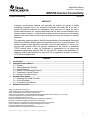
ABSTRACT
Computer communication systems and especially the Internet are playing a rapidly
increasingly important role in our everyday environment. But today this is not only a
domain of personal computers or workstations. More and more, it makes its way to
smaller network nodes, too. Imagine applications that are able to control hardware via a
standard Internet browser, to transmit and visualize the state of sensors or automatically
generate and send E-mails on the occurrence of special events (for example, for security
purposes).
This application report describes in detail the implementation of an embedded Web server
based on the MSP430 ultralow-power microcontroller series from Texas Instruments. The
solution consists of both hardware (schematic, parts list) and software (C source). An
ethernet LAN controller offers the physical connection to the Internet. A downsized
TCP/IP protocol stack is used. Its functionality is encapsulated by an easy-to-use
application programming interface (API). By using this API, creating new applications or
modifying existing ones becomes an easy task. As an application example, a dynamic
HTTP server is implemented.
Contents
1
2
3
4
Introduction ........................................................................................................................................3
Important Protocol Basics................................................................................................................3
2.1 Ethernet........................................................................................................................................4
2.2 Address Resolution Protocol .......................................................................................................5
2.3 Internet Protocol...........................................................................................................................5
2.4 Internet Control Message Protocol..............................................................................................6
2.5 Transmission Control Protocol ....................................................................................................6
2.6 Hypertext Transfer Protocol.........................................................................................................7
Hardware Description........................................................................................................................7
3.1 Interfacing to the LAN Controller .................................................................................................8
3.2 Circuit Description........................................................................................................................9
3.3 Connection to the Network ........................................................................................................10
Software Description.......................................................................................................................11
Amiga is a trademark of Amiga, Inc.
Apple and Macintosh are trademarks of Apple Computer, Inc.
Athlon is a trademark of Advanced Micro Devices, Inc.
Cassiopeia is a trademark of Casio Keisanki Kabushiki Kaisha DBA Casio Computer Co., Ltd., Japan
Crystal is a trademark of Crystal Semiconductor Corporation.
Cirrus is a trademark of Cirrus Logic, Inc.
Microsoft and Internet Explorer are a trademarks of Microsoft Corporation.
Netmon is a trademark of Systems Enhancement Corporation.
Netscape Navigator is a trademark of Netscape Communications Corporation.
Open Transport is a trademark of Information Management Company.
Pentium is a trademark of Intel Corporation.
Other trademarks are the property of their respective owners.
ZIP file: http://www.ti.com/lit/zip/slaa137
1
SLAA137A
4.1 Ethernet Module .......................................................................................................................... 4
4.2 TCP/IP Module ............................................................................................................................ 4
4.2.1 Buffer Memory................................................................................................................. 4
4.2.2 Global Variables .............................................................................................................. 4
4.2.3 Demultiplexing and Processing of Received Frames..................................................... 4
4.2.4 Opening a Connection .................................................................................................... 4
4.2.5 Data Transfer .................................................................................................................. 4
4.2.6 Closing a Connection ...................................................................................................... 4
4.2.7 Using of Timers ............................................................................................................... 4
4.2.8 Retransmission of Data................................................................................................... 4
4.2.9 Summary ......................................................................................................................... 4
4.3 API............................................................................................................................................... 4
4.3.1 Functions ......................................................................................................................... 4
4.3.2 Flags ................................................................................................................................ 4
4.4 HTTP Server Application Example ............................................................................................. 4
4.4.1 Software Description ....................................................................................................... 4
4.4.2 Dynamic Web Page Example ......................................................................................... 4
5
References ......................................................................................................................................... 4
Appendix A. Application Schematic ....................................................................................................... 4
Appendix B. Parts List.............................................................................................................................. 4
Figures
Figure 1. ISO/OSI vs Internet Reference Model ................................................................................... 3
Figure 2. Data Encapsulation................................................................................................................. 4
Figure 3. Hardware Block Diagram ....................................................................................................... 4
Figure 4. Prototype Board With Components Installed...................................................................... 4
Figure 5. Using the Ethernet Module .................................................................................................... 4
Figure 6. DoNetworkStuff() Flowchart .................................................................................................. 4
Figure 7. Buffer Concept ........................................................................................................................ 4
Figure 8. Demultiplexing of Received Frames ..................................................................................... 4
Figure 9. Using DoNetworkStuff().......................................................................................................... 4
Figure 10. Transmitting of Data ............................................................................................................ 4
Figure 11. SocketStatus Register ......................................................................................................... 4
Figure 12. Data Reception ..................................................................................................................... 4
Figure 13. Web Server Main Module .................................................................................................... 4
Figure 14. Internet Explorer Screen ..................................................................................................... 4
Tables
Table 1.
Table 2.
Table 3.
Table 4.
Table 5.
Table 6.
2
Functions of Internet Reference Model Layers ................................................................... 4
Important HTTP Methods ....................................................................................................... 4
Overview of the Software Modules ....................................................................................... 4
Functions of the Ethernet Module......................................................................................... 4
Compatible Communication Systems .................................................................................. 4
Stack Error Codes................................................................................................................... 4
MSP430 Internet Connectivity
SLAA137A
1
Introduction
While known for its use in PC networks, the ethernet also offers a robust, well-understood and
reasonably priced technology for networking applications beyond the desktop computer. The
goal of this design is to show how easy it is to implement a TCP/IP stack as well as an ethernet
interface for the MSP430. It provides both a source code for the programmer as well as
schematics for the design engineer.
It is advantageous if the reader of this application report has a general knowledge of TCP/IP
networks and their related communication protocols. Section 2 contains some very basic
information about the protocols used. For more detailed information, additional sources of
information are mentioned. Sections 3 and 4 present both the hardware and software parts of
the demonstration board featured in this application report.
Using the knowledge of this demonstration board, many applications are imaginable. Think of
home automation, utility meters, appliances, security systems, card readers and building
controls that can be easily controlled using either special front-end software or a comfortable
Internet browser from anywhere around the world. The big advantage of an HTTP server in an
embedded environment is that the web browser manages the whole user interface. The
visualizing of information can be done simply by sending ASCII strings (HTML source) to the
client and therefore minimal resources are required.
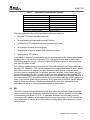
2 Important Protocol Basics
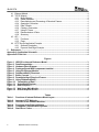
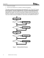
It is common to describe protocol stacks with a layered model. Each of these layers provides its
own functions to upper level protocols and also uses help of lower level protocols to provide its
services. The operational details of the lower layers are hidden from the higher layers. That
simplifies both software design and maintenance. For example, a new transport layer using a
different communication medium can be created, and it is not necessary to change the code of
the upper layers. The reference model commonly used for describing the Internet architecture is
a subset of the ISO/OSI seven-layer model. Figure 1 shows the relationship between these
models and Table 1 the function of the different layers in the Internet reference model.
Application Layer
Presentation Layer
Application Layer
Session Layer
Transport Layer
Transport Layer
Internet Layer
Network Layer
Network Layer
Data Link Layer
Physical Layer
Figure 1.
ISO/OSI vs Internet Reference Model
MSP430 Internet Connectivity
3
SLAA137A
Table 1.
Layer Name
Application layer
Transport layer
Internet layer
Network layer
Functions of Internet Reference Model Layers
Function
Contains a lot of protocols defined by different
applications to provide their services.
Makes the communication between endpoints
possible.
Delivery and routing of datagrams between
Internet nodes.
Host-specific implementation of transmission of
datagrams.
Example
HTTP, telnet, e-mail (SMTP, POP)
Transmission control protocol (TCP),
user datagram protocol (UDP)
Internet protocol (IP), Internet control
message protocol (ICMP), address
resolution protocol (ARP)
Ethernet (IEEE 802.3), point-to-point
protocol (PPP), AX.25
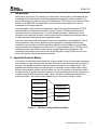
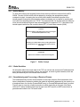
Beginning with the application where data is sent, each layer adds its own header to the
segment. This is called data encapsulation (Figure 2). By receiving a frame for example from
ethernet, the TCP/IP stack has to evaluate and remove step by step the headers of the different
layers to extract the payload. A recommended source for background information about the
TCP/IP software architecture is Reference [1].
Application Layer
Data
Transport Layer
Internet Layer
Header
Figure 2.
2.1
Data
Header
Header
Data
Header
Header
Data
Receive
Send
Network Layer
Header
Data Encapsulation
Ethernet
Today, ethernet is the most common medium to transfer data in a local area network (LAN). It
belongs to the network layer in the Internet reference model. The standard IEEE 802.3 defines
possible bit rates, the physical realization of bit coding, and the frame format used. Ethernet
shares the bus and each network node has the same rights to access the media by the carrier
sense multiple access with collision detection (CSMA/CD) method. If a collision is detected, the
sending nodes stop transmitting and use a special back-off algorithm for retransmission. The
data stream is Manchester coded and transferred using differential two-wire lines (twisted pair
cable, RJ45) or coaxial cables (RG58, BNC).
4
MSP430 Internet Connectivity
SLAA137A
Every network node has its own unique physical address. It is 48 bits long and called the media
access control (MAC) address. The maximum length possible for an Ethernet frame is 1518
bytes. This size covers the whole frame, excluding the preamble. The preamble consists of
alternating zeros and ones and is used for synchronization purposes. It is followed by the real
frame. The first 48 bits are the destination and the second 48 bits are the source MAC address.
After that, a 2-byte value indicating the type of the frame is sent. This type field is used to decide
in the receiving stack to which upper level protocol the frame will be handed over. Afterwards a
maximum of 1500 data bytes can be transferred followed by a 4-byte automatically generated
cyclic redundancy check (CRC) value. Using this CRC, the ethernet ensures data integrity, but it
does not ensure the delivery or in-order delivery of a packet. There are many resources on the
Internet about ethernet.
2.2
Address Resolution Protocol
The address resolution protocol (ARP) is usually used in ethernet networks. Its main purpose is
to determine a physical network address (e.g., Ethernet/MAC address) from a logical one (e.g.,
IP address) for sending packets of higher-level protocols. The network station that wants to
exchange data with another peer broadcasts a packet to the LAN that is received and processed
by all other peers. If a station finds out that the target’s protocol address matches the one of its
own TCP/IP stack, it sends back an answer frame to the sender. Now the sender knows the
MAC address of its partner and can continue sending with Unicast packets. This protocol is
described in detail in RFC 826 [5].
2.3
Internet Protocol
The Internet protocol (IP) is designed for use in packet-based networks such as the Internet. It
provides mechanisms for transmitting datagrams from a source to a destination (addressing),
and for fragmentation if necessary for transmission through small-packet networks. The
demonstration board uses today’s most common protocol, version four (IPv4).
The communication partners are identified by fixed-length addresses (IP addresses). But there
is no guarantee for a reliable end-to-end data transmission, flow control, sequencing and other
services commonly found in host-to-host protocols. If such features are needed, a higher-level
protocol must be used for data transfer (the most common in Internet is the TCP). There is no
assurance that the data sent along the datagram is error free, however the IP header is
protected by a checksum. Each IP packet has a protocol field indicating to which upper layer
protocol the carried data belongs.
Each Internet datagram is treated as a fully independent entity unrelated to any other datagram
and therefore IP is connectionless. A datagram can fail to reach its destination for different
reasons:
•
The destination host is not connected to the network
•
The datagram was damaged
•
A router misdirected the datagram
Upper level protocols (for example, TCP) can compensate for these types of failures. Refer to
RFC 791 [2] for a more detailed description.
MSP430 Internet Connectivity
5
SLAA137A
2.4
Internet Control Message Protocol
The internet control message protocol (ICMP) provides a mechanism for reporting problems and
generating diagnostic messages, e.g., when a datagram cannot reach its destination, when a
gateway does not have the buffering capacity to forward a datagram, or when the gateway
recommends a shorter route. Thus the datagram service can achieve a better communication
reliability. The ICMP uses the basic support of IP. However, it is an integral part of the IP layer.
Information about this protocol can be found in Reference [3].
The only two messages that are of interest for this application are the ECHO and the ECHO
REPLY messages. They are mainly used by the operating-system command-line utility PING. It
sends an ECHO message to another host which answers with an ECHO-REPLY message and
also sends back the received data. The PING tool draws information about the round-trip time
(RTT) and the reliability of a network.
2.5
Transmission Control Protocol
The transmission control protocol (TCP) is a transport-layer protocol from the TCP/IP network
stack. It is a highly reliable, connection-oriented host-to-host protocol for use in a packetswitched network. It is the most established transport layer for commonly used Internet protocols
(e.g. HTTP, SMTP, FTP, telnet). A simple, potentially unreliable datagram service of a lower
level protocol (such as IP) is enough for TCP to provide its service. To provide this service, the
following mechanisms are implemented:
•
Basic data transfer: TCP splits a continuous stream of bytes in segments and sends them
out as IP-frames.
•
Reliability: Recovery from damaged, lost or duplicated data is achieved by assigning a
sequence number to each byte and some of the special flags. The sending TCP also
requires an acknowledgement from the receiving TCP. If this is not received within a
timeout period, data is sent again.
•
Flow control: Each time a TCP receives a frame, it tells the other TCP how many bytes it is
allowed to send before further permission is needed.
•
Multiplexing: The TCP introduces port numbers that allow multiplexing of IP addresses. Any
combination of an IP address and a port-number is called a socket. A unique TCP
connection is determined by a pair of sockets.
•
Connections: Before data transfer can take place, a connection between the host and the
client must be established. This is done by using a three-way handshake. During this
handshake, the sequence numbers are synchronized. Afterwards the normal data transfer
can begin.
A TCP session runs through different states from establishing to closing. The state changes
occur as a reaction to different events. These events can be user function calls as well as
receiving segments or time-controlled actions. For detailed information about the TCP state
machine and how to work with it, see RFC 793 [4] and RFC 1122 [6].
6
MSP430 Internet Connectivity
SLAA137A
2.6
Hypertext Transfer Protocol
The hypertext transfer protocol (HTTP) is an application level protocol. It is a generic, stateless,
object oriented protocol that can be used for many tasks, such as name servers and distributed
object management systems, through extension of its request methods (commands). It uses a
client-server relationship and is based on a stream-oriented transport layer, such as TCP.
Today, the most important use is transferring HTML documents with multimedia contents
between Internet servers and clients (WWW). It works with the principle of request and
response. The simplest case is that a client establishes a connection to a server and requests a
content referred by a uniform resource identifier (URI) that specifies the path and name of the
resource. Commonly, this is done by navigating with the web browser. These URIs are
structured like a file path. After decoding the request, the server starts transferring the resource
to the client. The requests (also called methods) are sent as simple ASCII strings with a trailing
carriage return (CR) and line feed (LF) (Table 2).
Table 2.
Method
GET
Important HTTP Methods
HEAD
Description
A client requests a resource from a server. Afterwards, the server sends a header field and the
resource to the client.
Similar to get, but only the header-information about the resource is sent, not the resource itself.
POST
Used to transfer information from client to server (for example, pushing a button on a web page).
The response from a server contains some header lines. Each one has a CR and LF at its end.
An additional CR and LF at the end of the last line of the header indicate that the data is
following. In most cases, this will be an HTML page or a picture file. After transferring the
content, the connection is usually closed again. HTTP protocol version 1.0 is described in RFC
1945.
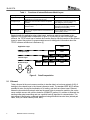
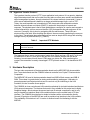
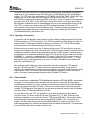
3 Hardware Description
The two main components of the demonstration board are the MSP430F149 microcontroller
from Texas Instruments and the CS8900A ethernet controller from Crystal™ Semiconductor
Corporation.
The MSP430F149 used in the demonstration board has 60KB of flash memory and 2KB of
RAM. This makes it a good choice for storing and transferring web pages. It has also six
general-purpose input/output ports that can be used not only for interfacing to the LAN
controller, but also to realize a user project.
The CS8900A is a low-cost ethernet LAN controller optimized for industrial-standard-architecture
(ISA) personal computers. The features that made it very suitable for this project are its highly
integrated design, which reduces the amount and cost of external components, and its very
easy-to-handle bus interface. Most LAN controllers that are on the market have a PCI bus
interface. The CS8900A bus interface is simple to interface with a microcontroller directly.
General I/O port pins of the MSP430 are used to provide a bus interface to the LAN controller.
The availability of this device in a 3-V version is another benefit for interfacing it with the
MSP430.
MSP430 Internet Connectivity
7
SLAA137A
8 MHz
20 MHz
D[7..0]
JTAG
MSP430F149
A[3..0]
CS8900A
IOR
IOW
Isolation
Transformer
LEDs: Power,
Link, LAN
RJ45
Connector
Figure 3.
3.1
Hardware Block Diagram
Interfacing to the LAN Controller
The most interesting thing is the connection between the LAN controller (IC2) and the MCU
(IC1). The CS8900A can operate in three different modes: I/O space, memory space, and as a
DMA slave. All of these modes have their special advantages and disadvantages. For this
project, the I/O space operation mode is the best choice. This is the default mode and is always
enabled. The most important fact is that it is possible to use an 8-bit width data bus (see
Resource [10] for a detailed description). This data bus is connected to general I/O-port 5 of the
MSP430. The CS8900A in I/O mode is accessed through eight 16-bit I/O ports that are mapped
into 16 registers. To access them, a 4-bit address bus width is used. There are also two control
lines used, IOR and IOW. These signals are active-low and indicate whether there is a read or a
write access in progress. The whole interface is implemented by using only 14 electrical signals.
All unused pins of the CS8900A are driven to appropriate levels to choose the operating mode
and configure the bus interface. For example, after any reset the CS8900A responds to default
I/O address 0x300. The address lines that are not changed while accessing this I/O address are
hardwired to 0x300.
After applying a valid I/O address to the address bus and driving one of the control lines (IOR,
IOW) to low, data transfer over the data bus can take place.
8
MSP430 Internet Connectivity
SLAA137A
3.2
Circuit Description
The analog circuitry around the CS8900A is built as further described in Resource [8]. A 20-MHz
crystal is connected between the pins XTAL1 (pin 97) and XTAL2 (pin 98) of the CS8900A.
Because of the built-in loading capacitance on the XTAL pins, no external capacitors are
needed. The power-on reset signal is generated by the R/C combination R9/C17. The LAN
controller, other than the MSP430, needs an active-high reset signal. The ethernet controller has
different outputs pins to control LEDs. Pin 100 (LANLED) goes low when the CS8900A transmits
or receives a frame and is connected to a red LED (D1). A yellow LED (D2) connected to pin 99
(LINKLED) is switched on if valid 10Base-T link pulses are detected. The same circuit as well as
the bus interface shown can be implemented directly on a user PCB that can also contain a
special analog application.
The circuitry connected to MSP430F149 contains the described connection to the LAN controller
as well as a JTAG interface, a crystal oscillator and a reset circuit. The JTAG interface is
designed for programming and debugging purposes. It can be used to directly connect the
MSP430 flash emulation tool (FET). All required signals (for example TCK, TDI, TDO/TDI, TMS)
are available at a 14-pin header (X6). An RS232 interface can be added if needed, for example
to establish an SLIP or PPP Internet connection after appropriate software changes. You can
use the TI device MAX3221. This part operates from a single 3.3-V supply voltage and only
needs four small 0.1 µF external capacitors. It has one serial line receiver and one serial line
transmitter and also low-power features which make it very suitable for this task. To get the
maximum MCU performance possible, it is sourced by an 8-MHz crystal. Two capacitors with 15
pF each are used to connect the oscillator pins to ground.
The circuit can be powered by connecting an adequate 3.3-V power supply to pin header X3.
The LED D4 (green) indicates the correct supplying of the module.
All MCU pins not used, as well as the supply potentials, are connected to pin headers X3 and
X4. They can be used for expansion purposes to build and attach a user application circuit.
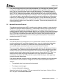
When designing a PCB for the circuit, be certain to provide a very clean and adequate power
supply to the MSP430 as well to the CS8900A by using bypass capacitors situated next to these
chips and short copper traces. Also especially take care about the design of the analog part
around the LAN controller (use Reference [9] as a detailed guide). For reasons of better routing
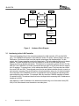
ability and EMI reasons, use of a four-layered board is recommended. Figure 4 shows the
prototype board used for developing the Web server software.
MSP430 Internet Connectivity
9
SLAA137A
Figure 4.
Prototype Board With Components Installed
Appendix A shows the schematic and Appendix B provides a list of components that are needed
to build the module. For each of the discrete parts, there are several manufacturers available.
3.3
Connection to the Network
The CS8900A includes an integrated 10Base-T transceiver. It contains all the analog and digital
circuitry needed for implementing the LAN interface by the use of a simple isolation transformer
(IND1). Similar devices can substitute for this part, but attention must be paid to the voltage turn
ratio between the primary and secondary windings. For 3.3-V operation, this must be 1:2.5 for
the transmission lines and 1:1 for the receive lines. The resistor R1 is used to terminate the
receive lines and the resistors R2 and R3 in series with the transmit lines are used for
impedance matching. The capacitors on the LAN side of the isolation transformer (C24, C25)
can be optionally populated if a shielded RJ45 connector is used. In this case, the signal GNDA
must be connected to the case shield. See Reference [9] for more background information.
A standard RJ45 patch cable can be used to connect the module to either a 10-Mbps or 100Mbps hub. A 100-Mbps hub automatically switches down its transfer speed to 10 Mbps if it
detects the CS8900A running at 10 Mbps.
10
MSP430 Internet Connectivity
SLAA137A
4 Software Description
This chapter describes the implemented TCP/IP stack, the ethernet driver, and the HTTP server.
The entire software is written in C and therefore porting to other MCU systems should be quite
easy. For reasons of better understanding, the code is separated into different modules. Table 3
gives an overview of these modules.
Table 3.
Application
Overview of the Software Modules
•
Transfers data via ethernet and TCP/IP
•
TCP/IP module
(tcpip.c,
tcpip.h)
•
Uses the API functions of the TCP/IP module which encapsulates the whole
stack and hides it from the application
Is a library for application development
•
Implements the protocols ARP, ICMP, IP and TCP
•
Reacts on events (frame reception, API calls by the user)
Ethernet module
(cs8900.c,
cs8900.h)
•
Hardware driver for using the CS8900A LAN controller
•
Provides functions for configuration purposes as well as for reading and writing of
registers and sending and receiving of ethernet frames
Ethernet
•
Physical layer on which the data transfer takes place; access is via the LAN
controller
NOTE: For developing a user application, it is highly recommended to use a network monitor
program for examining and decoding ethernet frames (for example, Microsoft™ Netmon™).
4.1
Ethernet Module
The main task of the ethernet module cs8900.c is the encapsulation of functions for data
transmission by easy-to-use C functions. The ethernet module also generates the clock scheme
used for accessing the internal registers of the CS8900A.
In the header file cs8900.h, several things concerning the network interface can be configured. A
very important setting is the MAC address of the network interface. This 48-bit address is
defined using six symbolic constants MYMAC_1 to MYMAC_6. The user can modify this
address, but must ensure that it is unique in the local network. An address of FFFF FFFF FFFF
is not allowed because this is reserved as a broadcast address and therefore cannot be used as
an individual one.
Table 4 gives an overview of the ethernet module procedures, and Figure 5 shows how to use
them.
MSP430 Internet Connectivity
11
SLAA137A
Table 4.
Functions of the Ethernet Module
Name, Parameters
void Init8900(void)
void Write8900(unsigned char
Address, unsigned int Data)
void WriteFrame8900(unsigned int
Data)
unsigned int Read8900(unsigned int
Address)
unsigned int ReadFrame8900(void)
unsigned int
ReadHB1ST8900(unsigned char
Address)
unsigned int ReadFrameBE8900(void)
void CopyToFrame8900(void *Source,
unsigned int Size)
void CopyFromFrame8900(void *Dest,
unsigned int Size)
void
DummyReadFrame8900(unsigned int
Size)
void RequestSend(unsigned int
FrameSize)
unsigned int Rdy4Tx(void)
Description
Initializes important MCU port pins, does a software reset of the LAN
controller, and sets up the LAN controller MAC interface.
Writes the 16-bit value Data to one of the eight possible registers of the
CS8900A (Address). Data is written in little-endian byte order to the LAN
controller memory.
Writes the 16-bit value Data to the I/O address TX_FRAME_PORT of
the CS8900A. Used to transfer a word into the transmit buffer
Reads a 16-bit value from a given I/O address of the LAN controller.
Byte order is little-endian.
Reads a 16-bit value from LAN controller’s RX_FRAME_PORT address.
Used to transfer data to MCU memory. Byte order is little-endian.
Reads a 16-bit value from a given address, but the byte on the upper
address is read out first. This function must be used to access special
registers of CS8900A. Byte order is little-endian.
Reads a 16-bit value from LAN controller’s RX_FRAME_PORT address.
Used to transfer data to MCU memory. Byte order is big-endian. Use
this function to avoid byte swapping when reading data of higher layered
communication protocols.
Copies Size bytes, starting with address Source from MCU memory to
the CS8900A TX_FRAME_PORT. Used to send out a whole prepared
frame.
Reads out Size bytes from the LAN controller frame port and transfers it
to MCU memory
Reads and discards Size bytes from the CS8900A RX_FRAME_PORT.
Used to skip a received frame. Size must be an even number.
Requests FrameSize bytes in the LAN controller transmit buffer. This
function must have been called before writing data to
TX_FRAME_PORT.
Checks whether previously requested buffer space in the LAN controller
is available (return value is not equal to zero), and therefore the frame
can be copied to the TX buffer.
At first, the ethernet controller must be configured. This is done by calling the function Init8900().
The ethernet controller is reset and the configuration sequence stored in the C-constant
InitSequ[ ] is transferred. Every entity in this constant consists of an address and a data value.
The meaning of the registers accessed and the symbols used is described in detail in the
CS8900A data sheet [8]. After this preparation, data transfer can take place.
12
MSP430 Internet Connectivity
SLAA137A
Init8900()
User Program
Write8900(ADD_PORT, PP_RxEvent)
(Read8900(DATA_PORT)
& RX_OK)?
Yes
CopyFromFrame8900(...)
No
Yes
Application Wants
to Send Data?
RequestSend(FrameSize)
No
Rdy4Tx()?
No
Yes
RequestSend(FrameSize)
Figure 5.
4.2
Using the Ethernet Module
TCP/IP Module
This software module represents the most important part of the demonstration board because
the protocols for transferring data over a TCP/IP connection are implemented here. It uses
functions of the ethernet module to send and receive data and provides a simple, easy-to-use
API to the upper application layer.
Basically the module tcpip.c is a collection of event-handling procedures and some help
functions (for example, reversing the byte order of words). In a TCP/IP stack one of the following
events can occur:
•
A frame is received over the LAN
•
The application triggers an event (for example opens a connection, sends data…)
MSP430 Internet Connectivity
13
SLAA137A
•
A time-out is exceeded
•
An error occurs (network error, connection is reset by the opponent)
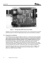
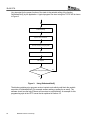
The software implements the essential parts of the standards RFC 791, 792 and 793. The most
important function of this stack is DoNetworkStuff(). This function must be called periodically by
the user application. The event handling of the TCP is done here. Different flags are polled in
both the ethernet controller and the MCU. According to the flags, this function branches to the
appropriate event handler. The more often this function is called, the better the performance of
the TCP is. A special set of event handlers is the user events. They are triggered by calling one
of the stack functions directly by the application. These functions are described in Section 4.3.
Read RxEvent Register of CS8900A
Yes
Frame Received?
Demultiplexing
(DA = Broadcast / Individual)
No
Yes
Timer Event Occured?
Handle Retransmission or Timeout Error,
Close Connection if Requested.
No
Adapt the TCP State Machine According to
Global Flags.
Yes
TxFrame2 Buffer Send Requested?
Request Memory in LAN Controller and Send
the TxFrame2 Buffer.
No
Yes
TxFrame1 Buffer Send Requested?
Request Memory in LAN Controller and Send
the TxFrame1 Buffer.
No
Figure 6.
14
MSP430 Internet Connectivity
DoNetworkStuff() Flowchart
SLAA137A
4.2.1 Buffer Memory
To work with incoming and outgoing frames, three memory buffers are reserved in the MCU
SRAM. The size of these buffers can be adapted by changing the appropriate symbolic
constants in tcpip.h. Increasing the size of the buffers leads to a dramatic increase of the
transfer speed, because the demonstration software maintains only one buffer for sending and
one buffer for transmitting data over TCP/IP. This transmit buffer can be filled with new data only
when the last transferred segment was acknowledged by the opponent TCP. A decrease in the
transfer speed results from the round-trip times (RTT) in a wide area network (WAN).
TxFrame1
Buffering of Whole TCP Data Frames to Send, Including All
Headers Needed (Ethernet, IP, TCP).
TxFrame2
Buffering of TCP Non-Data Frames, Including All Headers
Needed (Ethernet, IP, TCP) and Frames of the Protocols
ARP, ICMP.
RxTCPBuffer
Space for the User Data of a Received TCP Segment.
Figure 7.
Buffer Concept
4.2.2 Global Variables
All information about the current state of the TCP, as well as local and remote IP addresses and
port numbers, sequence numbers, timers, and counters, is stored in global variables, which are
easily accessible by all of the internal stack functions.
4.2.3 Demultiplexing and Processing of Received Frames
The DoNetworkStuff() function checks whether a frame was received. After examination of the
frame’s destination to determine whether the packet is individually addressed to the module or is
a broadcast frame, the function ProcessEthIAFrame() or ProcessEthBroadcastFrame() is called.
Figure 8 gives an overview of which procedure is called, depending on the type of the frame
received. If it was a broadcast frame and its type is an ARP request, an ARP answer frame is
generated and written to the TxFrame2 buffer.
MSP430 Internet Connectivity
15
SLAA137A
Frame Was Received.
Individually Addressed?
Broadcast?
ARP, Opcode REPLY?
IP?
Process Frame.
ICMP?
TCP?
ProcessICMPFrame()
ProcessTCPFrame()
Figure 8.
Demultiplexing of Received Frames
If the frame was individually addressed, it is first checked to determine if it is an ARP answer
frame for a previously sent ARP request of the local TCP. In this case, the opponent’s MAC
address is extracted. This mechanism is used for performing an active open of a connection. For
the case that the received frame type is IP and its destination address matches the one of the
local TCP, a jump to the function ProcessICMPFrame() or ProcessTCPFrame() is executed,
depending on the IP protocol number.
The procedure ProcessICMPFrame() checks to determine if the frame is an ICMP echo request
and generates an ICMP echo reply. Other types of ICMP messages are ignored and discarded.
If the frame type is TCP, steps for processing incoming TCP segments recommended in RFC
793 are executed. First, the frame is checked to determine if a TCP session is active and
whether the frame belongs to this session, or if a request from another TCP for establishing a
connection was received (segment carries a SYN flag). Afterwards, the state of the variable
TCPStateMachine is changed according to the flags of the segment that arrived. When data is
sent along the segment and the receive buffer is empty, this data is copied to the RxTCPBuffer
memory space. Valid arriving segments are acknowledged by sending a TCP ACK segment.
The program only accepts incoming segments that correspond to the sequence number of the
last segment that was acknowledged. Due to the relatively small amount of memory, no
buffering can be done for segments that are delivered out of order. Preparing a non-data TCP
segment is done by using the PrepareTCPFrame() function. A valid combination of TCP flags is
passed as an argument. The whole frame (including its headers) is generated in the TxFrame2
buffer. For example, calling PrepareTCPFrame(TCP_CODE_ACK) creates an
acknowledgement segment.
16
MSP430 Internet Connectivity
SLAA137A
To prevent the receive buffer from corruption while receiving data, a handshake mechanism is
implemented. This mechanism uses the SOCK_DATA_AVAILABLE flag of the SocketStatus
register. The TCP stack only copies data to RxTCPBuffer if the SOCK_DATA_ AVAILABLE flag
is clear, and only in this case is an ACK-segment sent back to the other TCP. If the
RxTCPBuffer is empty and the stack has written new data to it, this is indicated to the application
by setting the SOCK_DATA_AVAILABLE flag. If the receive buffer is not empty, the incoming
data segment is discarded and not acknowledged. But due to the retransmission timeout of the
other TCP, no data is lost, because the other TCP retransmits its data until the local TCP
receive buffer is empty and can acknowledge the data. To avoid permanent retransmissions, the
local application should release the receive buffer frequently by calling the API-function
TCPReleaseRxBuffer() (see Section 4.3).
4.2.4 Opening a Connection
A connection can be opened in either passive or active mode by calling the proper API function
TCPPassiveOpen() or TCPActiveOpen(). The TCPPassiveOpen() function places the stack in a
mode in which it is attempting to detect an incoming connection. The TCPLocalPort variable
must have been set to indicate which port the stack must monitor.
Before performing an active open, the IP address of the remote TCP as well as the local and
remote port numbers must be set. After calling the TCPActiveOpen() function, the stack first tries
to determine the MAC address of the opponent by sending an ARP request. The stack checks
the destination IP to determine whether the other TCP is a member of the subnet (see symbols
SUBMASK_1…4), and if so, addresses that TCP directly. If the other TCP is not a member of
the subnet, the ARP request is performed for the default gateway (symbols GWIP_1…4) and
data transfer occurs over the gateway as a router. For further information about subnets and
gateways, see Reference [1].
After finding the MAC address to communicate with, the stack sends out a TCP segment
carrying a SYN flag and the TCP option maximum segment size (MSS). Along with this
segment, the initial sequence number required for opening a connection and also the size of the
receive buffer is sent. This ensures that no arriving segment exceeds the size of the receive
buffer. This frame is also prepared using the function PrepareTCPFrame().
4.2.5 Data Transfer
Once a connection is established (TCPStateMachine changes to ESTABLISHED), data transfer
can begin. The actual state of the connection can be read out by using the API flag register
SocketStatus (see Section 4.3). The receiving and transferring of data into the receive buffer is
done by the function ProcessTCPFrame(). The count of received bytes is stored in the global
variable TCPRxDataCount. New data can only be received when the receive buffer is released.
Use the function TCPReleaseRxBuffer() to do this.
To send data to the other TCP, the application has to write its data into the data area of
TxFrame1 buffer. For direct access to this area, the pointer TCP_TX_BUF should be used.
Sending is initiated by a user call of the function TCPTransmitTxBuffer(). This function checks
whether sending is allowed and then sets the flag SEND_FRAME1 in the TransmitControl
register. This flag leads during execution of DoNetWorkStuff() to sending of the frame. If an
acknowledge segment is received, the transmit buffer is released automatically. The application
then can fill the buffer with new data and send it out.
MSP430 Internet Connectivity
17
SLAA137A
4.2.6 Closing a Connection
A TCP connection can be closed on different events. Normally this is done either locally by
calling the user function TCPClose() or remotely by the other TCP. During the termination of a
connection, segments carrying FIN flags are exchanged. If the retransmission counter exceeds
a limit or a segment with a RST (reset) flag is received, the connection is also closed. This is an
error situation that is indicated by an error code in the SocketStatus register.
4.2.7 Using of Timers
When implementing a TCP, different tasks must be performed with controlled timing. The stack
uses Timer_A of the MSP430, which is configured by the function TCPLowLevelInit(). The
protocol specification for TCP (RFC 793) demands a 32-bit wide, free-running counter with a
frequency of 250 kHz. It is used for getting the initial sequence number (ISN) needed for
opening a connection. An 8-MHz crystal drives the MSP430. This clock is divided by 32, down to
250 kHz, and sources a 16-bit wide, free-running counter (TAR). An interrupt is generated each
time the TAR register completes an interval (every 0.262s using an 8-MHz MCU clock). In this
case, the interrupt service routine TCPClockHandler() increments the 16-bit number
ISNGenHigh. This variable represents the upper word of the ISN. On each timer interrupt event,
the variable TCPTimer is also incremented. It is used to generate the timer events needed for a
TCP. For example, if the other TCP does not acknowledge a segment sent within a specific time
interval, a retransmission is triggered. Also, on closing a connection, the TCP has to wait before
another TCP connection can be opened.
4.2.8 Retransmission of Data
In order to avoid a breakdown of the TCP connection caused by loss of transmitted data, a timecontrolled mechanism for retransmitting of data is implemented. The TCP stack writes the type
of every frame sent to the LastFrameSent register. When the time counter exceeds the
RETRY_TIMEOUT (symbolic constant, tcpip.h) limit, the frame is resent using the function
TCPHandleRetransmission(). The maximum count of retransmissions per segment is defined in
the constant MAX_RETRYS. If this count is exceeded, the current TCP session is closed and an
error is indicated. This mechanism is not used for sent segments that only contain an ACK flag
because they are not acknowledged and therefore need no retransmission.
4.2.9 Summary
In spite of the fact that during software development many compromises were made [6], the
compatibility of the stack in communicating with other TCPs is very good. No other TCP had
problems establishing a connection during the software evaluation. Table 5 gives a list of several
computers and operating systems where data exchange over TCP/IP is possible.
18
MSP430 Internet Connectivity
SLAA137A
Table 5.
Compatible Communication Systems
Computer System / CPU
PC / Athlon™/ 1 GHz
Operating System, TCP/IP Stack
Windows 2000
PC / Athlon / 1 GHz
PC / Pentium™ / 233 MHz
Linux, kernel v 2.2.16
Windows 98
PC / 486DX2 / 66 MHz
Apple™ Macintosh™ / 68030 / 50 MHz
Windows 95
System 7.5, Open Transport™ 1.1.2
AT Amiga™ / 68030 / 50 MHz
Cassiopeia™ / MIPS / 150 MHz
Kickstart 3.0, Miami 2.1
Windows CE 3.0
The main limitations of the protocol specifications that were made are:
•
Only one TCP session possible at one time
•
No reassembling of fragmented incoming IP frames
•
No buffering of TCP segments which are delivered out-of-order
•
No checksum checking of incoming data
•
No support for IP type-of-service (TOS) and security options
•
Ignoring of any TCP options
Compatibility is achieved by implementing only the important parts of the protocol specifications,
but also is due to the tolerance of the other TCPs. This solution needs about 4.2KB of flash
EEPROM as program memory, 100 bytes of flash EEPROM as memory for storing constants,
and about 700 bytes of RAM.
The maximum transfer speed of the module cannot be defined exactly, as it largely depends on
the other TCP. Normally, a TCP that fully implements the protocol specification is able to receive
and buffer more than one segment at a time. Because the MSP430 has a relatively small
amount of memory compared with, for example, personal computers, it can maintain only one
receive and one transmit buffer. It needs to wait for an acknowledgement from the other TCP
before the overwriting of buffer contents is allowed and new data can be exchanged. Because of
the round-trip time (RTT) of packets sent over the Internet and the delaying of ACK segments by
some TCPs, transfer speed varies significantly. During evaluation of the stack, transfer speeds
between 2 and some dozens of KBps were measured. But most of the applications for an
embedded web server do not require transfer speeds of several Mbps.
4.3
API
The wish to enable existing applications as well as to create new embedded applications with
Internet connectivity was an important reason for this project. Without spending excessive time
in understanding the details of TCP/IP, an application developer should be able to use the
functionality of this stack by calling simple functions to query some flags. The API consists of a
set of subroutines for sending and receiving data and a flag register that indicates the current
status of stack.
MSP430 Internet Connectivity
19
SLAA137A
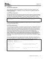
Very important for the proper function of the stack is the periodic calling of the function
DoNetworkStuff() by the application. A typical program flow chart using this TCP/IP API is shown
in Figure 9.
DoNetworkStuff()
Open or Close Connection
Process Incoming or Outgoing Data
Misc Program
Misc Program
No
Termination of Program Requested?
Yes
Figure 9.
Using DoNetworkStuff()
The blocks containing misc program must not contain code which could block the periodic
execution of DoNetworkStuff() (for example endless waiting or polling for an event). The
software should use the help of timers and counters to avoid blocking. An example for this
programming style is the HTTP server that is explained in Section 4.4.
20
MSP430 Internet Connectivity
SLAA137A
4.3.1 Functions
void TCPLowLevelInit(void)
This function does a basic setup of the ethernet controller and numerous variables; it also
configures ports and timer_A of MSP430. It must be called before any data transmission via
TCP/IP can take place.
void TCPPassiveOpen(void)
By calling this function, the stack switches to the server mode to detect an incoming connection.
The flag SOCK_ACTIVE is set indicating the stack is busy now. Before calling this function, the
local TCP port must have been configured. The local IP address is specified by a constant
declaration in the header file tcpip.h. The following example shows how to open a connection.
TCPLocalPort = 80;
TCPPassiveOpen();
// port of a HTTP-server
// listen for any incoming connection
(…)
If a client successfully establishes a connection to the server, the SOCK_CONNECTED flag in
the register SocketStatus is set.
void TCPActiveOpen(void)
This procedure tries to establish a connection to a remote TCP server. The flag SOCK_ACTIVE
is set and an ARP request to find out the MAC address of the other TCP will be sent out. If the
destination IP address does not belong to the actual subnet, the IP address of the gateway is
used for the ARP request instead. The IP addresses as well as the local and remote TCP port
must be set up before doing an active open. After the opening of the connection, the
synchronization of the TCPs, and the state change of the local TCP to ESTABLISHED, the
SOCK_CONNECTED flag is set and data transfer can take place by using the appropriate API
functions. If an error occurs while opening the connection (for example, destination host is
unreachable), the connection is reset and an error code is stored into the SocketStatus variable
accordingly.
The following example shows how to perform an active open. If the module is connected to a
router and the gateway IP is configured properly, you should be able to read out the quote of the
day of a real Internet server from MCU memory by using the flash emulation tool (FET).
*(unsigned char *)RemoteIP = 24;
// destination IP: 24.8.69.7
*((unsigned char *)RemoteIP + 1) = 8;
*((unsigned char *)RemoteIP + 2) = 69;
*((unsigned char *)RemoteIP + 3) = 7;
TCPLocalPort = 2025;
TCPRemotePort = 17;
// local TCP port doesn’t matter (>1024)
// standard port: “quote of the day”
TCPActiveOpen();
while (SocketStatus & SOCK_ACTIVE)
{
DoNetworkStuff();
}
// wait for closing the connection by the
// other TCP
MSP430 Internet Connectivity
21
SLAA137A
void TCPClose(void)
Use this API function to close an open connection. Before disconnecting, the stack ensures that
a packet that still resides in the output buffer is transmitted and acknowledged properly. After
closing, the application may reconfigure IP addresses, reassign port numbers, and open a new
connection.
void TCPReleaseRxBuffer(void)
After reading out the receive buffer, calling this function tells the stack that the buffer contents is
not needed anymore and may be overwritten by new incoming TCP data. This function also
clears the SOCK_TX_BUF_RELEASED flag used to indicate the presence of new data.
void TCPTransmitTxBuffer(void)
By using this function, an application can send data over an already opened connection. First,
the application has to check if it may write data to the transmit buffer. This is done by testing the
flag SOCK_TX_BUF_RELEASED of the SocketStatus register. If this flag is set, the application
may write a maximum of MAX_TCP_TX_DATA_SIZE bytes to the transmit buffer, starting at
address TCP_TX_BUF (points to the data section of the TxFrame1 buffer). Afterwards, the byte
count must be written to TCPTxDataCount register. Finally, calling TCPTransmitTxBuffer() leads
to the transmission of the data (Figure 10).
Yes
TX_BUF_RELEASED?
Copy Data to Transmit to TCP_TX_BUF
No
TCPTxDataCount = Number of Bytes to Send
TCPTransmitTxBuffer()
Figure 10. Transmitting of Data
4.3.2 Flags
The API status flags are stored in the global 8-bit variable SocketStatus. This register can only
be read out. The bit positions of the described flags are shown in Figure 11.
22
MSP430 Internet Connectivity
SLAA137A
Bit 7
SOCK_
ERROR
Bit 6
SOCK_
ERROR
Bit 5
SOCK_
ERROR
Bit 4
SOCK_
ERROR
Bit 3
SOCK_TX_BUF_
RELEASED
Bit 2
SOCK_DATA_
AVAILABLE
Bit 1
SOCK_
CONNECTED
Bit 0
SOCK_
ACTIVE
Figure 11. SocketStatus Register
SOCK_ACTIVE (Bit 0)
This flag is set when the TCP is busy opening a connection (previous call of an API method to
open a session). While set, no further call of one of these functions is allowed. If an open fails or
the connection is closed normally, the stack clears this flag again. The occurrence of a possible
error is shown in the error code flags.
SOCK_CONNECTED (Bit 1)
This flag indicates that the state of the TCP state machine is established. If set, data transfer
using the appropriate API function can take place. On closing or resetting a connection this flag
is cleared.
SOCK_DATA_AVAILABLE (Bit 2)
This flag informs the application that a new TCP segment has just arrived and can be read out of
the receive buffer. To get simple access to this buffer, the pointer TCP_RX_BUF should be
used. The variable TCPRxDataCount contains the amount of data received. After reading the
contents of the buffer, the application should release the buffer by calling the API function
TCPReleaseRxBuffer() immediately so that the stack can fill in new data (see Figure 12). If the
buffer is not released for a longer time and therefore a lot of TCP segments have to be
discarded, the connection can be reset by the other TCP.
Yes
DATA_AVAILABLE?
No. of Bytes Rec'd = TCPRxDataCount
No
Read Out and Process rx Buffer Starting With
Address TCP_RX_BUF
TCPReleaseRxBuffer()
Figure 12. Data Reception
MSP430 Internet Connectivity
23
SLAA137A
SOCK_TX_BUF_RELEASED (Bit 3)
This flag indicates whether the application can change the contents of the transmit buffer or
modify the TCPTxDataCount variable. This flag is set by the stack if the previous packet sent
was acknowledged properly. This realizes a kind of handshake mechanism to protect the
transmit buffer from overwriting its contents. For the common way of sending data, see
description of the function TCPTransmitTxBuffer().
SOCK_ERROR (Bits 4 to 7)
If an error occurs while initiating a connection or transferring data, the stack writes an error code
to the upper nibble of register SocketStatus. By reading and interpreting this value, the
application can find out the reason for this error. It is recommended to get the error code by
isolating the upper nibble (AND-operation with SOCK_ERROR_MASK). The occurring of an
error but SOCK_ERR_OK immediately closes the connection. Table 6 gives an overview about
the error codes.
Table 6.
Error code
SOCK_ERR_OK
SOCK_ERR_ARP_TIMEOUT
SOCK_ERR_TCP_TIMEOUT
SOCK_ERR_CONN_RESET
SOCK_ERR_REMOTE
SOCK_ERR_ETHERNET
4.4
Stack Error Codes
Reason
No error.
Error during an ARP request occurred. The MAC address of the other TCP could
not be found. The other host is not connected to network or is not able to answer.
Timeout error during a TCP session occurred. Although the TCP segment was
sent several times, it was not acknowledged by the other TCP. May happen on a
very unreliable or interrupted connection.
A request to open a connection or an already existing connection was reset by
the other TCP. Either the other TCP cannot communicate at the given port or the
application layer of the other TCP has reset the connection (for example pushing
the STOP-button in an Internet browser).
A fatal error of the remote TCP led to the sending of an invalid segment.
The TCP/IP stack was not able to transmit data via ethernet (the LAN controller
provided no free buffer space for sending frames). This error occurs on cutting
the network cable (no LINK pulses are detected by the network controller).
HTTP Server Application Example
As an example of how to use the previously described TCP/IP stack, a demonstration HTTP
server was implemented. This server provides an HTML web page that is stored in MCU flash
memory. The module waits for an incoming connection, transfers the web page, closes the
connection and waits for another client to connect. The content of this web page is adapted
dynamically to physical values. In detail, two bar graph displays are implemented for showing
A/D converter values.
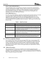
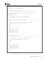
4.4.1 Software Description
This demonstration HTTP server is an example for the non-blocking programming style
demanded in the API paragraph (Section 4.3), to keep on calling the DoNetworkStuff() function
periodically. The source file name is easyweb.c and its most important function is HTTPServer().
Figure 13 shows the flowchart of this module.
24
MSP430 Internet Connectivity
SLAA137A
Initalizing of Clock System
Configure MCU's I/O Ports
TCPLowLevelInit()
Initialize HTTP Server's Flag-Register
TCPLocalPort = TCP_PORT_HTTP
No
SOCK_ACTIVE?
TCPPassiveOpen()
Yes
DoNetworkStuff()
HTTPServer()
Figure 13. Web Server Main Module
MSP430 Internet Connectivity
25
SLAA137A
After initializing some hardware and the stack itself, the local TCP port is set to 80 (default for an
HTTP server). The server is now waiting for a client to be connected. During the first jump to
HTTPServer() after connecting, the flag HTTP_SEND_PAGE in register HTTPStatus is clear. It
is used to process some special code sections during this first execution of HTTPServer(). The
web server checks for any incoming TCP data and discards it. It is assumed that the received
data contains a GET request from an Internet browser. Since our server supports only one web
page, this request is not evaluated. The server starts just after client connection by sending the
web page stored in MCU memory. This page is stored in the C-constant WebSide[ ] in module
webside.c and is not encoded in any special way. After checking the status of the transmit
buffer, a pointer to the web side is set up and the total number of bytes to send is stored in
HTTPBytesToSend. During the first call of HTTPServer(), an HTTP response header is
transferred directly before the web page. It tells the client that its request was decoded
successfully and lets it know what kind of resource will be transmitted (HTML). It is stored in the
constant GetResponse[ ] in easyweb.h. After that, the web page is sent in pieces of
MAX_TCP_TX_DATA_SIZE size. Following the successful transmission of the whole page the
connection is closed by calling the API function TCPClose(). The connection is then reopened
by the main() function so that the next client can request and get the web page.
How can a dynamic web page be achieved? Before sending a segment of TCP data, the
function InsertDynamicValues() is executed. This function searches the transmit buffer for
special strings. If such a string is found, it is replaced by an A/D converter value. These strings
consists of four bytes: AD + channel number + %. The demonstration HTTP server replaces the
string AD7% by the value of the A/D converter’s channel seven and ADA% by the value of
channel ten. Before inserting these values, they are scaled to a range from 0 through 100
percent. With knowledge about HTML programming, this can be used to achieve effects on the
Web page.
The value for replacing the AD7% string is generated by the function GetAD7Val(). The ADC12
module of the MSP430 is configured to use an internal reference voltage of 2.5 V. Channel
seven is associated with MSP430F149 port pin P6.7. The voltage of the pin is sampled and the
voltage range of 0 to 2.5 V is projected into a percentage from 0 to 100. The other A/D converter
function used is GetTempVal(). Channel ten is connected internally to a temperature reference
diode. By setting the reference voltage to 1.5 V and doing a multiple conversion of eight sample
points, the temperature of the MCU is measured. Using a special formula, the temperature
range from 20 °C to 45 °C is converted to a percentage from 0 to 100. This formula should not
be used for exact measuring; it is for demonstration purposes only.
4.4.2 Dynamic Web Page Example
The server module provides a simple web page. It uses the process of replacing special strings
to be dynamic. Along with general text, two bar-graph displays showing the values of ADC12
channels 7 and 10 are displayed. For realizing such bar graph displays, HTML table commands
can be used easily. Two tables having a defined width and the background color red are
programmed. Within these tables, there are two more tables with the background color green.
The width of the two inner tables can be referred to the width of the outer tables using a
percentage. This is a good place to invoke the replacement process.
26
MSP430 Internet Connectivity
SLAA137A
<html>
<head>
<meta http-equiv=“refresh” content=“5”>
<title>easyWEB - dynamic Webside</title>
</head>
<body bgcolor=“#3030A0” text=“#FFFF00”>
<p><b><font color=“#FFFFFF” size=“6”><i>Hello World!</i></font></b></p>
<p><b>This is a dynamic webside hosted by the embedded Webserver</b>
<b>easyWEB.</b></p>
<p><b>Hardware:</b></p>
<ul>
<li><b>MSP430F149, 8 MHz, 60KB Flash, 2KB SRAM</b></li>
<li><b>CS8900A Crystal Ethernet Controller</b></li>
</ul>
<p><b>A/D Converter Value Port P6.7:</b></p>
<table bgcolor=“#ff0000” border=“5” cellpadding=“0” cellspacing=“0” width=“500”>
<tr>
<td>
<table width=“AD7%” border=“0” cellpadding=“0” cellspacing=“0”>
<tr><td bgcolor=“#00ff00”> </td></tr>
</table>
</td>
</tr>
</table>
<table border=“0” width=“500”>
<tr>
<td width=“20%”>0V</td>
<td width=“20%”>0,5V</td>
<td width=“20%”>1V</td>
<td width=“20%”>1,5V</td>
<td width=“20%”>2V</td>
</tr>
</table>
<p><b>MCU Temperature:</b></p>
<table bgcolor=“#ff0000” border=“5” cellpadding=“0” cellspacing=“0” width=“500”>
<tr>
<td>
<table width=“ADA%” border=“0” cellpadding=“0” cellspacing=“0”>
<tr><td bgcolor=“#00ff00”> </td></tr>
</table>
</td>
</tr>
</table>
<table border=“0” width=“500”>
<tr>
<td width=“20%”>20°C</td>
<td width=“20%”>25°C</td>
<td width=“20%”>30°C</td>
<td width=“20%”>35°C</td>
<td width=“20%”>40°C</td>
</tr>
</table>
</body>
</html>
MSP430 Internet Connectivity
27
SLAA137A
By using the REFRESH statement in the HEAD section of the page’s source code, an Internet
browser can be advised to reload the page after a specified timeout period. In the demonstration
HTTP server, the page is reloaded each five seconds. The HTML code shown is compatible with
all common Internet browsers (such as Microsoft Internet Explorer™, Netscape Navigator™).
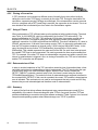
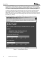
To display the web page using an Internet browser, the user has to enter the transfer protocol
(http://) together with the IP address of the module (set by default to 192.168.0.30) into the
address field. See Figure 14 for a snapshot. Of course, the module must have been powered on,
properly connected to LAN and the TCP/IP settings of the local machine must match to those of
the module (e.g., Subnet).
Much helpful information for creating efficient HTML code can be found on the Internet.
Figure 14. Internet Explorer Screen
28
MSP430 Internet Connectivity
SLAA137A
5 References
1. TCP/IP Running a Successful Network by Washburn, K., Evans, J. Addison Wesley, 1996
2. Internet Protocol (IP) by Postel, J., RFC 791†
3. Internet Control Message Protocol by Postel, J., RFC 792†
4. Transmission Control Protocol by Postel, J., RFC 793†
5. An Ethernet Address Resolution Protocol by Plummer, D., RFC 826†
6. Requirements for Internet Hosts by Braden, R., RFC 1122†
7. MSP430x13x, MSP430x14x Mixed Signal Microcontroller Data Sheet (SLAS272)
8. CS8900A Product Data Sheet. Cirrus™ Logic, Inc., 1999‡
9. CS8900A Ethernet Controller Technical Reference Manual (AN083). Cirrus Logic Inc., 2001‡
10. Using the Crystal CS8900A in 8-Bit Mode (AN181). Cirrus Logic, Inc., 2000‡
† Request for Comments is a collection of papers of Internet-related topics. Available for download at http://www.faqs.org/rfcs/index.html
‡ Available for download from the Cirrus Logic home page at http://www.crystal.com
MSP430 Internet Connectivity
29
SLAA137A
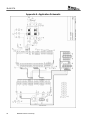
Appendix A. Application Schematic
30
MSP430 Internet Connectivity
SLAA137A
Appendix B. Parts List
Part Name
Value / Description
560 pF
Package
SMT 0805
C2, C3, C6, C13, C14, C15, C16,
C17, C18, C19, C20, C21, C22
C4, C5
0.1 µF (100n)
SMT 0805
15 pF
SMT 0805
C24, C25
D1
4700 pF / 2 kV (4n7)
LED red, 3 mm, 2 mA (rt)
D2
D4
LED yellow, 3 mm, 2 mA (ge)
LED green, 3 mm, 2 mA (gn)
IC1
IC2
MSP430F149
ISA ethernet controller
CS8900A-IQ3
(Crystal Semiconductor)
Transformer E2023
(Pulse Engineering)
20 MHz
QFP-64
TQFP-100
Q2
R1
8 MHz
100 Ω
HC-49
SMT 0805
R2, R3
8.2 Ω
SMT 0805
R4
4.7 kΩ (4K7)
SMT 0805
R5
4.99 kΩ, 1% (4K99)
SMT 0805
R6, R7, R10
560 Ω
SMT 0805
R8, R9
100 kΩ
SMT 0805
X2
X3, X4
RJ45 LAN connector
Header, 26-pin
ML26
X6
Header, 14-pin
ML14
C1
IND1
Q1
SO-16L
HC-49
MSP430 Internet Connectivity
31
IMPORTANT NOTICE
Texas Instruments Incorporated and its subsidiaries (TI) reserve the right to make corrections, enhancements, improvements and other
changes to its semiconductor products and services per JESD46, latest issue, and to discontinue any product or service per JESD48, latest
issue. Buyers should obtain the latest relevant information before placing orders and should verify that such information is current and
complete. All semiconductor products (also referred to herein as “components”) are sold subject to TI’s terms and conditions of sale
supplied at the time of order acknowledgment.
TI warrants performance of its components to the specifications applicable at the time of sale, in accordance with the warranty in TI’s terms
and conditions of sale of semiconductor products. Testing and other quality control techniques are used to the extent TI deems necessary
to support this warranty. Except where mandated by applicable law, testing of all parameters of each component is not necessarily
performed.
TI assumes no liability for applications assistance or the design of Buyers’ products. Buyers are responsible for their products and
applications using TI components. To minimize the risks associated with Buyers’ products and applications, Buyers should provide
adequate design and operating safeguards.
TI does not warrant or represent that any license, either express or implied, is granted under any patent right, copyright, mask work right, or
other intellectual property right relating to any combination, machine, or process in which TI components or services are used. Information
published by TI regarding third-party products or services does not constitute a license to use such products or services or a warranty or
endorsement thereof. Use of such information may require a license from a third party under the patents or other intellectual property of the
third party, or a license from TI under the patents or other intellectual property of TI.
Reproduction of significant portions of TI information in TI data books or data sheets is permissible only if reproduction is without alteration
and is accompanied by all associated warranties, conditions, limitations, and notices. TI is not responsible or liable for such altered
documentation. Information of third parties may be subject to additional restrictions.
Resale of TI components or services with statements different from or beyond the parameters stated by TI for that component or service
voids all express and any implied warranties for the associated TI component or service and is an unfair and deceptive business practice.
TI is not responsible or liable for any such statements.
Buyer acknowledges and agrees that it is solely responsible for compliance with all legal, regulatory and safety-related requirements
concerning its products, and any use of TI components in its applications, notwithstanding any applications-related information or support
that may be provided by TI. Buyer represents and agrees that it has all the necessary expertise to create and implement safeguards which
anticipate dangerous consequences of failures, monitor failures and their consequences, lessen the likelihood of failures that might cause
harm and take appropriate remedial actions. Buyer will fully indemnify TI and its representatives against any damages arising out of the use
of any TI components in safety-critical applications.
In some cases, TI components may be promoted specifically to facilitate safety-related applications. With such components, TI’s goal is to
help enable customers to design and create their own end-product solutions that meet applicable functional safety standards and
requirements. Nonetheless, such components are subject to these terms.
No TI components are authorized for use in FDA Class III (or similar life-critical medical equipment) unless authorized officers of the parties
have executed a special agreement specifically governing such use.
Only those TI components which TI has specifically designated as military grade or “enhanced plastic” are designed and intended for use in
military/aerospace applications or environments. Buyer acknowledges and agrees that any military or aerospace use of TI components
which have not been so designated is solely at the Buyer's risk, and that Buyer is solely responsible for compliance with all legal and
regulatory requirements in connection with such use.
TI has specifically designated certain components as meeting ISO/TS16949 requirements, mainly for automotive use. In any case of use of
non-designated products, TI will not be responsible for any failure to meet ISO/TS16949.
Products
Applications
Audio
www.ti.com/audio
Automotive and Transportation
www.ti.com/automotive
Amplifiers
amplifier.ti.com
Communications and Telecom
www.ti.com/communications
Data Converters
dataconverter.ti.com
Computers and Peripherals
www.ti.com/computers
DLP® Products
www.dlp.com
Consumer Electronics
www.ti.com/consumer-apps
DSP
dsp.ti.com
Energy and Lighting
www.ti.com/energy
Clocks and Timers
www.ti.com/clocks
Industrial
www.ti.com/industrial
Interface
interface.ti.com
Medical
www.ti.com/medical
Logic
logic.ti.com
Security
www.ti.com/security
Power Mgmt
power.ti.com
Space, Avionics and Defense
www.ti.com/space-avionics-defense
Microcontrollers
microcontroller.ti.com
Video and Imaging
www.ti.com/video
RFID
www.ti-rfid.com
OMAP Applications Processors
www.ti.com/omap
TI E2E Community
e2e.ti.com
Wireless Connectivity
www.ti.com/wirelessconnectivity
Mailing Address: Texas Instruments, Post Office Box 655303, Dallas, Texas 75265
Copyright © 2013, Texas Instruments Incorporated