1
Operators Manual
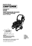
2.5 GPM
HIGH PRESSURE WASHER
CLEANING SYSTEM
Model No. 580.768030
HOURS: Mon. - Fri. 8 a.m. to 5 p.m. (CT)
CAUTION:
Before using this product, read this
manual and follow all its Safety Rules
and Operating Instructions.
Sears, Roebuck
and Co., Hoffman
Estates, IL 60179
Visit our Craftsman website: www.sears.GomJcmftsmen
Part No. B3595 D_tt $ (4/5/1999) Pr;.rttsd
in _
U.S.A.
•
•
•
•
•
Safety
Assembly
Operation
Maintenance
Parts
Warranty .........................
Safety Instructions ................
Assembly .........................
Operation .......................
Maintenance
..................
Storage
2
2-3
4
5-9
10-13
.........................
LIMITED
Troubleshooting ...................
Replacement Parts ..............
Emission Control
Warranty Statement .............
How to order parts and
request service .............
14
ONE YEAR WARRANTY
ON CRAFTSMAN
HIGH PRESSURE
15
17-25
26-27
Back page
WASHER
For one year from the date of purchese, when t_is Craftsman Cleaning System is maintained and operated
according to the instructions in the owner's manual, Sears will repair, free of charge, any defect in material and
workmanship.
If this washer is used for commemlal purposes, this warranty applies for only 90 days from the date of
purchase. If this high pressure washer is used for rental purposes, this warranty applies for only 30 days after
date of purchase.
This warranty does not cover:.
• Expendable items such as spark plugs, air filters, or chemical solutions.
• Repairs necessary because of operator abuse or negligence, including damage resulting from no water
being supplied to pump or failure to maintain the equipment according to the instructionscontained in the
owner's manual.
WARRANTY SERVICE IS AVAILABLE BY RETURNING THE HIGH PRESSURE WASHER TO THE
NEAREST SEARS SERVICE CENTER OR DEALER IN THE UNITED STATES.
This warranty gives you specific legal dghts and you may also have other rights, which vary from state to state.
Sears, Roebuck
,_k
,_
•
and Co., Dept. 817WA,
CAUTION:
this Rules
product,
manual andBefore
follow using
all Safety
andread this
Operating Instructions.
DANGER:orWhen
transporting,
setting
up,
adjusting
making
repairs to your
cleaning
system, always disconnect the spark plug wire
and place it where it cannot contact the spark
plug to prevent accidental starting.
Hoffman
Estates, IL 60179
•
Gasoline is highly FLAMMABLE and its vapors are
EXPLOSIVE. Do not permit smoking, open flames,
sparks or heat in the vicinity while handling
gasoline. Avoid spilling gasoline on a hot engine.
Allow unit to cool for 2 minutes before refueling.
Comply with all laws regulating storage and
handling of gasoline.
•
Locate this cleaning system in areas away from
combustible materials, combustible fumes or dust.
,
The high pressure equipment is designed to be
used with Sears authorized parts only. If you use
this equipment with pads that do not comply with
minimum specifications, the user assumes all dsks
and liabilities.
Some chemicals or detergents may be harmful if
inhaled or ingested, causing severe nausea,
fainting or poisoning. The harmful elements may
cause property damage or severe injury.
Engine exhaust gases contain DEADLY carbon
monoxide gas. This dangerous gas, if breathed in
sufficient concentrations, can cause
unconsciousness or even death. Operate this
equipment only in the open air where adequate
ventilation is available.
Do not allow CHILDREN to operate the cleaning
system at any time.
2
• Operateengineonlyatgovemedspeed.Running
theengineat excessive speeds increases the
Never use a spray gun which does not have a
trigger look or tdgger guard in place and in
working order.
hazard of personal injury. Do not tamper with parts
which may increase or decrease the governed
speed.
•
Use a respirator or mask whenever there is a
chance that vapors may be inhaled. Read at!
instructionswith the mask so you are certain the
mask will provide the necessary protection against
inhaling harmful vapors.
•
Do not wear loose clothing, jewelry or anything
that may be caught in the starter or other rotating
parts.
•
Before starting the cleaning system in cold
weather, check all parts of the equipment and be
sure ice has not formed there.
•
High pressure spray may damage fragile items
including glass, Do not point spray gun at glass
when in the jet spray mode.
•
Units with broken or missing parts, or without
protective housing or covers should NEVER be
operated,
The muffler and air cleaner must be installed and
in good condition before operating the cleaning
system. These components act as spark arrestors
if the engine backfires.
•
Keep the hose connected to machine or the spray
gun while the system is pressurized.
Disconnecting the hose while the unit is
pressurized is dangerous.
•
Hold the spray gun firmly in your hand before you
start the unit. Failure to do so could result in an
injury from a whipping spray gun. Do not leave the
spray gun unattended while the machine is
running.
•
The cleaning area should have adequate slopes
and drainage to reduce the possibility of a fall due
to slippery surfaces.
•
•
Check the fuel system for leaks or signs of
detedoration such as chafed qr spongy hose,
loose or missing clamps or damaged tank or cap.
Correct all defects before operating the cleaning
system.
•
Do not spray flammable liquids.
•
Never allow any part of the body to come in
contact with the fluid stream. DO NOT come in
contact with a fluid stream created by a leak in the
high pressure hose.
Keep water spray away from electric wiring or fatal
electric shock may result.
•
Do not secure trigger gun in the pull-back (open)
position.
•
Do not by-pess any safety device on this machine.
•
High pressure streams of fluid this equipment
produces can pierce skin and its underlying
tissues, leading to serious injury and possible
amputation.
•
The muffler and engine heat up during operation
and remain hot immediately after shutting it down.
Avoid contact with a hot muffler or engine or you
could be severely burned.
•
Never aim the gun at people, animals or plants.
•
Operate and store this unit on a stable surface.
•
High pressure sl_ray can cause paint chips or
other particles to become airborne and fly at high
speeds.
•
Always store cleaning system with the
Dial-a-Cleaner TM knob in the OFF position.
•
Always wear eye protection when you use this
equipment or when you are in the vicinity where
the equipment is in use.
•
•
Operate the pressure at no more thqn the PSI fluid
pressure rated for your cleaning system.
•
Never move the machine by pulling on the high
pressure hose. Use the handle provided on the
top of the unit.
•
Always be certain the spray gun, nozzles and
accessories are correctly attached.
High pressure hose can develop leaks from wear,
kinking, abuse, etc. Water spraying from a leak is
capable of injecting material into skin. Inspect
hose each time before using it. Check all hoses for
cuts, leaks, abrasions or bulging of cover, or
damage or movement of couplings. If any of these
conditions exist, replace hose immediately. Never
repair high pressure hose. Replace it with another
hose that meets minimum pressure rating of your
cleaning system.
I,_
MEANS "A'I-rENTION!!!
BECOME ALERT!!! YOUR SAFETY IS INVOLVED."
LOOK FOR THIS SYMBOL TO POINT OUT IMPORTANT
SAFETY PRECAUTIONS.
3
IT
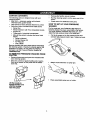
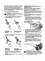
CARTON
•
CONTENTS
Raise guide handle, secure in place.
Roll the cleaning system out the open end of the
carton.
The tollowing parts are shipped loose with your
cleaning system:
• Main Unit -- pressure washer with wheels,
chemical tanks, guide handle.
• High Pressure Hose (already attached to pump)
• Parts Box (which includes items listed below)
• Spray Gun
• Wand Extension with Hi/Lo Adjustable Nozzle
• Engine Oil
Three-pack of chemical concentrates
• Manual Bag (which includes the items listed
below)
• Owner's Manual
• Nozzle Cleaner Kit
• "O"-Fling Kit
• Tank Labels
•
Check carton for additional loose parts
HOW TO SET UP YOUR PRESSURE
WASHER
For the most part, your Craftsman High Pressure
Cleaning System has been assembled at the factory
You must, however, assemble the spray gun, and
attach the high pressure hose to the spray gun
•
Cut the tie wraps on the high pressure hose and
connect high pressure hose to gun Tighten by hand
•
Attach nozzle extension to spray gun
Become familiar with each piece before assembling
the cleaning system Check all contents against the
illustration on Page 5 If any parts are missing or
damaged, call the Pressure Washer Helpline at
1-800-222-3136.
TO REMOVE
CARTON
•
•
PRESSURE
WASHER
FROM
Remove loose parts and parts box included with
your cleaning system.
Slice two comers at guide handle end of carton
from top to bottom so the panel can be folded
down flat
Place assembled spray gun on holder
Uft the handle to
upright position and
slide the locking
caps into place
4
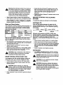
KNOW
YOUR
HIGH
PRESSURE
WASHER
Read this owner's manual and safety rules before operating your cleaning system. Compare the
illustrations with your cleaning system to familiarize yourself with the ocations of various controls and
adjustments.
Gas Cap
k
Detergent and Chemical
Reservoirs with Filter &
Baffle
System Rinse
Reservoir
\
Spray Gun
/
Water Inlet
Air Filter
Dial-A-CleanerTM
Selector Knob
Choke Lever
0il Fill Cap
High Pressure Hose
Adjustable Nozzle
Pump
Pressure
CommendTM
Adjustable Nozzle - Adjust for high or low nrassure;
narrow or fan spray.
Oil Fill Cap - Fill engine with oil here. See page 7 for
oil recommendations.
Air Filter - Dry type filter element limits the amount of
dirt and dust that gets in the engine.
Pressure Command
Choke Lever - Used to start a cold engine.
Spray Gun - Controls the application of water onto
cleaning surface with trigger device. Includes safety
latch.
TM
- Sets output water pressure.
Pump - Develops high pressure water.
Dial-A-Cleaner TM Selector Knob - Selects any one
of three chemicals or selects the clean water system
rinse.
Gas Cap - Fill engine with regular unleaded gasoline
here.
System Rinse, Detergent and Chemical Reservoirs
- Used to provide detergent or other chemicals to the
low pressure water stream.
High Pressure Hose - Connect one end to the spray
Water Inlet - Connection for garden hose.
gun.
5
HOW TO USE YOUR
CLEANING
SYSTEM
Cleaning With The Adjustable Nozzle and
Applying Chemical
Read these instructions and learn how to use your
cleaning system before you attempt to start your
cleaning system. If you have any problems operating
your cleaning system, please call the pressure washer
helpline at 1-800-222-3136.
IMPORTANT: Use soaps designed specifically for
pressure washer cleaning systems. Household
detergents could damage the pump.
IMPORTANT: You must attach all hoses before you
start the engine. Starting the engine without all the
hoses connected and without the water turned ON will
damage the pump.
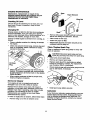
How To Use the Adjustable Nozzle
A
•
Up to three (3) different solutions can be carried on
the cleaning system at one time. To apply detergent
follow these steps:
ARNING:
Never
spraying.
Never
put adjust
hands spray
in frontpattern
of the when
nozzle
when adjusting the spray.
Push the nozzle forward for low pressure_ Pull the
nozzle backward until it "snaps" into place {o
achieve high pressure.
•
Dilution is necessary when using the supplied
chemical packets. Simply snip one comer of the
plastic pouch, pour the chemical into the tank, then
fill the tank with clean water. Label tanks with the
provided tank labels.
Pour chemical into one of
the tanks labeled A, B, C.
Pull nozzle
backward for high
pressure.
•
If using another chemical designed for use with
pressure washers, prepare the chemical solution as
required by the chemical manufacturer. Fill
chemical reservoir(s) with the prepared solution as
needed.
Push nozzle forward
for low pressure.
Twisting the nozzle adjusts the spray pattem from a
narrow to a =fan" pattern.
•
Rotate the DiaI-A-CleaneF" selector knob to the
letter corresponding to the desired reservoir.
•
Push the adjustable nozzte forward to tow pressure
mode. Detergent cannot be applied with nozzle
in high pressure position.
•
Review the use of the adjustable nozzle.
•
Connect garden hose to water inlet, check that
high pressure hose is connected to spray gun and
pump (see ASSEMBLY on page 4), and start
engine.
Connect garden hose here.
Twist nozzle
clockwise for
narrow spray.
Twist nozzle
counterclockwise for
"fan" pattern.
For most effective cleaning, keep spray nozzle
between 8 to 24 inches away from cleaning
surface.
CAUTION:
System, make
Before
surestarting
you have
your
read
Cleaning
and followed
the instructionsin the sections =Before Starting
the Cleaning System" on page 7 and "To Start
the Cleaning System" on page 8.
Damage to the surface may occur if you get spray
nozzle too close to it.
6
,_
Warning:
Besystem
extremely
careful
if you
must use
the
cleaning
from
a ladder,
scaffolding
or any other relatively unstable location. When
you press the trigger, the recoil from the initial
spray could force you to fall, or if you are too
close to the cleaning surface, high pressure
could force you off a climbing apparatus.
•
•
Rotate the Dial-A-Cleaner TM selector knob to the
letter corresponding to the System Rinse tank. As
clean rinse water is drawn through the system,
continue the flow until no detergent foam is
observed.
Rotate the Dial-A-Cleaner
OFF position.
TM
selector knob to the
•
Start at lower portion of area to be washed and
work upward, using long, even overlapping strokes.
BEFORE
SYSTEM
•
Allow detergent to 'soak in' (between 3-5 minutes)
before washing and rinsing. Reapply as needed to
prevent surface from drying.
To operatette engine you willneed to do the following:
Only use high quality detergent oil rated with API
service classification SF or SG. Select the oil's SAE
viscosity grade according to your expected operating
temperature:
This Craftsman Cleaning System permits regulatLonof
output water pressure by varying the engine speed.
The Pressure Command TM found on the front panel
may be set, as follows:
Low
Light
Auto
to
_
Medium
Concrete
High
Heavy
Paint removal
Boat
Furniture
Driveway
Deck
Degreasing
colder
Adjust Pressure Command TM control to obtain
desired water pressure.
•
Expand the spray pattern for a more gentle rinsing
action. Start at top of area to be dnsed, working
down with same action as for cleaning.
._
warmer
SAE 30
Although multi-viscosityoils (5W30, 10W30, etc.)
improve starting in cold weather, these multi-viscosity
oils will result in increased oil consumption when used
above 32°F. Check your engine oil level more
frequently to avoid possible damage from running low
on oil.
Place pressure washer system on a level surface
Clean area around oil fill and remove oil dipstick.
Pour oil from enclosed bottle into the oil fill opening
until oil reaches the full mark on the oil dipstick.
Stop and check the oil level periodically. Do not
overfill.
•
Install oil dipstick, hand tighten securely.
Add Gasoline
•
,_
32°F
I
Pull adjustable nozzle backward until it snaps to get
high pressure mode. Chemical will not flow when in
the high pressure mode.
•
-<----5W30
After you have applied detergent, scour the surface
with the high pressure water stream and then dnse it
clean, as follows:
•
THE CLEANING
Add Engine Oil
Wash and Rinse Surface
Pressure
Duty
Application
STARTING
CAUTION:
area is
of no
thedamage
surface to
be cleaned. Test
Makea small
sure there
caused by the high pressure spray.
Use regular unleaded gasoline with the cleaning
system engine. Fuel tank capacity is 3 U.S, quarts.
RINSE SYSTEM AFTER EVERY'USE
,_
DANGER:
Never
fill fuel
tank indoors.
fill
fuel
tank when
engine
is running
or hot.Never
Do not
smoke when filling fuel tank.
it is imperative that the chemical selector system be
rinsed after each use to prevent clogging or leaks:
• Fill the System Rinse reservoir with clean water.
A
AUTION:
Do expansion.
not overfill the fuel tank. Always
leave
room for
,_
CAUTION:
Experience
indicates
that alcohol
blended fuels
(called gasohol
or using
ethanol
or methanol) can attract moisture which leads to
separation and formation of acids during
storage. Acidic gas can damage the fuel system
of an engine while in storage.
•
A
•
Before disconnecting the water supply, siart your
cleaning system.
CAUTION:
Before
your
Cleaning
System,
make
surestarting
you have
read
and followed
the instructions in the sections =Before Starting
the Cleaning System" on page 7 and =To Start
the Cleaning System" on page 8.
Push adjustable nozzle forward to get.low pressure
mode.
7
Toaddfueltoengine:
•
Clean area around fuel cap, remove cap.
•
Add regular unleaded gasoline, slowly, to the fuel
tank.
Important: Never mix oil with gasoline.
•
Install fuel cap and wipe up any spilled gasoline.
TO START THE CLEANING
SYSTEM
Safety Latch
The best way to start your cleaning system engine for
the first time is to follow these instructionsstep-bystep. This starting information also applies whenever
you start the engine after you have let the cleaning
system sit idle for at least a day.
•
•
Attach adjustable nozzle extension onto spray gun.
•
Pull choke lever all the way out to the =FULL
CHOKE POSITION."
Place the cleaning system in an area close enough
to an outside water source that can flow at ;_ rate of
at least 3 gallons per minute. Connect a garden
hose to the water spout.
•
Check that the high pressure hose is tightly
connected to the spray gun and to the pump. See
ASSEMBLY section on page/4.
•
Check inlet screen on the water inlet. If the screen
is dirty, clean before attaching a garden hose. If the
screen is damaged, do not connect to the garden
hose. Replace with screen provided in maintenance
kit or call 1-800-366-PART to order a replacement
inlet screen.
•
•
Attach the the garden hose to the water inlet.
Tum on the water.
Choke Lever
in =Full Choke
Position"
Note: If restarting a warm engine after a short
shutdown, move choke lever to =NO CHOKE
PosmoN."
Important: Do not run pump without the water supply
connected and turned on. You must follow this
caution or the pump will be damaged.
• Remove the adjustable nozzle extension from the
spray gun.
•
Pull the trigger on the spray gun and hold until a
steady stream of water appears.
•
Engage the safety latch on the spray gun.
•
8
Move Run/Stop switch to the "1" or on position.
•
Grasp starter handle and pull slowly until you feel
some resistance. Then pull cord rapidly to
overcome compression, prevent kickback and start
the engine. Let rope return to starter slowly.
Note: The Pressure Command TM may be placed in
any position during starting or operation.
• When engine starts, move choke lever to "1/2
CHOKE" until engine runs smoothly and then to
"NO CHOKE POSITION." If engine falters, move
choke lever to =1/2 CHOKE" until engine runs
smoothly and then to "NO CHOKE POSITION."
•
Simply shutting off the engine will not release
pressure in the system. Squeeze trigger on the
spray gun to relieve pressure in the hose.
SIPHONING
We recommend that you DO NOT siphon standing
water for your water supply. Contaminated, brackish or
dirty water can damage the pump. Connect only to
household water supply.
Note: If engine fires, but does not continue to run,
move choke lever to "FULL CHOKE" and repeat,
starting instructions.
TIPS
Once the engine has started, disengage the slSray
gun safety latch.
HOW TO STOP YOUR
WASHER
Move the Run/Stop switch to the "0" or OFF
position.
Note: A small amount of water will squirt out when
you release the pressure.
• Rotate the Dial-A-Cleaner TM selector knob to the
OFF position to prevent chemical leakage.
Note: If the engine fails to start after 3 pulls, move
choke lever to "NO CHOKE POSITION" and pul!
starter rope again.
•
•
PRESSURE
Important: Do not run pump without the water supply
connected and turned on. You must follow this caution
or the pump will be damaged.
9
•
Never use the garden hose inlet to siphon
detergent or wax.
•
If you hold the spray nozzle too far away from the
object being cleaned, washing will not be as
effective.
•
Always store the cleaning system with the Dial-ACleaner TM selector knob at the OFF position.
CUSTOMER
RESPONSIBILITIES
HOURLY OPERATING
INTERVAL
MA|t_RENANCESCHEDULE
RLL iN DATESAS YOU COMPLETE
REGULARSERVICE
Before
MAINTENANCE TASK
Es_tl
Use
J
HOURS or
Hours
Eve/'] 50
Yearly
SERVICE DATES
O_
Evee/100
Yearly
PRESSURE WASHER
Check/clean water inlet screen
onquick-connect.
Checkhighpressure
hose.
xt
x
Check detergent hose,
x
Check spray gun and assembly for leaks.
x
Purgepumpofairandconterninants.
ENGINE
Checkoillevel.
x
'
x
x*
oil.
Serviceair cleaner.
Change engine
x'*
x
unitforstorageif itisto
remainidlefor longer than30 days.
Clean/replace spark plug.
Prepare
Prepare for storage.
"t C_ean i1 clogged. Re_
if perforated or torn.
Change oil after the first (2) opera_ng hours and every 50 hours thereafter.
Change sooner when operating under dirty or dusty
conditions.
"* Replace more often under dirty or dusty conditions.
PRODUCT
SPECIFICATIONS
In the State of California a spark arrestor is required
by law (Section 4442 of the Califomia Public
Resources Code). Other states may have similar laws.
Federal laws apply on federal lands.
Pressure Washer Specifications
PRESSURE
2250 psi
FLOW RATE
2.5 GPM
CHEMICAL
MIX
WATER SUPPLY
TEMPERATURE
Note: if you equip the engine of your cleaning system
with a spark arrestor muffler, the spark arrestor must
be maintained in effective working order by the
owner/operator.
Use as directed
You can order a spark arrestor (P/N 36085) through
your Sears Service Center.
Not to Exceed 140°F
GENERAL
The warranty of the cleaning system does not cover
items that have been subjected to operator abuse or
negligence. To receive full value from the warranty,
operator must maintain cleaning system as instructed
in this manual.
Engine SpecificaCdons
ENGINE
MODEL
RATED HORSEPOWER
SPARK PLUG: Type:
GASOLINE
CAPACITY
OIL
SOLID STATE
IGNITION AIR GAP
RECOMMENDATIONS
Tecumseh
6
Champion RN4C
or equivalent. Set
Gap to:0,030 inch
(0.76mm)
Some adjustments wilt need to be made periodically to
properly maintain your cleaning system.
All adjustments in the Service and Adjustments
section of this manual should be made at least once
each season.
3 U.S. quarts
Once a year you should clean or replace the spark
plug and replace the air filter and check the gun
and wand assembly for wear. A clean spark plug
and new air fitter assure proper fuel-air mixture and
help your engine run better and last longer.
SAE 30 weiaht
0.(_125 inch
10
BEFORE
EACH
USE
•
Check water inlet screen for damage.
•
Check high pressure hose for leaks.
•
Check chemical tanks and filters for damage.
•
Check gun and wand assembly for leaks.
Purge pump of air and contaminants.
•
Check engine oil level.
PRESSURE
WASHER
Check and Clean
If the screen is damaged, the o-ring kit contains a
replacement in-line filter screen and an o-ring. If
undamaged, reuse screen.
3. Place the in-line filter screen into the threaded end
of the lance. Direction does not matter. Push the
screen in with the eraser end of a pencil until it
rests flat at the bottom of the opening. Take care to
not bend the screen.
2.
4. Place the o-ring into the recess. Push the o-ring
snugly against the in-line filter screen.
MAINTENANCE
5. Assemble the lance to the spray gun, as described
eadier in this manual.
Inlet Screen
Examine garden hose inlet screen. Clean if it is,
clogged or replace if it is tom.
Purge Pump of Air and Contaminants
Check High Pressure Hose
High pressure hose can develop leaks from wear,
kinking, or abuse. Inspect hose each time before tJsing
it. Check for cuts, leaks, abrasions, bulging of cover,
or damage or movement of coupl!ngs. If any of these
conditions exist, replace hose immediately.
,_
DANGER:with
Never
a high
hose.
Replace
hoserepair
with one
thatpressure
meets the
minimum pressure rating of the system.
Check Chemical Reservoirs
To remove the air from the pump, follow these steps:
• Set up the cleaning system as described in the
ASSEMBLY section and connect the water supply.
•
Remove the wand extension from the gun.
•
Pull the trigger on the gun and hold until a steady
stream of water appears.
To remove the contaminants from the pump, follow
these steps:
•
Set up the cleaning system as described in the
ASSEMBLY section, and connect the water supply.
•
Remove the nozzle attachment from the gun.
•
Start the engine according to instructionsin
OPERATION section.
Tank covers should snap cleanly onto tank. Ensure
chemical labels correctly identify tank contents.
Ensure that the System Rinse tank is filled with clean
water. Ensure that Dial-A-Cleaner TM selector knob
rotates freely between each position. Examine the
tanks and replace if the filter is clogged
Pull the trigger on the gun and hold.
When the water supply is steady and constant,
engage the safety latch and refasten the nozzle
attachment.
Nozzle Maintenance
Check Gun and Wand
If the nozzle becomes restricted or clogged with
foreign materials, such as dirt, excessive pump
pressure may develop. A partially clogged nozzle can
cause a pulsing condition during use. This generally is
not a pump related problem, but rather a clogged or
partially restricted nozzle.
Examine hose connection to gun and make sure it is
secure. Test trigger by pressing it and making sure it
springs back into place when you release it. Put safety
latch in UP position and test trigger. You should not be
able to press trigger. Replace gun immediately if it
fails any of these tests.
If the nozzle becomes clogged or partially restricted,
immediately clean the nozzle with the kit included with
your cleaning system by followingthese instructions:
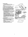
Check In-Une Filter
Refer to the illustration and service the in-line filter if it
becomes clogged, as follows:
Shut off the engine and tum off the water supply.
In-Line Filter
•
Separate the wand from the gun.
•
Rotate to stream setting.
•
Remove nozzle from the end of the wand using a
2mm or 5/64 allen wrench.
\
1. Detach gun and lance from high pressure hose.
Detach lance from gun and remove o-dng and
screen from lance. Flush the screen, gun, and
lance with clean water to clear debris,
11
Usethewireincludedinthe kitor a small paper
Parts in the O-Ring ICJtInclude:
clip to free the foreign materials clogging or
restricting the nozzle.
•
1 O-ring, red, (p/n B2726) for the end of the spray
gun connection between gun and highJ1owspray
wand.
•
2 O-rings, yellow, (p/n B2264) for the ends of the
high pressure hose.
Insert wire into nozzle and turn back and forth to
clear obstruction.
Remove additional debris by back flushing water
supply through wand. Back flush between"30 to 60
seconds. Turn wand to stream spray and move
nozzle from low to high pressure while flushing.
•
Reinstall nozzle into wand. DO NOT overtighten.
•
Reconnect wand extension to spray gun.
•
Reconnect the water supply, rum ON the water,
and start the engine.
•
Test the cleaning system by operating with nozzle
in the high and the low pressure positions.
Note: The above two o-rings are close in size.
Please match carefully to assure proper o--,ring
usage.
• 1 rubber washer (p/n B2385) for the inside of the
garden hose connector.
• 1 water inlet screen (p/n B2384) for the garden
hose connector.
O-Ring Maintenance
Through the normal operation of your cleaning
system, the o-rings keep the connections of the hoses
and gun tight and leak-free. They may become worn
or damaged with use. Provided with your cleaning
system is an O---ring Maintenance Kit containing
replacement o-rings, a rubber washer and a garden
hose inlet screen.
To remove a worn or damaged O-Ring:
•
12
Use a small flathead screwdriver to get
undemeath the o-ring and pry it off.
ENGINE
MAINTENANCE
Base
Maintenance, replacement or repair of the
emission control devices and systems may be
performed by any non-road engine repair
establishment or individual.
Paper Element
Checldng Oil Level
Oil level should be chocked prior to each use or at
least every 5 hours of operation. Keep oil level
maintained.
Bas_
Changing Oil
Change engine oil after the first two hours and ,every
50 hours thereafter. If you are using your cleaning
system under extremely dirty or dusty conditions, or in
extremely hot weather, change oil more often.
•
Change oil while engine is still warm from running,,as
follows:
•
Place a suitable container for draining oil beneath
the engine.
•
Clean area around oil drain plug, remove plug and
drain oil completely. When crankcase is empty,
reinsta, oil drain plug.
•
•
t_ '__(_Wing
Nut
Remove dirty paper element carefully to prevent
debris from failing into carburetor. Discard,
Clean inside of filter case.
Install new paper air filter.
Reassemble all parts and fasten securely to the
carburetor with the wing nut.
Clean / Replace
Spark Plug
Clean or replace the spark plug yearly or every 100
hours of operation.
A
CAUTION:
Disconnect
spark
plug
wire
fromplug.
spark plug and
keep wire
away
from
spark
•
Clean area around spark plug.
•
Remove and inspectspark plug.
•
Replace spark plug if the electrodes are pitted,
burned or porcelain is cracked. For replacement
use Champion RN4C or equivalent.
•
Check electrode gap with wire feeler gauge and set
gap at .030 inches, if necessary.
•
Install spark plug, tighten securely.
Clean area around oil fill plug and remove the oil
dipstick. Fill engine crankcase with recommended
oil until oil level is is at the full mark on the dipstick.
POUR SLOWLY.
When engine crankcase is filled to proper level,
install and tighten oil dipstick.
Sen/me Air Cleaner
Your engine will not run properly and may be
damaged if you run it with a dirty air cleaner.
Replace the air cleaner once every 100 hours of
operation or once each year, whichever comes first.
Replace more often if operating under dirty or dusty
conditions. Do not attempt to clean or oil filter.
Replacements are available at your local Sears
Authorized Service Center.
Carburetor
If you think your carburetor needs adjusting, see your
nearest Sears Service Center. Engine performance
may be affected at altitudes above 4000 feet. For
operation at higher elevations, contact your nearest
Sears Service Center.
To clean or replace the air cleaner, follow these steps:
•
Remove wing nut on the air cleaner cover.
13
AFTER EACH USE
Flush the chemical system by selecting a tank and
run the Pressure Washer with nozzle in low
pressure mode. Flush until each tank is empty, then
switch the selector knob to the next tank. The last
tank to be emptied must be the System Rinse tank.
Water should not remain in the unit for long periods of
time. Sediments of minerals can deposit on pump
parts and "freeze" pump action. Follow these
procedures after every use:
•
Flush the chemical system by selecting the System
Rinse tank and run the Pressure Washer with
nozzle in low pressure mode. Flush for one minute
or until the chemical is cleared from the system.
•
Shut off the engine and let it cool, then remove all
hoses.
,_
•
•
•
CAUTION:
is
in the 'O' or
BeOFF
sureposition
the engine
before
Run/Stop
you continue.
switch
Empty the pump of all pumped liquids by pulling
recoil handle about 6 times with the Run/Stop
switch in the '0' or OFF position.This should
remove most of the liquid in .the pump.
Rotate the Dial-A-Cleaner TM selector knob to the
OFF position.
Connect a 3-foot section of garden hose to the inlet
adapter. Pour RV-Antifreeze (antifreeze without
alcohol) into the hose. Pull the recoil handle twice.
LONG TERM STORAGE
If you do not plan to use the Pressure Washer for
more than 30 days, you must prepare the engine for
long term storage.
It is important to prevent gum deposits from forming in
essential fuel system parts such as the carburetor, fuel
filter, fuel hose or tank dudng storage. Also,
ex_padencoindicates that alcohol-blended fuels (called
gasohol, ethanol or methanol) can attract moisture
which leads to separation and formation of acids
dudng storage. Acidic gas can damage the fuel system
of an engine while in storage.
Coil the high pressure hose and inspect it for
damage. Cuts in the hose or fraying could result in
leaks and loss of pressure. Should any damage be
found, replace the hose. DO NOT attempt to repair
a damaged hose. Replace the hose with the
genuine Craftsman part.
Protect
FueSystem
•
Drain water from hose and properly hang it on the
wire support provided.
•
•
Store system in a clean, dry area.
Remove all gasoline from the fuel tank to prevent
gum deposits from forming on these parts and
causing possible malfunction of engine.
•
Run engine until engine stops from lack of fuel.
Make sure you have water supply to pump inlet
connected and turned ON.
,_
the
DANGER:
gas tankNever
indoors
store
or in
theenclosed,
engine with
poody
fuel in
ventilated areas where fumes may reach an
open flame, a spark, or pilot light.
WINTER STORAGE
,_
DANGER:
Drainfrom
fusl open
into approved
outdoors, away
flame. Becontainer
sure
engine is cool. Do not smoke.
Change Oil
Whileengineis stillwarm, drainoilfromcrankcase.
Refillwith recommendedgrade.(See ChangingOil)
Oil Cylinder
,_
CAUTION:
You must protect
unit
freezing
temperatures.
Failureyour
to do
sofrom
will
permanently damage your pump and render
your unit inoperable.
•
To protect the unit from freezing temperatures:
•
,_
Empty al_ chemical reservoirs as followS:
a.
•
Disconnect hose connected to chemical inject
fitting on the pump. Place end of hose into
suitable container.
b.
Move the selector knob to Tank A and open
that tank's cover. Gravity should shortly empty
the tank contents into the container.
c.
When the tank is empty, repeat step (b) for
tanks B and C.
d.
Reconnect the hose to the chemical inject
fitting on the pump. Add 0.5 liter of clean fresh
water to each tank and close tank's covers.
Bore
Remove spark plug. Squirt about 1 ounce (30 ml) of
engine oil into the cylinder. Cover spark plug hole
with rag. Crank engine slowly to distribute oil.
when
CAUTION:
cranking
Avoid
engine.
spray from spark plug hole
Install spark plug. Do not connect spark plug wire.
OTHER
Do not store gasoline from one season to another.
If possible, store your unit indoors and cover it to
give protection from dust and dirt. BE SURE TO
EMPTY THE FUEL TANK.
IMPORTANT: NEVER cover your cleaning system
while engine and exhaust area are warm.
14
CAUSE
PROBLEM
CORRECTION
Pump has toilownng problems:
1. Nozzle in tow pressure mode.
1.
Pull nozzle backward for high
failure to produce pressure, or
erratic pressure, chattedng, loss of
2.
Water inlet is blocked.
2.
pressure mode.
Clear inlet
pressure, Lowwater volume.
3. Inadequate water supply
3.
Provide adequate water flow at
least 3 gpm.
4.
4.
Straighten inlet hose, patch leak.
5. Clogged water inlet screen.
5.
Replace / clean water inlet
screen.
6. Water Supply is over 140°F.
7. Outlet hose is blocked.
6.
7.
Provide cooler water supply.
Clear blocks in outlet hose.
8.
9.
8.
Replace outlet hose if leaking.
9.
Replace O-ring or gun if
Inlet hose is kinked or leaking
Outlet hese leaks.
Gun leaks.
10. Nozzle _ obstructed.
necessary.
10. Clear nozzle.
11. Pump is faulty.
11. Contact Sears Service
Department.
Detergent fails to mix.
1.
Detergent line is collapsed or
kinked
1.
Repair or replace detergent
line.
2.
3.
Chemical tank filter is clogged.
Nozzle is in high pressure mode.
2.
3.
Replace tank
Push nozzle forward for
4.
Dial-a-Cleaner knob is in off position.
4.
low pressure mode.
Rotate knob for desired chemical.
Engine runs good when not spraying
but dies when you begin to spray.
Engine speed is too slow.
Contact Sears Service Department.
Engine will not start; or starts
and runs rough
1. Dirty air cleaner
2. Out of gasoline.
3. Sta|e gasoline.
4. Spark plug wire not connected
1. Clean or replace air cleaner.
2. Fill fuel tank.
3.
4.
Drain gas tank; fill with trash fuel.
Connect wire to spark plug.
5,
6.
Replace spark plug,
Drain gas tank; fill with fresh fuel.
7.
Set engine throttle control lever to
to spark plug.
5,
Bad spark plug.
6.. Water in gasoline.
7. Overchoking or flooded
8.
Excessively rich fuel mixture.
9.
Intake valve stuck open or dosed.
fast position, choke in run position.
8. Contact Sears Service
9.
Department.
Contact Sears Service
10. Engine has lost compression.
Department.
10. Contact Sears Service
Fill fuel tank.
Replace Air filter.
Department.
Engine shuts down during
operation
1.
Out of gasoline.
1.
2.
Air filter dirty
2.
Engine lacks power.
Dirty air filter.
RepLase air filter.
15
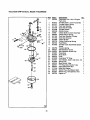
16
Tecumseh
6HP Enduro,
Model #143.996005
161
173
310 --
J
157
158
130
119
48
72
245
250A
/
25O
/
251
238
17
Tecumseh
65
6HP Enduro,
Model #143.996005
6O
342
\
292
25A
26
9O
37O4
313
285
261
I
26O
390
19
200~
210
1BS_'_
287
P
370K
18
Tecumseh
]_
2
14
15
16
19
20
25
25A
26
30
35
37
38
40
40
41
41
6HP Enduro,
37120A
26727
651052
37108
37110
37111
32600
36621
36622
30200
34740
651053
29216
37109
40004
40005
36070
36071
42
42
43
45
40006
40007
20381
32875A
46
48
49
50
60
64
65
69
70
72
75
80
81
82
83
86
89
90
92
93
100
101
103
103A
110
110A
111A
119
120
125
125
32610A
35616
36611
37040
36623A
651015
30200
36624
36766
27642
36742
30574A
30590A
30591
36057
650488
610961
611205
650815
650818
34443B
610118
651007
650767
35589
36964
611224
36719
36721
36471
36472
126
126
130
130A
135
150
151
29314(3
29315C
650912
650999
34645
37039
31673
Model #143.996005
otv.
Cylinder (Incl. 2, 20 & 72)
Dowel Pin
Washer
Governor Rod
Governor Lever
Extension Spring
Oil Seal
Air Baffle (Left)
Air Baffle (Right)
Screw, 10-24 x 9/16"
Crankshaft
Screw, Torx T-25, 10-32 x 63_84"
Lock Nut, 10-32
Retaining Ring
Piston, Pin & Ring Set (Std.)
,
Piston, Pin & Ring Set (.010" OS)
Piston & Pin Aas'y (Std.) (IncL 43)
Piston & Pin Ass'y
(.010" OS) (Incl. 43)
Ring Set (Std.)
Ring Set (.010"/OS)
Piston Pin Retaining Ring
Connecting Rod Ass'y
(Incl. 46 & 49)
Connecting Rod Bolt
Valve Lifter
Oil Dipper
Camshaft (Incl. 253 & 254)
Blower Housing Extension
Screw, 1/4-20 x 1-1/8"
Screw, 10-24 x 9/16"
Cylinder Cover Gasket
Cylinder Cover (Incl. 75 thru 83)
Oil Drain Plug
Oil Seal
. Governor Shaft
Washer
Governor Gear Ass'y (IncL 81)
Governor Spool
Screw, 114-20 x 1-1/4"
Flywheel Key
Flywheel
Bellevine Washer
Flywheel Nut
Solid State ignition
Spark Plug Cover
Screw, TorxT-15, 10-24 x 15/16"
Screw, 8-32 x 27/64" •
Ground Wire
Ground Wire
Rocker On/Off Switch
Cylinder Head Gasket
Cylinder Head
Exhaust Valve (Std.) (IncL 151)
Exhaust Valve (1/32" OS)
(Incl. 151)
Intake Valve (Std.) (Incl. 151)
Intake Valve (1/32, OS) (incl. 151)
Screw, 5/16-18 x 1-1/2"
Screw, 5/16-18 x 2-41/64"
Resistor Spark Plug (RN4C)
Valve Spring
Valve Spring Cap
1
2
1
1
1
1
1
1
1
1
1
1
1
1
1
1
1
1
1
I
2
1
2
2
1
1
1
1
1
1
1
2
1
"1
1
1
1
8
1
1
1
1
1
1
2
1
1
1
1
1
1
1
1
1
1
4
1
1
2
2
PaM#
153
154
t 55
157
158
159
160
161
161A
173
178
182
184
185
186
200
207
2O9
210
211
223
224
238
239
240
245
250
250A
251
252
253
254
260
261
261A
262
275
277
278
279
280
285
267
290
292
300
301
310
313
325
341
342
370A
370K
380
390
400
416
417
600
900
19
36649
650913
35624A
650914
36629
35626
36630A
651O08
651012
36675A
85O852
650451
26756
36631
36711
36736
36632
650821
27793
28942
650451
36581
28820
27272A
36633A
36046
37073
37074
650886
650821
36701
36702
36864
651008
650821
651008
36722
650988
36674
650852
36893
35985B
0
30705
26460
36863
36754
36678
34080
29443
36644
651010
36261
36695
640060
590736
36720
36085
650760
651013
NSP
• ti
uide
Rocker Arm Stud
2
Rocker Arm
2
Nut, 1/4-28
2
Push ROd
2
Rocker Arm Cover Gasket
1
Rocker Arm Cover
1
Screw, 1/4-20 x 31/64"
2
Stud
2
Breather Tube
1
Nut, 1/4-20
2
Screw, 1/4-20 x 1"
2
Carburetor To Intake Pipe Gasket
1
Intake Pipe
1
Govemcr Link
1
Control Bracket (Incl. 210 & 211)
1
Throttle Link
1
Screw, 10-32 x 1/2,
2
Conduit Clip
1
Screw, 10-32 x 3/8"
1
Screw, 1/4-20 x 1"
2
Intake Pipe Gasket
1
Screw, 10-32 x 1/2"
2
Air Cleaner Gasket
1
Air Cleaner Body (Incl. 239)
1
Air Cleaner Filter
1
Air Cleaner Cover
1
Air Cleaner Baffle
1
Wing Nut
1
Screw, 10-32 x 1/2"
1
Compression Release Weight
1
Compression Release Spring
1
Blower Housing
.
1
Screw, 1/4-20 x 31164
1
Screw, 10-32 x 1FZ"
2
Screw, 1/4-20 x 31/64"
2
Muffler
1
Screw, 1/4-20 x 2-9132"
2
Spacer
1
Nut & Lock Washer
1
Heat Shield
1
Starter Cup
1
Rivet (Can be purchased _ocally)
4
Fuel Line
1
Fual Line Clamp
2
Fuel Tank (Incl. 292 & 301)
1
Fuel Cap (Black)
1
Dipstick
1
Spacer
1
Wire Clip
1
Fuel Tank Bracket
1
Screw, 114-20 x 7/8"
2
identification Decal
1
Starter Decal
1
Carburetor (Incl. 184)
1
Rewind Starter
1
Gasket Set (IncL items Marked PK 1
in Notes) Incl. (1) each of 26756,
27272A, 29673, 35626, 36581, 36624,
36719
Spark Arrestor Kit (Incl. 417)
1
Screw, 8-32 x 3/6`
1
Washer
1
Replacement engine - None
0
Tecumseh
6HP Enduro,
Model #143.996005
Item Pa_#
0
640O6O
2
'20A
]
30
_b_.37
.dD_37
- 25
20
1
2
4
5
6
7
10
11
12
13
14
15
16
17
631615
631767
631184
631183
631036
650506
31868
632042
631184
631183
631890
630735
632164
651025
18
20
20A
25
27
28
29
30
31
36
37
40
44
47
48
60
630766
640027
640053
631867
631024
632019
631028
631021
631022
640019
632547
640015
27110A
630748
631027
832760
Carburetor (Incl. 184 of Engine
Parts List)
Throttle Shaft & Lever Assembly
Throttle Retum Spring
Dust Seal Washer
Dust Seal (Throttle)
Throttle Shutter
Shutter Screw
Choke Shaft & Lever Assembly
Choke Return Spring
Dust Seal Washer (Choke)
Dust Seal (Choke)
Choke Shutter
Choke Positioning Spring
Fuel Fitting
Throttle Crack Screw/Idle Speed
Screw
Tension Spring
Idle Restrictor Screw
Idle Restrictor Screw Cap
Float Bowl
Float Shaft
Float
Float Bowl =O_ Ring
Inlet Needle, Seat & Clip (Incl. 31)
Spring Clip
Main Nozzle Tube
=O" Ring, Main Nozzle Tube
High Speed Bowl Nut
Bowl Nut Washer
Welch Plug, Idle Mixture Well
Welch Plug, Atmospheric Vent
Repair kit
1
1
1
1
1
1
2
1
1
1
1
1
1
1
1
1
1
1
1
1
1
1
1
1
1
2
1
1
1
1
1
Tecumseh
6HP Enduro,
Model #143.996005
_em Pa_#
0
1
2
3
4
5
6
7
8
11
12
13
F
21
590736
590599A
590600
690696
590601
590697
590698
590699
590700
590705
59O535
59O701
Qty.
Rewind Starter
Spring Pin (Incl. 4)
Washer
Retainer
Washer
Brake Spring
Starter Dog
Dog Spring
Pulley & Rewind Spring Ass'y.
Starter Housing Ass'y.
Starter Rope (98" x 9/64" dia.)
Starter Handle
1
1
1
1
1
1
2
2
1
1
1
1
Craftsman
Pump
2250 PSI Cleaning
System 580.768030
oL
42
L
,
13
13,1
48
13
48
16
38
oo
0
_
41
0
17
22
Craftsman 2250 PSI Cleaning System 580.768030
Pump
Nern Part#
Qtv Descr_bn
Item Pad#
1
B2218
1
O-RING, 1.625"x 0.103
33
...
2
3
4
5
6
7
8
9
10
11
12
B2260
B2217
B2261B
96400
99735
93790
40945
93652
95416
93876
A2069
1
4
4
3
1
1
6
1
1
1
1
ADAPTER, Engine
O-RING, 0239 ID x 0.0-/0
SCREW, ButtonHd 5/16 - 24 x 3/4" Lg
SPRING, PistonReturn
ASSEMBLY,Oil Bmalher
O-RING, 114x 119x 2.6
SHCS, M6 x 1.0 x20mm Lg
SPRING, ThermalBy-Pros '
P_STON,_
By-Pass
O-RING, Z9 x 6.5 x 1.78
GASKET,Head
34
13
93644
1
ACTUATOR,
Thern_ By-Pass
14
15
16
17
18
19
20
21
22
96053
96015
B2665
A2013
97840
97841
B4178
......
......
3
3
6
6
3
3
0
2
1
SEAL,_
Pressure
RING, Bear_g
WASHER, Steel Special
BOLT, Head M8 x 1.25x 70ram Lg
O-RING, Cap 15.6 x 19.16 x 1.78
CAP, _
Port
1_3T,
A,_J Ca_ 3/4"- 6.0 L_
BEARI_ SET,-nlI_ 15.5
CAM,A_ 7.5"Ut
46
47
48
49
50
23
......
1
ADAPT_ F=,_he
_t
24
25
26
28
29
30
31
32
......
......
......
B3478
......
......
B3508
......
1
1
1
0
3
3
0
3
WA..q--E_Thlust
RET,NNt_ Push-On
_
Ca-nRetaha"
KIT, Piston/Shoe
ASSY. Cea'Nc Pbton& Cap
SHOE, PistonPivot
KIT, Crankcase
SPACER, PiJot
Cnv De_r_on
. , ,...
3
1
SEAL O_ Piston
_Pump
35
B3509
o
_', spacerPtae
3_
......
37
......
38
B3513
39
......
40
. .....
1
3
0
6
6
SPACER, IHSt Plate
SEAL, High Pressure Dbl. Lip
KIT, Check Valve
ASSY. Ched<Va_
O-F_IG,CheckVabe 124x 1556x 1.78
41
134179
o
KIT,Urt_der Spinde
42
......
43
......
44
......
S_-I"8CI_--W,M6x8 Lg
SUPPORT, Unloader Spring
SPRING,Unloader
/_'Y, Spindle
KIT, Head
ASSY, Rrap Heed(M_ Rame)
KIT, High Pressure Outlet
O-RING, Spindle 6 x 10 x 1.78
SEAT, _ Unloader
BALL, Stainless Steel 9/32 Dia.
SEAT, Trapped Une Pressure
O-RING, 3.68 x 7.24 x 1.78
VALVE, Shuffle Piston
,.,
51
.....
52
.....
54
.....
1
1
1
0
1
0
1
1
1
1
1
1
55
56
57
.....
.....
.....
1
1
1
SPRNG, Fmm TrappedFlessum
VENTURI, Chemical
O-RING, Ventud 10.82 x 14.38 x
1.78
0
I
1
ASSY., Chemical injector
BARB HOSE, Brassw_h Ny_n Ins_
BALL,5.5 cia.Cher_cal k_ector
I
SPRING,Ohe_
O
0
KIT,Complete Head
KIT,O-Ring/Seals
45
58
59
60
61
62
63
......
=B3507
......
B4180
.....
.....
B4183
......
......
......
B4182
B4181
In_ctor
Item numbers 20, 28, 31, 35, 38, 41, 46, 48, 58, 62, and 63 are sewice kits and include all parts shown within
the box. Items previously described are not listed under the service kit number.
23
Craftsman
Main Unit
2250 PSI Cleaning
System
580.768030
41
24
Craftsman
Main Unit
2250 PSI Cleaning
Item Part_#
System
580.768030
Qtv
2
3
4
5
B3608C
B3597
B3376B
B32?.2D
1
1
1
1
6
7
B3222A
B3594
8
9
10
11
12
13
14
15
16
17
18
19
20
21
22
23
24
25
26
B3222B
B3222C
B3695
EB3265
96307
86292
B3311
B3721
B3377
EB3113
91526
49226
51716
B3306
B3593A
B3593B
B3593C
B3593D
B3601D
1
1
8
1
1
4
1
1
3
1
2
2
2
1
1
1
1
1
1
27
28
29
48031G
EB2555
B2071
1
2
30
31
46476
31669
2
1
32
33
34
35
36
37
38
39
B1779
B2347
B1460
B2759
B3741
B1760
75402
52858
2
2
1
1
1
2
2
2
LINK, Throttle Control
DECAL, Control Panel 2250
TAG, System Flush Water
CAP, Chem Container
"Water"
CAP, Chem Container =A"
ASSY., Chemical Tank 1/2
Gal.
•,
CAP, Chem Container "B"
CAP, Chem Container "C"
BOLT, 1/4"- 20 with Washer
CRADLE, Polo Green
DECAL, 1-800 Number
SELF DRILL, 10 - 16 x 3/4"
SCREW, Plastite 10- 9
HANDLE, 4-Way Valve
SCREW, Plastite 8 - 11 3/4"
PANEL, Control Polo Green
SCREW, M5 - 0.8 x 12
LOCK WASHER, M5
NUT, Hex M5 - 0.8
ASSY., Sub 4-Way Valve
HOSE, "A" - 6.5"
HOSE, =B" - 8.5"
HOSE, =C" - 11.0"
HOSE, "Water" - 8"
HOSE, Chemical Pump
10.5"
CLAMP, Hose 3116"
HANDLE, Polo Green
NUT, 1/4' - 20 Flange
Locking
CAP PLUG, Tubing
BOLT, 1/4"-20 x 1-3/4"
Carriage
COVER, Hinge
END CAP, Tube
CAP, Vinyl Black
HOOK, Square Neck Gun
AXLE ROD, 1/2" ,x 21.53"
ASSY., Wheel & Tire 10"
PUSHNUT, 1/2"
NUT, M8 - 1.25 Locking
item
40
Part_#
27007
Qtv
2
41
42
43
44
50190
42909
97100
21424
2
2
1
1
45
46
47
48
B3700D
A1408
21217
67989
1
1
4
8
49
52
53
54
55
56
57
58
59
60
61
62
63
64
900
92659
B3607
97566
B3335B
B3263
AB3061B
B3708
B2730
B3454
B3589
B3595
B3453
48031C
B1288
NSP
1
1
1
1
1
1
1
1
1
1
1
1
2
1
1
MOUNT, Vibration Donut
Type
FLAT WASHER, M8
HHCS, M8 x 1,25 x 30 Long
CAP, Outlet
CONNECTOR, Garden
Hose
ASSY., Pump
CAP, Inlet
MOUNT, Rubber Shock
NUT, Hex Locking Flange
M8
NOZZLE, Replacement
HOSE, 1/4" x 25'
TAG, Nozzle Instructions
WAND, Nozzle Hi/Lo
GUN, High Pressure
OIL BOTTLE, 20 oz
KIT, Cleaning Nozzle
KIT, Maintenance
KIT, Tag
KIT, 3 Pak Concentrate
MANUAL
DECAL, Start Instructions
CLAMP, Hose 1/2"
TAG, Breather
ENGINE
Optional Accessories Not Illustrated:
71-74300
House Wash Concentrate
71-74301
Deck Wash Concentrate
71-74302
Vehicle Wash Concentrate
71-74303
Degreaser Concentrate
71-74400
Heavy Duty Turbo Nozzle
71-74401
25' 3/8" Replacement Extension Hose
71-75115
25' 1/4' Replacement Hose
71-75116
0 Ring Repair Kit
71-75187
Garden Hose Quick Connect
71-75197
Accessory Quick Connect Kit
71-75199
Rotating Brush
71-76430
Floor/Siding Brush
71-76431
Utility Brush
25
CALIFORNIA & US EPA EMISSION
CONTROL WARRANTY
STATEMENT
You are responsible for presenting your utility or lawn or
garden equipment engine to a Tecumseh Authorized
Service Outlet (any Tecumseh Registered Service Dealer,
Tecumseh Authorized Service Distributor or Tecumsoh
Central Warehouse Distributor) as soon as a problem
exists. The warranty repairs should be completed in a
reasonable amount of time, not to exceed 30 days.
The U.S. Environmental Protection Agency ("EPA"), the
Calitomla Air Resources Board ("CARB") and Tecumseh
Products Co. are pleased to explain the Federal and
Caiifomia Emission Control Systems Warranty on your new
utilityor lawn and garden equipment engine. In California,
new 1995 and later utility and lawn and garden equipment
engines must be designed, built and equipped to meet the
State's stringent anti-smog standards. In other state,s, new
1997 and later model year engines must be designed, built
and equipped, st the time of sale, to meet the U.S. EPA
regulations for small no-road engines. Tesumseh Products
Co. will warrant the emission control system on your utility
or lawn and garden equipment engine for the time pedods
listed below, provided there has been no abuse, neglect,
unepproved modification, or improper maintenance of your
utilityor lawn end garden equipmen_ engine.
Warranty Service can be arranged by contacting either a
Tecumseh Authorized Service Outlet or by contacting
Tecumseh Products Co., c/o Service manager, Engine and
Transmission Group Service Division, 900 North Street,
Grafton, WI 53024-1499. Telephone 1-414-377-2700, or
see your local telephone yellow pages under "Engines,
Gasoline" for the name, address and telephone number of a
Tecumseh Authorized Service Outlet near you.
Important Note
This warranty statement explains your rights and obligations
under the Emission Control Warranty ('ECS Warranty")
which is provided to you by Tecurnseh Products Co.
pursuant to California law. Tecumseh Products Co. also
providesto the original purchasers of new Tecumseh
Products CO. engines. The Tesumseh Products Co. Limited
Warranties for New Teeumseh Engine and Electronic
Ignition Modules ("recumseh Products Co. Warranty')
which is enclosed with all new Tecurnseh Products Co.
engines on a separate sheet. The ECS warranty applies
only to the emission control system of your new engine. To
the extent that there is any conflict in term between the
ECS Warranty and the Tecumseh Products CO. Warranty,
the ECS Warranty shall apply except in any circumatences
in which the Tecumseh Products Co. Warranty may provide
a longer warranty period. Both the ECS Warranty end the
Tecumseh Products CO. Warranty describe important dghts
and obligations with respect to your engine.
Your emission control system may include parts such as the
carburetor, ignition system and exhaust system. Also
included may be the compression release system and other
emission-related assemblies.
Where a warrantable condition exists, Tecumseh Products
Co. will repair your utility or lawn and garden equipment
engine at no cost to you for diagnosis, pads and labor.
Manufacturer's Emission Control System
Warranty Coverage
Emission control systems on 1995 end later model year
California utility and lawn and garden equipment engines
are warranted for two years as hereinafter noted. In other
states, 1997 and later model year engines are also
warranted for two years. If during such warranty period, any
emission-relatad part on your engine is defective in
materials or workmanship, the part will be repaired or
replaced by Tecumseh Products Co.
Warranty service can only be performed by a Tecumseh
Products CO. Authorized Service Outlet, or by Tecumseh
Products Co. at its factory in Grafton, WL At the time of
requesting warranty service, evidence must be presented of
the date of sale to the original pumhaser. The purchaser
shall pay any charges for making service calls and/or for
transporting the products to end from the place where the
inspection and/or warranty work is performed. The
purchaser shall be responsible for any damage or loss
incurred in connection with the transportationof any engine
or any part(s) there of submitted for inspection and/or
warranty work.
Owner's Warranty Responsibilities
As the utility or lawn and garden equipmer_t engine owner,
you are responsible for the performance of the required
maintenance listed in your Owner'sManual, but Tecumseh
Products CO. will not deny warranty solely due to the lack of
receipts or for your failure to provided written evidence of
the performance of all scheduled maintenance..
As the utility or lawn and garden equipment engine owner,
you should however, be aware the Tecurnsab Products Co.
may deny you warranty coverage if your utility or lawn and
garden equipment or a part thereof has failed due to abuse,
neglect, improper maintenance or uneppreved
modifications.
If you have any questions regarding your warranty dghts
and responsibilities,you should contact Tecumseh Products
Co. at 1-414-377-2700.
26
EMISSION CONTROL SYSTEM
WARRANTY
4. Repair or replacement of any warranted, emissions
related part under this ECS Warranty shall be
performed at no charge at a Tecumssh Authorized
Service Outlet.
Emission Control System Warranty (=ECS Warranty') for
1995 and later model year Califomia utility and lawn and
garden equipment engines (for other states, 1997 and later
model year engines):
5. The owner shall not be charged for diagnostic labor
which isads to the determination that a part covered
by the ECS Warranty is in fact defective, provided that
such diagnostic work is performed at a Tecumseh
Authorized Service Outlet.
A. Applicability: This warranty shall apply to 1995 and ister
model year Califomis utilityand lawn and garden equipment
engines (tor other states, 1997 and later model year
engines.) The ECS Warranty Period shall begin on the date
the new engine or equipment is delivered to its original,
end-use purchaser, and shall continue for 24 consecutive
months thereafter.
6. Tecumseh Products Co. shall be liable fore damages
to other er_,ginalengine components or approved
modifications proximately caused by a failure under
warranty of an emission-related part covered by the
ECS warranty.
B. General Emissions Warranty Coverage: Tecumseh
Products Co. warrants to the odginal, end-use purchaser of
the new engine or equipment and to each subsequer_t
pumhaser that each of its utility and lawn and garden.
equipment engines is:
7. Throughout the ECS Warranty Pedod, Tecumseh
Products Co. shall maintain a supphJof warranted
emission-related pads sufficient to meet the expected
demand for such emission-related parts.
8. Any Tecumssh Products Co. authorized or approved
emission-related replacement part may be used in the
performance of any ECS Warranty maintenance or
repair and will be provided without charge to the
owner. Such use shall not reduce Tscumsoh Products
Co. ECS Warranty obligations.
1. Designed, baiit and equipped so as to conform with all
applicable regulations by the Air Resources Board
pursuant to its authority in Chapters t and 2, Part 5,
Division 26 of the Health and Safety Code, and
2. Free from defects in materials and workmanship
which, at any time during the ECS Warranty period,
will cause a warranted emiesisns-related part to fall to
be identical in all materials respects to the part as
descdbed in the engine manufanturer's application for
certification.
9. Unspproved add-on or modified parts may not be
used to modify or repair a Tecumssh Products Co.
engine. Such use voids this ECS Warranty shall be
sufficient grounds for d'maliswingan ECS Warmrdy
Claim. Tscurnsoh Products Co. shall not be liable
hereunder for fa'_uras of any warranted parts of a
Tscumceh Products Co. engine caused by the use of
such an unspproved add-on or modified parL
C. The ECS Warranty only pertains to emissions-related
parts on your engine, as follows:
1. Any warranted, emissions-related pads which are not
scheduled for replacement as required maintenance in
the Owner's Manual shall be warranted for the ECS
EMISSION-RELATED
FOLLOWING:
Warranty Pedod. If any such part fails dudng the ECS
Warranty Pedod, it shall be reepairedor replaced
Tecumsoh Products Co. according to Subsection 4
below. Any such part repaired or replaced under the
ECS Warranty shall be warranted for any remainder of
the ECS Warranty Pedod.
PARTS INCLUDE THE
1. Carburetor Assembly and its Intemal Components.
a) Fuel filter
b) Carburetor gaskets
c) Intake pipe
2. Air Cleaner Assembly
2. Any warranted, emissions-related part which is
scheduled only for regular inspection as specified in
the Owner's Manual shall be warranted for the ECS
Warranty Period. A statement in such wnttan
instructions to the effect of "repair or replace as
necessary," shall net reduce the ECS Warranty
Pedod. Any such part repaired or replsced.under the
ECS Warranty shall be warranted for the remainder of
the ECS Warranty Pedod.
a) Air Cleaner Element
3. Ignition System, including:
a) Spark plug
b) Ignition module
c) Rywheel assembly
4. Catalytic Muffler (if so equipped)
a) Muffler gasket (if so equipped)
3. Any warranted, emissions-related part which is
scheduled for replacement as required maintenance in
the Owner's Manual, shall be warranted for the pedod
of time pdor to the first scheduled replacement paint
for that part. If the part fails pdor to the first scheduled
replacement, the part shall be repaired or replaced by
Tecomseh Products Co. according to Subsection 4
below. Any such emiesions-related part Yepalred or
replaced under the ECS Warranty, shall be warranted
for the remainder of the ECS Warranty pedod pdor to
the first scheduled replacement point for such
emissions-related part.
b) Exhaust man'dotd (if so equipped)
5. Crankcase Breather Assembly and its Components
a) Breather connection tube
27
I
For in-home major brand repair service:
Call 24 hours a day, 7 days a week
1-800-4-MY-HOME"
Para
(1-800-469-4663)
pedir servicio de reparack_n a domicilio
- t-800-676-5811
In Canada for all your service and parts needs call - 1-800-665-4455
Au Canada pour tout fe service ou les pi_ces
For the repair or replacement parts you need:
_Call 7 am - 7 pm, 7 days a week
1-800-366-PART
Para ordenar
(1-800-366-7278)
piezas con entrega a domicilio-
1-800-659-7084
For the location of a Sears Parts and Repair Center in your area:
Call 24 hours a day, 7 days a week
1-800-488-1222
For information on purchasing a Sears Maintenance Agreement
or to inquire about an existing Agreement:
Call 9_am- 5 pm, Monday - Saturday
1-800-827-6655
SEARS
HomeCentral"
FheServioeSideof Sears"