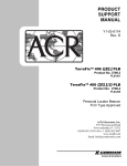
1
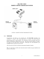
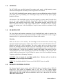
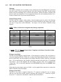
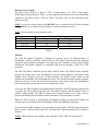
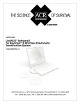
PRODUCT
SUPPORT
MANUAL
Y1-03-0138
Rev. H
RCL-100D™
Remote Control Searchlight
Master Controller
Point Pad
ACR Electronics, Inc.
5757 Ravenswood Road
Fort Lauderdale, Fl 33312
+1(954) 981-3333 · Fax +1 (954) 983-5087
www.acrelectronics.com
Email: [email protected]
A Chelton Group company
RCL-100D
TABLE OF CONTENTS
SECTION
1.0
2.0
3.0
4.0
5.0
6.0
7.0
8.0
9.0
10.0
FIGURES
Figure 1
Figure 2
Figure 3
Figure 4
Figure 5
Figure 6
Figure 7
Figure 8
Figure 9
TITLE
PAGE
Forward
General
Searchlight
Remote Control System
URP-102 Point Pad™
URC-102 Master Controller
RCL-100D Specifications
Bulb Replacement
RCL-100D Searchlight Components
Remote Control System Components
TITLE
1
2
2
2
3
11
15
17
17
18
PAGE
Remote Control Searchlight System
Point Pad™ Connection Block Diagram
URP-102 Point Pad™ Functions
URP-102 Point Pad™ Surface Mount Case
URP-102 Point Pad™ Flush Mount Case
URP-102 Point Pad™ Surface Mount Case w/Gasket and
Flush Mount Case with Gasket
URC-102 Master Controller Wiring Diagram
URC-102 Master Controller
Searchlight User Replaceable Parts List
i
1
4
5
6
7
8
11
12
14
Y1-03-0138 Rev. H
RCL-100D, 12/24V
REMOTE CONTROL SEARCHLIGHT SYSTEM
FIGURE 1: REMOTE CONTROL SEARCHLIGHT SYSTEM
1.0
FORWARD
Congratulations and thank you for purchasing the ACR RCL-100D Searchlight. The
combination of computer aided design, high quality raw materials, and quality-controlled
manufacturing produce a superior product. The Test Facility at ACR can reproduce some of the
harshest environmental conditions known to man. This assures that the products we produce
can stand up to the tough marine environment. With proper care and maintenance your
searchlight will be in service for years to come.
ACR is proud to be ISO 9001 certified, the International Standard for Quality.
Note: It is important to read this entire instruction manual carefully for proper installation and
operation of this product.
1
Y1-03-0138 Rev. H
2.0
GENERAL
The RCL-100D was specially designed for mariners who require a high intensity remote
controlled searchlight that can stand up to the tough marine environment.
The RCL-100D Searchlight System contains a narrow beam searchlight that produces 200,000
peak candle power by combining two 55W halogen lamps with our unique optical quality
parabolic reflectors.
All functions of the Searchlight can be electrically operated by remote control from the pilot
area of the vessel using the URP-102 Point Pad™, URC-102 Master Controller, and
interconnect cable supplied with the RCL-100D. Searchlights equipped with the URC-102
Master Controller now have ACR's unique XRCiZ feature. The XRCiZ feature routinely
operates all moving parts in the Searchlight to keep the motors and drive mechanism freely
running.
3.0
SEARCHLIGHT
The sleek design and modern construction of the Searchlight body makes it attractive for
recreational and commercial vessels. The Searchlight is totally enclosed and is made of rugged
aluminum alloy. It is gasketed and finished to be resistant to the weather.
Mounting
Make sure the area is clean and dry. The Searchlight can be mounted where desired, using
appropriate length 3/16" diameter, stainless steel fasteners. Four (4) nylon shoulder washers are
supplied with the RCL-100D Searchlight. The nylon washers prevent a galvanic reaction
between the mounting hardware and the base of the Searchlight. Be sure these washers have
been inserted in the base mounting holes and that the mounting base gasket is securely in place
before bolting down. Silicone grease should be applied to the bottom of the gasket to help in
waterproofing the unit. When mounting, be sure that the Searchlight is able to rotate 360°
without hitting any obstructions. For the drilling hole pattern, refer to the Searchlight Mounting
Template, supplied in the Mounting Templates.
CAUTION: Do not mount the searchlight upside down. Moisture will not be able to
drain from the inverted light head assembly.
NOTE: The Searchlight should be left uncovered if the XRCiZ feature is enabled.
4.0
REMOTE CONTROL SYSTEM
The Remote Control System consists of the URC-102 Master Controller and the URP-102
Point Pad™. This system is compatible with 12 VDC and 24 VDC systems without
modification. The Remote Control System may be used with 12 V or 24 V Searchlights, ONLY
THE LAMPS IN THE LIGHT HEAD ASSEMBLY MUST BE CHANGED TO MATCH
THE VOLTAGE RATING.
2
Y1-03-0138 Rev. H
5.0
URP-102 POINT PAD™
Case Options
The URP-102 Point Pad™ is supplied as a surface mount unit (see Figure4). A flush mount
option is provided (see Figure 5). To switch mounting options, unscrew the six (6) screws on
the unit’s back plate and remove the front cover. Fit the Point Pad™ with the flush mount
cover, replace the back plate, and screw the unit back together.
Mounting
Both the surface mount and flush mount options require access to the backside of the mounting
location. Make sure there are no obstructions behind the area where the switch is to be located
(e.g. bulkheads, wires, plumbing, or hardware). Check in advance that the coax cable from the
Master Controller can be routed to this location. Generally, the Point Pad™ should be mounted
in a protected area.
Install the surface mount Point Pad™ by drilling 3 holes in the dashboard location using the
Point Pad™ Surface Mount Template supplied in the Mounting Templates. Mount the Point
Pad™ to the dashboard using the gasket, washers, and nuts supplied. Use a sealant around the
bolt holes to protect from moisture intrusion.
When the flush mount option is selected, cut a rectangular hole in the dashboard location using
the Point Pad™ Flush Mount Template supplied in the Mounting Templates. Use the gasket,
washers, nuts, and the two U-Clamps provided to secure the Point Pad™. Use a sealant around
the cut out to protect from moisture intrusion.
Connecting to the Master Controller
The Point Pad™ communicates with the Master Controller via standard television type RG-59
coaxial cable. The connectors are standard "F" type television connectors. The connector on the
back of the Point Pad™ is located in the center of the panel for ease of installation. After the
coax cable has been routed and the “F” connectors attached to the coax cable, simply screw the
“F” connectors to the Master Controller and the Point Pad™. The cable and connectors are
available either through ACR Electronics, your local Radio Shack or other sources of electronic
hardware.
Additional Point Pads™ (up to three (3) Pads) may be used with one (1) Master Controller. A
standard "T" connector or RG-59 television type "splitter" is used for each additional Point
Padä (see Figure 2). Limit the total length of all coax cable used to 300 feet.
The URP-102 Point Pad™ is backwards compatible with all RCL-100/50 Searchlights and with
the URC-101 Master Controller.
NOTE: The URP-102 Point Pad™ is not recommended for use with the first generation URC100 Master Controllers.
3
Y1-03-0138 Rev. H
URC-102
Master
Controller Unit
URC-102
Master
Controller Unit
RG-59 Coaxial Cable
Fuse
RG-59 Coaxial Cable
Fuse
URP-102
Point Pad
Power
Source
“T” Conn.
or Splitter
Power
Source
RG-59 Coaxial Cable
URP-102
Point Pad
RG-59 Coaxial Cable
URP-102
Point Pad
Single Point Padä
Multiple Point Padsä
FIGURE 2: POINT PAD™ CONNECTION BLOCK DIAGRAM
4
Y1-03-0138 Rev. H
URP-102 Point Pad Functions
·
·
·
·
·
·
·
Press the ON/OFF button to turn the lights ON or OFF.
Press the SPEED button to toggle between High and Low rotation speeds.
Press the Right or Left Arrows to rotate the Searchlight in that direction.
Press the Up or Down Arrows to raise or lower the Searchlight-beam.
To activate the XRCiZ feature, press and hold the ON/OFF button for greater than 5 seconds.
The Green LED indicates XRCiZ feature is enabled.
To deactivate the XRCiZ feature, Press and hold the ON/OFF button for greater than 5
seconds. The Red LED indicates XRCiZ feature is disabled.
An LED blinking Red / Green indicates that the XRCiZ feature is now “exercising” the
Searchlight.
NOTE: XRCiZ Feature is only available when paired with a URC-102 Master Controller.
FIGURE 3: URP-102 POINT PAD™ FUNCTIONS
5
Y1-03-0138 Rev. H
6
FIGURE 4: URP-102 POINT PAD™ SURFACE MOUNT CASE
Y1-03-0138 Rev. H
7
FIGURE 5: URP-102 POINT PAD™ FLUSH MOUNT CASE
Y1-03-0138 Rev. H
8
FIGURE 6: URP-102 POINT PAD™
Surface Mount Case with gasket and Flush Mount Case with gasket
Y1-03-0138 Rev. H
6.0
URC-102 MASTER CONTROLLER
Mounting
The Master Controller can be mounted in any position near the Searchlight that is protected
from the weather. Check in advance that the coax cable from the Point Pad™ and the wiring
harness from the Searchlight can be routed to this location. Mount the Master controller with
the wires and coax facing down. Use an appropriate fastener for your mounting location. Use a
sealant in fastener holes to prevent moisture intrusion.
General Wiring Scheme
The RCL-100 has a unique wiring scheme. Special attention must be paid to the following
chart. The Master Controller is supplied with an in-line fuseholder on the Orange power lead.
Use only 15 amp fuses in this fuseholder. See Figure 9 for the Master Controller wiring
diagram.
NOTE: Failure to follow this arrangement may damage components.
Master
Controller Wire
Orange
Blue
Yellow
Green
Red
White
Black
Brown
Searchlight
Cable Wire
Power Source Lead
Function
+12 VDC or +24 VDC**
Ground
Power
Ground
Lamp Power
Lamp Ground
Up
Down
Right
Left
Yellow
Green
Red
White
Black
Brown
Table 1
** NOTE: This wire MUST be fused with a 15 amp fuse in the Master Controller's in-line
fuseholder.
Wiring to Searchlight
The RCL-100 Searchlight is supplied with a 15 foot integral wire harness. This wire harness is
cut to this length specifically to allow for a voltage drop. Shortening the harness will decrease
the life of the bulbs. Any extra length of wire harness should be loosely coiled in a convenient
place. For best performance, the controller should be attached to the end of the 15' Searchlight
wire harness. If you must lengthen the wire harness, use heavy duty wire to minimize the
voltage drop. This is especially important for the YELLOW lamp power and GREEN lamp
ground wires.
Following the wiring scheme shown in Table 1 use the supplied butt connectors to connect the
Master Controller to the Searchlight.
Wiring to Point Pad™
The RG-59 Coax cable is supplied without the “F” connectors attached for ease of routing.
After the coax has been routed, strip the insulation and crimp the “F” connectors in place.
Screw the “F” connectors to the Master Controller and the Point Pad™.
9
Y1-03-0138 Rev. H
Wiring to Power Supply
The power source must be a fused 12 VDC, 10-amp supply or 24 VDC, 5-amp supply.
Following the wiring scheme in Table 1, use the supplied butt connectors to connect the Master
controller to the Power Source. Refer to Table 2 for proper wire size for connection of the
input power lines.
NOTE: As per the wiring scheme, the ORANGE wire is connected to the Positive terminal
and the BLUE wire is connected to the Negative terminal of the power source.
NOTE: Observe polarities when attaching wires!
Wire Size
#8 AWG
#10 AWG
#12 AWG
Maximum Cable Length
12v System
24v System
25 ft.
100 ft.
15 ft.
60 ft.
10 ft.
40 ft.
Table 2
Function
The URC-102 Master Controller is designed to perform up to six different duties on
searchlights, winches, and other electrical devices. The Master Controller provides optimum
voltage to ensure brightest performance and long lamp life, regardless of boat system voltage
fluctuations. The Master Controller is compatible with devices requiring 12 VDC or 24 VDC
operation.
The URC-102 Master Controller has the unique XRCiZ feature. The XRCiZ feature routinely
operates all moving parts in the Searchlight to keep the motors and drive mechanism freely
running. Once activated, and every 30 days thereafter, the XRCiZ feature wakes up and
operates the Searchlight. The Searchlight will rotate 360° in both directions and the parabolic
reflectors will move to the full up and down positions. This feature keeps the Searchlight in
peak working order when not in service for long periods of time.
To activate the XRCiZ feature, press and hold the Point Pad™ ON/OFF button for greater than
5 seconds. The Green LED on the URC-102 Point Pad™ indicates that the XRCiZ feature is
enabled. While enabled, The XRCiZ feature can be started outside of its 30-day cycle by
pressing and holding the Speed button on the Point Pad™ for greater than 5 seconds.
While the XRCiZ feature is operating the Searchlight, pressing any Point Pad™ button will
stop the current cycle and leave the Searchlight to follow any additional commands.
To deactivate the XRCiZ feature, press and hold the Point Pad™ ON/OFF button for greater
than 5 seconds. The Red LED on the URC-102 Point Pad™ indicates that the XRCiZ feature is
disabled.
NOTE: LED feedback is not available when using RCL-100 or URC-101 Point Pads™.
10
Y1-03-0138 Rev. H
NOTE: The Searchlight should not be covered while the XRCiZ feature is enabled.
The URC-102 Master Controller provides optimum voltage to ensure the brightest Searchlight
performance and long bulb life. Also to extend lamp life, the Master Controller has a timed
lamp power up feature. The Searchlight lamps reach full intensity within 2 seconds.
The URC-102 Master Controller has a Searchlight motor timeout feature. If a Point Pad™
rotation switch (right or left) is continuously engaged for more than 50 seconds, the Master
Controller will interrupt the operation until the Point Pad™ switch is disengaged. This feature
will save the Searchlight motor from burnout due to accidental activation. The elevation motor
has similar features which will timeout in approximately 20 seconds.
FIGURE 7: URC-102 MASTER CONTROLLER WIRING DIAGRAM
11
Y1-03-0138 Rev. H
.34
[8.6]
2.80
[71.1]
4.50
[114.3]
3.63
[92.2]
3.64
[92.5]
1.15
[29.2]
Figure 8: URC-102 MASTER CONTROLLER
12
Y1-03-0138 Rev. H
7.0
RCL-100D SPECIFICATIONS (with URC-102 Controller)
Specifications
12V UNIT
24V UNIT
Mirror Diameter
4" x 2-3/4"
Same
Rated Voltage (Volt)
12 to 16 VDC
24 to 31 VDC
Rated Current (A)
10
5
Applicable Lamp
55W Halogen
55W Halogen
Lamp x 2
Lamp x 2
(Base-G6.35)
(Base-G6.35)
JCD12V-55WDX
JCD24V-55WDX
200,000
160,000
Horizontal
7°
Same
Vertical
5°
Same
Up
9°
Same
Down
17°
Same
Turning Angle (degrees)
360°
Same
Elevation Speed
4° per second
Same
Fast
28° per second
Same
Slow
15° per second
Same
Weight
7.15 pounds
Same
Interconnect Cable
15 feet
Same
Peak Beam Candle Power (candela)
Beam Spread (degrees)
Elevation Angle (degrees)
Turning Speed
Note: All specifications are nominal values
13
Y1-03-0138 Rev. H
ACR/RCL-100D
ITEM NO.
1
2
3A
3B
3C
4
5
6
7
8A
or
8B
9
10
11
DESCRIPTION
Front Glass
Front Frame
Window Weather Strip
Screw M4x18
Washer M408
Gasket of front frame
10 cm reflector
Protection Cover
O-Ring #594
55W quartz halogen
Bulb (12V)
55W quartz halogen
Bulb (24V)
Shoulder Washer
Base Housing
Head Housing
QTY
PART NUMBER
1
1
1
2
2
1
2
1
1
2
HRMK 1300
HRMK 1101
HRMK 1201
HRMK 1600
HRMK 9301
HRMK 1200
HRMK 1301
HRMK 2102
HRMK 2202
A1-14-0080-1
2
A1-14-0080-2
4
1
1
A1-05-0660-24
HRMK2103
HRMK2101
FIGURE 9: SEARCHLIGHT USER REPLACEABLE PARTS
14
Y1-03-0138 Rev. H
8.0
BULB REPLACEMENT
Two 55W, quartz-halogen bulbs are provided with your RCL-100D. If they should need
replacement, they must be ordered through ACR Electronics, by P/N A1-14-0080-1 (12V units)
or A1-14-0080-2 (24V units).
To replace the lamps:
1.
Disconnect unit from power source and allow bulbs to cool.
2.
Remove two screws holding the front flange and glass in place.
3.
To remove the old lamp bulbs, grasp base of the lamp and pull straight out. DO NOT
TOUCH GLASS PARABOLIC REFLECTORS WITH FINGERS OR TOOLS!
4.
Install the new lamp bulb using a soft clean cloth to avoid touching the bulb with your
fingers. Insert the lamp bulb pins into socket and press firmly in place.
NOTE: If the Lamp Bulb or Reflectors are accidentally touched, carefully clean with
a soft rag and alcohol before continuing.
9.0
5.
Replace the front flange and glass and install the two retaining screws. Be sure the
neoprene gasket is securely in place.
6.
Reconnect the unit to the power source.
RCL-100D SEARCHLIGHT COMPONENTS
PRODUCT NO. 1930.3 - RCL-100D 12 V Searchlight Installation Kit includes:
Description
Searchlight, RCL-100D, 12 V
Kit, Nylon Washers (4)
Connector, “F”
Cable, Coaxial
Master Controller, URC-102
Connector, "In-Line"
Point Pad™, URP-102 with
Surface Mount Case
Case, Flush Mount
Gasket, Surface Mount
Gasket, Flush Mount
U Clamp
Nuts, Nylon-lock
Washers
Warranty Card
Product Support Manual
Mounting Templates
Troubleshooting and
Maintenance Guide Instructions
Quantity
1
1
2
15'
1
8
ACR Part Number
A3-06-1106-3
A3-06-1940
A1-03-0220
A2-07-0002-6
A3-06-2231
A1-03-0222
1
1
1
1
2
2
2
1
1
1
A3-06-2230
A1-18-1875-2
A1-25-0140-1
A1-25-0140-2
A1-17-1366
A1-05-0776
A1-05-0777
A1-20-1019
Y1-03-0138
Y1-03-0138-1
1
Y1-03-0137
15
Y1-03-0138 Rev. H
PRODUCT NO. 1931.3 - RCL-100D 24 V Searchlight Installation Kit includes:
Description
Searchlight, RCL-100D, 24 V
Kit, Nylon Washers (4)
Connector, “F”
Cable, Coaxial
Master Controller, URC-102
Connector, "In-Line"
Point Pad™, URP-102 with
Surface Mount Case
Case, Flush Mount
Gasket, Surface Mount
Gasket, Flush Mount
U Clamp
Nuts, Nylon-lock
Washers
Warranty Card
Product Support Manual
Mounting Templates
Troubleshooting and
Maintenance Guide Instructions
Quantity
1
1
2
15'
1
8
1
1
1
1
2
2
2
1
1
1
1
ACR Part Number
A3-06-1106-4
A3-06-1940
A1-03-0220
A2-07-0002-6
A3-06-2231
A1-03-0222
A3-06-2230
A1-18-1875-2
A1-25-0140-1
A1-25-0140-2
A1-17-1366
A1-05-0776
A1-05-0777
A1-20-1019
Y1-03-0138
Y1-03-0138-1
Y1-06-0137
10.0 REMOTE CONTROL SYSTEM COMPONENTS
PRODUCT NO. 1927.3 - URC-102 Master Controller Installation Kit includes:
Description
Quantity
Master Controller, URC-102
1
Connector, "In-Line"
8
Instruction Sheet, Master Controller
1
ACR Part Number
A3-06-2231
A1-03-0222
Y1-06-0178
PRODUCT NO. 1928.3 - URP-102 Point Pad™ Installation Kit includes:
Description
Point Pad™, URP-102 with
Surface Mount Case
Case, Flush Mount
Gasket, Surface Mount
Gasket, Flush Mount
U Clamp
Nuts, Nylon-lock
Washers
Quantity
1
1
1
1
2
2
2
ACR Part Number
A3-06-2230
A1-18-1875-2
A1-25-0140-1
A1-25-0140-2
A1-17-1366
A1-05-0776
A1-05-0777
16
Y1-03-0138 Rev. H
Adapter Plate, Flush mount
Adapter Plate, Surface mount
Instruction Sheet, Point Pad™
Mounting Templates
1
1
1
1
A1-18-1871
A1-18-1892
Y1-06-0179
Y1-03-0138-1
PRODUCT NO. 1929.1 - Wiring Kit RCL-50 / 100 Series Searchlights Includes:
Description
Connector, “F”
Cable, Coaxial
Quantity
2
15'
ACR Part Number
A1-03-0220
A2-07-0002-6
PRODUCT NO. 9282.3 – URP-102 Point Pad™ Secondary Station Installation Kit includes:
Description
Point Pad™, URP-102 with
Surface Mount Case
Case, Flush Mount
Gasket, Surface Mount
Gasket, Flush Mount
U Clamp
Nuts, Nylon-lock
Washers
Adapter Plate, Flush mount
Adapter Plate, Surface mount
Splitter, 2-Way Signal
Screw, #6
Cable, Coaxial
Connector, "F"
Instruction Sheet, Point Pad™
Mounting Templates
Quantity
1
1
1
1
2
2
2
1
1
1
2
15'
4
1
1
17
ACR Part Number
A3-06-2230
A1-18-1875-2
A1-25-0140-1
A1-25-0140-2
A1-17-1366
A1-05-0776
A1-05-0777
A1-18-1871
A1-18-1892
A1-03-0235
A1-05-0614
A2-07-0002-6
A1-03-0220
Y1-06-0179
Y1-03-0138-1
Y1-03-0138 Rev. H
PRODUCT NO. 9283.3 – Remote Control Installation Kit Includes:
Description
Quantity
Master Controller, URC-102
1
Connector, "In-Line"
8
Point Pad™, URP-102 with
Surface Mount Case
1
Case, Flush Mount
1
Gasket, Surface Mount
1
Gasket, Flush Mount
1
U Clamp
2
Nuts, Nylon-lock
2
Washers
2
Adapter Plate, Flush mount
1
Adapter Plate, Surface mount
1
Cable, Coaxial
15'
Connector, "F"
2
Instruction Sheet, Master Controller
1
Instruction Sheet, Point Pad™
1
Mounting Templates
1
18
ACR Part Number
A3-06-2231
A1-03-0222
A3-06-2230
A1-18-1875-2
A1-25-0140-1
A1-25-0140-2
A1-17-1366
A1-05-0776
A1-05-0777
A1-18-1871
A1-18-1892
A2-07-0002-6
A1-03-0220
Y1-06-0178
Y1-06-0179
Y1-03-0138-1
Y1-03-0138 Rev. H