1
Smart Relay:
SREL, SREL.ZK, SREL.AKV
State of: June 2006
Smart Relay: SREL, SREL.ZK, SREL.ADV
Content
1.0
Important Information _________________________________4
2.0
Product Description ___________________________________4
3.0
Before Ordering ______________________________________5
4.0
3.1
Determine Which Version of the Smart Relay you need_________ 5
3.2
Determine Which Accessories you Need _____________________ 5
3.3
Dimension and Procure Power Supplies _____________________ 5
3.4
Determine the Installation Position__________________________ 6
3.5
Additional Information: ___________________________________ 6
Before Installation ____________________________________6
4.1
Installation of the Backup Battery___________________________ 7
5.0
Installation __________________________________________8
6.0
Connection Assignments ______________________________9
6.1
SREL and SREL.ZK ______________________________________ 9
6.2
SREL.ADV _____________________________________________ 10
6.3
Description of the SREL, SREL.ZK and
SREL.ADV Connections __________________________________ 10
7.0
Programming and Configuration _______________________11
7.1
Access control _________________________________________ 12
7.2
Time zone control _______________________________________ 12
7.3
Overlay________________________________________________ 12
7.4
Flip Flop _______________________________________________ 12
7.5
Repeater_______________________________________________ 12
7.6
Time switching _________________________________________ 12
7.7
OMRON _______________________________________________ 13
7.7.1 The Smart Relay in OMRON Mode _________________________ 14
7.7.2 No acoustic programmer acknowledge _____________________ 15
7.7.3 External beeper/ External LED ____________________________ 15
Smart Relay: SREL, SREL.ZK, SREL.ADV
Content
7.7.4 Internal/ external antenna ________________________________ 15
7.7.5 Number of expansion modules ____________________________ 15
7.7.6 Pulse length ___________________________________________ 15
7.7.7 Interface _______________________________________________ 16
7.7.8 Restricted range ________________________________________ 16
7.7.9 External Beeper/ External LED ____________________________ 16
7.7.10 Log unauthorized accesses_______________________________ 17
8.0
The Smart Relay as a serial Interface____________________18
8.1
Functional Description___________________________________ 18
8.2
Wiegand Interface (32 bit and 26 bit) _______________________ 18
8.3
Kaba Benzing, Siemens, Gantner Legic, Primion,
Isgus Interface _________________________________________ 19
9.0
Maintenance ________________________________________19
9.1
Battery Warning and Battery Replacement if you are using
the SREL.BAT Battery ___________________________________ 19
9.2
Backup Battery _________________________________________ 20
10.0 Data sheet __________________________________________21
Smart Relay: SREL, SREL.ZK, SREL.ADV
Page 4
1.0
Important Information
Safety remark:
Caution! – Incorrect handling of the batteries and storage batteries used in this product can result in the risk of fire or burns. Do not charge, open or burn these batteries
or heat them to more than 100 °C (212 °F).
Installation of a SimonsVoss Smart Relay requires knowledge in the areas of door
mechanics, door certifications, installation of electronics and the use of the SimonsVoss software. For this reason, only trained and authorised personnel should install
the unit.
SimonsVoss Technologies AG will not accept any liability for damages caused by
incorrect installation.
Incorrectly installed Smart Relays may block the access through a door. SimonsVoss
AG is not liable for the consequences of incorrect installation, such as blocked access
to injured or endangered persons, property damage or other damages.
If you will be storing the Smart Relay for more than one week, remove the backup
battery.
The Smart Relay must be installed in compliance with ESD (electrostatic discharge)
guidelines. In particular, contact with the printed circuit boards and the switching
circuits integrated on them must be avoided.
2.0
Product Description
The SimonsVoss Smart Relay is an electronic switch that you can switch with a
SimonsVoss transponder. You can use the SimonsVoss software to configure the
authorisation for transponders that are permitted to operate the Smart Relay. As a
result, the Smart Relay offers the full function of an access control reader.
Smart Relay: SREL, SREL.ZK, SREL.ADV
Page 5
3.0
Before Ordering
3.1
Determine Which Version of the Smart Relay you need
1. Smart Relay basic version: ordering code SREL
This relay allows simple yes/no authorisation for up to 8184 different transponders.
2. Smart Relay Plus version with access logging and time zones: ordering code
SREL.ZK.
Like the basic version, but with the capability of separately switching on access logging for the last 1024 accesses (for firmware version 4.0.01.15 and
later), with date and time, or day-time zones for up to five groups of people,
and automatic locking and unlocking.
3. Smart Relay Advanced version, ordering code SREL.ADV
Like the Plus version, but with the following additional functions:
- Connection for external modules using a three-wire bus
- Connection of an extended antenna
- Connections for serial interfaces to external time recording terminals or
access control readers
- Connection for external LED or buzzer
3.2
Determine Which Accessories you need
Extended antenna for unfavourable reception conditions ordering code: SREL.AV
Battery only for SREL, SREL.ZK and SREL.ADV in case you will be operating these
products without an additional supply voltage: ordering code SREL.BAT
3.3
Dimension and Procure Power Supplies
These power supplies are necessary for all Smart Relays that will not be battery operated. The power supply should have an output of no more than 15 watts and should
be capable of delivering voltage of 12 VAC or 5 to 24 VDC when the current is
100 mA.
Attention! Do not user any switched-mode power supplies near the Smart Relays.
The customer must provide all power supplies; they are not available from
SimonsVoss.
Smart Relay: SREL, SREL.ZK, SREL.ADV
Page 6
3.4
Determine the Installation Position
The range from the transponder to the Smart Relay (reader range) is a maximum of
1.5 m (5 feet), but can be dampened by a metal environment (particularly by strong
magnetic fields or aluminium).
Ideally, you should conduct a range test with an authorised transponder and a
battery-operated Smart Relay.
3.5
4.0
Additional Information:
-
All cables for connecting to the Smart Relay should be type IY(ST)Y ....x0.6
(Twisted-Pair shielded cable). The maximum cable length should not exceed
100 m (approximately 330 feet). At the same time, you must take into account
the power losses when you dimension the supply voltage.
-
You must take into consideration the technical specifications for the inputs and
outputs (see Technical Data)
-
You must lay and connect all cables according to VDE standards.
Before Installation
Unpack the Smart Relay and check for any damages.
Connect the Smart Relay to a supply voltage or battery.
If you are operating the Smart Relay with a power supply, insert the backup
battery included in the delivery into the holder provided for it (see Installation
of the Backup Battery).
Verify the function of the Smart Relay with a transponder in the condition as
received from the factory.
If you are installing the Smart Relay in a flush socket device, remove the
housing.
If you are installing the Smart Relay on the wall, you can use the bottom plate
as a template for the bore holes (6 mm).
Smart Relay: SREL, SREL.ZK, SREL.ADV
Page 7
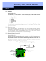
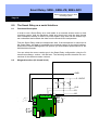
Installation of the Backup battery
Backup
Batterie
das the
Smart
Relais
Insert the
battery nur
only einsetzen,
if you will bewenn
operating
Smart
Relaymit
with
Netzteil
bei Betrieb
mit ifSREL.BAT
diese
the
powerbetrieben
supply. Dowird,
not insert
this battery
you will be operating
with nicht
the SREL.BAT!
Batterie
einsetzen!
SREL
SREL
and
SREL.ZK
und SREL.ZK
+/~
-/~
C
A
B
+V
F3
F2
F1
SREL.ADV
BN
WH
GN
GY
YL
+
Backup
Batterie
Insert
the backup
battery
in the delivery)
(im(included
Lieferumfang
enthalten)
in the holder
in die Halterung
einführen
POSITIVE POLE UP
PLUSPOL NACH OBEN
SREL
SREL
and
SREL.ZK
und SREL.ZK
SREL.ADV
+/~
-/~
C
A
B
+V
F3
F2
F1
4.1
+
BN
WH
GN
GY
YL
+
Smart Relay: SREL, SREL.ZK, SREL.ADV
Page 8
5.0
Installation
Switch off the supply voltage (if necessary, pull out the plug or disconnect the
battery).
Connect all cables to the terminals provided on the Smart Relay (see Connection Assignments on the following page)
If you are connecting a direct current power supply, make sure that you
get the polarity right.
You can attain the largest reader range if you align the Smart Relay antennas
so that they are parallel to that on the transponder during the installation.
Switch on the supply voltage (if necessary, insert the plug or connect the
battery).
Verify the function of the Smart Relay with a transponder in the condition as
received from the factory.
Program the Smart Relay with the SimonsVoss software (we recommend
software version LDB.EXE 1.40 or later).
Use a transponder that is now authorised in order to test the functioning of the
Smart Relay again.
Smart Relay: SREL, SREL.ZK, SREL.ADV
Page 9
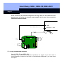
6.0
Connection Assignments
6.1
SREL and SREL.ZK
Power
Netzteil
{ +- // ~~
Battery
Batterie SREL.BAT
Relais
Rel
{
Antenna
NC
COM
NO
1 RS 485-COM
2 RS 485-A
3 RS 485-B
4 + Vaux (3...5 V)
5 LED / Buzzer / Input 1 / CLS
6 Seriell 1 / Input 2
7 Seriell 2
Externe Einund
external
inputs
Ausgänge
and
outputs
+/~
Power Netzteil
supply {
-/~
Battery SREL.BAT
Batterie
Relay
Relais
{
NC
COM
NO
Brown
White
Green
Grey
Yellow
}
External antenna
Externe
Antenne
SREL.AV
SREL.AV
Antenna
Smart Relay: SREL, SREL.ZK, SREL.ADV
Page 10
6.2
SREL.ADV
6.3
Description of the SREL, SREL.ZK and SREL.ADV Connection
Name
Power supply
Symbol
Power supply
-/~
+/~
Battery
NC relay
Description
If connecting a direct current (5 to 24 VDC) source, use the
positive pole, otherwise use one of the two alternating current
connections (12 VAC)
If connecting a direct current (5 to 24 VDC) source, use the
negative pole, otherwise use the second alternating current
connection (12 VAC)
Plug connection for a battery (when operating without a power
supply) Battery ordering code, incl. connector: SREL.BAT
Normally closed contact for the change-over relay. When not
acted on, this contact is closed to the COM relay
COM relay
Common contact on the change-over relay. This contact is either wired to the NC relay (normally closed contact) or to the
NO relay (normally open contact)
NO relay
Normally open contact on the change-over relay. When acted
on, this contact is closed to the COM relay
Connection for the coloured cables of an extended antenna
(ordering code SREL.AV)
External antenna
Brown
White
Green
Grey
Yellow
BN
WH
GN
GY
YL
RS-485COM
RS-485A
RS-485B
C
A
B
Bus connection for external modules
+ Vaux
+V
LED/ Buzzer/
Input 1/ CLS
Serial 1/ input 2
Serial 2
F3
Typically 3.0 - 5.0V +/- 0.5V for external LED’s or buzzer,
max. 10mA
Multifunction connection
F2
F1
Multifunction connection
Multifunction connection
Smart Relay: SREL, SREL.ZK, SREL.ADV
Page 11
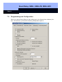
7.0
Programming and Configuration
When you choose Smart Relay as the locking type in the SimonsVoss software (Version 1.40 and later), you have the following configuration option’s:
Smart Relay: SREL, SREL.ZK, SREL.ADV
Page 12
7.1
Access control
Only possible for SREL.ZK and SREL.ADV
The last 1024 transponder activation’s are saved with the date and time.
7.2
Time zone control
Only possible for SREL.ZK and SREL.ADV
You can load a time zone plan and the transponders are then approved or blocked,
according to their time zone group.
7.3
Overlay
Replacement transponders can overwrite the transponders that they replace. After
the first operation with a replacement transponder, the system blocks the original
transponder.
7.4
Flip Flop
Pulse mode (default setting) is switched off, and the pulse width does not matter any
more. When flip flop mode is switched on, the Smart Relay changes its state from ON
to OFF or back again, each time the transponder is activated. We recommend this
mode for switching lights or machines, etc.
With an installation of this kind, it may be necessary to make sure that the
power supplies and door openers are suitable for continuous current operation.
7.5
Repeater
The Smart Relay receives a transponder signal and then sends it again, amplified.
You can use the Smart Relay in this function in order to link a way through larger
radio paths. The distance to another Smart Relay can be up to 2.0 m (6.5 ft).
7.6
Time switching
Only for SREL.ZK and SREL.ADV
If time switching is activated, you must load a time zone plan, which allows a general
release of the Smart Relay during the marked times (in Group 5). This means that a
door can be freely accessible during the day but only opened by transponder at night.
With an installation of this kind, you must make sure that the power supplies
and door openers are suitable for continuous current operation.
If you select time switching, the "Time-controlled relay switching" field has the following option’s (you may select more than one):
Smart Relay: SREL, SREL.ZK, SREL.ADV
Page 13
1. Manual locking:
The door is not locked automatically according to the selected time of day, but
instead only after an authorised transponder is operated after this time.
2. Automatic locking (default setting):
The door is locked at exactly the time stored in the time zone plan.
3. Manual unlocking (default setting):
The door is not unlocked automatically according to the selected time of day,
but instead only after an authorised transponder is operated after this time.
4. Automatic unlocking:
Normally, the door is not opened at the selected time of day, but instead only
after operation with the first transponder. If it is required that the door always
open automatically at the selected time of time, then select this option.
5. Transponder active:
- Always:
Normally, a transponder cannot be used during the released periods. If it is
necessary, however, to be able to lock the door during this time (for example,
if everyone leaves the building), then select this option.
- Only when locked:
In this operating mode, the transponder has no effect during the released
time.
7.7
OMRON
Only for SREL.ADV
Many access control and time recording systems have serial interfaces for connection
to card readers. It is also possible to connect a Smart Relay over these interfaces.
This means that you can also use the SimonsVoss transponder in systems from other
companies.
If you would like the Smart Relay to transmit the transponder data to such an external
system, and for the Smart Relay to send a remote opening command to a cylinder
when released by this external system, then select this option, both on the Smart
Relay and on the cylinder.
Select the type of external system under "Interface". The following types are available:
Smart Relay: SREL, SREL.ZK, SREL.ADV
Page 14
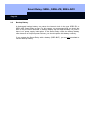
7.7.1
The Smart Relay in OMRON Mode
Authorized?
Access control system
Externes
Zutrittskontrolloder
External access
control or
Zeiterfassungssystem
time recording system
GND
Release relay
Freischalt Relais
+ 5..12VDC
1K
1K
1K
Pull
Up up
Widerstände
Pull
resistors
CLS
Clock / D1
Data / D0
Power
Netzteil
{ +- // ~~
F3 F2 F1
Battery
SREL.BAT
Batterie
SREL.BAT
Relais
Relay
{
NC
COM
NO
Brown
White
Green
Grey
Yellow
}
ExternalAntenne
antenna
Externe
SREL.AV
SREL.AV
Smart Relay: SREL, SREL.ZK, SREL.ADV
Page 15
7.7.2
No acoustic programmer acknowledge
Only SREL.ADV
Mark this field if you want no programmer acknowledge to be given via a connected
buzzer/beeper when the Smart Relay is programmed.
7.7.3
External beeper/ External LED
Only SREL.ADV
This is where you specify which external unit is connected. In Flip Flop mode, the
Smart Relay generates a continuous signal when switched if there is an external LED
connected; if a beeper is connected, it briefly acknowledges each change of state
with a sound signal.
7.7.4
Internal/ external antenna
Only SREL.ADV
- Autodetection:
If an external antenna is connected, only this antenna is used. The Smart
Relay then switches the internal antenna off. If no external antenna is connected (default case), the Smart Relay works with the internal antenna.
-
7.7.5
Both active:
The Smart Relay can assess entries from transponders at both antennas.
Number of expansion modules
Only for SREL.ADV
This is where you indicate the number of external modules that are connected to the
Smart Relay. These modules are connected to terminals RS-485 COM, RS-485
A and RS-485 B. For more information, refer to the documentation for the separate
modules.
7.7.6
Pulse length
This is where you specify the value, in seconds, for the pulse width of the switching
pulse. The value has a range from 0.1 to 25.5 seconds. For example, if you enter
3 seconds here, then a door opener will be released for 3 seconds before it is then
blocked again.
Smart Relay: SREL, SREL.ZK, SREL.ADV
Page 16
7.7.7
Interface
Only for SREL.ADV
For operation as a serial interface, you can select the type of card reader here that
the Smart Relay should simulate. You have the following option’s:
Wiegand 32 bit
Wiegand 26 bit
Primion
Siemens
Kaba Benzing
Gantner Legic
Isgus
You will find the corresponding cabling information in the chapter "The Smart Relay
as a Serial Interface".
7.7.8
Restricted range
If you select this option, the reader range from the transponder Æ Smart Relay is
restricted from approximately 1.5 m (4.9 ft) down to 0.4 m (1.3 ft). For example, you
can use this option if there are several Smart Relays close to one another and individual transponders are authorised for several Smart Relays.
7.7.9
External Beeper/ External LED
Only for SREL.ADV
Normally, the Smart Relay is configured for connection to an LED. If you want to connect a beeper or buzzer as the external signaller, mark this option. In this way, the
beeper/buzzer can be used for an acoustic acknowledgement, instead of the LED.
Should the connected component need less than 10 m maximum current at
3 VDC, the connecting plan can look as follows:
Evtl. Widerstand
zur restricting power
Possibly
resistor for
Leistungsbegrenzung.
The V+ output supplies a max. 10 mA at 3 VDC
Der Ausgang V+ liefert
max. 10 mA bei 3VDC
Entweder Buzzer oder LED
Netzteil
{ +- // ~~
Batterie SREL.BAT
Relais
{
NC
COM
NO
V+ F3
Brown
White
Green
Grey
Yellow
}
Externe Antenne
SREL.AV
Smart Relay: SREL, SREL.ZK, SREL.ADV
Page 17
If the current for the external component is larger than 10 mA, then this component must be fed by an external power supply. In this case, the connection
should be made as follows:
Ext. Netzteil
External
power
supply
GND
Evtl. W iderstand zur
Possibly resistor for restricting power
Leistungsbegrenzung.
The F3 Der
output
is max. 50 mA.
Ausgang F3 verträgt
Maximal + 24V
max. 50 mA
Entweder
Buzzer
Either buzzer
oroder
LEDLED
Netzteil
Power
{
+/~
-/~
F3
BatterieSREL.BAT
SREL.BAT
Battery
Relais
Relay
{
Brown
White
Green
Grey
Yellow
}
Externe
External Antenne
antenna
SREL.AV
SREL.AV
NC
COM
NO
7.7.10 Log unauthorised accesses
Only for SREL.ZK and SREL.ADV
Normally, only authorised transponder operations are logged. If you also want to
record attempts to open the door with an unauthorised transponder, you must select
this option.
Smart Relay: SREL, SREL.ZK, SREL.ADV
External access control or time
recording system
Page 18
8.0
The Smart Relay as a serial Interface
8.1
Functional Description
In order to use a Smart Relay as a card reader in an external access control or time
recording system, both the hardware (cable and signal level) and the data formats
must correspond exactly to those of the card reader. Only then can the external system understand and evaluate the data from the SimonsVoss transponders.
First the Smart Relay reads the transponder data. If the transponder is authorised in
the Smart Relay, this data is forwarded to the external system via the serial interface.
SimonsVoss Product Management will provide you with detailed specifications for the
individual data formats.
You can select the correct reader type in the Smart Relay configuration using the SimonsVoss software, version 1.40 and later. The following sections describe the connections for the different reader versions.
8.2
Wiegand Interface (32 bit and 26 bit)
External
access control oroder
Externes
Zutrittskontrolltime recording system
Zeiterfassungssystem
GND
+ 5..12VDC
1K
1K
1K
Pull-up
resistors
Pull
Up Widerstände
CLS
D1
D0
Power
Netzteil
{ +- // ~~
F2 F1
Battery
BatterieSREL.BAT
SREL.BAT
Relay
Relais
{
NC
COM
NO
Brown
White
Green
Grey
Yellow
}
Externe
External Antenne
antenna
SREL.AV
SREL.AV
Smart Relay: SREL, SREL.ZK, SREL.ADV
Page 19
8.3
Kaba Benzing, Siemens, Gantner Legic, Primion, Isgus Interface
Externes
ZutrittskontrollExternal access
control oroder
time
recording system
Zeiterfassungssystem
GND
+ 5..12VDC
1K
1K
1K
Pull-up
resistors
Pull
Up Widerstände
CLS
Clock
Data
+/~
Power supply
Netzteil {
F2 F1
-/~
Batterie
SREL.BAT
Battery
SREL.BAT
Relay
Relais
{
Brown
White
Green
Grey
Yellow
}
Externe
ExternalAntenne
antenna
SREL.AV
SREL.AV
NC
COM
NO
9.0
Maintenance
9.1
Battery Warning and Battery Replacement if you are using the
SREL.BAT battery
In case the battery capacity is no longer sufficient, a Smart Relay can issue a battery
warning as follows:
SREL, SREL.ZK, SREL.ADV
Internal LED blinks 8 times each time you operate the transponder and before
the relay is switched.
If you are operating with a battery, you should make sure that this LED can be
seen from the outside.
Only SREL.ADV
External LED blinks 8 times or external buzzer beeps 8 times, each time you
operate the transponder.
Approximately 100 operations are possible after the battery warning, so you
should replace the battery as soon as possible.
Smart Relay: SREL, SREL.ZK, SREL.ADV
Page 20
9.2
Backup Battery
A discharged backup battery can cause the internal clock in the type SREL.ZK or
SREL.ADV Smart Relay to stop. For this reason, we recommend that you check the
time of day at routine intervals. A backup battery will last approximately 10 years if
there is no power supply interruption. If the Smart Relay needs the backup battery
often because of frequent power failures, you should replace this battery routinely.
If you operate the Smart Relay with a battery (SREL.BAT), you are not permitted to
use the backup battery.
Smart Relay: SREL, SREL.ZK, SREL.ADV
Page 21
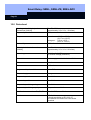
10.0 Data sheet
Housing made of black plastic:
Dimensions [LxWxH]
Degree of protection
72 x 57 x 25.5 mm
(approximately 2.8 x 2.2 x 1.0 inches)
IP 20, not tested for outside use
Temperature
Air humidity
Operation at: -22°C to +55°C
(-31°F to +131°F)
Storage at: 0°C to +40°C
(32°F to +104°F)
<95% without moisture condensation
Printed circuit board dimensions
[LxWxH]
50 x 50 x 14 mm
(approximately 2.0 x 2.0 x 0.6 inches)
Line voltage
12 VAC or 5-24 VDC
(no reverse voltage protection)
Power limit
Power supply must be limited to 15 VA
Quiescent current
< 5 mA
Max. current
< 100 mA
Programmable pulse width
0.1 to 25.5 seconds
Output relay type
Change-over
Output relay continuous current
Max. 1.0 A
Output relay switch on current
Max. 2.0 A
Output relay switching voltage
Max. 24 V
Output relay switching capacity
106 operations at 30 VA
Multifunction connections: F1, F2, F3
Max. 24 VDC, max. 50mA
Vibrations
15G for 11 ms,
6 shocks according to IEC 68-2-27
Not released for continuous used under
vibrations