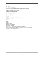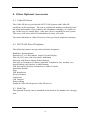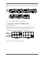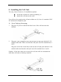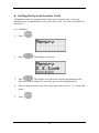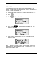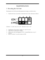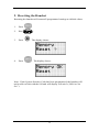
1
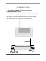
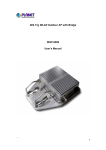
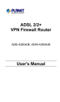
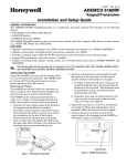
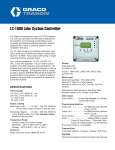
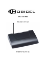
DCTS-900
Digital Cell Unit
USER’S MANUAL
MobiCel Systems, Inc. has made every effort to ensure the technical accuracy
of this manual. Features and technical data are subject to change without
notice.
Copyrightã 1997, MobiCel Systems, Inc. All Rights Reserved.
WARNING
MobiCel Systems, Inc. doesn’t represent this unit to be waterproof. To
reduce the risk of fire, electrical shock, or damage to the unit, do not expose
this unit to rain or moisture.
IMPORTANT SAFETY INSTRUCTIONS
When using your telephone equipment, basic safety precautions should
always be followed to reduce the risk of fire, electrical shock, and injury to
persons, including the following:
1.
2.
3.
Read and understand all instructions.
Follow all warnings and instructions marked on the product.
Unplug this product from the wall outlet before cleaning. Do not use
liquid cleaners or aerosol cleaners. Use a dry cloth for cleaning.
4. Do not use this product near water; for example, near a sink or in a wet
area.
5. Do not place this product on an unstable cart, stand, or table. The
telephone may fall, causing serious damage to the unit.
6. To protect the product from overheating, do not block or cover any slots
or openings in the cell unit. This product should never be placed near or
over a radiator or heat register. This product should not be placed in a
built-in installation unless proper ventilation is provided.
7. This product should be operated only from the type of power source
indicated on the marking label.
8. Do not allow anything to rest on the power cord. Do not locate this
product where the cord will be damaged by persons walking on it.
9. Do not overload wall outlets and extension cords, as this can result in
the risk of fire or electrical shock.
10. With the exception of maneuvering the dips switches as instructed in
this manual, never push objects of any kind into this product through the
cell unit slots, as they may touch dangerous voltage points or short out
parts that could result in a risk of fire or electric shock.
11. To reduce the risk of electric shock, do not disassemble this product.
Contact qualified service personnel when some service or repair work is
required. Opening or removing covers may expose you to dangerous
voltages or other risks. Incorrect reassembly can cause electric shock
when the appliance is subsequently used.
12. Unplug this product from the wall outlet and refer servicing to qualified
service personnel under the following conditions:
a. When the power supply cord is damaged or frayed.
b. If liquid has been spilled into the product.
c. If the product has been exposed to rain or water.
i
d.
If the product does not operate normally when following the
operating instructions. Adjust only those controls that are
covered by the operating instructions. Improper adjustment of
other controls may result in damage and will often require
extensive work by a qualified technician to restore the product
to normal operation.
e. If the product has been dropped or the cabinet has been
damaged.
f. If the product exhibits a distinct change in performance.
13. Do not use the telephone to report a gas leak in the vicinity of the leak.
ii
TABLE OF CONTENTS
INTRODUCTION
1. Becoming Familiar With Your Wireless Communication System .......... 1
2. The Features ........................................................................................ 2
3. What’s Included With Your Cell Unit................................................... 3
4. Other Optional Accessories .................................................................. 4
4.1
Caller ID Server............................................................................ 4
4.2
DCTS 900 Wired Telephone ......................................................... 4
4.3
Belt Clip....................................................................................... 4
INSTALLATION
1. Site Planning........................................................................................ 5
2. Configuration ....................................................................................... 5
3. Setting the Cell Identification (ID) Number .......................................... 5
4. Setting the Tone/Pulse Dialing Mode.................................................... 6
5. Installing the Cell Unit ......................................................................... 7
5.1
Desk/Tabletop Mounting............................................................... 7
5.2
Wall Mounting - Directly on the Wall ........................................... 9
6. Setting the System Security Code ........................................................12
6.1
Handset .......................................................................................12
6.2
Air Link.......................................................................................13
MAINTENANCE
1. Resetting the Cell Unit ........................................................................14
2. Resetting the Handset..........................................................................15
DCTS-900 CELL UNIT PRODUCT SPECIFICATIONS
DCTS-900 SYSTEM INSTALLATION CHECKLIST
DCTS-900 SITE MAP
CELL UNIT WALL MOUNTING TEMPLATE
iii
INTRODUCTION
1. Becoming Familiar With Your Wireless
Communication System
The DCTS-900 system consists of one (1) to seven (7) cell units and up to
sixty (60) wireless handsets. Seven (7) cell units can be used together to
accommodate a maximum of sixty (60) users! Each cell provides two RF
links (paths) for intercom and outside calling by any wireless handset.
The cell unit and its jacks and switches is illustrated below.
1
2. The Features
Your DCTS-900 system provides many features such as:
Four (4) CO/PBX Line Capacity
Tone/Pulse Dialing Modes
Speed Dialing (10 Numbers)
Last Number Redial
Intercom Calling
Paging
Conference
Call Forwarding (From Console Only)
Call Transfer
Hold
Flash
Pause
Push-to-Mute
Headset Compatibility
Automatic Roaming
Select Cell TM Hand-Off (for stronger signaling)
Smart Charge Monitors Battery Charge to Prevent Overcharging
Optional Caller ID Integration
2
3. What’s Included With Your Cell Unit
Cell Unit
Power Adapter
Line Cords
Cell Unit User’s Manual
Wall Mounting
Screws & Anchors
3
4. Other Optional Accessories
4.1 Caller ID Server
The Caller ID Server provides the DCTS 900 System with Caller ID
capability at all extensions. The server enables the handsets to identify both
the name and number (if provided by the telephone company) of a caller on
any of the four (4) outside lines. Only one server is needed for each system.
The server will store caller ID information for forty (40) calls.
You must subscribe to Caller ID service from your local telephone company.
4.2 DCTS 900 Wired Telephone
The following features are provided with this telephone:
Handsfree Speakerphone
Supertwist 2 x 16 Dot Matrix Liquid Crystal Display
Four (4) CO Lines with Line Status Indication
Intercom with Direct Station Select Buttons
Line-In-Use Detection of Other Connected Telephones (fax, modem, etc.)
Speed Dialing (40 Number w/Shift Button)
Call Forward to Wireless Extensions or Other Console
Auto Busy Redial
Page
Toll Restriction
Privacy Release
Conference
Call Transfer
Delayed Ring
Optional Caller ID (Requires Caller ID Server)
4.3 Belt Clip
The optional belt clip can be installed on the back of the handset for carrying
ease.
4
INSTALLATION
1. Site Planning
For optimum operation, effective site planning is necessary. Once the cell
unit is installed, no further maintenance is required. The cell unit should be
positioned in the center of the coverage area, where transmission is
unobstructed, to ensure better reception and range. The unit should not be
installed in areas where excessive heat or humidity is present. Do not install
the unit near items that generate electrical noise such as motors, fluorescent
lights, etc. as they may effect the integrity of the system. When possible,
avoid locating the cell unit directly behind metal objects or walls that could
obstruct clear “line of sight” operation with the wireless handsets.
You may install the cell unit on the wall or desk top near a standard 120V AC
outlet and telephone line jack. The cell unit requires 8 conductor (4 pair)
twisted telephone wiring. Refer to the site map at the back of this manual.
Note:
The maximum loop distance for telephone wiring connecting to all
cell units and desk telephones must not exceed 600 cable feet (using 24 AWG
wiring).
2. Configuration
The MobiCel system consists of a cell unit and wireless handsets. Each cell
unit provides two (2) voice channels for intercom and outside calls. You may
accommodate up to sixty (60) handsets with one (1) to seven (7) cell units. A
system may consist of seven (7) cell units used together to expand the
coverage area, increase total number of simultaneously talking handsets, or to
create mobile zones of coverage.
3. Setting the Cell Identification (ID) Number
Default Setting: ID 1
Turn the cell unit to view the back side where four (4) dip switches are
located. The first three (3) switches are positioned to program the ID for that
particular cell. When any switch is positioned up (1) it is “on”. When any
switch is positioned down (0) it is “off”.
5
Position the switches according to the following diagrams for the appropriate
IDs :
Note: Every cell unit is factory set as cell ID #1.
4. Setting the Tone/Pulse Dialing Mode
Default Setting: Tone
Turn the cell unit to view the back side where four (4) dip switches are
located. The last switch controls the tone/pulse dialing mode.
Position the switch according to the following diagrams:
Note: The factory setting is for tone dialing.
6
5. Installing the Cell Unit
You may choose from two (2) installation options:
n
n
locate the cell unit on a desk or tabletop, or
mount the cell unit on the wall.
You will need to position the cell unit within ten (10) feet of a standard 120V
AC outlet and a telephone jack.
5.1 Desk/Tabletop Mounting
1.
Plug the AC power cord into the back side of the cell unit near the
antenna.
2.
Plug one 2-pair telephone line cord into the cell unit jack labeled L1/L2
and the other end of this cord into the wall jack wired for outside lines 1
and 2.
Plug one end of the second line cord into the cell unit jack labeled L3/L4
and the other end into the wall jack wired for outside lines 3 and 4.
Caution: If the line cords are reversed, the cell unit will not communicate
with other cell units or desktop consoles.
7
3.
Rotate the antenna on the cell unit to a vertical position.
4.
Plug the AC power cord adapter into a standard 120VAC wall outlet.
Monitor the cell unit diagnostic LED. It should be fast flashing to
indicate that the cell ID has not yet been programmed.
Note:
Use only the 12VDC/400mA AC power adapter provided with the
cell unit.
5.
Ensure that all cords are positioned to prevent tripping and rubbing
which could create a potential electrical hazard.
Refer to section 6 to program and send the digital system security code (SSC).
After Cell #1 is operating and has the SSC programmed, any of the cells will
be automatically updated with the SSC by Cell #1. Install all other cell units
at this time.
For your convenience, an installation checklist is provided at the back of this
manual.
8
5.2 Wall Mounting - Directly on the Wall
You may mount the cell directly on the wall. You will want to ensure the
following:
n
n
n
The location where the cell will be mounted should be away from
electrical cables, pipes, or other items which may be punctured when the
cell is attached to the wall.
Locate the cell unit within ten (10) feet of a 120VAC outlet.
Run 4-pair twisted telephone cabling to the cell site and mount the wall
jack within seven (7) feet of the cell unit.
1.
Using the template at the back of this manual, insert the two (2) screws
and anchoring devices into the wall 3-5/16 inches apart horizontally,
allowing approximately 1/5 inches between the wall and screw heads for
mounting the cell. Ensure that the screws are secure.
2.
Plug the AC power cord into the back side of the cell unit near the
antenna.
3.
Plug one telephone line cord into the jack labeled L1/L2 and the other
into the jack labeled L3/L4 on the back side of the cell unit.
9
If the AC outlet and/or telephone jacks are located below the cell unit refer to
Steps 4 and 5.
4.
Route the power cord and telephone cords through the channels on the
bottom of the cell unit.
5.
Position the cell unit on the two screws in the wall and slide the cell
downward to secure it to the wall.
6.
Raise the antenna on the cell unit
10
7.
Plug the telephone line cords into the telephone wall jacks. Observe
L1/L2 and L3/L4 polarity. If the telephone line cords are reversed, the
cell unit will not communicate with the other cell units or desktop
consoles.
8.
Plug the AC power cord adapter into a standard 120V AC wall outlet.
Note:
9.
Use only the AC power adapter provided with the cell unit.
Ensure that all cords are positioned to prevent tripping and rubbing
which could create a potential electrical hazard.
11
6. Setting the System Security Code
All handsets must be programmed for the same security code. Only one
handset needs to transmit the code to the cell via the “Air Link” procedure in
section 6.2.
6.1 Handset
1.
Press
.
2.
Dial
. The display will show:
3.
. The display will show the current programmed code
Dial
(this area will be blank if a code has not yet been programmed).
4.
Dial a 6-digit security code. The code may consist of 0-9, *, #, flash, and
pause.
5.
Press
.
12
6.2 Air Link
The system security code (SSC) should already be programmed for the
handset. Once the master cell unit is plugged in, you have approximately 10
seconds to perform the following steps.
1.
Power-up the master cell unit (ID 1) and move the handset close to it.
2.
Press
.
3.
Dial
. The display will show:
4.
Press and hold
display will show:
5.
Once you hear a confirmation tone, you may release the key. The
display will show:
until you hear a confirmation tone. The
Note:
After one (1) minute all the cell units in your DCTS-900 system
will operate by the same system security code. To change the code in the
future, repeat the above steps.
13
MAINTENANCE
1. Resetting the Cell Unit
Resetting the cell will return all programmed settings to default values.
1.
Position the four (4) switches on the back side of the cell unit as follows:
Switches 1, 2, and 3 are set to “off”. Switch 4 is set to “on”.
2.
3.
4.
5.
Unplug the cell unit power adapter to “reset” the cell.
Plug in the cell unit power adapter.
Observe the cell unit diagnostic LED. It should flash once every 2
seconds.
Refer to section 3 to set the correct cell ID.
14
2. Resetting the Handset
Resetting the handset will return all programmed settings to default values.
1.
Press
2.
Dial
3.
Press
4.
Press
.
.
. The display shows:
. The display shows:
Note: If the System Security Code has been programmed, the handset will
not be able to link with the cell and will display cell unit 0 (“BS:0 or No
Svc”).
15
PRODUCT SPECIFICATIONS
The MobiCel DCTS-900 Digital Wireless Office Communications System can
be installed behind any PBX, or as a stand alone SOHO (small office home
office) application with MobiCel Executive Speakerphones.
Capacity
System Capacity: 7 Digital Cell Units (DCU)
60 DCTS-900 Handsets
12 Executive Speakerphones
1 Inter-Cell Intercom Link
4 CO/PBX/Centrex Lines
DCU Capacity:
2 RF Talk Links
4 CO/PBX/Centrex Lines
2 Intra-Cell Intercom Links
60 DCTS-900 Handsets
Security Codes:
3-7 million
Coverage
Cell Coverage:
Indoor up to 30,000 sq.ft.
Outdoor 300 to 500 ft. (line of sight)
Multi-Floor:
1-7 Floors
DCTS-900 DIGITAL CELL UNIT (DCU)
Physical:
Power:
Electrical:
Modular, Desk/Wall mounted, Diagnostic LED, High
Gain Omni-Antenna
Class 2 Transformer
Input: 120VAC, 60Hz, 8.5W
Output: 12VDC, 400mA
10 Ft. Cord
4 CO/PBX Lines, 2 Wire, Loop Start
600 Ohms, 24/48VDC
Ringer Equivalence 0.3B
Mechanical:
2 each RJ-14C Jack
Dip Switch ID Setting
Power Jack 12VDC
RF:
902-928 MHz
Digital TDMA
Dimensions:
217 mm long
152 mm wide
39 mm high
Weight:
17.3 oz.
Specifications, features, and availability of optional accessories are all
subject to change without prior notice.
DCTS-900 SYSTEM
INSTALLATION CHECKLIST
1.
2.
3.
4.
5.
6.
7.
8.
Unpack the first cell unit and set the dip switches to Cell ID 1 setting.
Power up Cell #1 and verify that the telephone line cords are plugged in
properly.
Is the Cell #1 LED flashing at fast rate? (Cell #1 updating, no System
Security Code (SSC) programmed).
Install the battery in the DCTS-900 handset. Check to see if the Cell #1
ID appears in the handset display.
Program the 6-digit SSC in the handset. (MEM, #, #, code, MEM
programming sequence).
Program a new extension number (handset ID 12-70) (MEM, *,
extension number, MEM programming sequence).
Send the SSC to Cell #1 (MEM, #, press and hold * programming
sequence), within 10 seconds after power up.
Press Line 1-4 buttons and verify dial tone on all CO lines at Cell #1.
Repeat above Steps 1-3 for other cell units with each cell unit having its own
unique ID # (2-7).
Unpack other DCTS-900 handsets.
DCTS-900 SITE MAP
CELL UNIT WALL MOUNTING
TEMPLATE
PBD9400A