1
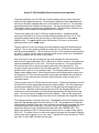
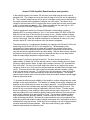
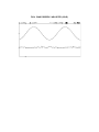
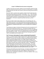
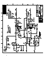
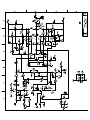
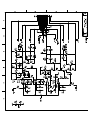
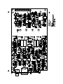
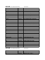
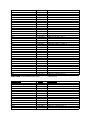
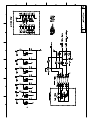
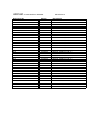
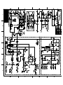
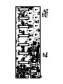
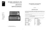
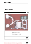
DiVA
Service
Manual
Issue 1.0
P1000 Amplifier
ARCAM
Bringing music & movies to life
Arcam P-1000 Amplifier Board functions and operation
The power amplifiers in the P-1000 are of class H design and use a three rail power
supply for high operating efficiency. These amplifier boards are field replaceable and
the unit can be safely operated with one or more boards out of the unit. The operating
descriptions below are divided into three groups. The input and signal control section.
The amplifier section and the power switching section. Signal net name references as
they appear in the schematic are designated here in bold type.
The line level audio path of the P-1000 very simple and short. Unbalanced audio
sources are buffered by U6-A and summed with the balanced input from U1-A. The
signal then passes through the gain set stage of U6-B and then on to the AMP-IN
amplifier drive. The AMP-IN signal is also contoured by U2-A and on to the power
switching section via the COMM output.
The gain switch S1 works by changing the local feedback around U6-B and has three
settings. The “A” gain position provides an overall gain of 31.5 dB and is compatible
with other Arcam amplifiers. The “B” setting is for use in THX compliant systems and the
low gain “C” position can be used to lower the overall system noise level in installations
where the speakers are very close to the listener.
Also at the input of the gain set stage are the mute transistor Q1 and the resistive
element of the clipping eliminator circuit. When the P-1000 is turned on, the global mute
signal at the MUTE input of U3-A is low. This forces its output to +12V which activates
the mute transistor Q1 as well as the clipping eliminator circuit through D15. The
FLT_OUT from the emitter follower Q24 and also goes high. Q1 then shunts the audio to
ground and R11 goes to a low resistance state. The FLT_OUT passes on out to the
channel status display board. When the global mute cycle finishes and the output from
U3-B goes low, Q1 turns off and passes the audio signal immediately but the resistive
element R11 has a slow release time which allows the audio output to ramp up in a
controlled manner.
The local mute circuit of U3-B also has two other inputs. The thermal shutdown circuit of
U2-B and R22 monitor the heatsink temperature of the amplifier. If the HS temperature
exceeds approximately 95 Deg C, the output of U2-B goes high and toggles the local
mute circuit on. Because of the hysteresis around U2-B, the thermal protection will
remain active until the amplifier has cooled down approximately 20 Deg below the trip
point. The second input is the PROT line from the amplifier. This is a fast acting input
which goes to a low impedance state if a short circuit is detected at the amplifier output.
The clipping eliminator circuit has two inputs. The AMPOUT monitors the amplifier output
signal and the OPA-OUT signal from the output of U1-B. The OPA-OUT line is inside the
overall amplifier feedback loop and is very sensitive to any differences between the input
and output signals in the audio path. If the unit is driven into clipping the difference
signal from these two lines is amplified and used to drive the CLM5000 LDR. This
causes the resistance of R11 to decrease and work as part of a voltage divider against
R85 or R5. The effect of this is to reduce the signal level going into the amplifier thereby
reducing the output clipping to a very low value. Typically this circuit will hold the THD to
less than 1% with 10dB of overdrive at the input.
Arcam P-1000 Amplifier Board functions and operation
In the amplifier portion of the board, Q2 acts as a level shifter and drives the class A
transistor Q13. The voltage source for the class A stage is from Q14 and is regulated by
Z1. This constant voltage causes Q13 to act as a constant current source and stabilizes
the output transistor bias regardless of changes in the AC mains. The class A drive
voltage is also removed from Q13 anytime the local or global mute circuits are activated.
In the un-muted state CLA-MUTE is –12V. When activated this line goes high to +12V
which removes Q14s base voltage when Q25 is turned on.
The bias temperature tracking is from diode D8 and the initial setting is made by
adjusting RP1 for a voltage reading of .5 to 1.0 mV across either R51-R53 or R44-R45
after the unit has been on and running for a minute or two. A better method of setting
the bias is to use a distortion analyzer and adjust the amplifier output for 1 volt at 2 kHz
into an 8 Ohm load. After the amplifier has been on and allowed to warm up for a few
minutes, adjust RP1 until the crossover notch just starts to disappear.
The output section is a complimentary feedback pair topology with Q9 and Q7,Q8 in the
positive leg and Q12 and Q10,Q11 in the negative leg. The advantage of this
configuration is higher peak output voltage and, because the emitters of the driver
transistors become the effective output of the amplifier, crossover discontinuities are
very fast and almost negligible without any bias setting. With the bias correctly adjusted
the transition through the crossover region is seamless and the very low bias current
holds the output stage dissipation to approximately 1 watt.
Output stage V-I limiting is through Q5 and Q6. The short circuit current limit is
approximately 10 Amps and is set to this high value in order to handle the out of phase
currents in highly reactive loads. At high output voltages, however, R37 increases this
limit to 20 Amps. For short circuit loads where the current is very high but the output
voltage is close to zero, Q4 is turned on and the PROT line activates the local signal mute
circuit. This mute removes the output signal momentarily and then releases, cycling
on/off until the fault is removed. To verify the short circuit protection, drive the amplifier
to an output of 5 volts or more and short the output terminals together. The shorted
channel output should cycle on and off and the front panel status indicator should toggle
between green and amber.
To increase the efficiency and reliability of the amplifier, multiple voltage rails are made
available to the output transistors. This addition of variable power supply voltages to the
amplifier circuit creates what is known as a class H amplifier. In conventional amplifiers
the output devices are simultaneously exposed to high voltage and high current. The
product of this current and voltage is dissipated in the form of heat. To make matters
worse, the efficiency of the amplifier is the poorest at lower power output levels. To side
step this problem the class H amplifier greatly improves the efficiency by running at low
power supply voltages when the signal level is low. The operating voltages increase
only as required by the program material. Another benefit is in the form of reliability
under demanding conditions. Because the output transistors are never exposed to the
maximum positive and negative supply voltages at the same time, the amplifier is able to
withstand both very high current, under short circuit conditions, as well as highly reactive
currents presented by some speakers. With the overall efficiency gain, amplifier
heatsink requirements are reduced by half.
Arcam P-1000 Amplifier Board functions and operation
With the amplifier operating at low output levels (<20 W) only the +/-20V low voltage rails
are used. As the output requirements increase, the COMM signal from U2-A also
increases and the peak value of this signal is compared to the low rail reference voltage
at the comparators U4-A and U5-B. When the peak value of the COMM signal exceeds
the reference the comparators will toggle on and the middle rail voltage will be supplied
to the amplifier. For a positive signal, Q15 and Q17 turn on the 40 volt supply and on
the negative swing Q23 and Q19 supply –40 volts.
As the requirements continue to increase the same sequence takes place for the +/- 60
volt supplies. U4-B, Q16 and Q18 supply the positive voltage and U5-A, Q22, Q20 and
Q21 supply the negative voltage. The power diodes D7,D23 and D24,D25 isolate the
high voltage supplies from the lower voltage supplies. Under short circuit conditions the
COMM line signal goes to zero because of the mute drive to Q1 and only the low voltage
supply is present at the output transistors.
To verify the correct operation of the commutator circuits drive the amplifier to 30-35
Vrms into an 8 Ohm load at 200 Hz and observe the positive and negative supplies. The
positive rail voltage is monitored at the emitter of Q18 or at the junction of D7, D23
(cathode ends). To monitor the negative rail use TP2 which is connected to the junction
of D24, D25. The waveforms should appear as shown in figure XX. If any of the rail
voltages fail to operate, the output of the amplifier will be limited to a lower value by the
clipping eliminator circuit. Because of this and the fact that the output will still be a sine
wave, it may be necessary to remove the 8 Ohm load to determine which rail is not
switching.
FIGURE 1
POSITIVE RAIL SWITCHING WAVEFORM
FIGURE 2
FIGURE 3
NEGATIVE GOING WAVEFORM
BIAS CONTROL AT MAX CCW POSITION
FIG 4 BIAS PROPERLY ADJUSTED (COLD)
P-1000 Display Board functions and operation.
The P-1000 display functions are divided into two separate blocks, power on/off and
channel status indications. The power on/off LED indicators are driven by the Standby
Power supply on the main board and are active any time the P-1000 is connected to the
AC mains supply and the rear panel power switch is on. The Channel Status LEDs
receive power from both the Main power supply and from each individual amplifier
channel.
With the P-1000 connected to the AC mains with the power switch on, the PWR-LED line
is high which turns on the red Standby LED on. It also turns Q2 on which forces the run
LED off.
When the unit is turned on via the front panel power button or the rear panel 12V trigger
PWR-LED line goes low and +12V from the main power supply turns on the green run
LED.
The amplifier channel status LEDs, at turn on, are driven by the FLT lines and show
amber for approximately 2 seconds. When the turn on mute cycle has finished the FLT
lines go low and the LEDs receive their power from the –12V supply and are illuminated
green.
If one of the amplifier channels becomes hot enough to thermal out the FLT line for that
channel will go high until that amplifier channel cools down. During the off time the
status led will show amber. Other channels are not affected by this action.
If one of the amplifier channels has a short circuit across the output terminals the FLT
line will be activated momentarily and the status LED will alternate between amber and
green. This amber/green cycle will continue as long as the fault is present and the
amplifier is trying to run program material. When the fault is removed the LED for that
channel will return to a steady green. No other channels are affected by this action.
In the event of a DC offset fault from the amplifier, the OFFSET line goes high which turns
on both LEDs and the color changes to a steady amber. A DC fault condition will also
shut down the main power supply. This removes the power to the status LEDs and all
the channel indicators will go off. Although it very unlikely that a DC fault will ever take
place, it does trigger a latching circuit that receives its power from the standby supply.
This means that it will be unaffected by the front power button or the rear panel 12V
trigger. The only way to clear this condition is to completely remove the power either by
turning the unit off via the rear panel power switch or by disconnecting the AC mains
cord for a few minutes. This allows the offset latching circuit to reset to the off state.
Arcam P-1000 Main Board functions and operation
In addition to the high current supply voltages for the seven amplifier channels, the Main
board also contains the circuitry for power on/off control, DC fault protection, the standby
housekeeping power and other control circuits as well as the bussing interconnections to
all channels.
Since the P-1000 is a multi rail class H amplifier, the Main board has three high power
plus/minus voltage supplies for the amplifier output stages. The +/- 12V for the signal
level amplifier circuits is obtained from the +/- 20 volt low rail supply. These 20 volt low
rails are also fused for added DC fault protection but under no operational conditions
including amplifier output short circuits should these fuses ever fail. The middle (+/40V) and high (+/- 60V) rails are capacitive input filters and require no further
explanation.
Because the middle and high voltage supplies have no direct discharge path to the
output stages when the unit is turned off, Q8 and Q9 form dynamic discharge resistors.
This serves two purposes. First it discharges the main bulk capacitors when the unit is
off and second, this energy is redirected to the +/- 12-volt supplies which eliminates turn
off irregularities. Q8 and Q9 function only for a minute or so when the unit is powered
down.
The standby power supply is functional at all times when the unit is connected to the AC
mains and the rear panel power switch is on. The function of the STBY supply is to
provide power for the power on/off logic, display and the DC fault circuit. One additional
function is to supply the amplifier circuits with a small (less than 1 volt) DC negative bias
which eliminates turn on “pops”. This is accomplished through R62 and D15. Because
the power requirements of these circuits is so low the power consumption when the P1000 is in the standby mode is less than 2 watts.
The DC fault circuit, which includes Q2, 3 and 4, is a bi-directional DC level sensing
circuit. The output of each amplifier is monitored through the CH1 through CH7 R-C
networks. If a positive going DC voltage is present on any of these inputs, Q2 becomes
forward biased, turns on and forces Q3 on. Likewise, for a negative going DC fault Q2
operates in a common base mode with R12 holding the base close to ground potential
while the emitter goes negative and the circuit is again activated. Because of the
positive feedback through R26, Q3 latches on and, through Q4, pulls the base of the
emitter follower Q7 to ground. This action shuts down the Opto coupler U3 and the main
power supply Triac goes to the off state and turns the P-1000 off. The OFFSET line
drives the global mute circuit and the power LED will show as amber. The unit will
remain in this shutdown mode until all power is removed for a minute or so until the
standby voltage drops close to zero. If the offset circuit is activated, LED D12 on the
main board will be on and serve as a visual indication that the unit is in shutdown mode.
Shorting TP1 and TP2 together on the main board will force the circuit to reset.
The power on/off switching can be done three ways. Turning the rear panel switch on or
off, pressing the front panel power button (assuming the rear panel switch is on) or by
applying a 12 volt DC trigger to the rear panel 3.5 MM jack. The logic switching
functions of the P-1000 are then controlled by U1 and U2 which maintain a zero crossing
on/off drive to the main triac.
Arcam P-1000 Main Board functions and operation
To perform these functions an AC mains sine wave from the standby transformer
secondary is applied to the input of U2-D. This LV_AC_IN signal is then half wave
rectified and the output of gate U2-D is a square wave clock signal to the CLK input of
U-1B. By using a clock signal derived from the AC mains, zero crossing turn on/off is
assured regardless of which method is used. If the unit is turned on via the rear panel
power switch the SET input of U1-A goes high and the Q output becomes the DATA
input to U1-B whose Q output goes high on the first clock cycle from U2-D. This high
output then turns on the Optocoupler U3 and the main triac is gated on thereby turning
¯ output is
on the main power. If the front panel power button is pressed again, the Q
clocked through the DATA input of U1-A causing its Q output to go low. This low state is
passed through U1-B, on to the Opto and the unit is turned off. Since U1-A is a divide
by 2 circuit subsequent button presses will switch the unit on and off. The PWR_LED line
from U1-A drives the front panel standby LED and the PWR_ON line is used to supply
power to Q5 in the power on/off mute circuit.
The rear panel 12 volt remote input is independent of the front panel power button and
will cycle the unit on or off depending on the whether a 12 volt input is present. The
remote switching, unlike the front panel switching, is voltagelevel dependent and
operates by forcing a SET or RESET on U1-A. The main power triac switching,
however, is still controlled by the clock signal from U2-D. The rear panel control also
incorporates a time delay of 1-2 seconds through the R-C pair R2-C4. This allows for a
staggered turn on sequence if an entire system is powered on by a single 12 volt trigger
source.
Because triacs and SCRs remain conductive only when a current is flowing through
them, a constant load circuit is included on the transformer secondary windings. The RC network of R64 on the 20 volt winding and the 3 uF 250V capacitor across the 60 volt
windings correct this by holding the triac on through the zero crossing point. This
equalizes the transformer flux and prevents mechanical transformer “buzz” due to
unequal conduction cycles across the windings.
When the P-1000 is turned on, the global mute circuit is activated by the network around
Q5. Initially Q5 will be off and the MUTE output will be –12 V. This mute voltage is
distributed to all seven channels and will activate the local mute circuit on each of the
amplifier boards. As C30 discharges, the voltage eventually exceed the zener drop of
Z4 and turn Q5 on which then toggles high for a MUTE line voltage of –4V. When the
global mute line is high (-4V), the individual channels are active and will pass a signal.
The FLT outputs from the amplifier boards are used to provide the channel status LED
drive. If any amplifier channel is in the muted state its FLT output is high and the
corresponding channel status LED will show as amber.
As shipped the P-1000 is meant to operate at either 230Vac or 120Vac. To change the
AC mains operating voltage it is necessary to replace the main power transformer with
one of the desired voltage. In addition it is also required that the standby transformer
primary windings are rewired to accept the new voltage. JP1,JP2 and JP3 determine
which voltage the standby transformer is set for. For 230Vac operation JP1 is used and
JP2 and 3 are removed. For 120Vac operation JP2 and 3 are installed and JP3 is
removed. The fuse F1 is an F50mAL type and remains the same value for either
voltage.
ARCAM P-1000 AMPLIFIER BOARD
Reference No
CAPACITOR
C1 C45
C2
C3
C4 C22 C23 C39 C42
C5
C6
C7 C25 C36 C37 C43 C46 C47 C48
C8
C9
C10 C32 C33 C34 C35 C40 C41
C11 C15
C12 C13 C49
C16 C26 C27 C28 C29
C17 C18 C19 C20
C21
C24
C30 C31
C38
C44
C50
C51
DIODE
D1 D2 D3 D4 D5 D6 D9 D10 D11 D12
D7 D23 D24 D25
D8
D13
D16 D19 D20 D21 D22
TRANSISTOR
Q1
Q2 Q4 Q5 Q15 Q16 Q22 Q23
Q3 Q14
Q6 Q20 Q24 Q25
Q7 Q8
Q9 Q13
Q10 Q11
Q12
Q17 Q19
Q18
Q21
RESISTOR
C14
R1
Part No
Description
205-813-4
210-311-4
206-529-4
203-038-4
205-509-4
203-002-4
203-027-4
203-015-4
203-019-4
205-505-4
203-031-4
205-317-4
201-125-4
201-013-4
203-036-4
201-015-4
224-012-3
201-015-4
203-043-4
201-121-4
CAP EL RADIAL 47uF 100V
CAP EL NP 22uF 25V
CAP EL RADIAL .22uF 50V
CAP CERAMIC 330pF 1KV 20%
CAP EL RADIAL 10uF 50V
CAP CERAMIC 5pF 1KV 20%
CAP CERAMIC 100pF 1KV 20% NP0
CAP CERAMIC 27pF 1KV 20% NP0
CAP CERAMIC 47pF 1KV 20%
CAP EL RADIAL 2.2uF 50V
CAP CERAMIC 180pF 1KV 20% NP0
CAP EL RADIAL 220uF 25V
CAP MYLAR .1uF 100V 10%
CAP MYLAR .01uF 50V 10%
CAP CERAMIC 270pF 1KV 20%
CAP MYLAR .015uF 50V 10%
CAP CERAMIC 22pf 50V 20% AX .35"
CAP MYLAR .015uF 50V 10%
CAP CERAMIC 470pF 1KV 20%
NOT USED
CAP MYLAR .047uF 100V 10%
302-001-4
304-008-0
301-001-1
302-006-0
301-001-4
DIODE 1N4148 SIGNAL .4"
DIODE FAST REC 5A
DIODE 4004 1A 400V UN-PREP
DIODE FDH400 HV SIGNAL .4"
RECT 1N4004 1A 400V .4"
311-015-0
311-010-0
311-003-0
311-009-0
312-014-0
312-012-0
312-015-0
312-013-0
314-001-0
312-001-0
312-002-0
TRANS 2SC2878 NPN TO-92 ECB
TRANS MPSA56 PNP TO-92
TRANSISTOR MPSW06 NPN 1W
TRANS MPSA06 NPN TO-92
TRANSISTOR MJW21193 PNP PWR 250V
TRANS 2SC4793 NPN TO220
TRANSISTOR MJW21194 NPN PWR 250V
TRANS 2SA1837 PNP TO-220
TRANSISTOR IRFZ34 PWR FET
TRANSISTOR TIP35C NPN PWR 100V
TRANSISTOR TIP36C PNP PWR 100V
103-051-4
109-289-4
RES CF 1/4W 5% 130 OHM .4"
RES MF 1/4W 1% 10.0K .4"
ARCAM P-1000 AMPLIFIER BOARD
Reference No
RESISTOR
R2
R3
REVISION A
REVISION A
Part No
Description
109-289-4
109-289-4
RES MF 1/4W 1% 10.0K .4"
RES MF 1/4W 1% 10.0K .4"
Reference No
R4
R5
R6
R7
R8
R9
R10
R11
R12
R13
R14
R15
R16
R17
R18
R19
R20
R21
R23
R24
R25
R26
R27
R28
R29
R30
R31
R32
R33
R34
R35
R36
R37
R38
R39
R40
R41
R42
R43
R44
R45
R46
Part No
109-289-4
103-072-4
103-094-4
103-107-4
109-318-4
103-113-4
103-103-4
325-004-0
103-064-4
109-348-4
103-073-4
103-107-4
103-072-4
103-103-4
103-100-4
103-083-4
103-083-4
103-103-4
103-072-4
109-219-4
103-136-4
109-235-4
103-096-4
103-073-4
103-101-4
103-028-4
116-019-0
116-019-0
109-354-4
103-060-4
103-080-4
103-039-4
105-088-5
103-059-4
103-059-4
103-045-4
103-052-4
103-008-4
103-008-4
114-004-0
114-004-0
103-064-4
ARCAM P-1000 AMPLIFIER BOARD
Reference No
R47
R48
R49
R50
R51
R52
R53
R54
R55
Part No
103-064-4
103-046-4
103-049-4
103-058-4
114-004-0
103-008-4
114-004-0
103-008-4
103-103-4
Description
RES MF 1/4W 1% 10.0 KOHM .4"
RES CF 1/4W 5% 1K .4"
RES CF 1/4W 5% 8.2K .4"
RES CF 1/4W 5% 30K .4"
RES MF 1/4W 1% 20.0K .4"
RES CF 1/4W 5% 51K .4"
RES CF 1/4W 5% 20K .4"
PHOTO RES
RES CF 1/4W 5% 470 OHM .4"
RES MF 1/4W 1% 41.2K .4"
RES CF 1/4W 5% 1.1K .4"
RES CF 1/4W 5% 30K .4"
RES CF 1/4W 5% 1K .4"
RES CF 1/4W 5% 20K .4"
RES CF 1/4W 5% 15K .4"
RES CF 1/4W 5% 3K .4"
RES CF 1/4W 5% 3K .4"
RES CF 1/4W 5% 20K .4"
RES CF 1/4W 5% 1K .4"
RES MF 1/4W 1% 1.87K .4"
RES CF 1/4W 5% 470K .4"
RES MF 1/4W 1% 2.74K .4"
RES CF 1/4W 5% 10K .4"
RES CF 1/4W 5% 1.1K .4"
RES CF 1/4W 5% 16K .4"
RES CF 1/4W 5% 15 OHM .4"
RES 1W MOF 5% 1.6K
RES 1W MOF 5% 1.6K
RES MF 1/4W 1% 47.5K .4"
RES CF 1/4W 5% 330 OHM .4"
RES CF 1/4W 5% 2.2K .4"
RES CF 1/4W 5% 43 OHM .4"
RES CF 1/2W 5% 4.7K OHM .5"
RES CF 1/4W 5% 300 OHM .4"
RES CF 1/4W 5% 300 OHM .4"
RES CF 1/4W 5% 75 OHM .4"
RES CF 1/4W 5% 150 OHM .4"
RES CF 1/4W 5% 2 OHM .4"
RES CF 1/4W 5% 2 OHM .4"
RES 5W WW 5% .2 OHM
RES 5W WW 5% .2 OHM
RES CF 1/4W 5% 470 OHM .4"
REVISION A
Description
RES CF 1/4W 5% 470 OHM .4"
RES CF 1/4W 5% 82 OHM .4"
RES CF 1/4W 5% 110 OHM .4"
RES CF 1/4W 5% 270 OHM .4"
RES 5W WW 5% .2 OHM
RES CF 1/4W 5% 2 OHM .4"
RES 5W WW 5% .2 OHM
RES CF 1/4W 5% 2 OHM .4"
RES CF 1/4W 5% 20K .4"
Reference No
R56
R57
R58
R59
R60
R61
R62
R63
R64
R65
R66
R67
R68
R69
R70
R71
R72
R73
R74
R75
R76
R77
R78
R79
R80
R81
R82
R83
R84
R85
R86
R87
R88
R89
R90
R91
Part No
111-004-0
103-072-4
103-072-4
103-072-4
103-096-4
103-074-4
116-019-0
103-086-4
103-072-4
103-089-4
103-072-4
103-089-4
103-072-4
103-072-4
116-010-0
103-104-4
103-052-4
103-103-4
109-220-4
103-072-4
103-098-4
103-103-4
109-220-4
103-072-4
109-289-4
103-096-4
103-103-4
103-055-4
109-228-4
109-289-4
109-318-4
103-080-4
116-018-0
103-104-4
103-103-4
103-113-4
ARCAM P-1000 AMPLIFIER BOARD
Reference No
R92
R93
R95
R96
R97
R98
R99
R101
R102
R103
R104
R105
R106
R107
R110
Part No
103-113-4
103-098-4
109-321-4
103-124-4
103-124-4
103-052-4
109-225-4
103-079-4
103-024-4
103-072-4
103-065-4
103-059-4
103-059-4
103-089-4
103-071-4
Description
RES MOF 2W MOX 5% 10 OHM
RES CF 1/4W 5% 1K .4"
RES CF 1/4W 5% 1K .4"
RES CF 1/4W 5% 1K .4"
RES CF 1/4W 5% 10K .4"
RES CF 1/4W 5% 1.2K .4"
RES 1W MOF 5% 1.6K
RES CF 1/4W 5% 3.9K .4"
RES CF 1/4W 5% 1K .4"
RES CF 1/4W 5% 5.1K .4"
RES CF 1/4W 5% 1K .4"
RES CF 1/4W 5% 5.1K .4"
RES CF 1/4W 5% 1K .4"
RES CF 1/4W 5% 1K .4"
RES CF 1W 5% 1.2K .4"
RES CF 1/4W 5% 22K .4"
RES CF 1/4W 5% 150 OHM .4"
RES CF 1/4W 5% 20K .4"
RES MF 1/4W 1% 1.91K .4"
RES CF 1/4W 5% 1K .4"
RES CF 1/4W 5% 12K .4"
RES CF 1/4W 5% 20K .4"
RES MF 1/4W 1% 1.91K .4"
RES CF 1/4W 5% 1K .4"
RES MF 1/4W 1% 10.0 KOHM .4"
RES CF 1/4W 5% 10K .4"
RES CF 1/4W 5% 20K .4"
RES CF 1/4W 5% 200 OHM .4"
RES MF 1/4W 1% 9.76K .4"
RES MF 1/4W 1% 10.0K .4"
RES MF 1/4W 1% 20.0K .4"
RES CF 1/4W 5% 2.2K .4"
RES MOX 5.1 OHM 1W
RES CF 1/4W 5% 22K .4"
RES CF 1/4W 5% 20K .4"
RES CF 1/4W 5% 51K .4"
REVISION A
Description
RES CF 1/4W 5% 51K .4"
RES CF 1/4W 5% 12K .4"
RES MF 1/4W 1% 21.5K .4"
RES CF 1/4W 5% 150K .4"
RES CF 1/4W 5% 150K .4"
RES CF 1/4W 5% 150 OHM .4"
RES MF 1/4W 1% 13.3K .4"
RES CF 1/4W 5% 2K .4"
RES CF 1/4W 5% 10 OHM .4"
RES CF 1/4W 5% 1K .4"
RES CF 1/4W 5% 510 OHM .4"
RES CF 1/4W 5% 300 OHM .4"
RES CF 1/4W 5% 300 OHM .4"
RES CF 1/4W 5% 5.1K .4"
RES CF 1/4W 5% 910 OHM .4"
Reference No
IC
U1
U2 U3 U6
U4 U5
ZENER
Z1
Z2
Z3 Z4
L1
CONNECTOR
J1
J2
J3 J5
CON1
MISC
S1
TP1 TP2 TP3 TP4
RP1
R22
JACK PLATE
Part No
Description
322-010-0
322-007-0
322-029-0
IC TLO82 DUAL OPAMP
IC 4560 DUAL OPAMP DIP
IC LM393 DUAL COMP
303-025-0
303-004-0
303-010-0
353-007-0
DIODE ZEN 4758 54V .4"
DIODE ZEN 4738 8.2V .4"
DIODE ZEN 4754 39V .4"
INDUCTOR 6UH AXIAL
454-008-0
446-020-0
421-010-0
445-016-0
XLR FEMALE R/A PCB MT TYPE A
RCA JACK DUAL VERTICAL
FASTON 250
CONN 13 PIN/ST/ .156 TIN
470-023-0
445-015-0
147-001-0
170-001-4
633-301-0
SWITCH SLIDE SP3T HORZ
TEST POINT 1 PIN
POT ROTARY 10mm 5K H-ADJ
THERMISTOR 10K NTC .4"
INPUT JACK MTG PLATE
ARCAM
P-1000 DISPLAY BOARD
Reference No
DIODE
D1
D9 D10 D11
D2 D3 D4 D5 D6 D7 D8
TRANSISTOR
Q1 Q2
RESISTOR
R1
R2
R3
R4
R5
R6
R7
R8
R9
R10
R11
R12
R13
R14
R15
R16
R17
R18
R19
MISC
J1
RB1-RB2
SW1
BRACKET RA
SPACER
BUTTON
JACK
STANDOFF
REVISION A
Part No
Description
307-010-0
302-001-4
307-010-0
DIODE LED YEL/GRN
DIODE 1N4148 SIGNAL .4"
DIODE LED YEL/GRN
311-009-0
TRANS MPSA06 NPN TO-92
103-024-4
103-024-4
103-024-4
103-024-4
103-024-4
103-024-4
103-024-4
103-076-4
103-076-4
103-076-4
103-076-4
103-076-4
103-076-4
103-076-4
103-112-4
103-076-4
103-071-4
103-076-4
103-112-4
RES CF 1/4W 5% 10 OHM .4"
RES CF 1/4W 5% 10 OHM .4"
RES CF 1/4W 5% 10 OHM .4"
RES CF 1/4W 5% 10 OHM .4"
RES CF 1/4W 5% 10 OHM .4"
RES CF 1/4W 5% 10 OHM .4"
RES CF 1/4W 5% 10 OHM .4"
RES CF 1/4W 5% 1.5K .4"
RES CF 1/4W 5% 1.5K .4"
RES CF 1/4W 5% 1.5K .4"
RES CF 1/4W 5% 1.5K .4"
RES CF 1/4W 5% 1.5K .4"
RES CF 1/4W 5% 1.5K .4"
RES CF 1/4W 5% 1.5K .4"
RES CF 1/4W 5% 47K .4"
RES CF 1/4W 5% 1.5K .4"
RES CF 1/4W 5% 910 OHM .4"
RES CF 1/4W 5% 1.5K .4"
RES CF 1/4W 5% 47K .4"
445-023-0
415-024-0
470-024-0
561-006-0
541-022-0
581-053-0
447-004-0
533-004-0
HDR 10 x 2 .1 RA GOLD
RIBBON CABLE
SPST MOMETARY CONTACT
RIGHT ANGLE MTG BRACKET
USE WITH D1-D7
PWR ON/OFF
3.5 MM MONO FOR 12V TRIGGER
.25" NYLON STANDOFF FOR PCB MTG
ARCAM P-1000 MAIN BOARD
Reference No
CAPACITOR
C1 C2
C3 C9 C51
C4 C10 C30
C5 C55
C6
C7 C8
C11 C12 C33 C34 C35 C36 C37 C38
C39 C40 C41 C42 C43 C44
C15 C16
C17 C18 C19 C20 C21 C22
C23 C24
C25 C26 C27 C28
C29
C31
C32 C50
C45 C46 C47 C48 C49 C52 C53
C54 C63
C56
R4 - CAP USED IN THIS POSITION
REVISION A
Part No
Description
202-101-4
202-124-4
205-509-4
205-315-4
205-517-1
210-307-4
205-513-4
CAP MYLAR .001uF 100V 5%
CAP MYLAR .082uF 100V 5%
CAP EL RADIAL 10uF 50V
CAP EL RADIAL 100uF 25V
CAP EL RADIAL 220uF 50V
CAP EL NP 47uF 25V
CAP EL RADIAL 47uF 50V
240-057-4
205-781-0
205-580-4
205-422-4
240-025-0
205-221-4
205-505-4
206-503-4
205-517-1
202-113-4
206-503-4
CAP CERAMIC .0022 250V
CAP EL RADIAL 10000uF 80V
CAP EL RADIAL 15000uF 50V
CAP EL RADIAL 2200uF 35V
CAP UL-CSA LINE CAP
CAP EL RADIAL 1000uF 16V
CAP EL RADIAL 2.2uF 50V
CAP EL RADIAL 1.0uF 50V
CAP EL RADIAL 220uF 50V
CAP MYLAR .01uF 100V 5%
CAP EL RADIAL 1.0uF 50V
302-001-4
DIODE 1N4148 SIGNAL .4"
DIODE
D1 D2 D3 D6 D7 D8 D9 D10 D15
D20 D21 D22 D23 D24 D25 D27 D29
D41
D4 D5 D11 D13 D14 D26 D28 D30
D32 D33 D40
D12
D16 D17 D18 D19
D31
D34-D39
Z1 Z2
Z3
Z4 Z5 Z6
Z7
301-001-4
RECT 1N4004 1A 400V .4"
307-001-0
304-008-0
N/A
N/A
303-002-0
303-001-0
303-004-0
303-001-0
DIODE LED RED
DIODE FAST REC 5A
NOT USED
NOT USED
DIODE ZEN 4742 12V 1W .4"
DIODE ZEN 4740 10V .4"
DIODE 4738 ZEN 8.2V 1W .4"
DIODE ZEN 4740 10V .4"
TRANSISTOR
Q1 Q6
Q2 Q4 Q7
Q3 Q5
Q8
Q9
311-011-0
311-009-0
311-010-0
312-012-0
312-013-0
TRANS 2N4401 NPN TO-92
TRANS MPSA06 NPN TO-92
TRANS MPSA56 PNP TO-92
TRANS 2SC4793 NPN TO220
TRANS 2SA1837 PNP TO-220
ARCAM P-1000 MAIN BOARD
Reference No
RESISTOR
R1
R2
Part No
106-001-0
103-120-4
REVISION A
Description
RES CF 1/2W 5% 2.2M
RES CF 1/4W 5% 100K .4"
Reference No
R3
R4 SEE CAPACITORS
R5
R6
R7
R8
R9
R10
R11
R12
R13
R14
R15
R16
R17
R18
R19
R20
R21
R22
R23
R24
R25
R26
R27
R28
R29
R30
R31
R32
R33
R34
R35
R36
R37
R38
R39
R40
R41
Part No
103-123-4
Description
RES CF 1/4W 5% 130K .4"
103-136-4
103-136-4
103-113-4
103-103-4
103-089-4
103-096-4
103-081-4
103-103-4
103-121-4
103-096-4
103-096-4
103-116-4
103-116-4
103-116-4
103-116-4
103-116-4
103-113-4
103-113-4
103-113-4
103-103-4
103-103-4
103-096-4
103-089-4
103-111-4
103-092-4
103-111-4
103-092-4
103-111-4
103-092-4
103-111-4
103-092-4
103-111-4
103-072-4
103-024-4
103-024-4
101-096-0
103-111-4
RES CF 1/4W 5% 470K .4"
RES CF 1/4W 5% 470K .4"
RES CF 1/4W 5% 51K .4"
RES CF 1/4W 5% 20K .4"
RES CF 1/4W 5% 5.1K .4"
RES CF 1/4W 5% 10K .4"
RES CF 1/4W 5% 2.4K .4"
RES CF 1/4W 5% 20K .4"
RES CF 1/4W 5% 110K .4"
RES CF 1/4W 5% 10K .4"
RES CF 1/4W 5% 10K .4"
RES CF 1/4W 5% 68K .4"
RES CF 1/4W 5% 68K .4"
RES CF 1/4W 5% 68K .4"
RES CF 1/4W 5% 68K .4"
RES CF 1/4W 5% 68K .4"
RES CF 1/4W 5% 51K .4"
RES CF 1/4W 5% 51K .4"
RES CF 1/4W 5% 51K .4"
RES CF 1/4W 5% 20K .4"
RES CF 1/4W 5% 20K .4"
RES CF 1/4W 5% 10K .4"
RES CF 1/4W 5% 5.1K .4"
RES CF 1/4W 5% 43K .4"
RES CF 1/4W 5% 6.8K .4"
RES CF 1/4W 5% 43K .4"
RES CF 1/4W 5% 6.8K .4"
RES CF 1/4W 5% 43K .4"
RES CF 1/4W 5% 6.8K .4"
RES CF 1/4W 5% 43K .4"
RES CF 1/4W 5% 6.8K .4"
RES CF 1/4W 5% 43K .4"
RES CF 1/4W 5% 1K .4"
RES CF 1/4W 5% 10 OHM .4"
RES CF 1/4W 5% 10 OHM .4"
RES CF 1/8W 5% 10K .35"
RES CF 1/4W 5% 43K .4"
Part No
103-123-4
103-072-4
103-136-4
103-103-4
103-089-4
103-083-4
103-024-4
REVISION A
Description
RES CF 1/4W 5% 130K .4"
RES CF 1/4W 5% 1K .4"
RES CF 1/4W 5% 470K .4"
RES CF 1/4W 5% 20K .4"
RES CF 1/4W 5% 5.1K .4"
RES CF 1/4W 5% 3K .4"
RES CF 1/4W 5% 10 OHM .4"
ARCAM P-1000 MAIN BOARD
Reference No
R42
R43
R44
R45
R46
R47
R48
Reference No
R49
R50
R51
R52
R53
R54
R55
R56
R57
R58
R59
R60
R61
R62
R63
R64
R65
R66
R67
R68
R69
R70
R71
R72
R73
R74
R75
R100
R101
Part No
103-111-4
103-092-4
103-116-4
103-111-4
103-092-4
103-072-4
103-096-4
103-076-4
103-092-4
103-123-4
103-123-4
103-123-4
103-123-4
103-082-4
103-048-4
114-007-0
116-006-0
115-003-6
105-100-4
105-100-4
114-007-0
114-008-0
117-002-6
117-002-6
114-007-0
114-007-0
103-089-4
103-116-4
103-123-4
Description
RES CF 1/4W 5% 43K .4"
RES CF 1/4W 5% 6.8K .4"
RES CF 1/4W 5% 68K .4"
RES CF 1/4W 5% 43K .4"
RES CF 1/4W 5% 6.8K .4"
RES CF 1/4W 5% 1K .4"
RES CF 1/4W 5% 10K .4"
RES CF 1/4W 5% 1.5K .4"
RES CF 1/4W 5% 6.8K .4"
RES CF 1/4W 5% 130K .4"
RES CF 1/4W 5% 130K .4"
RES CF 1/4W 5% 130K .4"
RES CF 1/4W 5% 130K .4"
RES CF 1/4W 5% 2.7K .4"
RES CF 1/4W 5% 100 OHM .4"
RES 5W WW 5% 240 OHM
RES MOX 2W 5% 240 OHM
RES MOX 3W 5% 820 OHM
RES CF 1/2W 5% 15K .6"
RES CF 1/2W 5% 15K .6"
RES 5W WW 5% 240 OHM
RES 5W WW 5% 510 OHM
RES MOX 2W 5% 820 OHM
RES MOX 2W 5% 820 OHM
RES 5W WW 5% 240 OHM
RES 5W WW 5% 240 OHM
RES CF 1/4W 5% 5.1K .4"
RES CF 1/4W 5% 68K .4"
RES CF 1/4W 5% 130K .4"
IC
U1
U2
U3
U4
U5
321-002-0
321-009-0
325-002-0
324-002-0
324-001-0
Dual D-Flip-Flop
IC4093 QUAD NAND GATE
IC MCO3011 OPTOCOUPLER DIP6
IC 7912 LINEAR REG 12V NEG
IC 7812 LINEAR REG 12V POS
ARCAM P-1000 MAIN BOARD
Reference No
MISC
CON7-10 14 20 25
F1
F2 F3
IND1
J1
JP1 JP2 JP3
T1
TP1 TP2
Part No
444-048-0
461-011-0
461-009-0
353-007-0
445-022-0
119-001-4
354-100-0
445-015-0
REVISION A
Description
CON 156 RA ENTRY 12P
FUSE HOLDER PCB 5MM
FUSE CLIP ATC
INDUCTOR 6UH AXIAL
HDR 10Px2 .1 GOLD
JUMPER 1/4W BODY .4" PREP
XFMR 30V CT PCB MNT
TEST POINT 1 PIN
ARCAM P-1000
Item
1
15
20
25
25
30
35
40
45
50
55
60
65
70
75
80
90
95
105
110
125
130
135
140
145
150
155
165
180
185
195
200
215
220
220
230
235
240
255
265
270
305
315
330
335
Part Description
REVISION A
Part No
HEX NUT 10MM
LOCATING WASHER
RUBBER MTG GASKET
TRANSFORMER 800VA 115V
TRANSFORMER 800VA 230V
NUT 8-32 NYLOCK
MTG PLATE, TRANSFORMER
BOLT 10 x 115 MM
FOOT
SCREW SM #6 x 1/4
SCREW 8-32 x 1/2" PH
WELL NUT 8-32
WASHER #8 FLAT
SCREW 8-32 x 3/4 PH
SCREW 6-32 x 1/4 PH
FLEX TUBING 5/8" x 7.5"
FUSE T10AL MDA 10
SILPAD
PRESSURE PLATE
SCREW 6-32 x 1/2 PH
MAIN BOARD
KEP NUT #8
RECTIFIER 35A BR
CHASSIS, BLACK
LINE FILTER FERRITE CORE
SCREW SM #6 x 3/8
AMP BOARD
WASHER #6 INT
SPKR TERMINAL ASSY
SPEAKER CONN RED
SPEAKER CONN BLACK
REM 12V JACK PCB
FUSE T6.3AL
FUSE HOLDER
FUSE HOLDER
POWER CORD SOCKET
BUSS BAR COPPER
CAP 3.3UF 250VDC MYLAR
WEATHER STRIP FOAM TAPE
POWER SW PCB
SCREW 4-40 x 3/8 SOC HD
TRIAC 35 A
BUTTON PLASTIC
RIBBON ASSY 20 POS IDC
DISPLAY PCB ASSY
ARCAM P-1000
Item
FINAL ASSEMBLY
356-123-0
356-223-0
523-001-0
631-309-0
583-010-0
508-002-0
502-022-0
527-001-0
511-016-0
502-012-0
502-001-0
404-008-0
463-009-0
402-005-0
631-185-0
502-020-0
731-177-0
521-003-0
325-005-0
635-302-2
351-006-0
508-007-0
731-179-0
512-001-0
444-055-0
527-003-2
527-003-1
731-181-0
463-012-0
451-005-0
451-010-0
431-006-0
631-306-0
221-005-0
030-00X-0
731-181-0
504-002-0
318-001-0
581-046-0
416-029-0
731-181-0
FINAL ASSEMBLY
Where Used
SUPPLIED WITH TRANSFORMER
SUPPLIED WITH TRANSFORMER
SUPPLIED WITH TRANSFORMER
US/CAN MODEL
UK/EUR MODEL
XFMR MTG PLATE
USE WITH TRANSFORMER
SUPPLIED WITH TRANSFORMER
USE WITH BRIDGE RECT
XFMR MTG PLATE
XFMR MTG PLATE
XFMR MTG PLATE
USE TO MNT MAIN BD AND REM BD
USE OVER AC WIRING
US/CAN MODEL
USE WITH U4 U5
USE WITH U4-U5
USE WITH PRESS PLATE ON U4 U5
USE WITH BRIDGE RECT
MOUNT TO CHASSIS + FACING MAIN BD
MOUNT TO XFMR PRIMARY LEADS
USE TO MOUNT HS AND FP
MAIN BD MTG SCREWS
BLACK
TOP ROW
BOTTOM ROW
PART OF DISPLAY BD
UK/EUR MODEL
US/CAN MODEL
UK/EUR MODEL
ATTACH ACROSS XFMR BLUE LEADS
USE ALONG TOP EDGE OF CHASSIS
PART OF DISPLAY BD
USE WITH PWR SW PCB ASSY
MOUNT TO MAIN PCB
USE WITH PWR SW PCB ASSY
REVISION A
Part Description
Part No
Where Used
MASKING TAPE 1/2"
TAPE DBL BACK FOAM 1/8"
SHRINK TUBING .25"
030-007-0
030-002-0
404-003-0
USE ON INSIDE EDGE OF TOP COVER
USE UNDER LARGE CAPS
USE WITH AC WIRING
Item
Part Description
Part No
Where Used
WIRE 18GA TEW BLU 3.5"
WIRE 18GA TEW BLK 4"
WIRE 18GA TEW BLK 5.5"
WIRE 18GA TEW BLK 13.25"
FASTON FEM 18GA INSULATED
FASTON FEM 14GA INSULATED
TYWRAP
TYWRAP
FRONT PANEL BLK
FRONT PANEL SILVER
DAMPING PLATE
TOP COVER, BLACK
TOP COVER, SILVER
WIRE ASSY 18GA TEW 11.25"
WIRE ASSY 18GA TEW 12.25"
WIRE ASSY 18GA TEW 12.5"
WIRE ASSY 18GA TEW RED 4.25"
RIBBON CABLE 20 COND
CONNECTOR IDC 20 POS
413-030-0
413-031-0
413-032-0
413-033-0
421-002-0
421-014-0
584-003-0
584-025-0
606-022-X
606-022-X
631-316-0
635-304-X
635-304-X
704-053-0
704-054-0
704-055-0
704-056-0
415-020-0
444-033-0
USE WITH BRIDGE RECT
PWR SW TOP TO FUSE END TERM
PWR SW BOT TO AC LINE BOT
BUSS BAR TO WP18-19 ON MAIN BD
XFMR WIRING
LINE FILTER MTG
ATTACH TO INSIDE OF TOP COVER
AC LINE CONN TOP TO MAIN BD "L"
AC LINE GND TO MAIN BD "G"
FUSE HOLDER SIDE TO MAIN BD "N"
USE WITH RED JACKS
PART OF 416-029-0
PART OF 416-029-0