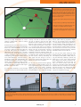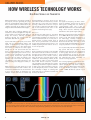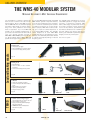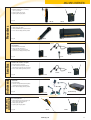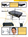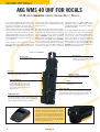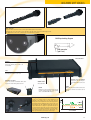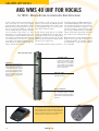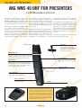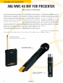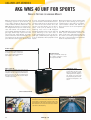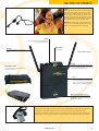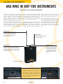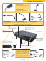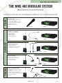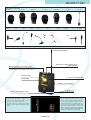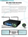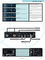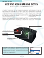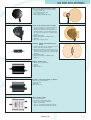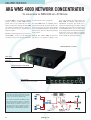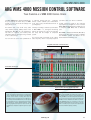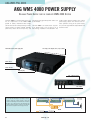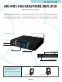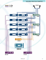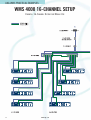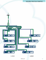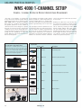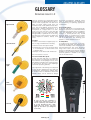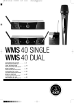
1
WMS 40
WMS 400
Wireless
Microphone
Systems
Everything you've always wanted to know
about AKG WIRELESS TECHNOLOGY.
WMS 4000
AKG PREFACE
WIRELESS TECHNOLOGY FOR THE FUTURE
A PIONEER IN ACOUSTICS FOR OVER 50 YEARS
As more and more affordable wireless
equipment became available, the
demand for high quality single and multichannel wireless systems for sound companies, conference centers, public buildings, and live sound grew sharply, too.
AKG responded to this trend early on,
developing a specific line of products RF technology in day-to-day work. It conand accessories that provides a profes- tains many helpful tips and tricks for
both professionals and first-time users.
sional solution for every application.
Wireless equipment from AKG will proviThis brochure explains the way wireless de a professional solution for any applisystems work to provide a better under- cation. This brochure makes it easier to
standing of how to make optimum use of get the best possible results.
“When it comes to studio, broadcast, or live sound equipment, choose AKG. The engineering competence and
worldwide reputation of the AKG brand give you the confidence of using equipment meeting the highest standards of quality and reliability.”
Dr. Hugo Lenhard-Backhaus, CEO, AKG Vienna
AKG Facts & Figures:
• Established in Austria in 1947
• Founders: Rudolf Görike
and Ernst Pless
• AKG grew from a two-man company
into a multinational company
• AKG has applied for more than
1,400 patents worldwide
• AKG is a leading audio manufacturer
with one of the most advanced
acoustics labs in Europe
For more than five decades, AKG has been
a leading manufacturer of studio microphones, broadcast and live sound equipment, as well as headphones to the highest standards of quality and reliability.
reputation and popularity of the legendary
AKG brand. Today, AKG products are available throughout the world and have become a standard in many radio and TV studios.
The resulting experience and engineering Did you know that according to the 1990
know-how are the foundation of the uni- Billboard Survey every US recording stuque sound of AKG products as well as the dio uses at least one AKG product?
Should you find no product for your specific application in this brochure, please post to the
AKG Forum at www.akg.com.
We also appreciate any suggestions for improvements, new products, or other ideas you may
post to our Microphone Forum.
www.akg.com
1
AKG HISTORY
AKG - A LEGENDARY BRAND
A PIONEER IN ACOUSTICS FOR OVER 50 YEARS
How it all started …
A word to skeptics from the outset: the
history of AKG is simply too good to have been
just made up!
1945: In a setting reminiscent of “The Third
Man”, two men who had occasionally done
business with one another before World War II
met up again. They discovered that people
sought distraction from the ruins around them
at the movies, but that most of Vienna’s movie
theaters had either been bombed or plundered.
Thus there was a pressing need for good theater equipment. And so it was that Rudolf Görike
and Ernst Pless conceived a new idea: “Let us
go into business together.” This was the beginning of a success story that has already lasted
over 50 years.
Rudolf Görike started manufacturing movie pro-
jectors and loudspeakers, whilst Ernst Pless
delivered their growing customer base by bicycle and rucksack. As the volume of orders grew,
they even resorted to using a good old-fashioned
wheelbarrow! Their first customers did not have
any hard currency to pay them with, but they
did have pork, butter and cigarettes – fresh from
the black market and in great demand.
1947: The two pioneers decided to set up a
company. Once all the preparations had been
made, the company set up office in a basement
in a suburb of Vienna and hired a staff of five
employees.
Initially the range included products such as
exposure meters, car horns, intercom systems,
carbon capsules and auxiliary handsets for telephones, pillow loudspeakers, and many other
appliances that seem curious to us today. The
product range was continually adapted to meet
demand.
Meanwhile Rudolf Görike, a gifted drawer
and painter, created a logo for the company. It
was he who designed the products, bubbling
over with new ideas and applying for several
patents in quick succession. Before World War
II, he had been involved with microphones as
development manager with the firm of “Henry
Radio”. His hobby remained his profession, and
he was finally able to put his ideas for new technologies into practice.
The first AKG microphones went into service
the same year, mainly with radio stations, at
theaters, cabarets and jazz clubs. The AKG Dyn
Series, for example, was one such development:
painstakingly assembled by hand, it would be
simply unaffordable today.
Die DYN Series
AKG developed its first dynamic microphones in 1946. With an
annual production of 500 to 600 units, every single component
was manufactured by hand and a wide variety of designs produced in the “DYN” series – DYN 60, DYN 60 G, DYN 60 K (see
illustration), DYN 60 Studio, etc. The original microphones in
this series have since become collectors’ items.
K 120 DYN
The first AKG headphones bearing the designation K 120 DYN
were launched in 1949. They were equipped with a Trolitul diaphragm of molded granulate, since foils were not yet available.
At the time AKG had only one winding machine and one gluing
machine.
The founders: Dr. Rudolf Görike and Ing. Ernst Pless
“The past is of no interest to me. I always look ahead – to the
future…” commented AKG co-founder Rudolf Görike some years
ago. At the time he was already over 80 years old!
The logo
The first AKG logo with three overlapping rings (symbolizing the typical omnidirectional polar pattern of the time)
was designed by company founder Rudolf Görike. With the
introduction of the AKG D 12 – the first microphone with a
cardioid polar pattern – in 1953, the three rings were
replaced with three cardioids. Apart from slight modifications, this logo has remained in use to this day, and is the
guarantee of AKG’s legendary quality the world over.
2
www.akg.com
AKG HISTORY
C 12
1953 marked the birth of another AKG legend: with the development of
the C 12, AKG introduced its first large-diaphragm condenser microphone with a remote-controlled polar pattern. Initially produced in batches of 50 units a month, the C 12 quickly became a top international
product, being adopted by nearly all leading radio stations and recording studios. The first customers included the BBC in London, where the
microphone’s design and quality made a deep impression.
C 12 A
1962 saw the introduction of the C 12 A Nuvistor condenser microphone, an enhanced version of the C 12. The Nuvistor miniature tube technology made it possible to design even smaller high-quality large-diaphragm microphones. At the same time,
the distinctive shape of the C 12 A body
was the forerunner of the classic C 414:
even today the design of the C 414 is an
internationally admired and patented
three-dimensional trademark.
K 180
In 1969 AKG developed the K 180, the first
set of headphones with SCS – “Subjective
Controlled Sound”: the sound could be
varied by adjusting the speakers inside
the earphones.
The early products
In 1945 the company began supplying
technical equipment such as movie projectors and loudspeakers to Vienna movie
theaters. The PC 2535 G horn-loaded theater loudspeaker with a cardboard diaphragm, for instance, was manufactured
in a living room.
The company name
The founders considered calling their company “Phonophot”, but because of its similarity with another name, they opted for
“Akustische- und Kino-Geräte“, or AKG for
short. Acoustic equipment became more
and more predominant, and in 1965 theater equipment was dropped from the range
entirely and the name changed to “AKG
Acoustics”.
www.akg.com
1945 Rudolf Görike and Ernst Pless start supplying Vienna movie theaters with
equipment
1947 Rudolf Görike and Ernst Pless set up AKG
1953 World’s first single-diaphragm dynamic cardioid microphone (D 12)
Manufacture of the famous C 12 large-diaphragm condenser microphone
Founding of a German subsidiary
1954 World’s first single-diaphragm dynamic cardioid microphone
1955 World’s first remote-controlled multipattern dynamic microphone (D 36)
1956 Professional cardioid microphone with variable rear sound entry to reduce
proximity effect (D 24, D 19)
1959 World’s first supra-aural headphones (K 50)
1960 Design of the first professional small-sized condenser microphone (C 60)
1965 Manufacture of movie theater equipment discontinued in favor of audio products
1966 World’s first two-way cardioid microphones (D 202, D 224)
World’s first wide-band ultrasonic transducer (CK 40)
1969 Founding of a British subsidiary
Design of the first modular condenser microphone
(CMS system including C451, CK 1, etc.)
1970 World’s first portable professional reverberator (BX 20)
1973 Her Majesty’s Post Office issues a 3 p stamp to commemorate the BBC's 50th
anniversary showing the BBC’s standard microphones, all of them AKG models
1974 AKG applies for its thousandth patent
1975 Introduction of AKG multidiaphragm headpones (K 240)
1976 Introduction of AKG TS System (Transversal Suspension) for phono cartridges
(P8 ES etc.)
1977 Miniature studio condenser microphone with 6 mm capsule and self-polarized
diaphragm
New compact reverberation unit (BX 5)
1978 World’s first dynamic/electrostatic headphones (K 340)
1979 World’s first modular digital time delay unit (TDU 7000)
Vocal microphones combining extreme ruggedness with studio-standard
sound quality (D 300 Series)
Founding of a Japanese subsidiary
1981 Digital/analog reverberation unit (BX 25 ED)
1982 World’s first compact dynamic/electrostatic headphones (K 4)
1983 New “digital-ready” modular condenser microphone system providing for
capsule/preamp interface via cable up to 200 ft long (C 460 + CK 1X, CK 2 X)
1984 Stock exchange floatation of AKG Holding AG, which holds 75% of the shares
of AKG Ges.m.b.H.
1985 Founding of a US subsidiary (March 1985)
1986 Acquisition of Ursa Major -> founding of the Digital Products Division
of AKG Acoustics
Introduction of C 1000, the first condenser stage microphone with a convertible
polar pattern and alternative phantom or 9 V battery power supply
1987 Introduction of the “K 280 Parabolic” headphones
Introduction of the DSP 610, a Delta Stereo Processor for setting up
“Delta Stereophony" sound systems
1988 Introduction of the MicroMic Series
Founding of AKG Acoustics (India) Ltd.
1989 Introduction of the “CAP 340 M” Creative Audio Processor
Introduction of the DSE 7000 Digital Sound Editor
Introduction of the K 1000 headphones for binaural listening
Acquisition of Orban and dbx Professional Products
AKG Acoustics (India) Ltd. admitted to Indian stock exchange
1990 Development and manufacturing of IXT transducers for telephones
Development of a compact version of the CAP 340 M for "Audimir" space
project
Merger of SCJ and AKG Japan
AKG acquires controlling interest in three UK companies: BSS Audio Ltd.,
Turbosound Ltd., Precision Devices Ltd.
1991 20% stake in CeoTronics/Germany, 30% stake in AMEK Technology Group
PLC/UK, the holding company which owns AMEK Systems & Controls Ltd.,
and TAC Total Audio Concepts Ltd.
New product line of integrated handsets (IHA) for telephones
Founding of “AKG Communications France”
“Audimir” space project – first investigation of the basic mechanisms of
acoustic orientation under zero-gravity conditions
Introduction of the WMS 900 and WMS 100 Wireless Microphone Systems
Introduction of the new "K Series" generation of headphones
Alliance with Lectrosonics/USA for sound reinforcement products
Alliance with Direct Research/Germany
1992 AKG acquires a 51% interest in its affiliate AKG Acoustics (India) Ltd.
AKG acquires majority stake (79%) in Edge Technology Group/UK (Turbosound,
Precision Devices, BSS Audio)
Introduction of Tri-Power Series dynamic performance microphones
AKG Blue Line Series modular microphone system
C 547 boundary microphone
C 621, C 647 gooseneck microphones
Audiosphere BAP 1000 Binaural Audio Processor for Individual Virtual
Acoustics launched in Germany and Austria
Presentation of new sound reinforcement equipment
MAP Modular Audio Processor and AS 100
Introduction of TMS II Digital Telephone Measurement System
3
AKG HISTORY
AKG - A LEGENDARY BRAND
A PIONEER IN ACOUSTICS FOR OVER 50 YEARS
The breakthrough
At the beginning of the 1950s, the two
ambitious founders of AKG achieved a breakthrough with completely revolutionary technologies. They applied for patents for their
moving coil technology and the principle of the
mass loaded diaphragm. For the first time,
they were successful in extending the frequency response to the bass range. Whereas previous microphones had given a strange shrill,
hollow sound similar to that in old talking
motion pictures, AKG technology now added
warmth and volume to the sound.
In 1953 the first dynamic microphone started its conquest of world markets: the D 12
took studios, broadcasting stations, movies,
theaters, public speaking places, etc. by
storm. It was followed by two successors, and
for more than a decade set the standards for
voice miking.
The first notable successes in the field of
condenser microphones were achieved soon
afterwards. The C 12 tube microphone set new
standards in the professional sector.
AKG engineers used the CK 12 microphone
capsule for the equally successful C 12A and
the C 24, a stereo version. Even in the 21st
century, the capsule is one of the foremost
innovations from AKG. The newest version –
the C 12 VR – also won the Tec Award for the
year 1995.
The K 10 set a new milestone in the headphone market. This AKG product is still on the
market today, and is used at the European
Parliament, for instance.
Expansion course
Dynamic microphones for tape recorders
formed the cornerstone of AKG’s German subsidiary, founded in 1955. Leading manufacturers of tape recorders such as Philips, Grundig,
Uher, Loewe Opta, Nordmende, Telefunken
and others all purchased their microphones
from AKG. Since most of these customers
were located in Germany, and it was difficult
for AKG to supply them from an occupied
Austria, some of the production facilities and
the sales division were relocated, initially to
Munich.
In the early years, AKG did not have its own
sales network, using Siemens and other large
companies as distribution partners. By the end
of the 1950s, however, the company already
had distribution partners in Europe and overseas. Thanks to Austria’s neutrality, the company was also able to establish links with the
Peter Wolf
With eight number one hits to his credit, Peter Wolf is
one of the most successful Austrian composers and producers. Top acts he worked for include Jefferson
Starship, The Commodores, Santana, The Scorpions,
Frank Zappa, and many others.
Rock me Amadeus
Falco, Austria’s most successful pop star to date – was a convinced and enthusiastic AKG user
right from the beginning of his career. 1983 saw the relaunch of the legendary C 12 large-diaphragm tube microphone using the original 6072 tube – the “AKG Tube”.
4
www.akg.com
countries of the former East Bloc. It was only
during the 1960s that AKG also started to
build up contacts in the Far East and Latin
America.
During the years that followed, AKG concentrated on studio products, and opened up a
new market with portable reverb equipment.
By 1965 television had reduced the attraction of the big movie theaters so significantly
that motion picture equipment was dropped
from the production range entirely. From this
time on, AKG engineers focused on their original strength: audio transducer technology.
Top products soon followed in all areas, like
the dynamic two-way microphone, the modular condenser microphone system (CMS) and
the K 141, which was ideally suited for both
studio use and for hifi equipment. The C 414
set yet another standard in studio recording.
At the beginning of the 1970s, pickups
were added to the consumer product line,
where AKG achieved success with a series of
top quality models until the advent of the compact disc superseded the record player. AKG
subsequently withdrew from this market segment.
A new and exciting product line was found
in transistorized telephone handset capsules,
AKG HISTORY
and these products rapidly became one of the
mainstays of the company. AKG was also quick
to introduce digital technology: the company
made its debut at the 1980 Olympic Games in
Moscow with the TDU 7000 time delay unit.
The turning point
1984 was a fateful year for AKG. The company went public on the Vienna Stock
Exchange as a “blue chip”, and performed
outstandingly for many years. At the same
time, the owners of the company started to
change, resulting in several different majority
shareholders – major banks and private finance companies – in quick succession.
This went hand in hand with the company’s
new policy of expansion. The acquisition of
other firms with complementary products was
intended to help AKG achieve its goal of becoming an all-round supplier. The turning point
came with the great recession and the collapse of various currency parities: the leading
banks changed their strategies of maintaining
industrial holdings. At the beginning of the
1990s, AKG reported a loss for the first time
in its history. In 1993 Harman International
Inc. acquired a 76 percent stake in the AKG
Group, buying up the remaining 24 percent
the following year.
This also obliged AKG to fall back on its traditional strengths. Today microphones, headphones, industrial and telecommunications
products make up the company’s core business. The company’s success has proved that
this was the right decision for AKG.
In 1996 AKG entered wireless technology,
an entirely new segment, introducing first the
WMS 300 UHF multichannel system, followed
by the WMS 800 and WMS 900 models. This
technology was entirely revolutionary at the
WMS 300
In 1996 AKG launched the WMS 300, its first UHF wireless microphone system. This UHF multichannel
system convinced the experts not only with its sound, but also its innovative modular design with interchangeable microphone elements and a wide selection of accessories.
CK 77
In 1995 AKG introduced the CK 77/C 577,
the world’s smallest dual-diaphragm
microphone for theater, television and
movie applications. This revolutionary
dual-diaphragm technology made the
microphone insensitive to impact noise,
whilst the microphone’s compact dimensions made it virtually invisible when worn
with makeup or costumes. In combination
with WMS wireless technology, the mic opened up an almost unlimited number of
applications in any live situation.
New research center
In 2001 AKG opened a new acoustics research center with Europe’s largest anechoic chamber (18 m3)
at the company’s headquarters in Vienna. This is where AKG continuously develops new patents, and
manufactures most of its high-quality products – some of them still assembled by hand – for exportation to all parts of the world.
www.akg.com
time, and was eagerly taken up for stationary
applications such as conference centers and
theaters. This encouraged AKG to start rounding out the range in the year 1999 by developing a series of mobile UHF and VHF wireless systems called WMS 60 VHF, WMS 80
UHF, WMS 61 VHF, WMS 81 UHF, as well as
the IVM 1, AKG’s first in-ear monitoring
system. The company also went on to develop
wireless headphones, the youngest generation
of which is also equipped with the latest
Surround technologies.
In 2004, AKG products are available and
popular all over the world. AKG Acoustics has
become a leading manufacturer of audio products worldwide (more than 1,400 patents
applied for). It is with good reason that countless professional and amateur users around
the world rely on proverbial AKG quality.
1993 Introduction of the “Tri-Power C Series”
Introduction of the “K Series” headphones
New AKG factory building completed
The entire factory, storage facilities, and all production departments move to the
new premises
Harman becomes new majority owner of AKG Ges.m.b.H.
AKG Holding AG is delisted from the Vienna Stock Exchange
Hendrik Homan becomes new Managing Director of AKG Vienna
1994 AKG founder Rudolf Görike dies
Harman purchases the remaining shares to make AKG a 100%-owned Harman
International company
AKG moves to new premises in Vienna-Siebenhirten
AKG Vienna assumes responsibility for Studer products in Austria
Cell manufacturing established at AKG
AKG expands its activities in the wireless market
1995 Introduction of the Performer Series, a range of affordable microphones for
Karaoke, home recording and upcoming musicians
Introduction of the CK77, the smallest dual-diaphragm capsule in the world –
big in sound, smaller than a thumbnail in size
New infrared headphones in "eargonomic" shape (K 444 IR, K 333 IR)
World's first surround sound headphones (K 290 Surround)
Introduction of IHA 90 integrated headset for computer communication
Endorsement by “Simply Red”
1996 Introduction of WMS 300 – a newly developed UHF wireless microphone system
Endorsers Simply Red on worldwide tour with AKG WMS 900
Introduction of Mini Elf and City Elf, extremely lightweight headsets
MicroMic Series II introduced
Invention of new VARIMOTION™ SYSTEM diaphragm technology
New range of high-quality headphones (K 501, K 401, K 301)
Introduction of K 205 UHF headphones
AKG nominated for European Design Award
1997 50th anniversary of AKG
Introduction of the SolidTube which makes the legendary AKG tube
technology available at an attractive price!
AKG IVM 1 In-ear Monitor System using IVA Technology.
1998 The year of the Hearo 777: IVA technology for optimum surround sound
experience
AKG WMS - multi-channel wireless microphone system
Modular Discreet Acoustics Series for Conferencing
Maximum mobility with the WLS 6060 MAX
Introduction of the CS 1 conference system
1999 Introduction of the C 4000 B the world's first dual large-diaphragm system
WMS 80, WMS 61, WMS 81 wireless microphone systems bring new sounds
for a wireless world
Hearo 999 Audiosphere for the optimum surround sound listening experience
2000 C 3000 B receives M.I.P.A. 2000 (Musikmesse International Press Award)
WMS 40: UHF system combining professional quality and exceptional cost
efficiency
Launch of C 4500 B-BC Broadcasting Condenser Microphone
2001 C 3000 B becomes reference for Roland COSM microphone modeling
HEARO 777: world's first headphones using Logic7 technology
C 451 B - new version of former C 451's
WMS 40 PT
MicroMic Series III, comprising four new models
2002 Introduction of the CS 2 Conference System
C 900 available as gold version and winner of the TEC Awards
Q 1000 Array Microphone für Mercedes
World Cup 2002 in Korea mit AKG
5
AKG WMS BASICS
HOW WIRELESS TECHNOLOGY WORKS
HOW RADIO SIGNALS ARE TRANSMITTED
The case for wireless mics
The popularity of wireless systems is growing continuously, and they are no longer
found only at open-air events, in theaters,
and conference centers. The increasing selection of small portable wireless systems is
the key to virtually unrestricted wireless freedom even for amateur musicians and lowbudget users, opening up a huge diversity of
applications.
The decisive factors behind the dramatic
success of wireless systems are the easy
handling and reliable, interference-free operation now offered by most of the mediumprice wireless systems available on the market today. In practice, however, wireless
technology is often unreasonably put down
when minimal technical conditions are not
met, usually by people who do not know any
better.
The following section examines the principles of trouble-free wireless transmission and
gives an insight into what is technically pos- liable, simply because each of us can operasible, and how to achieve the best results.
te a radio with our eyes shut.
Just like a radio set
At first it may sound simplistic to maintain
that the operation of a wireless system is
almost as simple as that of a radio set.
However, in practice closer inspection shows
that this comparison is entirely appropriate.
Everybody knows that the reception quality of
radio signals depends not only on the location of the receiver, but also on the quality of
the transmitter, i.e. whether or not you are
inside a building, and which transmission
frequency is selected (FM 100.4, for
instance). If the reception is poor, the first
thing we do is to try and change the position
of the receiver (the radio set). Then we try to
change the position of the antenna, and if
none of these remedies helps, we try to receive the desired radio station on another frequency (FM 94.7, for instance). This is a perfectly normal procedure, and no one would
think of calling a radio set defective or unre-
Since reasonably priced, high-quality wireless microphone systems have only been
available to the general public for a few
years, it will probably take a while for people
to become as familiar with this new technology. However, the comparison with a radio
set is particularly appropriate and helpful for
the technically uninitiated, since most people are able to operate radio sets correctly
thanks to their intuition and experience.
Radio waves instead of cables!
With wireless technology, radio waves are
used instead of a microphone cable to transmit a signal. For this purpose, we need a
transmitter that transforms the audio input
signal (voice, instrument, etc.) into a UHF or
VHF signal and broadcasts it just like a
miniature FM radio station. The receiver then
transforms this high-frequency UHF or VHF
signal back into an audio signal and ampli-
Reflection and scattering
Every wave has certain physical properties, and this also applies in the case of wireless transmission. When a wave travels from
one medium to another, part of it is reflected and another part of it absorbed. Propagation of the absorbed part of the wave in
the denser medium is considerably reduced, whilst the reflected part is returned at the same angle as the angle of incidence
(diagram on left).
When a wave meets an irregular surface, it is not reflected uniformly and linearly, but is scattered in several partial waves, each
deflected by a differing amount (diagram on right). The energy level of the wave naturally declines every time it is reflected,
absorbed or scattered.
Transmitter/receiver
The situation with a transmitter and a receiver can be compared to the transmission of a signal between a radio station and a radio set. When we encounter problems with reception, we will either reposition the antenna, or look for the station on another frequency. The principles are exactly the
same when it comes to a wireless microphone system. One of
the most important rules is that you can only receive one station at a time with a radio, never several simultaneously.
6
Shadowing
When a wave passes close to an obstacle, it is deflected slightly from its linear path. Thus a number of small obstacles in a
room, such as wire screens, etc., can result in shadowing losses although visually they appear transparent.
www.akg.com
AKG WMS BASICS
Signal propagation
As in a game of billiards, it is often impossible to reach a goal
via a direct path. In the diagram on the left the red ball represents the receiver, the while ball the signal, and the black ball
an obstacle between the two. However, in practice we are not
dealing with a single ball, but with very many simultaneously.
Thus there is a comparatively high probability that at least one
of the balls will reach its goal.
1. The signal hits the obstacle directly and fails to reach its
goal.
2. The signal reaches its goal after being reflected off the wall.
3. If two signals reach their goal simultaneously, they cancel
each other out in a situation referred to as dropout.
4. In spite of being reflected, the signal fails to reach its goal,
and continues to be propagated until its energy is expended.
fies it as necessary. An FM radio set – which correctly if we wish to avoid loss of quality.
everyone is familiar with – works on exactly The rule of thumb is that the best radio
the same principle.
transmission path is always the line of sight.
Antennas and receivers should therefore
Now that we have seen that a wireless micro- never be hidden behind walls or other objecphone system functions just like an FM radio ts – it is vital to have a free line of sight betstation on a narrow bandwidth, we can also ween them! Problems with wireless systems
see that it is subject to exactly the same phy- during club gigs are frequently caused by
sical laws that govern the propagation of incorrectly positioned antennas, although
radio waves. The challenge here is to find a everything functioned perfectly during the
technical solution to the typical phenomena sound check. In this case the audience forms
of wave propagation, such as cancellation, an imaginary “wall” between the transmitter
heterodyning, and absorption. Other factors and the receiver, severely attenuating the
such as RF interference, electrical and elec- radio signal. The best thing you can do is
tromagnetic fields, and intermodulation are position the antenna high enough above the
also severely disruptive, and have a negative audience to avoid such a situation.
impact on the transmission quality of a wireless installation, significantly impairing the Do not place the antenna behind gratings,
quality of the radio link and the audio signal. metal surfaces, or behind curtains if you can,
But more about that later!
as the signal will be unable to penetrate such
obstacles. Even neon lights, dimmers,
It is particularly important to choose the right lighting systems, electronic equipment with
antenna and set up the antenna and receiver strong RF radiation, like computers and stage
effects, power switching equipment, keyboards, etc. are potential sources of interference. They produce high-frequency harmonics,
and are therefore totally unsuitable for use
near the antennas of wireless systems. The
minimum distance between walls and antennas should not be less than 3 feet, and the
recommended minimum distance between
transmitter and receiver is 10 feet.
You can get even better results by using
diversity systems, carefully selecting the carrier frequency band (UHF or VHF), and placing the antenna(s) carefully to prevent any
dead spots. If none of the above methods
alone improves the situation, try them in different combinations. If this still does not
help, you should secretly check that the
receiver is connected to power, and that fresh
batteries have been inserted in the transmitter! But seriously, even professionals have
made this mistake in the commotion of setting up the equipment for a gig!
Positioning the receiver
One of the most common mistakes in practice is failing to take the audience into account when positioning the receiver. The basic rule of thumb is: always maintain a line of sight between the
transmitter and the receiver. In order to prevent the signal from being absorbed by the audience, always place the receiver as high as possible and in the vicinity of the transmitter – ideally
on the stage itself.
www.akg.com
7
AKG WMS BASICS
HOW WIRELESS TECHNOLOGY WORKS
HOW RADIO SIGNALS ARE TRANSMITTED
Wireless transmission technology is based on
the physical principles governing the propagation of electromagnetic waves. Radio, television, mobile telephone communications, microwaves, and light are all based on electromagnetic waves with different wavelengths.
Short waves have completely different characteristics, and are propagated as high-frequency signals in the form of radio waves or
X-rays, for instance, traveling incredible
distances through the universe and still
detectable after millions of years.
Speech and other sound signals, on the other
hand, are not electromagnetic waves, and
require a high-frequency carrier signal for
wireless transmission: it is this carrier signal
that serves to transport the audio signal
through the air. The process that does the
trick is called modulation: this is similar to
the audio signal getting into a taxi in a science-fiction movie (climbing into a radio-frequency signal), because the physical laws
that now come into effect are similar to the
highway code of the future! This metaphorical example is not entirely analogous to the
physical reality, but it may give a clearer picture.
What happens to our audio signal once it has
entered our metaphorical taxi in order to travel from the transmitter to the receiver? First
it has to tell the driver its destination, for
example: “Please take me the fastest way
from transmitter to receiver.” Since he has
been asked to take the fastest route, the taxi
driver will try to select this route. However,
the thing is that we are not alone on our journey, but have to share the roads with a number of other (wireless) road users: in this
situation the following rules apply:
Rule no. 1:
The stronger your radio signal is, the better
chance it has of reaching its destination. In
our metaphorical example, TV stations do not
travel in radio-wave taxis in one lane, but in
gigantic trucks occupying several lanes at
once. The only solution here is to avoid them
by selecting another frequency band, in our
example by taking another road so as not to
be run over by them!
Rule no. 2:
Keep your distance and stay in your lane! Our
taxi needs a road lane on which it can travel,
and must keep its distance from vehicles in
the adjacent lanes so as to avoid a collision,
which we refer to in technical terms as radio
interference. Unfortunately, however, we are
also obliged to share our lane with signal
waves from mobile telephones, television
sets, microwave ovens and radio sets, and are
permanently faced with congestion and traffic jams. These other signal waves continually come dangerously close to our taxi, and we
are continually in danger of colliding with
other road users: it is therefore essential that
we keep our distance!
Rule no. 3:
The higher the frequency, the more “lanes”
there are available, and the risk of various
radio signals colliding with one another is
correspondingly lower. This is why all
WMS 40 systems work in the short-wave UHF
range, which ensures extremely reliable
transmission and optimal signal quality.
AKG has specified various radio frequencies
for its WMS 40 wireless systems in order to
ensure secure and reliable transmission in
the UHF range, normally enabling four
systems to be operated simultaneously. This
means that we are able, as it were, to send
our audio signals from transmitter to receiver
using very fast taxis on four safe road lanes.
This is particularly important when transmitting speech and music in order to avoid
unwanted signal dropouts (see illustrations
on facing page and also the illustration of
signal characteristics on page 7). The maximum number of channels that can be operated simultaneously varies depending on
national licensing regulations.
The licensing regulations issued by the relevant regulatory authorities for telecommunications systems also vary from country to
country. Your local AKG supplier will be able
to tell you whether you require a license to
operate a WMS 40 wireless system in your
country.
Wavelength
The properties of a wave depend primary on its wavelength. Wavelength is the term used to refer to the distance between points at which the wave has the same phase in two consecutive
cycles. The radio waves of wireless microphone systems, and also television and radio sets, mobile telephones and microwave ovens, have a wavelength of about a meter. The wavelength of
visible light varies between 770 and 400 nm (1 nm = 1 thousandth of a meter), whilst X-rays, gamma rays, and cosmic radiation have even shorter wavelengths.
8
www.akg.com
AKG WMS BASICS
Frequency Modulation (FM)
Transforming an audio signal into a radio-frequency one and
back again is achieved by means of frequency modulation
(FM). This technology has also been used for decades in UHF
radio to ensure reliable transmission and high signal quality. This involves imposing an audio signal on a radio-frequency (RF) sine-wave carrier that now begins to oscillate in
time with the audio signal. Variations in the level of the
audio signal (changes in volume) produce frequency changes in the RF carrier signal (transmission frequency).
Therefore, this technique is known as “frequency modulation”.
Bandwidth
Every frequency-modulated carrier signal does not oscillate
entirely within the frequency allocated to it, but also occupies frequencies in the adjoining range. This range is known
as “bandwidth”. The wider the available bandwidth is, the
better the transmission quality. Ideally, different carrier signals should therefore be far enough apart to prevent their
bandwidths from overlapping.
Interference
Overlapping (interference) occurs when the bandwidths of
adjacent signals are too wide, or the carrier frequencies are
too close together. Parts of the signals transmitted lying in
this range are no longer clearly recognized by the receiver,
resulting in noise or dropouts. For this reason it is not possible for two or more systems to work on the same frequency. Even if the frequencies are different, one must always
ensure that there is sufficient separation between the frequencies used.
Color coded for easy identification
It is easy to match up transmitters and receivers thanks to
their color coding system. At the same time, the colors also
tell you the carrier frequency used for the radio link.
Transmitters and receivers using the same carrier frequency
are coded with the same color. The color code clips on the
HT 40, SO 40, MP 40, and GB 40 transmitters are removable,
and can be replaced by the black clip provided.
www.akg.com
➜
➜ ➜
➜
➜
➜
➜
Example of AKG WMS 40 carrier frequencies
AKG has selected fourteen different frequencies as carrier
frequencies for wireless transmission by WMS 40 wireless
systems. There is sufficient separation between them to
ensure trouble-free operation and optimal signal quality. A
maximum of four WMS 40 systems can be operated at any
one time, and care must be taken to ensure that none of the
frequencies are used twice! If more than four radio links are
required simultaneously, AKG offers a series of wireless
systems that make it possible to use a higher number of
channels at once. Please refer to pp. 30 for detailed information. The maximum permissible number of channels may
vary depending on national frequency plans.
9
AKG WMS OVERVIEW
THE WMS 40 MODULAR SYSTEM
MODULAR SOLUTIONS TO MEET INDIVIDUAL REQUIREMENTS
The requirements of wireless systems vary
from one user to another. This calls for individual solutions, which is why AKG has created the WMS 40 series as a modular system
that offers a wide range of solutions depending on the user’s preferences and chosen
field of application. Up to four WMS 40
systems can be operated simultaneously: if
you need to use more than four radio links at
once, you should consider choosing a
WMS 400 or WMS 4000 system instead. See
pp. 30 for further details. AKG’s WMS 40
systems are designed for the future. You can
also use any WMS 40 system with other AKG
WMS wireless systems if required. However,
if you do, we recommend you visit our website at to check for suitable frequencies before
you make your purchase or use the system.
For this purpose, AKG offers a service enabling you to input the carrier frequencies of
your existing WMS systems. The available
carrier frequencies of other AKG WMS
systems will then be calculated for you automatically. The maximum permissible number
of channels may vary depending on national
frequency plans.
The SO 40 snapon transmitter is the best
value WMS system for a singer who already
possesses a microphone. However, AKG
offers a wide range of professional solutions
for a whole spectrum of other applications
such as vocals, aerobics, presentations, and
the wireless transmission of instruments. In
the final analysis, the decisive factors boil
down to your individual requirements and the
budget you have at your disposal!
The choice is yours…
Lead and backing vocals
Handheld microphone for lead and
backing vocals
• Simple plug & play system
• Time-tested AKG D 880M microphone element
• Over 35 hours of battery-powered operation
Page 12
TM 40
SR 40
Head-worn microphone for lead and
backing vocals
• Absolute mobility
• Choice of C 444 L or C 420 L head-worn
microphones
• Over 35 hours of battery-powered operation
C 420 L
Page 14
PT 40
SR 40 diversity
Snapon for easy transition from cable
to wireless
• Suitable for any dynamic microphone
• Condenser microphone with internal battery
supply
• XLR connector for easy connection
• Optional quick charging station
• Integrated charging contacts
Page 16
SO 40
e.g.
AKG D 880M
TM 40
e.g.
AKG D 880M
SR 40
High Quality Wireless Transmitter Module
• The TM 40 connects to Emotion Tripower
Series microphones D 3700M, D 880M and C 900M
• Lowest operating cost in its class
• Input gain control for optimum matching to
microphone output level
• ON/MUTE/OFF switch and battery status
indicator for easy setup
Page 18
10
HT 40
www.akg.com
SR 40 diversity
AKG WMS OVERVIEW
The MP 40 micropen for presenters
• Maximum flexibility of use as handheld,
clip-on, or pocket mic
• Superior-quality C 407 capsule
• Optional quick charging station
Presenters
Page 20
MP 40
PR 40
Handheld microphone for presenters
• Simple plug & play system
• Time-tested AKG D 880M microphone element
• Over 35 hours of battery-powered operation
Page 22
HT 40
Clip-on or head-worn microphone
for presenters
• Absolute freedom of movement
• Choice of C 444 L head-worn or
unobtrusive C 417 clip-on microphone
• Over 35 hours of battery-powered operation
SR 40
C 444 L
oder
SR 40
Aerobics
Page 22
Instruments
C 417 L
Head-worn microphone for extreme
activities like aerobics and sports
• Absolute freedom of movement
• C 444 L head-worn microphone specially
protected against moisture and perspiration
• Over 35 hours of battery-powered operation
PR 40
C 444 L
Page 24
Guitar, bass
and keyboards
PT 40
PT 40
Wireless systems for portable
instruments
• Absolute mobility
• Choice of a variety of miniature microphones
specifically designed for instrument use
• Over 35 hours of battery-powered operation
Page 26
MicroMic
SR 40 diversity
PT 40
The GB 40 guitarbug for guitar,
bass and keyboards
• Flexjack swiveling jack plug connects to all
types of electric guitars and basses
• Simple plug & play system
• Optional quick charging station
Page 28
GB 40
www.akg.com
PR 40
11
AKG WMS UHF VOCALS
AKG WMS 40 UHF FOR VOCALS
HANDHELD MICS FOR LEAD AND BACKING VOCALS
The HT 40 handheld transmitter is an excellent choice for both handheld and standmounted use. Handheld microphones are also
suited for applications where more than one
person will talk into the microphone, such as
talk shows or interviews with people in the
audience.
The design specification for the WMS 40
Series lists the best possible audio quality as
the number one priority. The result explains
the success of the WMS 40 system. This UHF
the AKG factory in Vienna, Austria, each transducer must pass extremely stringent quality
tests before being approved for shipping. This
is another reason why both professional and
amateur vocalists appreciate this transducer.
It guarantees excellent results from the start
The heart of the HT 40 handheld transmitter and is almost indestructible.
is the AKG D 880M microphone element that
delivers both an excellent sound and very good With its compact, rack-mountable receiver,
intelligibility. This microphone element uses the AKG WMS 40 is an easy-to-use, convenithe same transducer as the hot-selling, proven ent wireless system, and once you tried it you
AKG D 880M hardwire microphone. Made at won't want to do without it anymore.
wireless microphone system has been optimized for use in smaller venues such as clubs,
rehearsal rooms, or local community centers,
is easy to use, and provides outstanding
price/performance.
Massive front grill
An extremely rugged spring steel wire-mesh cap optimally
protects the transducer capsule beneath it from damage in
tough night-after-night usage on stage. The proven AKG
D 880 microphone element easily survives a drop from
approx. 3 1/2 feet (1 m) to a hard stone floor. It has been
designed to take the kind of abuse usually encountered on
tour.
Excellent response
The HT 40 handheld transmitter uses the
proven AKG D 880M microphone element.
This dynamic transducer has been specifically designed for lead and backing vocals
and helps even less experienced vocalists
to make themselves heard. An integrated
wind and pop screen effectively reduces
breath and pop noise as well as sibilance.
It is easy to remove the windscreen from
the front grill for cleaning.
ON/MUTE/OFF switch
The absolutely noiseless ON/MUTE/
OFF switch with its knurled lever is
recessed in the body to prevent
unintentional actuation and ensure maximum operational safety.
Battery status LED
With a minimum battery life of 35 hours,
the HT 40 gives you more hours of fun
per dollar than most of its competitors.
And if the battery status LED illuminates
after all, don’t panic: you still got
50 minutes before the batteries are
dead so you can easily steal away for a
minute to replace them.
Integrated antenna
The antenna is hidden inside the rugged
transmitter body for optimum protection
from damage.
Replaceable color code clip
The color code clip indicates the carrier
frequency of the transmitter, and you can
replace the colored clip with an inconspicuous black replacement clip if and when
the need arises.
HT 40 Handheld transmitter
Rack mounting
Both the SR 40 and the SR 40 diversity can be used freestanding or rack mounted. An optional rack mounting kit
allows you to install the receiver quickly and easily in any
19" rack. The half-rack, 1 U case lets you mount the receivers for six channels in just 3 U of rack space.
12
www.akg.com
AKG WMS UHF VOCALS
Angle of incidence
To get a well-balanced, natural sound, sing to one side of the
microphone or above and across the microphone’s top (left).
If you sing directly into the microphone, it will not only pick
up excessive breath noise but also overemphasize sibilants
(right).
Holding the transmitter
Be sure never to cover the lower half of the wire-mesh cap
with your hand. If you do, the microphone element's polar
pattern will change from cardioid to omnidirectional. In a
concert hall, this change in the pickup pattern will significantly lower the usable gain before feedback. Also, do not
grasp the transmitter body at the lower end, where your
hand would cover the integrated antenna and weaken the
radio signal.
Working distance and proximity effect
Basically, your voice will sound the bigger and mellower, the
closer you hold the microphone to your lips. Moving away
from the microphone will produce a more reverberant, more
distant sound as the microphone will pick more of the room’s
reverberation. Proximity effect is a more or less dramatic
boost of low frequencies that occurs when you sing into the
microphone from less than 2 inches. It gives more "body" to
your voice and a sexy, bass-heavy sound.
Squelch threshold control
(on rear panel).
Feedback
To increase usable gain before feedback, the microphone
on the HT 40 has a supercardioid polar pattern. This means
the microphone is most sensitive to sounds arriving from in
front of it (your voice) while hardly responding to sounds
arriving from the sides or rear (from monitor speakers for
instance). To maximize gain before feedback, never point
any microphone directly at a speaker. The safest place for
a microphone is usually behind the FOH speakers.
SR 40 Receiver
Antenna
The swiveling antenna is mounted on the
front panel, allowing the receiver to be
rack mounted.
Case
The side panel supports are removable for
mounting the receiver in a 19" rack.
Alternative receivers
You can also use the HT 40 with the SR 40 diversity receiver or the PR 40 portable receiver.
On/off switch
with status LED.
RF LED
Illuminates to indicate that RF signal is being
received. If the RF signal fails or the squelch
comes on, the MUTE LED will be lit.
Frequency color code platelet
Receivers using the same frequency are marked with the same color
code.
Volume
Matches the output level of the receiver to the
input gain of the mixer. (For details refer to
page 27)
Microphone cleaning and maintenance
Microphones, like any other instrument, need regular cleaning to maintain clarity and intelligibility. As a microphone
is being used, its foam pop screen and front grill collect dirt
particles that may ultimately clog the acoustically transparent foam cells. Just unscrew the front grill and remove the
internal windscreen. Soak the windscreen in sudsy water for
a night, then allow it to dry completely. Clean the front grill
with isopropyl alcohol.
www.akg.com
13
AKG WMS UHF VOCALS
AKG WMS 40 UHF FOR VOCALS
HEAD-WORN MICS FOR LEAD AND BACKING VOCALS
Head-worn microphones are becoming
increasingly popular with vocalists who also
play an instrument, or performers needing
absolute mobility, particularly those who do
not only sing but also dance on stage. The
C 420 L and C 444 L from AKG are headworn condenser microphones that provide a
perfect vocal sound, wide dynamic range,
and good intelligibility.
microphones deliver excellent sound.
Backed by more than fifty years of experience, AKG R&D designed microphone transducers that are small, inconspicuous, extremely light, and do not obstruct the user's
field of vision. The transducers are made by
AKG in Austria, Europe.
is a UHF wireless system with an outstanding price/performance ratio. It has been
designed to bring uncompromising audio to
smaller venues such as clubs, rehearsal
rooms, or local community centers. It
makes professional UHF technology accessible to musicians on a budget and is an
ideal choice for lead vocalists as well as
The C 420 L and C 444 L are cardioid singing keyboardists, drummers, guitarists,
microphones that focus their sensitivity at or dancers. The WMS 40 combines ease of
Sharing the outstanding, proverbial quality the user's mouth and reduce unwanted off- use with a simply fabulous sound!
AKG transducers are famous for, these two axis noise to a minimum. The AKG WMS 40
Flexible antenna
To maintain perfect transmission, the
antenna should be visible from the receiver location at all times. So make sure
never to cover the antenna with clothes or
other elements of the costume.
Mini XLR connector
A locking 3-pin mini XLR connector provides a reliable connection to a headworn microphone from AKG.
ON/MUTE/OFF switch
Setting the switch to the "MUTE"
position mutes the audio signal,
while the transmitter continues
radiating the RF carrier frequency.
This prevents the receiver from
being disturbed by other transmitters while the microphone is “off
the air”.
Battery status LED
With a minimum battery life of 35 hours, the PT 40
gives you more hours of fun per dollar than most of its
competitors. And if the battery status LED illuminates
after all, don’t panic: you still got 50 minutes before
the batteries are dead so you can easily steal away for
a minute to replace them.
PT 40 Portable transmitter
Rear panel and battery compartment
Belt clip for fixing the transmitter to a belt.
Frequency and color code label for easy frequency identification
in a multichannel system.
MIC/LINE selector: Sets the audio section input either to MIC or
LINE level.
GAIN: Fine adjusts the sensitivity of the transmitter’s audio section to the output level of the connected microphone or
instrument.
14
www.akg.com
AKG WMS UHF VOCALS
Rack mounting
Both the SR 40 and the SR 40 diversity can be used freestanding or rack mounted. An optional rack mounting kit
allows you to install the receiver quickly and easily in any
19" rack. The half-rack, 1 U case lets you mount the receivers for six channels in just 3 U of rack space.
AF LEDs
The green AF LED indicates the input level to the audio
section is within the optimum range. If the audio input
level is too high, the PEAK LED will come on.
Antennas
The swiveling antennas are mounted on
the front panel, allowing the receiver to be
rack mounted.
SR 40 diversity Receiver
ON/OFF switch
with status LED.
Case
The 1 U half-rack case is easy
to mount in a rack and allows
you to install two receivers in a
single slot.
Diversity LEDs
Indicate which of the
two receiving antennas is currently active.
RF LED
Illuminates to indicate that RF signal is being
received. If the RF signal fails or the squelch
comes on, the MUTE LED will be lit.
Frequency color code platelet
Receivers using the same frequency are marked with the same color code.
Volume
Matches the output level of the receiver to the
input gain of the mixer. (For details refer to
page 27).
Alternative receivers
You can also use the PT 40 with the SR 40 stationary receiver or the PR 40 portable receiver.
C 420 L
A fully adjustable behind-the-neck steel headband with
swiveling temple pieces provides a secure yet gentle fit.
The cable is connected at the back of the head so it won't
get into the user's way during the performance.
The microphone arm places the mic in front of the user's
mouth, a position suited for professional vocalists who
know how to sing and breathe to avoid causing breath and
pop noise.
www.akg.com
15
AKG WMS UHF VOCALS
AKG WMS 40 UHF FOR VOCALS
SO 40 SNAPON TRANSMITTER CONVERTS HARDWIRE MICS TO WIRELESS
comed by the audio community when it was power supply (e.g., the AKG C 1000 S). The
launched and has been appreciated by many transmitter can be powered from a dry or
users ever since.
rechargeable battery. A suitable charger is
available from AKG.
Knowing that the most successful products
are usually surprisingly simple, the designers Converting a hardwire microphone to wireless
at AKG did their homework with painstaking has never been so easy and affordable becare and finally came up with the SO 40 fore. Even if you use several hardwire microsnapon transmitter, a miniature transmitter phones from various manufacturers for
designed specifically for direct connection to various applications, you can now convert all
a microphone. The SO 40 snapon transmitter these microphones to wireless easily and
has a 3-pin XLR connector that allows you to without having to buy several different wireIt was exactly for this application that AKG connect the transmitter directly to any dyna- less systems. In short, the SO 40 snapon
designed the Microtools Series SO 40 snapon mic microphone (e.g., an AKG D 880) or a transmitter gives you incredible wireless fletransmitter that was enthusiastically wel- condenser microphone with an internal xibility at very moderate cost.
Does this sound familiar? You've been using
your favorite hardwire dynamic microphone
for gigs and rehearsals for years and one
night it turns out that for this particular gig it
would be very convenient to have the same
microphone with a radio link instead of the
cable. The radio link would have to be small,
light, and affordable, because you travel a lot
and would rather not spend a lot of money on
a full-blown wireless system that you will only
use occasionally.
SO 40 snapon transmitter
XLR connector
3-pin female XLR connector for direct
connection to a dynamic microphone with a
3-pin male XLR connector.
Release button
Unlocks the XLR connector.
Color code
Transmitters and receivers tuned to the same carrier frequency are marked with the same color.
Input gain control
Matches the transmitter audio input sensitivity to the microphone's output level.
Battery compartment
The transmitter can be powered from a dry
or rechargeable battery. The color of the
battery compartment cover indicates the
carrier frequency of the transmitter, and you
can replace the colored cover with a black
replacement cover.
Antenna
Rugged antenna integrated in the
transmitter body.
Battery status LED
Battery life is approx. eight hours for an AAA size 1.5 V dry battery and
approx. six hours for a rechargeable battery. When the status LED is
lit red constantly the battery will be dead in about 50 minutes. The
maximum charging time for a rechargeable battery is one hour.
ON/MUTE/OFF switch
Setting the switch to the “MUTE” position mutes the audio signal, while the transmitter continues radiating the RF carrier
frequency. This prevents the receiver from being disturbed by
other transmitters while the microphone is “off the air”.
Kind to your budget and the environment
The optional CU 40 charger provides a convenient way of
charging the battery inside the transmitter via the charging
contacts on the transmitter bottom panel. You don't even
have to remove the battery for charging! Unlike conventional
chargers, the CU 40 checks whether the battery inside the
transmitter is a dry or rechargeable type and switches off
automatically if it detects a dry battery. A quick charging
function makes sure the batteries inside any AKG Microtool
will be fully charged within one hour.
16
www.akg.com
AKG WMS UHF VOCALS
XLR connector
Plug it in. That's all you need to do to convert any hardwire dynamic mic to wireless.
Obviously, you can use the SO 40 to add a radio link to any other audio source with an XLR output as well.
The XLR connector on the SO 40 is wired for pin 2 hot (international standard).
SO 40 Input wiring diagram
1
2
3
XLR connector
(pin 2 hot)
SR 40 Receiver
Antenna
The swiveling antenna is mounted on the
front panel, allowing the receiver to be
rack mounted.
Case
The side panel supports are removable for
mounting the receiver in a 19" rack.
Alternative receivers
You can also use the SO 40 with the SR 40 diversity receiver or the PR 40 portable receiver.
ON/OFF switch
with status LED.
RF LED
Illuminates to indicate that RF signal is being
received. If the RF signal fails or the squelch
comes on, the MUTE LED will be lit.
Frequency color code platelet
Receivers using the same frequency are marked with the same color
code.
Volume
Matches the output level of the receiver to the
input gain of the mixer. (For details refer to
page 27).
Setting the squelch threshold
The job of a s squelch circuit is to reduce audible noise. It
eliminates noise during pauses in the audio signal by
muting the receiver every time the audio level drops below a
defined threshold. The SQUELCH control on the receiver sets
this threshold. Use the SQUELCH control with care! If the
squelch threshold is too high, the squelch will not only cut
out noise but mute quiet audio signals as well because the
squelch responds to the detected voltage and cannot distinguish between wanted signal and noise. Besides that, a too
high squelch treshold also decreases the usable range.
www.akg.com
17
AKG WMS UHF VOCALS
AKG WMS 40 UHF FOR VOCALS
THE TM 40 - MODULAR SYSTEM FOR SOPHISTICATED STAGE APPLICATIONS
Sooner or later in the life of every singer, the
time comes when you need to buy a rugged
stage microphone with that fabulous sound.
But that’s when you find yourself in a dilemma: do you need a hardwire or a wireless
mic? A hardwire model is perfectly adequate
for the rehearsal room, where it is often
impossible to use a radio system due to the
small distances involved. On the other hand,
the benefits of a wireless microphone during
a live performance are obvious: no endlessly
long cables, and complete freedom of movement. But this is hardly enough to make you
want to buy two microphones.
the same technology as AKG’s extremely successful WMS 40 range, which offers a genuine plug & play system for up to six channels.
This ensures problem-free operation of all
optional accessories – from receiver to charger – with your TM 40. A built-in on/mute/off
It goes without saying that you can always switch, clearly visible status LED, and input
opt for the hardwire version to begin with if gain control ensure unrivaled ease of use.
your budget is limited. You can subsequently
upgrade to the wireless version at any time What microphone you will ultimately choose
without being annoyed about owning a hard- depends only on your personal preference as
wire mic you no longer need.
a performer: dynamic or condenser, cardioid
or supercardioid – every possible combinaThe TM 40 transmitter module is based on tion is available.
This problem is now a thing of the past
thanks to the revolutionary TM 40 transmitter module. Depending on the situation, with
an easy adjustment you can use this microphone with or without a cable.
TM 40 Transmitter module
On/mute/off switch
With the mute function selected, only
the audio signal is muted: the supply
voltage and RF carrier frequency
remain switched on. This prevents
other transmitters from interfering
with the receiver although the microphone is “switched off”.
Status LED
Allows you to check the status of the
battery inside your transmitter. The
TM 40 will operate for about 8 hours off
a 1.5 V AAA size dry battery, and about
6 hours off a rechargeable battery.
When the status LED lights up red continuously, the battery will last about
another 50 minutes: recharging takes
an hour at most.
Input gain control
Allows you to adjust the sensitivity of the
audio input on the TM 40.
Battery compartment
You can operate the microphone with either
dry or rechargeable batteries. Integrated
charging contacts in the bottom of the microphone allow you to charge the battery without
removing it.
Battery charging made easy
Use the optional CU 40 charger to recharge the battery in the
battery compartment via the integrated contacts in the bottom
of the transmitter body. The battery is recharged within one
hour and can then be used for up to 6 hours. Battery charging
simply couldn’t be easier, faster, or more ecological!
18
www.akg.com
AKG WMS UHF VOCALS
D 3700M
D 3800M
C 5900M
Wireless and supremely flexible
The TM 40 has been designed for use with any
Emotion/Tripower Series microphone. You can choose between the D 3700M cardioid dynamic or the D 3800M supercardioid dynamic, the C 5900M supercardioid condenser
microphone, and the D 880M cardioid dynamic, or the C 900M
cardioid condenser microphones. AKG offers the right microphone for every budget and every performance requirement
– and the plug-in transmitter module makes it incredibly
easy to switch between hardwire and wireless modes!
D 880M
C 900M
RF LEDs
Illuminate to indicate a signal is being received.
The mute LED lights up if the signal is lost or the
squelch is active.
AF LEDs
Green indicates optimal input signal strength. The
Peak LED will come on when the input level is too
high.
Antennas
The folding antennas are mounted on the
front panel of the SR 40 diversity, making for
easier rack installation.
SR 40 diversity Receiver
On/Off switch
Alternative receivers
As alternatives you can also choose between the SR 40
receiver and the PR 40 portable receiver.
Case
1 U half-rack case for convenient,
space-saving rack installation.
Diversity LEDs
Indicate which of the two diversity antennas is active at any time.
Frequency color coding
Receivers using the same frequency are marked with the
same color code.
Volume
Lets you match the output level to the input sensitivity of the mixing desk and the related gain
structure (see explanation on page 27).
Several types of XLR modules
These modules with XLR connectors allow you to use your microphone with a cable. Gold plated contacts ensure maximum reliability. The XLR modules for the D 880M, D 3700M and D 3800M
dynamic microphones are available with or without an on/off
switch. The XLR module for the C 900M condenser comes with no
switch, while the XLR module for the C 5900M provides dip switches for bass rolloff and presence boost. This enables you to
switch from wireless to hardwire modes in a matter of seconds.
www.akg.com
19
AKG WMS UHF PRESENTERS
AKG WMS 40 UHF FOR PRESENTERS
THE MP 40 MICROPEN FOR PRESENTERS
Designed for presentations, lectures, video
shooting, and tour guide systems, the
MP 40 micropen has been extremely popular
for its versatility. Elegant and inconspicuous,
it is small enough to fit in a jacket pocket.
be necessary to increase the proportion of
direct sound by placing the microphone closer to the user's mouth. To this end, either
use the convenient necklace cord supplied
with the MP 40 micropen, or remove the
microphone from the transmitter and clamp
Besides ease of handling, the MP 40 micropen it on the lapel.
also provides excellent intelligibility. The
MicroPen can even be used as a handheld The C 407 omnidirectional condenser micromicrophone, e.g., for interviews or talk shows phone is a proven design that has been speso the reporter or host can give the micro- cifically optimized for miking up the speech
phone to the interviewee or a second mo- frequency range. It is so small that it will
derator if necessary. To improve intelligibility almost disappear against its backing.
and gain before feedback, it may sometimes Integrated in the transmitter is a special
compartment that keeps the microphone
from falling out and protects it from damage.
The transmitter can be powered from a single
AAA size dry or rechargeable battery. Battery
life is approx. eight hours for a dry battery
and approx. six hours for a rechargeable battery. Charging is as easy as placing the transmitter in the optional CU 40 charger. The
battery will be restored to full capacity in half
an hour.
Just about time enough for a cup of coffee
before the next lecture begins.
Microphone
The AKG C 407 omnidirectional microphone
has been optimized for speech pickup.
A crocodile clip lets you use the microphone
remotely from the transmitter. The cable is
approx. 8 inches (20 cm) long.
MP 40 Micropen
ON/MUTE/OFF switch
Setting the switch to the "MUTE" position mutes the audio signal, while the transmitter continues radiating the RF carrier
frequency. This prevents the receiver from being disturbed by
other transmitters while the microphone is "off the air".
Color code pen clip
Transmitters and receivers tuned to the same
carrier frequency are marked with the same
color.
Battery status LED
Battery life is approx. eight hours for an AAA size 1.5 V dry
battery and approx. six hours for a rechargeable battery.
When the status LED is lit red constantly the battery will
be dead in about 50 minutes. The maximum charging
time for a rechargeable battery is one hour.
Input gain control
Sets the sensitivity of the transmitter’s
audio section.
Cable compartment
The microphone cable is stored in a separate compartment with a removable cover.
Battery compartment
The transmitter can be powered from a dry
or rechargeable battery.
Antenna
Rugged antenna integrated in the transmitter body.
Kind to your budget and the environment
The optional CU 40 charger provides a convenient way of
charging the battery inside the transmitter via the charging
contacts on the transmitter bottom panel. You don't even
have to remove the battery for charging! Unlike conventional
chargers, the CU 40 checks whether the battery inside the
transmitter is a dry or rechargeable type and switches off
automatically if it detects a dry battery. A quick charging
function makes sure the batteries inside any AKG Microtool
will be fully charged in less than one hour.
20
www.akg.com
AKG WMS UHF PRESENTERS
Detachable microphone
Where gain before feedback is no problem, leave the microphone safely nested in its compartment. In more acoustically difficult environments, remove the microphone from the
transmitter and attach it to the clothes nearer the user's
mouth using the crocodile clip on the microphone.
Put it in your pocket …
… like a ballpoint pen. You can replace the colored clip
with an inconspicuous black clip if necessary.
MP 40 micropen with detached microphone
To improve intelligibility, you can use the integrated cable
and crocodile clip on the microphone to attach the microphone to the clothes, near the user's mouth. Reception conditions permitting, you can even hide the transmitter in an inside pocket.
MP 40 micropen in handheld mode
For interviews, etc., you can use the MicroPen in the same
way as a conventional handheld microphone. Remember,
though, that the sensitivity of the MP 40 is higher than that
of most conventional models.
For more products/hints for presenters, refer to the next page.
Volume
Sets the volume level of the headphone output. (See page 27 for details.)
PR 40 Portable receiver
ON/OFF switch
with status LED.
Antennas
The swiveling antennas can be set
to any angle.
RF LED
Illuminates to indicate that RF signal is
being received. If the RF signal fails or
the squelch comes on, the RF LED will go
out.
Alternative receivers
You can also use the MP 40 with the SR 40 or
SR 40 diversity receiver.
Case
Featuring an exceptionally light and compact case, the PR 40 can be easily attached to a belt, camera, pedalboard, etc.
using the belt clip or supplied Velcro strip.
Bottom panel charging contacts
The charging contacts allow you to charge
the batteries inside the PR 40 using the
optional CU 40 charger.
www.akg.com
21
AKG WMS UHF PRESENTERS
AKG WMS 40 UHF FOR PRESENTER
MORE GOODIES FOR PRESENTERS
You can use a C 444 L head-worn or C 417 L
lavalier microphone with a PT 40 bodypack
transmitter with 35 hours battery life. The
C 444 L has been optimized for speech
pickup and rests securely yet gently against
the user's cheekbone. This setup provides
unrestricted mobility and the microphone
keeps clear of the user's field of vision.
The C 417 L lavalier microphone is small and
inconspicuous. Fixed to the selvedge or a
buttonhole on the presenter's jacket, it is
nearly invisible and therefore a popular
choice for applications where the microphone or transmitter must keep a low profile.
The HT 40 transmitter is the optimum solution for any application where a handheld
microphone is needed. This microphone is
the first choice for applications where more
than one person will talk into the microphone, such as talk shows with several hosts
or interviews with people in the audience.
The HT 40 handheld transmitter uses the
same transducer as the hot-selling, proven
AKG D 880M handheld microphone. Made at
the AKG factory in Vienna, Austria, this rugged transducer provides accurate speech response and is almost indestructible. The
ON/MUTE/OFF switch is easy to use and
recessed to prevent unintentional activation.
The SO 40 snapon transmitter is the ideal
solution for users who may need a wireless
microphone, but not often enough to warrant
the purchase of a dedicated wireless system.
The SO 40 snapon transmitter is a convenient,
lightweight miniature transmitter that allows
you to convert an existing hardwire microphone to a radio mic at a very affordable
price. With its 3-pin XLR connector, the
SnapOn connects directly to any dynamic
microphone.
For more details on the SO 40 snapon transFor more details on the PT 40 refer to page 14. For more details on the HT 40 refer to page 12. mitter refer to page 16.
PT 40 Bodypack transmitter
with C 444 L head-worn or C 417 L lavalier microphone.
HT 40 Handheld transmitter
with proven D 880M microphone element.
SO 40 snapon transmitter
Microtool for easy conversion of hardwire
dynamic microphones.
22
www.akg.com
AKG WMS UHF PRESENTERS
C 444 L
A flexible plastic behind-the-neck arch and large support
pads resting gently against the head keep the C 444 L
securely in place without pinching.
The flexible microphone arm absorbs mechanical impact
and places the microphone near the corner of the user's
mouth to prevent pop and breathing noise from being
picked up as it would if the mic were positioned right in
front of the mouth.
C 417 L
The C 417 L is one of the smallest lavalier microphones
available today and provides exceptional price/performance. With its wide frequency range and omnidirectional
pickup pattern with no proximity effect, the C 417 L is an
ideal choice for announcers and presenters.
SR 40 Receiver
Antenna
The swiveling antenna is mounted on the
front panel, allowing the receiver to be
rack mounted.
Case
The side panel supports are removable for
mounting the receiver in a 19" rack.
Alternative receivers
You can also use the PT 40 with the SR 40 diversity receiver or the PR 40 portable receiver.
ON/OFF switch
with status LED.
RF LED
Illuminates to indicate that RF signal is being
received. If the RF signal fails or the squelch
comes on, the MUTE LED will be lit.
Frequency color code platelet
Receivers using the same frequency are marked with the same color
code.
Volume
Matches the output level of the receiver to the
input gain of the mixer. (For details refer to
page 27).
Avoiding feedback
As soon as an open mic gets into the coverage area of one
or more loudspeakers (left), it will pick up the speaker signal and recirculate it through the amps and speakers to
the point that the system starts whistling or howling at an
ear-splitting level. This is called feedback. The FOH speakers are usually set up at the front edge of the stage and
it is relatively easy to stay behind an imaginary line between the speakers (right). Presenters moving around on
stage should make sure never to point the microphone at
any of the speakers.
www.akg.com
23
AKG WMS UHF AEROBICS
AKG WMS 40 UHF FOR SPORTS
WIRELESS SYSTEMS FOR MAXIMUM MOBILITY
Wireless microphone systems are becoming
increasingly popular in sports arenas, fitness or dance studios for efficient communication between athletes and trainers. The
WMS 40 Sports System is a complete solution designed for the specific needs of athletes and trainers. The head-worn microphone affords maximum mobility. It is rugged, light, and will stay in place even if the
user moves their head abruptly. A flexible
plastic behind-the-neck arch and large support pads keep the microphone securely in
place without restricting the athlete's field
of vision. The flexible microphone arm with
a special moisture shield absorbs mechanical impact and places the microphone near
the corner of the user's mouth. Since the
user will not talk directly into the microphone, it will pick up almost no pop or
breathing noise. The PT 40 bodypack
transmitter features a belt clip for easy and
secure fastening to the user's belt or
clothes. Alternatively, you can use the supplied light, padded neoprene bag that protects the transmitter from perspiration and
impact.
Flexible antenna
To maintain perfect transmission, the
antenna should be visible from the receiver location at all times. So make sure
never to cover the antenna with clothes or
other elements of the costume.
The WMS 40 Sports System provides tailormade speech reinforcement solutions for
gyms, sports clubs, and teams that are easy
to connect to an existing sound system at a
gym, hall, or open-air arena, and guarantee
users the required mobility.
Mini XLR connector
A locking 3-pin mini XLR connector provides a reliable connection to a headworn microphone from AKG.
ON/MUTE/OFF switch
Setting the switch to the "MUTE"
position mutes the audio signal,
while the transmitter continues
radiating the RF carrier frequency.
This prevents the receiver from
being disturbed by other transmitters while the microphone is “off
the air”.
Battery status LED
With a minimum battery life of 35 hours, the PT 40
gives you more hours of fun per dollar than most of its
competitors. And if the battery status LED illuminates
after all, don’t panic: you still got 50 minutes before
the batteries are dead so you can easily steal away for
a minute to replace them.
PT 40 Portable transmitter
Training communications
Instructions are often drowned out by ambient noise. The PT 40
Sports System in conjunction with a powered speaker or amp
and speaker reduces the strain on the trainer's voice and gets
their instructions across clearly. The result is better communication for more efficient training.
24
Wireless microphones can be used for many
applications from training at the gym to
championships in any sports, for communication between trainers and athletes or
direct connection to the sound system at a
stadium.
www.akg.com
AKG WMS UHF AEROBICS
C 444 L
A flexible plastic behind-the-neck arch and large support
pads resting gently against the head keep the C 444 L
securely in place without pinching. The flexible microphone arm absorbs mechanical impact and places the
microphone near the corner of the user's mouth to prevent
pop and breathing noise from being picked up as it would
if the mic were positioned right in front of the mouth.
Important: The C 444 L delivers a very high output level,
so be sure to set the MIC/LINE selector on the PT 40 to
"LINE" to avoid overloading the PT 40's audio input.
Volume
Sets the volume level of the headphone output. (See page 27 for details.)
ON/OFF switch
with status LED.
Antennas
The swiveling antennas can be set to any
angle.
PR 40 Portable receiver
RF LED
Illuminates to indicate that RF signal is being
received. If the RF signal fails or the squelch
comes on, the RF LED will go out.
Alternative receivers
You can also use the PT 40 with the SR 40 or
SR 40 diversity receiver.
Case
Featuring an exceptionally light and compact case, the PR 40 can be easily attached to a belt, camera, pedalboard, etc.
using the belt clip or supplied Velcro strip.
Bottom panel charging contacts
The charging contacts allow you to charge
the batteries inside the PR 40 using the
optional CU 40 charger.
PT 40 care
Particularly when used by gymnastics trainers, the PT 40 is not only subjected to mechanical stress but above all the
corrosive effects of perspiration. Therefore, you should always use the PT 40 with the supplied neoprene bag.
Should this be impossible for some reason, wear the PT 40 with the antenna pointing down if you use it with a headworn microphone. This will prevent perspiration from creeping along the cable and finding its way into the transmitter.
www.akg.com
25
AKG WMS UHF INSTRUMENTS
AKG WMS 40 UHF FOR INSTRUMENTS
RADIO LINKS FOR PORTABLE INSTRUMENTS
More and more musicians prefer wireless
microphones, so AKG was asked to create a
wireless system specifically for "minimally
invasive" miking of acoustic instruments
with no on-board pickup. The proven AKG
MicroMic Series microphones in conjunction with the AKG PT 40 bodypack transmitter and SR 40 portable receiver provide
a solution offering exceptional quality,
price/performance, and flexibility. Since
the high quality MicroMic Series microphone capsules require high-performance
production lines they are made at the AKG
factory in Vienna, Austria. Expensive UHF
technology has been optimized for the specific requirements of wireless systems for
smaller venues such as clubs, rehearsal
rooms, or local community centers.
The WMS 40 provides fully professional
audio and UHF transmission quality adjusted to the needs of musicians on a budget.
The MicroMic Series includes a wide choice
of small, light microphones designed for
Flexible antenna
To maintain perfect transmission, the
antenna should be visible from the receiver location at all times. So make sure
never to cover the antenna with clothes or
other elements of the costume.
Of course, all MicroMics will leave no trace
on the instrument when you remove them.
Using an AKG WMS 40 Bodypack System
with AKG MicroMic Series microphones is
an optimum solution for acoustic guitar,
violin, banjo, zither, accordion, various
wind instruments, and many other applications.
Mini XLR connector
A locking 3-pin mini XLR connector provides a reliable connection to a headworn microphone from AKG.
ON/MUTE/OFF switch
Setting the switch to the "MUTE"
position mutes the audio signal,
while the transmitter continues
radiating the RF carrier frequency.
This prevents the receiver from
being disturbed by other transmitters while the microphone is "off
the air".
Battery status LED
With a minimum battery life of 35 hours, the PT 40
gives you more hours of fun per dollar than most of its
competitors. And if the battery status LED illuminates
after all, don’t panic: you still got 50 minutes before
the batteries are dead so you can easily steal away for
a minute to replace them.
PT 40 Portable transmitter
MIC/LINE selector and GAIN control
Set the MIC/LINE selector (left) to the correct position depending
on whether you connected a microphone or instrument to the
transmitter. Since instruments deliver a much higher output
level than microphones do, set the selector to “LINE” for instruments and to “MIC” for microphones to avoid spectacularly
overloading the transmitter's audio input or getting an extremely weak audio signal. The GAIN control (right) lets you fine
adjust the audio section gain to the output level of the connected instrument or microphone.
26
easy mounting on various instruments and
liberates musicians from the constraints
imposed by stand-mounted microphones.
www.akg.com
AKG WMS UHF INSTRUMENTS
MicroMic C 411 L pickup
For guitar, violin, viola, banjo, zither, or hammered dulcimer.
Fix the pickup near the bridge (left).
D 409 instrument MicroMics
For saxophone, clarinet, tubas, trombone, trumpet.
C 416 L instrument MicroMic
To mic up an accordion, use two AKG C 416 L with a B 29L
battery supply/mini mixer.
C 419 L instrument MicroMics
For saxophone, clarinet, tubas, trombone, trumpet.
C 420 L head-worn MicroMic
For flute and harmonica.
For detailed hints on using MicroMics refer to pages 80/81.
RF LEDs
Illuminates to indicate that RF signal is being
received. If the RF signal fails or the squelch
comes on, the MUTE LED will be lit.
AF LEDs
The green AF LED indicates the input level to
the audio section is within the optimum
range. If the audio input level is too high, the
PEAK LED comes on.
Antennas
The swiveling antennas are mounted on
the front panel, allowing the receiver to be
rack mounted.
SR 40 diversity Receiver
ON/OFF switch
with status LED.
Alternative receivers
You can also use the PT 40 with the SR 40
stationary receiver or the PR 40 portable
receiver.
Diversity LEDs
Indicate which of the two
receiving antennas is
currently active.
Frequency color code platelet
Receivers using the same frequency
are marked with the same color
code.
Case
The 1 U half-rack case is easy
to mount in a rack and allows
you to install two receivers in a
single slot.
Volume
Matches the output level of the receiver to the
input gain of the mixer. (For details see illustration below)
Connecting to microphone or line inputs
Use an XLR cable to connect the MIC OUT socket on the
SR 40 to a balanced (XLR) microphone input on the mixer.
Turn the VOLUME control on the SR 40 all the way CCW (left).
Use an XLR to 1/4" cable to connect the LINE OUT socket on
the SR 40 to an unbalanced line input (1/4" jack) on the
mixer. Turn the VOLUME control on the receiver all the way
CW (right).
Never use both receiver outputs simultaneously! This may
cause a loss in signal level and increased noise.
www.akg.com
27
AKG WMS UHF GUITAR BASS
AKG WMS 40 UHF FOR GUITAR & BASS
THE GB 40 GUITARBUG FOR GUITAR AND BASS
Too long. Too short. Forgot it. Tied up in
knots. Tangled up. Gone. Pins reversed.
Disconnected. Broken. Must be hard to
find a guitarist or bassist who never got
furious about their cables and the related
mess.
The convenient alternative from AKG is
called the GB 40 guitarbug, a WMS 40
Microtools Series miniature transmitter
specifically designed for guitars and basses. It matches any instrument with a 1/4"
TS jack, including keyboards. The spring-
loaded "FlexJack" swiveling jack plug
connects to the instrument and pulls the
transmitter against the instrument. The
soft-touch coating on the transmitter bottom panel stabilizes the transmitter on the
instrument and prevents the instrument
surface from being scratched.
The GB 40 guitarbug is a UHF transmitter
with superior price/performance. Optimized
for use by guitarists and bassists at small
clubs, rehearsal rooms, or local community centers, it is exceptionally easy to use.
The operating cost of the GB 40 is surprisingly low, too. A single AAA size 1.5 V dry
battery will last for about eight hours of
continuous playing. If you use many battery powered effects units and tuning devices, spending an appreciable part of your
fees on batteries for your equipment, you
can power the GB 40 with a rechargeable
battery (six hours battery life). The optional CU 40 charger will fully charge the GB
40 guitarbug in half an hour, and the halfrack receiver can be rack mounted as easily as you can put it in your guitar bag.
GB 40 guitarbug
Jack plug
Spring-loaded FlexJack™ 1/4" TS jack
plug. The plug may be too short for
some recessed instrument jacks. In
this case, use the supplied extension
plug.
ON/MUTE/OFF switch
Setting the switch to the "MUTE" position mutes the audio signal, while the
transmitter continues radiating the RF
carrier frequency. This prevents the
receiver from being disturbed by other
transmitters while the microphone is
"off the air".
Battery status LED
Battery life is approx. eight hours for an AAA size 1.5
V dry battery and approx. six hours for a rechargeable battery. When the status LED is lit red constantly the battery will be dead in about 50 minutes.
The maximum charging time for a rechargeable
battery is one hour.
Input gain control
Sets the sensitivity of the transmitter’s
audio section.
Battery compartment
The transmitter can be powered from a dry
or rechargeable battery. The color of the
battery compartment cover indicates the
carrier frequency of the transmitter and you
can replace the colored cover with a black
replacement cover if required.
Flexible antenna
To maintain perfect transmission, the
antenna should be visible from the receiver location at all times. So make sure
never to cover the antenna with clothes or
other elements of the costume.
Accessories
We recommend using the optional CU 40 charger to charge
the battery inside the battery compartment. The bottom
panel charging contacts eliminate the need to remove the
battery for charging.
28
www.akg.com
AKG WMS UHF GUITAR BASS
Guitar system in a bag
The GB 40 guitarbug plus SR 40 is a convenient, userfriendly way to replace a guitar cable with a radio link. It is
small enough to fit in any guitar case and will be ready to
operate at any time.
* Strings are not supplied with the system.
ON/OFF switch
with status LED.
Volume
Sets the volume level of the headphone
output. (See page 27 for details.)
Antennas
The swiveling antennas can be set to any
angle
PR 40 Portable receiver
RF LED
Illuminates to indicate that RF signal is
being received. If the RF signal fails or the
squelch comes on, the RF LED will go out.
Case
Featuring an exceptionally light and compact case, the PR 40 can be easily attached to a belt, camera, pedalboard, etc.
using the belt clip or supplied Velcro strip.
Alternative receivers
You can also use the GB 40 with the SR 40 or
SR 40 diversity receiver.
Bottom panel charging contacts
The charging contacts allow you to charge
the batteries inside the PR 40 using the
optional CU 40 charger.
FlexJack for all electric guitar models
The FlexJack connects to guitar jacks on the side (left) or top
(right).
FlexJack for all electric/acoustic guitar models
The FlexJack connects to guitar jacks in the strap button.
FlexJack for all electric bass models
The FlexJack connects to bass jacks on the side or top.
www.akg.com
FlexJack for all portable keyboards
The FlexJack connects to keyboard jacks. Use two WMS 40
systems for a stereo keyboard.
29
AKG WMS MULTICHANNEL TECHNOLOGY
HOW MULTICHANNEL TECHNOLOGY WORKS
FREQUENCY MANAGEMENT, INTERFERENCE, AND PRACTICAL REMEDIES
A knowledge of the laws of physics governing
the propagation of radio waves is essential if
one is to gain maximum benefit from the advantages of wireless transmission technology.
Radio waves are electromagnetic waves that
are used as a carrier for the transmission of
signals.
In physical terms, electromagnetic waves
transport energy through space. In a vacuum,
they are propagated at the speed of light (in
other media almost the speed of light,
300,000 km/s). The relationship between frequency and wavelength is defined by the following equation:
l = c/f
(wavelength = speed of light / frequency)
The speed of electromagnetic waves and their
ability to pass through obstacles varies depending on their wavelength. Due to the growing
popularity of wireless communications such as
wireless, radio/television broadcasting, mobile
telephony, and wireless LAN networks, the
density of the radio signals around us is rapidly increasing (see illustration below). Consequently, there is also a greater risk of disturbances caused by RF interference and electrosmog.
Dropouts are the result of zero RF field strength
at a receiving antenna. One reason may simply be excessive separation between transmitter
and receiver so the receiver will capture no sig-
nal. Another reason may be multipath reception: as the signal is reflected several times,
the resulting multiplied signals arrive at the
receiving antenna from different directions and
in different phases. When this occurs, they
may cancel one another out, resulting in signal
dropout. Another type of dropouts may be caused by interference that will become audible as
noise if the carrier signal is sufficiently weakened. In order to prevent this, most receivers are
equipped with a muting circuit. Provided this
circuit is fast enough, and the muting threshold is just above the electrosmog level, it can
switch off the audio circuit whilst the signal
level drops as described above. It is not possible to completely suppress dropout, which is
often accompanied by a crackling sound.
The best way to prevent interference is to eliminate the source of unwanted signals such as
computers. If this is not possible, the solution
may be switching the microphone system to
another radio frequency (see illustration above
right).
Electrosmog is generated by electronic equipment such as lighting systems, computers, and
other digital equipment. In practice it is advisable to keep as far away as possible from
lighting equipment, computers, fax machines,
etc., and not to install other electronic equipment in a rack along with the wireless microphone unit. If interference occurs, the usual
solution is to switch to another frequency.
Apart from intermodulation and digital noise,
the electro-smog inherent in a multichannel
system is the sideband noise of the transmitters and receivers. Even the best oscillator is
unable to generate a signal entirely without
phase shift, consisting of a single, infinitely
narrow spectral line. All oscillators have a noise
skirt whose spectral density decreases with
increasing frequency separation from the line.
In the case of carrier signals on adjacent frequencies, the noise skirts and the carriers may
overlap. For example, if a performer with a
transmitter gets very close to the receiving
antenna, it is possible for the sideband noise to
open a muted channel. This can be avoided
only with the aid of an additional tone-coded
squelch circuit.
In practice it is advisable to keep as far away
as possible from lighting equipment, and not to
install other electronic equipment in a rack
along with the wireless microphone unit. If
interference occurs, the usual solution is to
switch to another frequency.
Where several wireless systems are to be used
simultaneously in the same place, interference
may result from intermodulations due to the
non-linear distortion of combined carrier frequencies (see illustration on the right).
Like most other wireless microphone systems,
AKG WMS systems use frequency modulation.
This involves changing (modulating) a carrier
frequency in step with an audio signal (see also
WMS 40, page 9).
The electromagnetic
wave spectrum
The electromagnetic wave spectrum
is becoming increasingly crowded by
a wide variety of applications.
Wireless microphones generally share
the same frequency range as television broadcasts. Allocated bands for
UHF wireless microphones are within
the 470 to 862 MHz range, in Europe
650 to 863 MHz and in the United
States 470 to 806 MHz.
30
www.akg.com
AKG WMS MULTICHANNEL TECHNOLOGY
WMS frequency band with TV transmitter
If you are faced with interference caused by a television station, select the carrier frequency of the wireless microphone system such that there is a separation of at least 500 kHz from
the video carier, and 200 kHz from the audio carrier. Caution: changing a single carrier frequency may result in chaotic intermodulation in the entire multichannel system!
The Frequency Management Program from AKG provides a simple solu-tion to this problem as it automatically finds frequencies that wll not interfere with one another.
Intermodulation
The nonlinear characteristics of a transmission link may
cause intermodulation problems. Intermodulation products do not increase linearly as f1 and f2 rise in amplitude
of, but significantly faster. 3rd order intermodulation artifacts are the biggest problem that beset wireless systems,
as they are strong enough to be clearly received.
Intermodulation
The simultaneous use of several radio sources results in
intermodulation products in the frequency spectrum. If, for
example, a third radio source (microphone) is used on the
same frequency as that of a 3rd order intermodulation
product of microphones A and B, microphone C is very likely to pick up a lot of intermodulation noise. This is why it
is essential to test all the radio frequencies you wish to
use before each performance.
The Auto Setup function performs this text automatically.
www.akg.com
31
AKG WMS MULTICHANNEL TECHNOLOGY
HOW MULTICHANNEL TECHNOLOGY WORKS
FREQUENCY MANAGEMENT, INTERFERENCE, AND PRACTICAL REMEDIES
Interference due to intermodulation can occur
as soon as a radio-frequency circuit consisting
of semiconductors or ferrites – like that of a
WMS receiver – handles several RF signals at
different frequencies. The number of disturbing
frequencies (intermodulation products) increases exponentially wherever several radio links
(frequencies) are used simultaneously. This
laws of physics have the biggest impact when
several radio microphones are used at the same
time. The innumerable new frequencies generated by the combination, addition and subtraction of the desired frequencies cause additional
interference. Expert management of the frequencies of all radio sources designed to be
used simultaneously is therefore absolutely
essential for the problem-free operation of a
multichannel wireless system.
radio equipment (see WMS 40 illustration on
page 6/7). The interference from electrical
appliances that cause electrosmog (such as
computers and lighting equipment) can be particularly disturbing during deep fades. During a
deep fade that changes only slowly, a tone code
squelch prevents unwanted noise from lasting
too long.
On the other hand, a conventional muting circuit is unable to differentiate between “friend”
(the right frequency) and “foe” (unwanted signals). If the level of interference is too high, it
may interrupt the audio path during noisy deep
fades. Most receivers use both types of circuit:
a fast muting circuit to eliminate short bursts of
noise, and a tone code squelch to reject persistent noise. Since both types of circuit act like a
hard gate on the audio signal, there will always
Incorrect positioning of the antennas and recei- be some residual switching noise.
ver is just as frequently a source of undesirable
interference. It is essential to ensure a mini- To ensure problem-free operation, always obmum distance of 5 feet (1.5 m) from large serve the following basic rules when setting up
metal objects such as lighting gantries and a multichannel wireless system as opposed to a
stage decorations (especially wire mesh). You single channel application. Always position the
should also avoid placing antennas in wall receiving antennas within the far-near differniches to prevent shadowing. Radio signals ence range (see page 45). Nevertheless, make
reflected or shadowed by walls, ceilings or sure there is always an unobstructed line of
metal structures also weaken the useful signal, sight between the transmitter and receiver
thus resulting in improper functioning of the during the performance. Also, the better the
Automatic frequency setup
During concerts and other performances, a number of appliances emit electromagnetic waves that may disrupt your transmission channels (outside interference). Thanks to the
“Environment Scan” function, AKG wireless systems are able to
localize such “jammers”, switching to suitable interference-free
frequencies instead.
In other words, the system automatically searches for gaps in
the fre-quency spectrum – that is, frequencies where no interference is de-tected – occupying them with its own carrier frequencies.
Important: Run Environment Scan during the soundcheck and
note the results. Do another test shortly before the performance,
as there will almost certainly be new sources of interference,
such as television and radio transmitters, or mobile phones in
the audience. This gives you time to correct any problems that
may have arisen.
32
www.akg.com
audio signal fed to the transmitter and the higher the signal/noise ratio of the transmitter and
receiver, the better your wireless system will
work. Basically you should always set the transmitter audio input gain first. The signal-to-noise
ratio is the ratio between the amplitude of the
wanted signal and the noise amplitude; it is a
logarithmic expression for the purity of a signal.
With radio transmission, the signal/noise ratio
depends on the amplitude of the audio signal.
The stronger the audio signal, the better the signal-to-noise ratio. This is why it is always a good
idea to make sure not to set the audio input
gain of the transmitter too low.
In order to enhance the signal/noise ratio, the
audio signal passes through a pre-emphasis circuit in the transmitter and a corresponding deemphasis circuit in the receiver. The amplitude
of the signal is not evenly distributed over the
frequency spectrum. Higher frequencies have a
lower amplitude than lower frequencies, resulting in a lower signal-to-noise ratio for higher
frequencies than for lower ones. FM demodulation generates more high-frequency noise. The
pre-emphasis circuit boosts higher frequencies
ahead of the radio link, whilst the de-emphasis
circuit in the receiver attenuates them by a corresponding amount.
AKG WMS MULTICHANNEL TECHNOLOGY
Shadow loss:
Shadow loss means that the signal path from the transmitter to the antenna is interrupted by an obstacle.
Multipath transmission:
A radio signal travels to the receiver not only along the direct path but also along several
alternative routes as the signal is reflected off or diffracted around all kinds of structures. So
the same signal arrives at the receiver at different points in time and in different conditions.
Diversity systems help to eliminate transmission problems caused by shadow effects or multipath transmission.
Non Diversity
Wireless systems with a non-diversity receiver have to process the signal in whatever shape it reaches the antenna.
Even with moderate distances between transmitter and
receiver, this results in more frequent – and therefore very
disturbing – periods of signal dropout.
Dual antenna diversity
When the RF signal level of the antenna path being used
becomes too low, the switching circuit connects the receiver input to the other antenna. If this fails to provide a
higher signal level, the switching circuit reverts to its original position. The disadvantage of this system is that it
only checks whether the RF signal level of the second
antenna is higher once the level at the first antenna is
already too low. Differences in the signal/noise ratio are
not even detected at all.
www.akg.com
True diversity technology
In contrast to antenna diversity, true diversity not only
employs two antennas, but two receivers as well. The
switching circuit compares the quality of the two signals
and routes the better signal to the output.
33
AKG WMS MULTICHANNEL TECHNOLOGY
HOW MULTICHANNEL TECHNOLOGY WORKS
TROUBLESHOOTING HINTS
Troubleshooting hardwire and wireless microphones
1. Problem: no sound (microphone does not function)
Possible cause
Hardwire mic
Wireless system
Power supply
Check whether …
• phantom power on mixer is on
• battery is o.k. (C 1000 S only)
Check whether …
> Switch phantom power on or replace > Switch power to receiver and
• power to receiver and transmitter is
battery
transmitter on or replace batteries
on and batteries are o.k.
Cable/radio link
Check whether …
• both cable ends are connected
Check whether …
• transmitter (mic) and receiver
are set to same frequency
Signal path
Remedy (hardwire mic)
Check whether …
Check whether …
• mic channel is open, mute and • transmitter signal reaches receiver
preattenuation switches are out, and
gain is set correctly on mixer
Remedy (wireless system)
> Connect cable
> Set same frequency on transmitter
and receiver
> Open mic channel, set gain to
drive input correctly
> Open mic channel, set gain to drive
input correctly, set receiver squelch
threshold to minimum
2. Problem: poor audio
Possible cause
Hardwire mic
Wireless system
Weak signal
Check whether …
Check whether …
• corroded contacts, dry solder joints • transmitter is out of range
• signal is attenuated by objects
cause excessive attenuation
or people
Hum, whistle, or
other noise
Check whether …
• stray magnetic fields induce hum in
cables (crosstalk from parallel
lines), or ground loops, monitors,
fluorescent lighting, or transformers
degrade the signal
Remedy (hardwire mic)
Remedy (wireless system)
> Clean contacts (use contact spray)
> Reduce distance between
transmitter and receiver
> Reposition transmitter/receiver
(especially antennas)
> Use active (directional) antennas
> Use booster(s)
Check whether …
> Change cable routing
• there is intermodulation or
> Eliminate interference sources
> Keep away from RF sources
interference (spectrum analyzer)
• signal is jammed by unwanted highpower transmitters (TV/radio station)
• there are any sources of interferences (computers, lighting, switching
power supplies)
• RF output causes is too high/low
> Select other frequencies
> Switch off unwanted transmitter
(if possible) or increase distance
from interference source
> Keep away from interference sources
> Reduce RF output
> Keep transmitter at least 2 feet
(1/2 m) away from metal fabric
and loose coins
Wireless system
Remedy (wireless system)
3. Problem: signal quality deteriorates on movement
Possible cause
Hardwire mic
Dropout or
deep fade
Check whether …
Check whether …
> Fix cable strain relief
• cable was accidentally disconnected • transmitter is out of range
• signal is attenuated by objects
or people
• there is a permanent line of sight
between transmitter and receiving
antennas
Extremely
inconsistent
signal quality
Check whether …
• any contacts are loose
• there are any dry solder joints
• microphone and/or cable is
mechanically damaged
34
Remedy (hardwire mic)
Check whether …
• transmitter is out of range
• signal is attenuated by objects
or people
• there are any unwanted local
transmitters (e.g. intercom)
www.akg.com
> Reposition transmitter/receiver
(especially antennas)
> Use active (directional) antennas
> Repair solder joints and/or equip- > Switch off unwanted transmitter
ment
or increase distance from source
of interference
> Select clean frequencies
> Reposition receiving antennas
> Use active (directional) antennas
> Use booster(s)
AKG WMS 400 OVERVIEW
THE WMS 400 MODULAR SYSTEM
MODULAR SOLUTIONS FOR CUSTOM REQIREMENTS
Vocals
The requirements of wireless systems vary custom solution, which is why AKG has crea- that offers a wide variety of solutions depenfrom one user to another. Every user needs a ted the WMS 400 Series, a modular system ding on your taste and preferred applications.
Handheld microphone for lead
and backing vocals
• Handheld transmitter with D 880 dynamic
or C 900 condenser element
• C 900 condenser element offers selectable
cardioid and hypercardioid polar patterns
• Battery capacity readout
• Integrated charging contacts
Page 38
HT 400
SR 400
WMS 400 guitar system
for guitar, bass, and keyboards
• Extremely rugged, light miniature
bodypack transmitter
• Mic/line-level input
• Lockable on/off switch
• Battery capacity readout
Instruments
Page 39
MK G/L
PT 400
SR 400
WMS 400 for accordions, etc.
• Miniature bodypack transmitter
• Integrated charging contacts
• Battery capacity readout
• Compatible with easy-to-use B 29 L battery supply with 2 in 1 mini mixer
Page 39
PT 400
2x C 416 L
B 29 L
SR 400
WMS 400 for all woodwind
and brass instruments
• Professional mini XLR input
• Mic/line-level input with gain control
• Lockable on/off switch
• Battery capacity readout
C 419 L
Presenter
Page 39
PT 400
WMS 400 presenter system optionally with
lavalier or head-worn microphone
• Extremely rugged, light miniature bodypack
transmitter
• Input for lavalier or head-worn microphone
• Automatic frequency programming via IR
• Integrated charging contacts for quick charging
• Battery capacity readout
Page 39
D 409 L
SR 400
C 444 L
SR 400
C 417 L
PT 400
www.akg.com
35
AKG WMS SR 400 UHF
AKG WMS 400 RECEIVER
THE FIRST STEP TO PROFESSIONAL MULTICHANNEL TECHNOLOGY
The SR 400 true diversity receiver is an optimal System, you can set up even complex wireless
solution if you need a reasonably-priced, high- systems using antenna splitters, power supply
performance multichannel system.
units and a whole range of high-performance
external antennas.
Based on the technology and experience of the
revolutionary WMS 4000 wireless system, the It has never been easier to set up a professional
SR 400 offers countless features that make wireless system in this price bracket than with
setup and operation easier than ever before.
the WMS 400 system. In Auto Setup mode, the
receiver automatically scans the RF environWith simultaneous operation of up to 12 chan- ment in the available frequency bands, finds an
nels on each frequency band, you can be cer- interference-free channel, and transmits this
tain of smooth operation even in tricky situa- preset to the associated transmitter by infrared.
tions in critical RF environments. Thanks to its This makes it possible to set up a multichannel
compatibility with the professional WMS 4000 system in just a couple of minutes.
Increased operational reliability and user convenience are ensured especially by the rehearsal
function (complete RF testing of all components), clear display of all parameters on a programmable display, an easily visible warning
signal with two-color display backlighting, and a
low-battery warning on the receiver.
Housed in a rugged half-rack metal case with a
host of innovative features, the SR 400 receiver
offers all the benefits to make this a top-quality
wireless system for both the upcoming star and
the price-conscious professional.
Backlit LC display
Gives you a function check at a glance, with two-color
backlighting (red/green).
Status LEDs
Provide detailed information about the most
important system parameters, such as
audio level, diversity status, RF level, etc.
SR 400 Receiver
On/Off switch
Recessed level control
Allows you to adjust the output
level, recessed to prevent accidental readjustment.
Metal case
Half-rack width for convenient rack installation.
Infrared interface for transmitter programming
Fast and reliable transmission of frequency settings to
prevent misprogramming.
Display Details
➊
➐
➊ 7-level audio bargraph display
Display Details
➎ Special functions: receiver name, status display,
squelch threshold, system info, etc.
➋ Frequency setup menu with three operating
modes: Auto Group, Auto Channel, Preset
➏ Lock mode
➌ Infrared transmission mode
➐ Squelch threshold adjustment mode
➍ Rehearsal function: Rapid check of RF & audio
signal quality
➑ 7-level RF bargraph display and diversity LEDs
➋
➌
➍
➎
* The maximum number of channels may vary according to local frequency plans.
36
Menu buttons
Facilitate easy programming.
www.akg.com
➏
AKG WMS SR 400 UHF
Auto setup
The receiver is automatically searching for clean frequencies, making system programming quick and easy.
Infrared transmission
The receiver is downloading frequency setup data to the
transmitter.
Each Preset contains legal frequencies for a
specific country, region, or state
Integrated frequency management database with country
coded sets of frequencies for easy frequency selection.
Rehearsal mode
The receiver is recording dropouts and related parameters as the transmitter is moved about the performance
area.
XLR audio output
Professional balanced XLR
output connector.
Antenna input socket
Allow you to connect plug-in
antennas, remote antennas, or
even a complex antenna network.
System status
If, for instance, the transmitter batteries are running
low, the display backlighting will change to red, reminding you that the system needs your attention.
Lockable DC input
Ensures reliable connection to the power
supply, with a lock to prevent accidental
disconnection.
Audio output jack
Professional unbalanced
output jack.
Range of accessories for complex applications
Thanks to its compatibility with the WMS 4000 wireless
system, there is a wide range of accessories available for
setting up complex multichannel systems. These include the
PS 4000 antenna splitter, the PSU 4000 power supply unit,
active and passive antennas with a variety of polar patterns,
antenna boosters and remote power supplies, and the
HPA 40 headphone amplifier. WMS 4000 Series transmitters
also work perfectly with an SR 400.
www.akg.com
37
AKG WMS HT 400 UHF
AKG WMS 400 TRANSMITTERS
HANDHELD AND BODYPACK TRANSMITTERS FOR EVERY CONCEIVABLE APPLICATION
remaining battery life, low battery warning, microphone element. A noiseless On/Mute/
Off switch and status LED provide additional
and current transmission mode.
user convenience.
Once you have set a frequency on the receiver, an infrared transmission link will feed The PT 400 bodypack transmitter has a rugthe related data to the assigned transmitter ged metal case with a mini XLR socket that
within seconds, making the setting up of allows you to connect a wide variety of microphones and instruments. It also has a jack for
large multichannel systems child's play.
connecting an external mute switch – a parAn LC display provides information at a
glance about important parameters such as The HT 400 handheld transmitter is avail- ticularly useful feature when the transmitter
frequency/Preset name (country code), able with either a dynamic or a condenser is inaccessible.
The HT 400 handheld and the PT 400 bodypack are high-performance, compact wireless
transmitters that can be used for every conceivable application. Many innovative features not only ensure greater reliability of
operation, but also provide extremely convenient operation.
HT 400 Handheld transmitter
Extremely rugged spring steel mesh grill
Protects the microphone capsule underneath in
tough stage acts and live performances.
Infrared sensor
Makes child’s play of transmitter programming by
downloading frequency and gain settings from the
receiver via infrared.
Display
Shows the selected frequency/ preset and remaining
battery life.
On-Mute/Program-Off switch
A recessed mode switch prevents accidental mode switching.
Soft-touch enamel finish
Adds to handling noise rejection.
Charging contacts
Convenient plug-in charging on the CU 400
charger is environmentally friendly and
saves money.
PPC 1000 Polar Pattern Converter
38
Input gain control
Allows you to adjust the gain of the
audio input stage.
Interchangeable, color code strips you can write on
For convenient transmitter identification on multichannel
systems.
Battery compartment
The transmitter can be powered by a single
AA size dry or rechargeable battery.
PPC 1000 and PB 1000 for the C 900
You can quickly change the polar pattern of the C 900 from cardioid to hypercardioid by attaching the supplied PPC 1000 Polar
Pattern Converter (left) to the capsule. Also supplied with the C
900, the PB 1000 Presence Boost Adapter (right) provides a 3
to 5 dB presence rise between 5 kHz and 9 kHz for better intelligibility and a more sparkling instrument sound.
www.akg.com
PB 1000 Presence Boost Adapter
AKG WMS PT 400 UHF
Microphones for PT 400
C 411 L
C 416 L
C 417 L
C 419 L
C 420 L
C 444 L
CK 77 WR L CK 77 WR L/P CK 97-C/L
D 409 L
MK GL
CK 55 L
LM 3 L
C 477 WR L
For hints on how to use MicroMic Series products refer to pages 80 and 81.
PT 400 Portable transmitter
Flexible Antenna
Maximum transmission reliability depends
on a direct line of sight from the transmitter to the receiver. So be sure never to cover
the antenna with clothes or makeup.
Rugged mini XLR connector
Professional 3-pin mini XLR input for connecting
MicroMic Series or other head-worn microphones,
lavalier microphones, or instrument cables from AKG.
Soft-touch finish
Soft-touch enamel reduces handling noise.
Infrared Sensor
Setting up the transmitter is incredibly easy as frequency and
gain data is downloaded from the receiver via infrared transmission.
Input gain control
Sets the gain of the audio input stage.
Display
Indicates the selected frequency or preset as well as the
remaining battery capacity in hours.
Detachable belt clip
0,1 ” jack for external mute switch
An external mute switch allows the user to mute the signal even if the transmitter is hidden beneath clothes.
Interchangeable color code labels
For identifying multichannel system transmitters.
Charging contacts
Convenient plug-in charging on the CU 400 charger is
cost efficient and friendly to the environment.
Frequency is being downloaded from the receiver
Battery compartment
The transmitter can be powered by a single AA
size dry or rechargeable battery.
Frequency preset
Frequency in MHz
LCD display
The LCD on the HT/PT 400 provides a clear readout of the
most important transmitter parameters. As soon as the
battery capacity drops to a critical level, a warning will
appear in the display. Simultaneously, the receiver will display the same warning and change the display backlighting to red.
Battery status display
Low battery capacity warning
www.akg.com
39
AKG WMS CU 400
THE AKG WMS 400 SERIES CHARGER
THE USER FRIENDLY QUICK CHARGER
Any wireless microphone system depends on
sufficiently charged batteries in all the transmitters. There is nothing more embarrassing
than a transmitter running out of juice in the
middle of the show, or a voice fading as the
transmitter battery dies.
time, it is still a good idea to use fresh dry or The CU 400 puts an end to this kind of hassle.
fully charged rechargeable batteries.
It can charge two batteries simultaneously to
full capacity within less than two hours, and
However, the setup phase and the soundcheck there is no risk of overcharging the batteries.
already use up some of each transmitter battery's capacity, so the batteries need to be top- And what's more, you can leave the batteries
ped up before the show. Obviously, there is not inside the transmitters. The transmitters and
Although the battery status indicators and war- enough time to use a conventional charger, let charger use integrated charging contacts so all
ning lights on the WMS 400 transmitters and alone take the transmitters apart to get at the you have to do is plug the transmitters into the
CU 400 and remove them after charging.
receiver alert you to a dying battery ahead of batteries inside their compartments.
2 universal charging slots
Accommodate HT 400 and PT 400 transmitters,
or replacement battery packs.
CU 400 Charging unit
Locking DC jack
Input jack for a local or central power supply
(e.g., PSU 4000).
Charging status LEDs
Integrated charging contacts for direct charging
Both the HT 400 and the PT 400 provide integrated bottom
panel charging contacts. To get the batteries fully charged in
less than two hours, just plug the transmitters into the CU 400.
A single CU 400 can charge two transmitters simultaneously,
making it easy to restore even a large number of transmitters
to maximum performance within a short time.
40
www.akg.com
AKG WMS 400 ACCESSORIES
SRA 1 – Passive wideband dirctional antenna
• For indoor and outdoor use, specifically for setting up
long-range radio links
• For use with short antenna cables up to 5 m (16 ft) long
SRA 2B – Active wideband dirctional antenna
• For indoor and outdoor use, in particular for setting up
radio links for distances up to 300 m (1000 ft)
• Integrated high-performance antenna booster for use
with antenna cables up to 200 m (655 ft) long
(RG 213, in conjunction with 2 x AB 4000)
• Remote powering option, status LED
• Rugged water-resistant case with BNC output
• Optional laser positioning pointer
RA 4000 B
– Omnidirectional wideband booster antenna
• For indoor and outdoor use, in particular for near-field
antenna setups with no preferred direction
• Integrated high-performance antenna booster for use
with antenna cables up to 180 m (600 ft) long
(RG 213, in conjunction with 2 x AB 4000)
• Remote powering option, status LED
• Rugged water-resistant case with BNC output
AB 4000 – Antenna booster
• Ultralinear antenna booster with water-resistant case
• BNC or N inputs and outputs, DC input, status LED
HT 4000
• Wideband UHF handheld transmitter with interchangeable microphone elements and metal die-cast body
• Preprogrammed factory presets
• Up to 24 intermodulation-free frequency groups in each
30 MHz wide UHF band
• Over 15 hours continuous operation on 2 AA size alkaline
batteries or a minimum of 12 hours on optional BP 4000
battery pack
PT 4000
• UHF bodypack transmitter with magnesium body
• 1200 selectable frequencies in 30 MHz band
• Backlit display and jog switch operation
• Up to 30 mW RF output for reliable transmission
• Optional remote mute switch
• Operates for up to 15 hours on AA batteries, 12 hours on
optional BP 4000 battery pack, and displays remaining
battery life
PS 4000
• Expandable modular antenna splitter with metal case
• 220 MHz bandwidth for use with all WMS 4000 channels
• Adjustable cable length compensation
• For multi-room installation of antenna systems
PSU 4000 Central power supply unit
• Powers up to 12 SR 4000 receivers plus antennas via
3 PS 4000 antenna splitters, or three CU 4000 charging
units
• Also powers the HPA 4000 headphone amplifier or
HUB 4000 network concentrator
HPA 4000 Headphone amplifier
• For connecting up to 8 SR 4000 receivers
www.akg.com
41
AKG WMS MULTICHANNEL TECHNOLOGY
SETTING UP MULTICHANNEL SYSTEMS
HOW TO DEAL WITH INTERMODULATION AND KEEP YOUR FREQUENCIES STRAIGHT
Whenever two or more signals are transmitted by a non-ideal system, undesired intermodulation products will be created, causing distortions (see also WMS 400, p. 31).
An ideal system would deliver an output
signal that is identical to the input signal
over the whole frequency range even at larger amplitudes, and no problems would
arise.
In practice, however, ideal systems do not
exist, as transistors in particular have only
a relatively narrow linear gain range. This is
why the transmission of several signals via
nonlinear systems, such as transmitters
and receivers, will result in unwanted arti-
facts generated by intermodulation. These Whenever the frequency of the desired sigintermodulation products have to be dealt nal coincides with that of an intermodulawith somehow in practice.
tion product the signal will be distorted.
Moreover, the intermodulation product may
The order of intermodulation products activate the receiver's squelch function if
depends on the nonlinearity of the system the amplitude of the intermodulation freresponse curve; the amplitudes of intermo- quencies exceeds the squelch threshold.
dulation products will always grow in proportion to the product of the mathematical Obviously, the effective impact of intermopowers of the fundamental signals genera- dulation distortion also depends on the
ting a given intermodulation product. In distance between transmitter and receiving
reality, third-order intermodulation pro- antenna. In the case of wireless microphoducts tend to be particularly troublesome nes transmitting on an intermodulation frebecause they rise much more rapidly than quency, the desired signal is often ruined by
the fundamental signal, thus turning into intermodulation distortion if you move the
transmitter too far away from the receiver.
real, i.e., audible noise.
Ideal and real gain curves
of ideal and real amplifiers
High audio input levels may overload the amplifier, so the
peaks of the amplified signal are clipped as a result of
saturation. The compression characteristic may be described by a polynomial (i.e., the sum of multiples of powers
of a variable X). This polynomial includes all powers, with
the odd powers (3, 5, 7, ...) responsible for intermodulation
in multichannel systems. Because of its high coefficient,
the third power term is especially important which is why
third-order intermodulation products are dominant. The
reciprocal value of the third-order coefficient defines the
IP 3 Intercept (see below), which is the most important
parameter for the intermodulation resistance of an RF
amplifier. A smaller third-order coefficient of the transmission polynomial means a higher IP 3, which implies
greater linearity of the RF amplifier and thus better resistance to intermodulation distortion.
IP 3 Intercept
The Intercept marks the intersection of the theoretical
linear transfer curve for the wanted signal’s amplifier response curve and the theoretical linear transfer curve for
the third-order intermodulation product. It is never actually reached because the amplifier will compress the wanted
signal before it reaches the IP 3 Intercept level.
The higher the Intercept of a radio transmission system,
the lower the IM risk, and the more channels may be used
within a given frequency band.
42
www.akg.com
AKG WMS MULTICHANNEL TECHNOLOGY
Microphone A carrier frequency
Spectrum analyzer trace
Intermodulation of carrier frequencies A and B
The trace clearly shows that third-order intermodulation
products are only 38 dB lower in level than the carrier
frequencies.
Microphone B carrier frequency
Spectrum analyzer trace
Intermodulation trace on a spectrum analyzer display
Third-order intermodulation products from three carrier
frequencies.
The received signal level declines in proportion to the square of the distance between transmitter and receiver, and the
intermodulation level produced in the
receiver declines in proportion to the third
power of the received signal level. This
implies that intermodulation declines exponentially, in proportion to the sixth power of
the distance between transmitter and receiver. If the distance is longer than 66 feet
(20 m), receiver intermodulation is drowned out by noise. What remains is another
important type of intermodulation distortion that has not yet been mentioned: transmitter intermodulation. In this case, the
intermodulation products are not generated
in the receiver, but in the transmitters, and
are radiated by them along with the desired
carrier frequencies. This will only happen,
however, if there is enough crosstalk of carrier frequencies between two neighboring
transmitters that intermodulate with each
other. In this case, the antenna of one
transmitter receives the carrier signal of a
neighboring transmitter. If this signal
makes it into the non-linear output stage of
the transmitter, the first harmonic of the
desired signal will transform it into a signal
whose frequency is indistinguishable from
the receiver intermodulation. The same
happens in the other transmitter that will
generate a mirror-image intermodulation
product. Curiously, a love duet close to the
receiving antennas may lead to intermodulation distortion caused by the nonlinear
receiver. If the two singers move away, the
Intermodulation trace on a
spectrum analyzer display
Intermodulation products from 2
carrier frequencies, 3rd-order IMD
and 5th-order IMD.
intermodulation remains unchanged, but is
now produced in the transmitters. In large
multichannel systems, reducing the RF
output of the transmitters is a way to bring
down transmitter intermodulation by minimizing the nonlinear response of the transmitter's output stage. The RF output of
WMS 4000 transmitters, for example, can
be reduced from 50 mW to 10 mW (ERP
–Equivalent Radiated Power).
Here are some hints on how to minimize
receiver intermodulation:
Always lay out the antenna system so as to
ensure reliable transmission from every
point on the stage. Moreover, be sure to use
only the types of cables recommended in
the user’s manual. The distance between
transmitters and active antennas should be
at least 15 feet (5 m) (see also Antenna
Position Check Applet on p. 45).
Increasing the input attenuation of the
antenna system helps, as does reducing the
transmitter RF output to 10 mW. The latter
has proved particularly useful for hand-held
transmitters in situations where range is
not an important consideration; generally,
the RF output level used should always be
just high enough to ensure adequate transmission. Systems with a higher transmitter
RF output (ERP) are more prone to intermodulation problems, but this is compensated for by their better resistance to electrosmog.
When multichannel systems are used on
Broadway, for instance, only the strongest
will survive.
www.akg.com
43
AKG WMS MULTICHANNEL TECHNOLOGY
SETTING UP MULTICHANNEL SYSTEMS
HOW TO DEAL WITH INTERMODULATION AND KEEP YOUR FREQUENCIES STRAIGHT
Frequency Management: a good idea for any multichannel system
One way to run a multichannel system would be to hire an RF engineer with a university degree for doing nothing but the number
crunching required for finding clean frequencies and keeping an eye on all the batteries in the system. Unfortunately, it is not
easy to find someone with this kind of knowledge, and then these experts are extremely busy and expensive.
Don't worry, there is an easier way. WMS Series wireless systems from AKG provide both an integrated Frequency Management
System and clear battery status readouts to remove the hassle from setting up and operating a multichannel system and save
time and money.
Calculation of intermodulation products
fIM = | m1f1 + m2f2 + m3f3 + m4f4 + … |
mv = 0, ±1, ±2, ±3, ±4, …
The order of IM products depends on the non-linearity of the transfer characteristic.
fIM = | 2 f1 ± f2 | ,
fIM = | f1 ± f2 ± f3 |
3rd order
Derivation of 3rd order intermodulation products
(cosω1t + cosω2t + cosω3t)3 =
(
+ 3
+ 3
+ 3
e jω t + e -jω t
1
1
2
(
(
(
e jω t + e -jω t
1
1
2
e jω t + e -jω t
2
2
2
e jω t + e -jω t
3
3
2
2
)
2
)
2
)
2
2
2
e jω t + e -jω t
2
2
+3
2
e jω t + e -jω t
1
1
+3
2
e jω t + e -jω t
1
1
+3
2
(
(
(
2
e jω t + e -jω t
2
2
2
e jω t + e -jω t
3
3
2
2
2
www.akg.com
2
1
2
2
3
3
1
e jω t + e -jω t
2
e jω t + e -jω t
e jω t + e -jω t
e jω t + e -jω t
1
Dual-tone products are obtained from lines 1 through 4,
e.g., | fIM = 2f1 - f2 |
Three-tone products are obtained from line 5,
e.g., | fIM = f1 + f2 - f3|
44
3
)+(
e jω t + e -jω t
1
+ 6
e jω t + e -jω t
3
)+(
3
3
2
)
2
)
2
)
3
)
e jω t + e -jω t
3
3
2
e jω t + e -jω t
3
3
2
e jω t + e -jω t
2
2
2
AKG WMS MULTICHANNEL TECHNOLOGY
The far-near difference
Unlike a hardwire microphone, even the best wireless
system is susceptible to dropouts because the relative
positions of persons and objects within the coverage area
will change constantly during an event. At any moment,
shadow loss and signal cancellation may coincide with
intermodulation and sideband noise in such a way as to
cause a dropout. The specified dropout probability under
such conditions for the WMS 4000 is less than 0.1%.
However, this low dropout probability can only be achieved
inside a Faraday cage in which no other RF or digital
equipment is used along with the WMS 4000.
This is equivalent to a downtime of one third of a second
per hour. Noticing such short interruptions is difficult even
for an experienced tonmeister.
As mentioned above, the dropout probability or immunity to
interference depends primarily on the antenna positions.
Finding the best antenna locations is always a balancing
act. If the antenna is too far away from the stage the received signal will be too weak and drowned out by receiver
self-noise and other unwanted disturbances during a deep
fade. If you install the antenna too close to or even on the
stage, however, the dreaded intermodulation whistles
To ensure intermodulation-free multichannel operation, AKG programs sets of frequency presets into each WMS 4000
system. Each preset contains groups of frequencies that do not disturb one another by
intermodulation.
Depending on local frequency plans, up to
18 channels can be used simultaneously
within each 30 MHz subband. "Enhancedsecurity presets" with 14 channels or less
within the respective 30 MHz subbands are
available for some countries.
generated by the receivers and transmitters may become
audible.
Here is where the far-near difference comes in. It is the difference between the receiving antenna’s distance from the
rearmost point on the stage where a transmitter will be
used and the receiving antenna's distance from the front
edge of the stage.
The Applet http://www.akgfrequency.at/antennaposition/
allows you to compute optimum antenna positions from
known far-near differences.
Although all the frequencies of any preset
are approved for use in the respective country, you are still required by law to obtain a
permit from the local authorities before you
can use the system.
Adding channels by duplicating an existing frequency
structure
Here is a proven way to add clean frequencies:
1. Refer to the Theater Frequencies table below and start
with a frequency group you are using on stage A, for
instance, Band I with 18 subchannels.
2. Add to each frequency half the minimum channel spacing. (In this example, the minimum channel spacing for
a group of 18 frequencies is 300 kHz, one half of that
being 150 kHz.) The resulting group for use on stage B
(Band I + 0.15 in the table below) has the same properties as the original group.
Provided the two rooms are separated by a brick wall at
least 8 inches (20 cm) thick, you can use the new frequency group you derived by adding 150 kHz without risking
intermodulation distortion. By repeating this procedure for
the other two frequency groups used on stage A, you will
obtain the table shown below with 108 subchannels in
Bands I, II, and V.
Theater Frequencies
1
2
3
4
5
6
7
8
9
10
11
12
13
14
15
16
17
18
Band I
650.850
651.350
654.850
656.350
667.950
673.250
650.150
665.050
666.050
675.450
672.450
676.050
650.450
652.450
658.150
661.950
663.350
671.150
Stage A
AT 1 preset frequencies
Band III
720.700
721.200
724.700
726.200
737.800
743.100
720.000
734.900
735.900
745.300
742.300
745.900
720.300
722.300
728.000
731.800
733.200
741.000
Band V
790.900
791.400
794.900
796.400
808.000
813.300
790.200
805.100
806.100
815.500
812.500
816.100
790.500
792.500
798.200
802.000
803.400
811.200
www.akg.com
Stage B
AT 1 preset frequencies increased by 150 kHz (0.15 MHz)
Band I + 0,15
Band III + 0,15
Band V + 0,15
651
720.85
791.05
651.5
721.35
791.55
655
724.85
795.05
656.5
726.35
796.55
668.1
737.95
808.15
673.4
743.25
813.45
650.3
720.15
790.35
665.2
735.05
805.25
666.2
736.05
806.25
675.6
745.45
815.65
672.6
742.45
812.65
676.2
746.05
816.25
650.6
720.45
790.65
652.6
722.45
792.65
658.3
728.15
798.35
662.1
731.95
802.15
663.5
733.35
803.55
671.3
741.15
811.35
45
AKG WMS MULTICHANNEL TECHNOLOGY
SETTING UP MULTICHANNEL SYSTEMS
MODULAR SOLUTIONS FOR PROFESSIONAL REQUIREMENTS
Calculating intermodulation-free radio frequencies requires an enormous amount of
computing power. AKG used up to 150
computers operating day and night to calculate new sets of carrier frequencies
unless the computers were needed for
other purposes. The results are available to
all users of AKG wireless systems on the
Internet at www.akg.com/frequencies. The
Frequency Management Program available
on the AKG homepage lets you check all
the radio frequencies you are planning to
use for compatibility, making it easy to set
up an AKG multichannel system that works
perfectly from the start.
www.akgfrequency.at
The AKG Frequency Management Program checks all the radio links you are planning to
use for compatibility and potential intermodulation problems.
To make sure your wireless system will operate smoothly, we recommend checking both
the frequencies your system is going to use and the frequencies of local radio and TV stations, etc. with this program before setting up the system.
Frequency bands
Each of the six bands contains legal frequencies and presets for reliable, intermodulation-free operation. Special
frequency versions within each band are available on
request. An optional programmer allows AKG staff to program these frequencies either on location (one user preset) or at your local AKG Service Center (all presets).
RF output (ERP)
The HT 4000 and PT 4000 transmitters are available in
three different RF output versions. Each transmitter is
delivered with the maximum RF output (ERP) approved for
the country or region where it will be used. The RF output
of a transmitter can be changed, but this can only be
done by AKG Vienna.
BAND 1
650-680
MHz
BAND 2
680-710
MHz
BAND 3
720-750
MHz
10 mW
ERP *
BAND 4
760-790
MHz
20 mW
ERP *
BAND 5
790-820
MHz
BAND 6
835-863
MHz
50 mW
ERP *
* ERP = Equivalent Radiated Power
Multichannel example 1
Each frequency band is 30 MHz wide and comprises up to
18 intermodulation-free frequencies (depending on local
frequency plans). If you need more than 18 frequencies,
you can use several bands. Make sure to select bands
with the widest possible frequency spacing between
them.
Multichannel example 2
Where local frequency plans limit the available frequency
range to two bands, you can still set up a large multichannel system. Bands 1 and 2 together provide about 25
usable frequencies in this example. Again, use bands
with the widest possible spacing between them!
BAND 1
BAND 3
BAND 5
+
+
= 54 channels**
18 channels
18 channels
18 channels
BAND 1
+
** depending on optimum antenna placement
46
www.akg.com
BAND 2
= approx. 25 channels**
AKG WMS ANTENNA TECHNOLOGY
HOW TO USE ANTENNAS
SELECTING, PLACING AND USING ANTENNAS
Any radio system uses antennas to get a signal from one place to another. To ensure the
best possible signal quality, it is imperative
to select the optimum antennas for the
system and place the antennas correctly.
Reflections, shadow loss, or deep fades may
weaken or even cancel the radio signal (dropout). If you obey a few simple rules for placing your antennas, transmitters, and receivers, your system will operate smoothly.
Absorption by or reflections off metal grid
structures, the audience, and the musicians
on stage (see illustration below) will
attenuate any radio signal.
For best results, place the receiver near the
stage but at least 5 feet (1.5 m) away from
any metal beams, spotlights, lighting control consoles, computers, or other digital
equipment. Make sure the transmitter will
always be at least 21 feet (7 m) away from
the receiver (see Antenna Position Check
Applet on page 45). Since UHF signals propagate in a similar way to light, always keep
a direct line of sight between the transmitter and receiver.
Antennas, like microphones, have different
polar patterns. Depending on the venue and
type of system, you may need directional
antennas, such as Yagi (cardioid to hypercardioid) or log periodic (shotgun) types, or
omnidirectional antennas with no preferred
direction. Directional antennas are usually
the best bet where the transmitters will only
be used within a relatively small area, e.g.,
on a stage. Directional antennas can be
used to overcome long distances or reject
unwanted signals from off-axis directions.
This is why they are very popular for openair events. The greatest benefit of directional antennas – provided their gain is high
enough – is that you can place them far
enough from the stage that all transmitters
appear to be at the same distance from the
antenna. This prevents transmitters nearer
to an antenna from generating intermodulation products that may interfere with the
weaker signals from more distant transmitters. Use active omnidirectional antennas in
rooms that are too small for directional
antennas. We recommend mounting the two
antennas vertically polarized and as high as
possible above the performers.
Select your antenna cables very carefully,
too. The antenna cable must feed the output signal of a remote antenna to the receiver. Note that any antenna cable will
attenuate the signal it carries (cable
attenuation). Different types of cable have
different amounts of attenuation so which
type works best depends on the length of
the cable run. So if you need very long
antenna cables, go for a low-attenuation
type even though it will be thicker and more
expensive than high-attenuation cable.
To compensate for the attenuation of long
antenna cables, use either active antennas
or in-line boosters. In many situations,
though, you may be able to save on active
antenna components by using the nexthigher (slightly more costly) grade of cable.
Using the optimum type of antenna cable
may be the key to a smoothly working wireless system and helps reduce the levels of
cost, stress, and aggravation.
Large open-air festivals are one example
where antenna placement is of paramount
importance because the transmitters are
usually far away from the antennas, and
more often than not there will be other radio
links (radio or TV station O/B vans, etc.) to
deal with as well. We recommend using
directional antennas, and don't be a miser
when it comes to buying antenna cable!
The only way to maintain good signal quality over long cable runs is to use expensive,
high quality antenna cable, e.g., a type with
a foam dielectric. A booster such as the
AKG AB 4000 can compensate for 17 dB of
cable attenuation, allowing you to add another 200 feet (60 m) or so of RG 213 cable
to your antenna line. For extremely long
lines, you can even use two boosters in
series. If you have to route the antenna
cables through a cable duct that may be
prone to RF interference, use double-shielded cable.
Signal loss caused by the audience
The human body reflects and weakens radio signals. One
problem that has plagued cellular telephone systems is
the absorption of microwaves by human body tissues.
Similar to the reverberation time, the RF level in a room
decreases as the room becomes more crowded and
absorption increases.
Even if there is a line of sight between the transmitter and
receiver, the audience in between will weaken the RF signal because part of the RF energy hits the people and is
absorbed by their body tissues. We therefore recommend
placing the antennas so that the line of sight will be at
least 3 1/2 feet (1 m) above the audience's heads to reduce this absorption effect.
Penetration depth in human body tissues for 4.3 dB
attenuation:
Skin
Fat
Muscle
Cartilage
www.akg.com
4.3 mm
10.4 mm
2.8 mm
21.0 mm
47
AKG WMS ANTENNA TECHNOLOGY
HOW TO USE ANTENNAS
SELECTING, PLACING, AND USING ANTENNAS
Cable attenuation setting vs. cable length in complex systems
Frequency bands I + II
The CLA cable attenuation setting on the booster(s) and antenna splitter(s) depends on the frequency band, antenna type, cable type, cable length, and the position of the cable
within the antenna line.
For details on setting up an antenna network refer to the PS 4000 manual.
Cable position A
SRA2B > AB 4000 or PS 4000
Cable position A
RA 4000 B > AB 4000 or PS 4000
Cable position A
SRA1 > AB 4000 or PS 4000
Cable position B
AB 4000 > AB 4000 or PS 4000
RG 58
(m)
RG 213
(m)
CLA setting
(dB)
RG 58
(m)
RG 213
(m)
CLA setting
(dB)
RG 58
(m)
RG 213 CLA setting
(m)
(dB)
RG 58
(m)
RG 213
(m)
CLA setting
(dB)
53-57
48-53
43-48
38-43
33-38
28-33
23-28
18-23
111-121
100-111
89-100
79-89
68-79
58-68
47-58
37-47
0
2
4
6
8
10
12
14
38-43
33-38
28-33
23-28
18-23
13-18
8-13
3-8
79-89
68-79
58-68
47-58
37-47
26-37
16-26
5-16
0
2
4
6
8
10
12
14
8-13
3-8
0-3
16-26
5-16
41-46
36-41
31-36
26-31
21-26
16-21
11-16
6-11
87-97
76-87
66-76
55-66
45-55
24-45
24-34
13-24
0
2
4
6
8
10
12
14
0
2
4
Antenna cables
The amount of signal attenuation across a cable depends on the RF transmission frequency and the quality of the cable.
Note: Belden Cable offers some medium-gage wideband cable types with extremely low attenuation values up to 3.2 dB for 100 feet (30 m) at 700 MHz.
Cable type
Impedance
Attenuation for 100 feet (30 m)
at 700 MHz
Attenuation for 100 feet (30 m)
at 200 MHz
Gage
RG-58C/U
RG-58/U
RG-59/U
RG-8/U
50 Ohm
50 Ohm
75 Ohm
50 Ohm
17.0 dB
11.7 dB
8.9 dB
3.6 dB
7.3 dB
5.6 dB
4.5 dB
1.8 dB
Small
Small
Small
Large
Single-channel system with SRA 1 passive antennas
For a single-channel system, you can connect the antennas directly to the receiver.
1. Measure the cable runs between the receiver and each antenna.
2. Refer to the table to find out whether you will need to break the
cable run down into several cables and use antenna boosters.
3. Connect the antennas to the receiver. If you use antenna boosters, you will need a remote power adapter for each booster.
4. Check that the AC mains voltage stated on each power supply
is identical to the AC mains voltage available at the venue.
Using power supplies for a different AC voltage may cause
damage to the unit.
Single-channel system with active antennas
1. Measure the cable runs between the receiver and each
active antenna.
2. Refer to the table below to find out whether you will need to
break the cable run down into several cables and use
antenna boosters.
3. Connect the antennas, antenna boosters, remote power
adapter(s), and the receiver as shown in the diagram.
4. Check that the AC mains voltage stated on each power supply is identical to the AC mains voltage available at the
venue. Using power supplies for a different AC voltage may
cause damage to the unit.
48
www.akg.com
AKG WMS ANTENNA TECHNOLOGY
Stadium (theater, opera house) example 1:
Active directional antennas set up next to the receivers at
the FOH mixing position.
Benefits:
• Consistent coverage of entire stage
(no far-near problem)
• Short antenna cable runs
Drawbacks:
• This setup will not work unless the FOH mixing position
is high enough above the audience.
• Risk of interference from local TV stations
The best antenna system for enclosed spaces.
Stadium example 2:
Active directional antennas set up far from the stage, with
their reflectors oriented to blank out interference sources.
The antennas were positioned on a straight line from the
interference source (e.g., a local TV transmitter)to the
receiving antennas and stage center, several meters above
the audience.
Benefits:
• Consistent coverage of entire stage
• Dominant interference source is drowned out
Drawbacks:
• Risk of electrosmog interference
• Long cable runs (boosters may eliminate risk
of intermodulation)
Excellent solution for enclosed spaces.
Stadium example 3:
Two passive directional antennas set up next to the receivers at the monitor mixing position.
Benefits:
• Wanted signal suppresses interference
• Simple wiring
Drawbacks:
• Unsuitable for large multichannel systems due to risk of
intermodulation and shadowing (far-near problem)
Stadium (theater, opera house) example 4:
Single passive directional antenna set up next to the receiver
at the monitor mixing position, one active or passive omnidirectional antenna mounted at the opposite end of the stage.
Vorteile:
• Wanted signal is strong enough to suppress electrosmog.
• Far-near problem is smaller than in example 3.
• Simple wiring
Nachteile:
• Unsuitable for large multichannel systems
• The CLA settings for the two antenna channels must be
carefully selected, otherwise the receivers may be fed the
output signal of the same antenna all the time, effectively defeating the diversity function.
www.akg.com
49
AKG WMS 4000 OVERVIEW
THE WMS 4000 MODULAR SYSTEM
MODULAR SOLUTIONS FOR PROFESSIONAL REQUIREMENTS
The WMS 4000 is probably the most innovative professional wireless system available
today. It is based on intensive R&D and has
been thoroughly tested under real-life conditions before being released for production. The objective of AKG’s design
engineers was extremely ambitious.
capacity in hours, gain setting, or intermodulation-free frequencies. The WMS 4000
transmitters provide a “Silent Mode” in
which you can set all system parameters
such as carrier frequency, gain, etc. without
transmitting an RF signal. A “hidden” pilot
tone in the 30 kHz range transmits battery
status data to the receiver and allows autoTherefore, all competitive systems were matic muting of the receiver audio outputs
tested for ease of use and real-life reliabili- in case of signal loss.
ty. Users were then asked to make a wish
list of additional functions. These sugges- The SR 4000 Stationary Receiver is a true
tions were examined for feasibility. The result diversity receiver that ensures exceptional
is the new WMS 4000 wireless microphone reliability. A 30 MHz wide UHF subband
system that had stirred up speculations and allows many wireless microphones to be
discussions within the audio community used simultaneously for smooth multichaneven before it was launched. The most stri- nel operation. An automatic frequency
king detail of the new WMS 4000 Series is scanner and setup function quickly finds
the advanced backlit display on both the the best intermodulation-free frequencies
handheld and bodypack transmitters and from a bank of presets. The SR 4000 is
the receiver. The display makes it easy to highly frequency agile to accommodate any
check the selected preset and other impor- changes in frequency plans that may vary
tant parameters including remaining battery from date to date and location to location.
Unlike conventional wireless systems, the
WMS 4000 components allow frequencies
to be reprogrammed quickly and easily at
any time.
The CU/BP 4000 charging system is a true
innovation. The SBMS Smart Battery Management System includes a number of
intelligent monitoring functions. Inflection
Point and Peak Voltage Detect stops the
charging in time, while an integrated temperature sensor in the battery pack protects
the battery from overheating. A self-discharge counter ensures correct charging
after the battery pack has been stored for a
long time.
AKG uses advanced, future-oriented technologies for antennas as well. Several directional and omnidirectional antennas are
available for every conceivable application,
for small worship centers, theater productions, or large arenas.
Speech
Vocals
Guitar/Bass
Instruments
Installed sound
Live sound
TV studio
Theater
Worship center
50
www.akg.com
AKG WMS 4000 OVERVIEW
HT 4000
• Wideband UHF handheld transmitter with interchangeable microphone elements and metal die-cast body
• Preprogrammed factory presets
• Up to 24 intermodulation-free frequency groups in each
30 MHz wide UHF band
• Over 15 hours continuous operation on 2 AA size alkaline
batteries or a minimum of 12 hours on optional BP 4000
battery pack
PT 4000
• UHF bodypack transmitter with magnesium body
• 1200 selectable frequencies in 30 MHz band
• Backlit display and jog switch operation
• Up to 30 mW RF output for reliable transmission
• Optional remote mute switch
• Operates for up to 15 hours on AA batteries, 12 hours on
optional BP 4000 battery pack, and displays remaining
battery life
SR 4000
• True diversity UHF wideband receiver with 1200 selectable
channels and all-metal case
• Preprogrammed factory presets
• Backlit LCD color display for checking operating
parameters at a glance
• Setup control for quick and secure parameter setup
• SAuto Setup, Environment Scan, and Rehearsal functions
for quick and easy frequency setting
CU 4000/BP 4000
• Intelligent battery supply system comprising a CU 4000
charging unit and BP 4000 battery pack
• Microprocessor controlled charge/discharge monitoring
function
• One-hour quick charging and Battery Recovery
Management
• Charging compartment allows battery pack to be charged
inside the transmitter
PS 4000
• Expandable modular antenna splitter with metal case
• 220 MHz bandwidth for use with all WMS 4000 channels
• Adjustable cable length compensation
• For multi-room installation of antenna systems
HUB 4000 Network concentrator
• For connecting up to 8 SR 4000 receivers to an Ethernet
network
SRA 1 – Passive wideband dirctional antenna
• For indoor and outdoor use, specifically for setting up
long-range radio links
• For use with short antenna cables up to 5 m (16 ft) long
AB 4000 – Antenna booster
• Ultralinear antenna booster with water-resistant case
• BNC or N inputs and outputs, DC input, status LED
SRA 2B – Active wideband dirctional antenna
• For indoor and outdoor use, in particular for setting up
radio links for distances up to 300 m (1000 ft)
• Integrated high-performance antenna booster for use
with antenna cables up to 200 m (655 ft) long
(RG 213, in conjunction with 2 x AB 4000)
• Remote powering option, status LED
• Rugged water-resistant case with BNC output
• Optional laser positioning pointer
RA 4000 B
– Omnidirectional wideband booster antenna
• For indoor and outdoor use, in particular for near-field
antenna setups with no preferred direction
• Integrated high-performance antenna booster for use
with antenna cables up to 180 m (600 ft) long
(RG 213, in conjunction with 2 x AB 4000)
• Remote powering option, status LED
• Rugged water-resistant case with BNC output
ASU 4000 – Remote power supply for antennas
• BNC or N inputs/outputs
• Locking DC input
• Status LED
• Water-resistant case
HPA 4000 Headphone amplifier
• For connecting up to 8 SR 4000 receivers
PSU 4000 Central power supply unit
• Powers up to 12 SR 4000 receivers plus antennas via
3 PS 4000 antenna splitters, or three CU 4000 charging units
• Also powers the HPA 4000 headphone amplifier or
HUB 4000 network concentrator
www.akg.com
51
AKG WMS HT 4000
AKG WMS 4000 TRANSMITTERS
HANDHELD AND BODYPACK TRANSMITTERS FOR LIMITLESS OPTIONS
The WMS 4000 handheld and bodypack
transmitters are two truly universal products
that will meet the toughest requirements.
Both the HT 4000 and PT 4000 have a
30 MHz wide UHF band and up to 1200 selectable frequencies, with an RF output of up
to 50 mW that ensures maximum transmission security even in difficult environments. All
functions are controlled via an easy-to-use
jog switch. The backlit display provides information on all important data, such as remaining battery life, carrier frequency, input
gain, programmable channel name etc. The
smart electronic circuitry, combined with the
BP 4000 battery pack, ensures an accurate
readout of the battery status, while all status
data are continuously updated via pilot tone
between transmitter and receiver.
The HT 4000 handheld transmitter is equipped with interchangeable microphone elements, thus offering a wide choice of sounds
and polar patterns to suit different applications. An electronically lockable on/off key
and an easily accessible mute switch ensure
additional convenience.
Thanks to its extremely rugged yet lightweight magnesium body, the PT 4000 bodypack transmitter is suited for any kind of
usage on stage. The Mini XLR connector
accepts a wide range of microphones and
instruments. An additional jack for connecting a remote mute switch allows easy muting
even if the transmitter is concealed in the
clothes.
HT 4000 Handheld transmitter
Interchangeable microphone elements
100% AKG Acoustics: Tec Award winning C 900M,
Emotion D 880M, TRIPOWER D 3700M, D 3800M,
C 5900M, C 535.
LED status display
Indicates the most important operating parameters at
a glance.
Backlit display
Ensures easy setup and accurate status
monitoring even on a dark stage.
Soft-touch finish
Helps reduce handling noise.
Jog switch
Easy menu control; no need to use any tools.
Battery compartment
Charging and programming contacts
For an easy recharging of the BP 4000 battery pack
inside the transmitter.
Electronically lockable on/off key
and protruding mute switch
Easily distinguishable and protected against
unintentional actuation.
On/off key,
Mute switch, Jog switch
and charging contacts
Battery status readout
Displays the remaining battery life in
hours.
Frequency presets
Sets of intermodulation-free frequencies make setting up a multichannel
system easy.
Automatic gain setting
Manual and automatic gain setting.
52
➐
➏
➊
➋
➌
➍
www.akg.com
➎
Display details
➊ Lock indicator
➋ Battery status
➌ Frequency setup menu
➍ Input gain menu
➎ Input level bargraph with peak hold indicator
➏ Mute indicator
➐ Frequency/preset display
AKG WMS PT 4000
Microphones for HT 4000
D 880 WL 1
D 3700 WL 1
Microphones for PT 4000
LM 3 L
C 411 L
D 3800 WL 1
C 416 L
C 417 L
C 900 WL 1
C 419 L
C 420 L
C 5900 WL 1
C 535 WL 1
C 444 L
C 477 WR L
GN 15 HT
C 55 L
CK 77 WR L
Detailed instructions on using MicroMic products see pp. 80/81.
PT 4000 Portable transmitter
Electronically lockable on/off key and protruding mute switch
Rugged professional 3-pin mini XLR connector
Connects all AKG microphones, such as the MicroMic series,
CK 77 WR, Discreet Acoustics Modular lavalier module, etc.
LED status display
0.1” jack for remote MUTE switch
Easy muting even if bodypack transmitter is concealed.
Backlit display
Inscribable color code element
Magnesium body
Lightweight and extremely rugged.
Charging and programming contacts
“Silent Mode” setting
WMS 4000 transmitters feature a “silent mode” that
allows you to set all system parameters, e.g., frequency, gain etc., without “going on air”.
This allows you to set up a replacement transmitter
behind the scenes without disrupting the performance.
The “hidden” pilot tone
HT 4000 and PT 4000 transmit a pilot tone (approx.
30 kHz) “hidden” inside the radio signal to the receiver. This allows the pilot tone detection circuit to
determine whether there is a transmitter in the coverage area, and noiselessly activate or mute the audio
output of the receiver (TCSQ Tone Code Squelch). In
addition, important transmitter status information
such as remaining battery life and the MUTE switch
position can be shown on the receiver display.
www.akg.com
53
AKG WMS SR 4000
AKG WMS 4000 RECEIVER
THE CUTTING-EDGE TRUE DIVERSITY RECEIVER
The SR 4000 True Diversity Receiver offers
maximum convenience with state-of-the-art
technology and the widest range of functions
in its class.
Naturally, the SR 4000 is optimally equipped for the setup of large multichannel
systems, so that connecting antenna splitters, power supply units, computer networks,
etc. is quite easy.
The accurate battery life readout is a novel
and invaluable feature for live sound applications. The transmitter uses a pilot tone to
transmit accurate information such as bat-
Of course the SR 4000 operates in an extremely wide UHF band (30 MHz) with preprogrammed frequency presets, each providing
up to 24 intermodulation-free subchannels*.
The maximum number of selectable frequencies is 1200. The large backlit color display
The integrated software does not only permit and the setup control make the unit easy to
automatic setup and frequency scanning but use, and a programmable LED ring indicates
also remote control and monitoring from a PC selectable critical conditions.
via a dedicated interface. With the optional
MCS 4000 Mission Control Software, setting Housed in a half-rack 19” all-metal case, the
up and monitoring highly complex systems is SR 4000 is the most compact, reliable, and
child’s play. A logic output allows control of powerful UHF receiver in its class.
external devices, e.g., automatic microphone
mixers.
tery status to the receiver that displays the
remaining battery life in hours. The pilot tone
decoder also evaluates and displays other
important data including the status of the
MUTE switch on the transmitter.
Backlit display
High-contrast color display using “Black Mask” technology
indicates all system parameters in plain text.
Half-rack 19” all-metal case
Standard accessories include a rugged rack-mounting kit.
SR 4000 Receiver
Jog switch
For simple programming of the receiver
Programmable status display
Displays for LowBatt, Audio Level, RF Level and
Diversity at a glance
JOG SWITCH
Multifunctional control element for system programming,
no tool needed, can be operated single-handed.
Display details
Display details
➊
➐
➊ 8-segment Audio Bargraph Display
➎ Rehearsal Mode: Quick check of RF and AF signal
quality
➋ Frequency Setup Menu, 3 modes: Auto, Preset,
Frequency
➏ Special functions: Receiver name, status display,
threshold level, system info, …
➌ Scanning function: AutoScan detects RF signal in
the entire bandwidth
➍ Setup for SQL, Level, or TCSQ
➐ 8-segment RF Bargraph Display incl. diversity
➋
➌
➍
➎
➏
* The maximum number of selectable channels may vary in accordance with local frequency plans.
54
www.akg.com
AKG WMS SR 4000
Auto Setup
Automatic frequency setting and finding of free channels.
Environment Scan
Analyzes the RF environment for interference-free
transmission.
Rehearsal Mode
Setup Assistant for the optimal setting of the system
parameters.
Battery life display
Display of transmitter’s remaining battery life in hours.
Environment Scan and Rehearsal Mode
The SR 4000 comes with a large number of assistants that
make a professional setup incredibly easy and substantially
increase operating reliability. The Environment Scan “spies
on” the RF environment and warns of interfering frequencies
in time (e.g., active TV transmitters etc.).
Rehearsal Mode also features an early warning system that
records the most important system parameters during the
soundcheck and can be used to identify potential problems
ahead of time.
Multichannel capability, frequency management, and
auto setup
Its wide frequency range and multiplicity of selectable frequencies make the WMS 4000 an excellent choice for multichannel systems. The built-in frequency management
system helps you find the right frequency. Preset banks provide sets of intermodulation-free frequencies. The Auto
Setup function rapidly identifies clean frequencies. For a
FREE download of the frequency management program for
your PC, visit www.akg.com/frequencies.
BNC Antenna port
For connecting simple or complex antenna networks.
Lockable DC input
For a secure connection to local or central power supply components,
such as the PSU 4000.
Network output
For remote control from a PC using
MCS 4000 control software.
Professional XLR and jack outputs
With output level selector.
LOGIC OUT
For the control of external devices such
as automatic microphone mixers and
media control systems.
Logic Out and Output Level Selector
The Logic Out supplies the following information: first, a signal indicating the mute status of the audio output, and
second, the condition of the transmitter batteries. A unit
with Logic In can be programmed to have a signal light illuminating when the transmitter battery is low. The output
level selector can be used for setting the audio signal either
to standard level or to +6 or -30 dB. This function allows
you, for example, to adjust the level of a wireless condenser
microphone to that of a hardwire dynamic microphone.
www.akg.com
55
AKG WMS CU 4000
AKG WMS 4000 CHARGING SYSTEM
THE INTELLIGENT WAY TO POWER WMS 4000 TRANSMITTERS
The CU 4000 Charging Unit revolutionizes battery management for wireless systems. The
heart of the charging system is the BP 4000
Battery Pack with built-in active monitoring. An
integrated microprocessor continuously monitors battery status and accurately calculates
the remaining battery life. In conjunction with
a WMS 4000 wireless transmitter, these data
are not only indicated on the transmitter display but are also transmitted to the receiver via
pilot tone. The transmitter’s remaining battery
life can thus be read out on the receiver within
a few minutes’ accuracy, putting an end to the
nightmare of batteries failing in the middle of
a performance.
A processor-controlled pulse charging system
charges the battery pack quickly yet gently,
while the integrated “Charge Balance
Management” feature makes sure that only as
much energy is fed to the battery pack as had
previously been drawn from it. In addition,
several monitoring circuits and a temperature
sensor prevent the battery pack from being
overcharged.
A self-discharge counter does not only measure
battery discharge during operation but also
determines the amount of discharge after prolonged storage periods. As charging begins, the
BP 4000 circuitry communicates with the
CU 4000 Charging unit
Charging status display (LED)
Recovery key and LED
Starts a battery recovery cycle. SBMS detects the
battery status and suggests starting a recovery
cycle to prolong battery life.
2 universal charging compartments
Each compoartment accepts an HT 4000,
PT 4000, or BP 4000 battery pack.
BATTERY CARE
Rechargeable batteries are known to suffer from the so-called
“memory effect”. The capacity of a rechargeable battery will
decrease over time if it is not fully discharged. If a battery is
discharged only to 50% of its capacity over many charging cycles,
it will finally "believe" its capacity to be only 50%, so that it cannot be charged fully any more. To eliminate memory effect, we
recommend completely discharging and recharging the battery
pack periodically (recovery cycle). SBMS permanently monitors
battery parameters and detects the need for a recovery cycle.
56
The Recover LED illuminates to indicate it is time for servicing the
battery pack. Since a recovery cycle may take 14 hours, the best
time to run it is during the night. In any case you will need to start
the recovery cycle manually. If you service your battery pack regularly it will retain its maximum capacity throughout its useful life.
www.akg.com
CU 4000 charging unit in order to “tailor” the
charging process optimally to the status of the
battery pack. To eliminate memory effect, the
CU 4000 automatically checks whether the
batteries need a recovery cycle, and automatically starts the cycle upon confirmation by the
user. The charging unit provides two charging
compartments that allow you to charge two
transmitters (HT 4000, PT 4000) or two battery packs at the same time.
The combined BP 4000 plus CU 4000 system
is an investment that will quickly help cut
expenses and reduce environmental hazards
from used batteries.
Lockable DC jack
For connecting a local or central power supply unit
such as a PSU 4000.
MOBILE CHARGING UNITS
AKG WMS CU 4000
CU 4000 – Charging unit in a flight case
Several charging units can be fitted into a rugged flight case as a compact solution for large
systems.
BP 4000 Intelligent quick-replacement battery pack
Internal RAM
Records charging/discharging processes and provides
a database for optimizing charging parameters
(Charge Balance Management).
Ladestation Features:
Data interface to transmitter electronics
Sends battery status information to the
transmitter for accurate capacity readout.
• Smart battery management
– overcharging protection
• 2-slot power management
• 1 hour quick charge
• Recovery Mode for complete recovery
of old or damaged batteries
• Integrated “database” for optimum
charging management
• Integrated temperature sensor
• Self-discharge counter
Integrated temperature sensor
Protects the battery pack against
overcharging and damage.
Smart Battery Management System (SBMS)
An environmentally friendly money saver, the SBMS Smart
Battery Management System is the heart of a completely
new charging technology. It monitors battery status and
controls the charging process. The battery status is read
out in remaining hours of battery life on the transmitter and
receiver displays, so you can recharge the battery pack in
time. The SBMS includes a number of intelligent monitoring
functions.
• Integrated RAM
“Inflection Point and Peak Voltage Detect” stops the charging in time, while an integrated temperature sensor in the
battery pack protects it from overheating. The Charge
Balance Management feature makes sure that only as
much energy is fed to the battery pack as had previously
been drawn from it. A self-discharge counter ensures correct charging after the battery pack has been stored for a
long time. The battery pack uses an integrated database
and charger interface to set its own charging current.
www.akg.com
57
AKG WMS PS 4000
AKG WMS 4000 ANTENNA SPLITTER
THE INDESPENSABLE COMPONENT FOR LARGE WIRELESS SYSTEMS
One or several PS 4000 antenna splitters can
be used to set up complex systems with long
antenna cables, distributed antenna networks
for room sharing applications, or to feed the
signal from a single antenna pair to several
receivers.
The 220 MHz bandwidth guarantees the full
coverage of all channels available in the
WMS 4000 system. The processing and amplification of true diversity signals in combination
with various optionally available antennas 8 BNC sockets as well as two additional BNC
ensure maximum reliability of reception.
sockets for daisy chaining several antenna
splitters. This allows you to implement comHighly visible LED displays provide a clear sta- plex systems with 50 or more receivers.
tus indication even from a distance. A gain
selector switch allows for optimum matching to Of course the PS 4000 can be powered cenconnected antenna cable lengths to ensure trally via a PSU 4000 Power Supply Unit so
optimum signal quality.
that it can also work as a remote powering unit
for active antennas. The required voltage is
The PS 4000 antenna splitter features 2 BNC supplied via the antenna cables, eliminating
antenna inputs and 4 diversity outputs on the need for separate antenna power cables.
2 x BNC In, 8 x BNC Out, 2 x BNC Link, DC
PS 4000 Antenna splitter
On/off switch
Power Indicator
Status display
Lets you check the current antenna
network status at a glance.
Switch for matching the RF level to the
connected cable length
Calibration switch for optimizing antenna
signal levels.
8 BNC antenna outputs
For connecting up to 4 diversity receivers.
2 BNC antenna inputs
For connecting active and passive antenna network
components.
Lockable DC input
For the secure connection of local or central power supply
components, such as the PSU 4000.
2 daisy-chaining outputs
For connecting another antenna splitter.
58
www.akg.com
AKG WMS PS 4000
Selecting antenna cables
Antenna cables are needed for feeding the signal of a remote antenna to the receiver. However, all antenna cables attenuate the antenna signal (cable attenuation). Since different types of cables have
different attenuation values, each type will perform best at a different length. While low-attenuation cables are usually thicker and
more expensive, they can be used for much longer runs. You can
compensate for long cable runs by using antenna boosters or active
antennas. In some cases, however, using the next higher (if slightly more expensive) grade of cable may do the trick, eliminating the
need to use active antenna components. The right type of cable can
be essential to the performance of your wireless system, prevent
problems, and help reduce costs.
A bank of dip switches on the boosters and the PS 4000 antenna
splitter allows you to match the RF signal level to the antenna input
depending on the frequency band, antenna type, cable type, and
cable length.
www.akg.com
59
AKG WMS 4000 ANTENNAS
AKG WMS 4000 ANTENNAS/ACCESSORIES
ANTENNAS TAILORED TO EVERY SITUATION
With its antennas and optional accessories specially “tailored” to the WMS 4000 System,
AKG offers the optimum solution to any type of
application, allowing users to implement even
the most complex antenna networks easily and
efficiently.
With its omnidirectional polar pattern, the
RA 4000 B Booster Antenna is is a good choice
for most applications. Thanks to its rugged,
water-resistant case and the integrated antenna
booster for use with antenna cables up to 180
m (600 feet) long, the RA 4000 B is even suited for outdoor applications.
The SRA 1 directional antenna is especially
suitable for setting up long-range radio links if
short antenna cables are used. Because of the
passive operation and the 70° beam angle in
combination with good off-axis attenuation and
front-to-rear ratio, it works particularly well in
interference-prone RF environments.
The AB 4000 is a highly efficient antenna booster for inserting into long antenna cables. One
booster can compensate for approx. 17 dB
cable attenuation, allowing cable runs to be
extended by approx. 60 m (200 feet). Up to 2
antenna boosters can be used in series for
extremely long cable runs.
The SRA 2 B is an active directional antenna
that works with long-range radio links (up to
300 m / 1000 feet) and long antenna
distances. An optional laser positioning pointer
makes it easy to aim the antenna precisely at its
target area.
The ASU 4000 is a remote power adapter for
creating additional power feeds to complex
antenna networks. Thanks to its small dimensions, it is even possible to integrate the
ASU 4000 into narrow antenna cable ducts at
a later date.
Cabling example/cable lengths:
Maximum cable lengths:
90 m / 300 ft. (@Band VI) to 125 m / 410 ft. (@Band I) of RG 58 180 m / 600 ft. (@Band VI) to 250 m / 820 ft. (@Band I) of RG 213
Selecting and placing antennas
The antenna is the “ear” of the radio system, which is why antennas must be selected and placed carefully. Antennas have polar
patterns similar to those of microphones, and depending on the
application, you may need Yagi antennas (comparable to cardioid/hypercardioid microphones), Log Periodic (like shotgun microphones), or omnidirectional antennas.
Installed sound
Live sound
60
If the transmitters will be used only within a rather small area
such as a stage, use directional antennas. Directional antennas
are generally used to overcome long distances or suppress unwanted signals from other directions, e.g., at open-air locations.
Omnidirectional antennas are ideal for near-field applications
where no external-direction interference is expected, e.g., indoor
events (most directional antennas are big and difficult to conceal)
or multipurpose halls with no preferred direction.
www.akg.com
TV studio
Theater
Worship center
AKG WMS 4000 ANTENNAS
SRA 1 – Passive wideband directional antenna
• For indoor and outdoor use, in particular for setting
up long-range radio links
• For use with short antenna cables
up to 5 m (16 feet) long
• Water-resistant design with BNC output
SRA 2B – Active wideband directional antenna
• For indoor and outdoor use, in particular for setting up
radio links for distances up to 300 m (1000 feet)
• Integrated high-performance antenna booster for use
with antenna cables up to 100 m (330 feet) (RG 58) or
200 m (655 feet) long (RG 213), in conjunction with
2 AB 4000s
• Remote powering option
• Rugged, water-resistant case with BNC output
• Status LED
• Optional laser positioning pointer
RA 4000 B – Omnidirectional wideband booster
antenna
• For indoor and outdoor use, in particular for near-field
antenna setups with no preferred direction
• Integrated high-performance antenna booster for use
with antenna cables up to 90 m (300 feet) long (RG 58)
or 180 m (600 feet) long (RG 213), in conjunction with
2 AB 4000s
• Remote powering option
• Rugged, water-resistant case with BNC output
• Status LED
AB 4000 – Antenna booster
• BNC or N connector inputs/outputs
• DC input
• Status LED
• Water-resistant case
ASU 4000 – Remote powerd adapter for antennas
• BNC or N connector inputs/outputs
• Lockable DC input
• Status LED
• Water-resistant case
ZAPD-21 Antenna combiner
• For indoor and outdoor use
• For setting up complex antenna networks
• Use as 2 in - 1 out antenna combiner for
multiple-antenna systems
• Use a 1 in - 2 out antenna splitter for daisy-chaining
several PS 4000s within large multichannel systems
www.akg.com
61
AKG WMS HUB 4000
AKG WMS 4000 NETWORK CONCENTRATOR
THE LINK BETWEEN THE WMS 4000 AND A PC NETWORK
The HUB 4000 is the intelligent hardware
interface between a WMS 4000 wireless
system and one (or several) PCs. No more
need for cumbersome cabling; the HUB 4000
concentrates the data flow of up to eight receivers and connects easily to any PC with an
Ethernet interface.
of 128 receivers – from a single PC!
The HUB 4000 meets all standards and requirements for smooth operation with PC components. Connection to the PC or PC network
is via standard CAT-5 Ethernet cables with RJ45 connectors, while the data are transmitted
via IP protocol.
Naturally, complex systems can also use several HUB 4000s – in fact, up to 16. With eight Working with WMS 4000 multichannel
receivers per hub, you can operate a maximum systems, you can optimize operating conve-
nience and reliability by simply linking the
WMS 4000 PC network components with
standard PC accessories. This allows you to
send receiver data through the HUB to a wireless LAN, and receive them on a tablet PC. In
the REHEARSAL mode, you can take the PC
on the stage and monitor important data such
as RF levels on site. This makes it incredibly
easy to set up the most complex system and
ensures maximum operating reliability.
HUB 4000 Network concentrator
On/off switch
Status LED
Display indicating the active channel
Data connection
For a reliable data transfer to the PC and addressing
the MCS 4000 “Mission Control Software”.
Example: WMS 4000/PC network
The example shown opposite demonstrates how stateof-the-art PC and audio technologies can be linked to
ensure a level of convenience unknown to date.
You can service and operate the entire WMS 4000 system
from permanently installed computers or a laptop with a
wireless connection to the network. You can also access
the AKG homepage via internet at any time, e.g., for
downloading the frequency management program for
other WMS systems, updating firmware, setting up a
remote desktop, etc. Total networking for total control!
62
www.akg.com
AKG WMS MCS 4000
AKG WMS 4000 MISSION CONTROL SOFTWARE
YOUR COMPUTER AS A WMS 4000 CONTROL CENTER
The MCS 4000 Mission Control Software allows you to display the entire setup of a WMS
system on screen and to edit all settings simply by mouse click.
All relevant data, such as RF level, audio
level, diversity activity, battery status of the
transmitters, Mute/Off etc. are displayed in
real time on a graphic user surface, with
important warning messages being inserted
so as to catch the eye.
You can even set up the basic parameters of
a complete system from the computer: you want to mail it to off-site co-workers.
remote control software puts Environment
Scan, Auto Setup and Rehearsal Check at Linking a wireless system to the computer
your fingertips.
only requires the integration of one or several
WMS 4000 HUB Network Concentrators plus
“History” recording is another special feature a computer (>500 MHz) with an Ethernet
of MCS 4000 – i.e., storing the monitoring port.
data of all channels in a log file to help with
the setup and the analysis of completed MCS 4000 is available for Windows, Mac OS X,
system.
and Linux. A demo version as well as software
and firmware updates and drivers can be
You can also take a snapshot of the current downloaded from www.akg.com.
status any time, which is especially helpful if
Programm and monitor connected receivers
RF and audio level display
Graphic Scanner and Enhanced AutoSetup Mode
“Get a Cup” Setup Mode
Finding and setting the right frequencies for a multichannel
setup is a difficult and time-consuming job. The WMS 4000
provides several functions including Auto Setup and
Environment Scan to speed up the process. The MCS 4000 is
an incredibly convenient software tool. It scans the system's
RF environment and uses an integrated frequency management database to calculate optimum frequencies. It automatically programs these frequencies into the receivers via
the HUB 4000 to complete the setup while you have a cup of
coffee.
“Moving PC” Rehearsal Mode
When working with WMS 4000 multichannel systems, you
can optimize operating convenience and reliability by simply
linking the WMS 4000 PC network components with standard
PC accessories. This allows you to send receiver data through
the HUB to a wireless LAN, and receive them on a tablet PC.
In the REHEARSAL mode, you can take the PC on the stage
and monitor important data such as RF levels on site. This
makes it incredibly easy to set up the most complex system
and ensures maximum operating reliability.
www.akg.com
63
AKG WMS PSU 4000
AKG WMS 4000 POWER SUPPLY
RELIABLE POWER SUPPLY FOR THE COMPLETE WMS 4000 SYSTEM
The PSU 4000 is a central power supply unit
for all components of the WMS 4000
system. A stable, interference-free voltage
(15 V/2 A or 15 V/2.5 A respectively) at three
outputs ensures a stable network. Valuable
power strip outlets are thus kept free, and
PSU 4000 Central power supply unit
hum from poorly grounded power cables can clearly visible display indicates the current
power supply status. The low-noise fan enbe minimized.
sures optimum cooling of the power supply
The PSU 4000 is an essential tool especial- unit, even at high ambient temperatures and
ly for mobile racks, since it saves a lot of under full load.
time during installation and takedown. The
1 AC input, 3 DC outputs (15 V, 2 A), lockable
On/off switch
Power indicator
Status display
100 – 240 V AC input
3 DC outputs
Tailor-made DC outputs
If each of the three DC outputs is connected to a PS 4000
antenna splitter, the antenna splitter to which the
antennas are ultimately connected must be connected to
DC OUT 1. This is because due to cable attenuation, the
antenna system will draw 2.5 A, which is only available
from DC OUT 1 (outputs #2 and #3 supply 2 A each).
64
www.akg.com
AKG WMS HPA 4000
AKG WMS 4000 HEADPHONE AMPLIFIER
MONITORING WITHOUT A MIXER
Integrating an HPA headphone amplifier into
the WMS 4000 system makes life a lot easier
for the FOH engineer. During the performance,
the audio output signals of each receiver can
be monitored directly, without having to
bother with an extra mixer. This feature
proves an invaluable advantage, particularly if
the WMS 4000 system and the mixer are
located in different rooms, with the audio
connection as a potential error source.
HPA 4000 Headphone amplifier
The HPA 4000 comes with eight jack inputs
and one jack output for headphones.
Channels can be routed to the headphone
output using a rotary control. A clearly visible
display indicates the currently active channel.
8 line input jacks, DC input (lockable)
On/off switch
Headphone jack
Display
Indicates the active channel.
Jog control
Selects the signal to be monitored and sets the monitoring
level.
8 line level input jacks
Lockable DC input
Securely connects to a local or central power supply
component, such as the PSU 4000.
Recommended headphones
For the monitoring of live performances, AKG recommends closed-back headphones in order to ensure
maximum attenuation of ambient noise.
The best choices are the K 171 Studio and the K 271
Studio.
K 171 Studio
www.akg.com
K 271 Studio
65
AKG WMS PRACTICAL EXAMPLES
WMS 4000 8-CHANNEL SETUP
EXAMPLE: 8-CHANNEL SYSTEM FOR VARIABLE ARRANGEMENTS OF SEMINAR ROOMS
Wireless systems are becoming increasingly
popular for conference centers and seminar
hotels. Unlike open-air events and large-scale
performance facilities, the main focus here is
not on coverage or the optimal utilization of as
many channels as possible, but maximum flexibility.
Several events taking place at the same time,
adaptable sizes of seminar rooms, and a high
level of reliability, combined with maximum
mobility of lecturers – these are the essential
parameters that need to be considered when
planning wireless systems for seminar centers.
Seminars
At seminars and lectures held in relatively small rooms,
care must be taken to identify possible dead spots that
can occur despite the short distances. Furniture, people,
lots of electronic devices (luminescent tubes!), curtains,
blinds etc. can cause wireless systems to fail even in confined spaces. We recommend using a true diversity system
in conjunction with high-performance antennas.
66
This arrangement maintains full diversity functionality even if the room is partitioned. The
various antenna cables from the seminar rooms
are joined together by antenna combiners and
the signals distributed to the receivers via
Optimum room coverage via high-performance antenna splitters. Where longer cable runs are
antennas and diversity reception for preventing needed, additional antenna boosters are intedead spots are the key prerequisites. Anything grated into the line.
from one to eight channels must be available
for three structurally separated rooms, one of To save space, the wireless system can be
which can be divided by a variable partition. mounted in a rack or placed in a separate
Optimum RF coverage of each room is ensured equipment room. This unobtrusive installation
by one pair of booster antennas per room and will not impair the effect of the interior decoratwo pairs in the variable room.
tion.
The example of a typical seminar hotel can
demonstrate the large variety of options available to organizers with a well-designed 8-channel system.
Specification:
Amount
Item
Description
8x
SR 4000
True diversity receiver
4x
CU 4000
Charging unit
8x
HT/PT 4000
Handheld or portable transmitter
2x
PS 4000
Antenna splitter
2x
PSU 4000
Central power supply unit
6x
ZAPD 21
Antenna combiner
8x
RA 4000 B
Booster antenna
4x
AB 4000
Antenna booster
www.akg.com
AKG WMS PRACTICAL EXAMPLES
Power cable
Antenna cable A
Antenna cable B
2 x RA 4000 B
2 x RA 4000 B
Room 2
Room 3
Antenna
booster
Antenna
booster
ZAPD 21
2 x RA 4000 B
2 x RA 4000 B
Antenna
booster
Antenna
booster
ZAPD 21
Room 1
Room 4
ZAPD 21
ZAPD 21
ZAPD 21
ZAPD 21
PSU 4000
CU 4000
8 x SR 4000
www.akg.com
2 x PS 4000
67
AKG WMS PRACTICAL EXAMPLES
WMS 4000 10-CHANNEL SETUP
EXAMPLE: 10-CHANNEL SYSTEM FOR TOUR SOUND
Fitting all components into flight cases as well
as the shortest possible setup time are essential
for festivals with several acts performing in
succession. While one performer is on stage,
backstage preparations for the following act
must be completed so that it can be started
without any drawn-out interruptions due to alterations or soundchecks. Wireless systems in
particular require meticulous performance tests
to be carried out – both regarding RF and audio
signals – before they are connected to the FOH
mixer. The advanced software of the SR 4000
receiver makes all this easy. Rehearsal Mode,
Auto Setup, and Frequency Scan are just a few
Tour Sound
The WMS 4000 is specifically suited for small tour setups,
since the large variety of selectable channels allows you to
find a working setup for practically any application.
For example, a complete 4-channel system can be fitted
into a flight case measuring only 6 U high (see below).
Thanks to the integrated PSU 4000 power supply unit and
the PS 4000 antenna splitter with two front antennas, all
you need to do is connect a single power cable! All other
components, such as the transmitters, can be stored in a
2 U drawer.
68
of the features that help set up all the RF In the example shown above, a complete
connections quickly and eficiently.
10-channel wireless system including antenna
splitters, power supply unit and headphone
However, the ultimate quality of the audio sig- amplifiers can be fitted into a compact 8 U
nal delivered by the receiver can only be tested rack. You can also fit two small flight cases with
by connecting the receiver to the mixer, which five charging units each for the transmitters, so
is practically impossible once the show has star- that all transmitters can be charged completely
ted.
and simultaneously within just one hour.
Two HPA 4000 headphone amplifiers, each
connected to five receivers, eliminate this problem, enabling you to check audio signal quality quickly and reliably without an additional
mixer.
And, the complete tour sound package takes up
so little space that it can be transported in a
standard station wagon – the ideal solution for
touring bands.
Specification:
Amount
Item
Description
10 x
SR 4000
True diversity receiver
10 x
HT/PT 4000
Handheld or portable transmitter
5x
CU 4000
Charging unit
1x
PSU 4000
Central power supply
3x
PS 4000
Antenna splitter
2x
HPA 4000
Headphone amplifier
2x
SRA 2B
Active wideband directional antenna
www.akg.com
AKG WMS PRACTICAL EXAMPLES
www.akg.com
69
AKG WMS PRACTICAL EXAMPLES
WMS 4000 16-CHANNEL SETUP
EXAMPLE: 16-CHANNEL SYSTEM FOR MOBILE USE
Although most venues are equipped with
fixed wireless installations, special performances frequently require specific mobile
systems. The reasons for this may vary, but
the basic requirements are the same: a highperformance wireless system in a portable
rack, whose audio signals can be fed to the
local system simply through a multicore
cable. Key prerequisites are minimum space
requirements, quick cabling and clearly
arranged controls.
mitters and receivers, it comprises antenna
splitters and power supply units, thus minimizing the necessary amount of antenna,
power and DC cables.
rack. Just two antenna cables and two power
cables were connected to the rack. By comparison, the IVM 1 In-ear Monitor System
also installed in the rack, with just two channels, needed the same amount of feeders as
Especially the amount of power feeder cables a 16 (or 20) channel wireless system.
was substantially reduced, since four antenna splitters, 16 receivers and active anten- Apart from the convenient and space-saving
nas, as well as one spare antenna splitter and arrangement, this setup helped to achieve a
four spare receivers, were powered by only pleasant “side effect” as it substantially
two PSU 4000 power supply units.
reduced hum from power cables.
Our example is a mobile 16-channel system By daisy-chaining the antenna splitters, all
for a musical performance. Apart from trans- antenna cable runs were kept within the
The Vienna Konzerthaus
Along with the Vienna State Opera and the Golden
Musikvereinssaal (concert hall), the Vienna Konzerthaus is
one of the most famous venues in Vienna. The Vienna
Konzerthaus increasingly stages non-classical performances, such as musicals or rock concerts. Its many years of
cooperation with AKG have resulted in optimum sound for
widely differing requirements.
70
Specification:
Amount
Item
Description
16 x
SR 4000
True diversity receiver
2x
HT/PT 4000
Handheld or portable transmitter
8x
CU 4000
Charging unit
4x
PS 4000
Antenna splitter
2x
RA 4000 B
Omnidirectional wideband booster antenna
2x
AB 4000
Antenna booster
2x
ZAPD 21
Antenna combiner
www.akg.com
AKG WMS PRACTICAL EXAMPLES
WMS 4000 mobile rack
Front view of the rack. The receivers and antenna splitters are clearly visible. Hard to
believe that all these components are powered by just two power supply units (see the
three blue LEDs).
WMS 4000 Wiring
Even large systems do not have to drown in cable clutter. All cable runs are clearly visible, while the reduced number of cables helps diminish hum and improve heat dissipation from the rack.
Gala Musical Couples, August 2003
This performance was scheduled at short notice and therefore needed a high-performance mobile wireless system. The AKG WMS 4000 was the obvious answer.
The detailed system layout is shown on the following pages.
www.akg.com
71
AKG WMS PRACTICAL EXAMPLES
WMS 4000 16-CHANNEL SETUP
EXAMPLE: 16-CHANNEL SYSTEM FOR MOBILE USE
72
www.akg.com
AKG WMS PRACTICAL EXAMPLES
www.akg.com
73
AKG WMS PRACTICAL EXAMPLES
WMS 4000 46-CHANNEL SETUP
EXAMPLE: 46-CHANNEL SYSTEM FOR AN OPERA HOUSE
As regards planning, technology, and monitoring, wireless installations in opera houses pose
a particular challenge. Unfailingly high sound
quality and "invisible" installation of the components are basic requirements for offering the
audience a unique auditory experience.
that is rather hositle to RF propagation. Above
all, however, there is one feature typical of
many opera houses: the so-called “iron curtain” that separates the stage and auditorium.
A massive metal wall, it completely blocks
radio signals when lowered.
Structural issues pose much greater difficulties: as a rule, opera houses are historic buildings subject to strict conditions with regard to
constructional alterations. And the numerous
backstage rooms, such as dressing rooms,
maintenance passages etc. are an environment
In our case, we needed a 46-channel system
centrally controlled from the control room. The
stage was approx. 70 m (230 ft) away from the
control room and had to be covered with the
minimum possible number of antennas.
Besides, the transmitters in the dressing room
High-tech for pure enjoyment
Every opera or theater audience has a right to enjoy exceptional artistic performances and excellent sound. Therefore,
microphones and wireless components must not only work
perfectly but be more or less invisible in order not to disrupt
the visual appeal of the stage set and performers. The compact WMS 4000 and AKG MicroMics provide the ideal combination for this type of application.
74
had to be operational, so that the correct functioning and level settings could be tested prior
to showtime.
The system uses two passive directional antennas placed close to the control room to cover
the stage. Antenna combiners connect two
omnidirectional booster antennas in the dressing room, which receive the radio signals from
behind the stage. This ensures perfect transmission and monitoring of all transmitters even
during intermissions, when the iron curtain is
lowered.
Specification:
Amount
Item
Description
46 x
SR 4000
True diversity receiver
46 x
HT/PT 4000
Handheld or portable transmitter
25 x
CU 4000
Charging unit
18 x
PSU 4000
Central power supply unit
12 x
PS 4000
Antenna splitter
2x
RA 4000 B
Booster antenna
2x
SRA 2B
Active wideband directional antenna
8x
ZAPD 21
Antenna combiner
www.akg.com
AKG WMS PRACTICAL EXAMPLES
Stage
Dressing room
2 x RA 4000 B
Safety curtain
70 m
SRA 2B
SRA 2B
Sound Cabin
ZAPD 21
ZAPD 21
Antenna cable
www.akg.com
75
AKG WMS PRACTICAL EXAMPLES
WMS 4000 46-CHANNEL SETUP
EXAMPLE: 46-CHANNEL SYSTEM FOR AN OPERA HOUSE
Antenna cable A
Antenna cable B
ZAPD 21
PS 4000
4 x SR 4000
PS 4000
4 x SR 4000
PS 4000
4 x SR 4000
PS 4000
PS 4000
4 x SR 4000
4 x SR 4000
22 channels
76
www.akg.com
PS 4000
2 x SR 4000
AKG WMS PRACTICAL EXAMPLES
ZAPD 21
PS 4000
4 x SR 4000
PS 4000
4 x SR 4000
PS 4000
4 x SR 4000
PS 4000
4 x SR 4000
PS 4000
PS 4000
4 x SR 4000
4 x SR 4000
24 channels
www.akg.com
77
AKG WMS PRACTICAL EXAMPLES
WMS 4000 1-CHANNEL SETUP
EXAMPLE: 1-CHANNEL SYSTEM FOR SPECIFIC ARCHITECTURAL REQUIREMENTS
“The devil is in the details” is a saying that
is very often true of wireless systems. Even if
multichannel setups are no problem for the
WMS 4000 thanks to frequency programs,
Auto Setup etc., situations will arise where
the greatest problem is not the number of
channels but the correct design of a system
with just one channel. Specific architectural
conditions do not call for cutting-edge technology but rather for ingenious antenna positioning and the availability of small and
helpful additional components required for a
well-conceived system.
ASU 4000 Remote Power Supply compensates
for power drain of long antenna cables
The ASU 4000 is a small but ingenious accessory for extremely long antenna cable runs. It comes with a power
supply for one of four AC voltage ranges that allos the
device to used in virtually every country. The compact
dimensions and the rugged, splash-proof metal case make
it the first choice for open-air applications.
78
In this example, we needed a single-channel
wireless system for a three-story reinforcedconcrete building with an L- shaped plan.
The task sounds simple: the transmitter must
deliver a signal from any place on each floor.
The only wqay to solve this problem is to use
long antenna cable runs and booster antennas. The latter are simply suspended from
the ceiling at the junction between the two
wings of the L-shaped plan. It is essential to
pay attention to the layout and the distances
between the antennas. Antenna combiners
connect the antenna cables from each floor
to the receiver.
However, the cable runs to the last floor are
too long for the receiver to supply enough
power to the booster antennas. This problem
can be solved by inserting an ASU 4000
remote feeding adapter and power supply
into each antenna cable. The ASU 4000 is
available with AC power supplies for a variety
of AC voltages. A simple, inconspicuous and
cost efficient solution that minimizes the
number of required components.
Specification:
Amount
Item
Description
1x
SR 4000
True diversity receiver
1x
HT/PT 4000
Hendheld or portable transmitter
2x
ASU 4000
Remote powerd adapter for antennas
6x
RA 4000 B
Omnidirectional wideband booster antenna
2x
AB 4000
Antenna booster
4x
ZAPD 21
Antenna combiner
www.akg.com
0,
5
–
1
m
AKG WMS PRACTICAL EXAMPLES
www.akg.com
79
AKG WMS FOR INSTRUMENTS
AKG MICRO MICS FOR INSTRUMENTS
HOW TO PLACE WIRELESS PICKUPS ON PORTABLE INSTRUMENTS – SOME USEFUL HINTS
Guitar:
You may need to try around for the best spot to attach the C 411 L to your guitar. Attaching the microphone on or near the
bridge will usually give an excellent sound. (top left)
Violin and viola:
Attach the C 411 L on or near the bridge and try out several positions. (top center)
Banjo:
See guitar. (top right)
Accordion:
For the bass section, place one C 416 close to a sound hole; direct another C 416 toward the treble section. (below left)
You can mix the sounds of the two microphones using the B 29 L battery power supply and mini-mixer. (below right)
Attach each C 416 to the accordion using an H 416 mounting bracket which comes complete with double-sided adhesive
rubber pads to fix it onto the instrument. If required (for transport etc.), the microphones can be easily detached and snapped into place again later. The combination of strap and mounting bracket ensures easy handling and stable positioning.
(below center)
80
www.akg.com
AKG WMS FOR INSTRUMENTS
Saxophone:
Clip the C 419 L or D 409 on to the bell of the saxophone,
align it with the edge and listen to the sound to identify the
best position. For subtone playing, turn the microphone
toward the center of the bell (marked wind noise!).
Clarinet:
Always use two microphones.
Direct one microphone (e.g., C 535 or C 5900) toward the
keys, the other toward the bell – the C 419 L or D 409 are
ideally suited for this purpose.
Tubas:
Clip the C 419 L or D 409 on to the bell of the instrument,
and try out different positions. If you get a lot of wind noise,
adjust the microphone to align with the edge or use a windscreen.
Trombone:
Clip the C 419 L or D 409 on to the bell of the trombone, and
try out different positions to identify the ideal one. When
playing with a mute, bend the gooseneck out of the "danger
area."
Trumpet:
Clip the C 419 L or D 409 on to the bell of the trumpet. Use
the gooseneck to position the microphone as far away from
the instrument as possible, but turn it toward the bell. The
ultimate sound will depend on the microphone position –
just try it out!
Flute:
Direct the C 420 L toward the embouchure. Slightly turn to
one side to reduce wind noise if necessary.
www.akg.com
81
AKG WMS OVERVIEW
APPLICATION GUIDE
RECOMMENDED AKG WIRELESS SYSTEMS FOR SELECTED APPLICATIONS
Application
82
Budget
Professional
Premium
AV/sound company
PT 40/TM 40
HT 400, C 900/D 880,
PT 400/C 444
HT 4000, D 3800/C 900,
PT 4000/C 420
Bars and clubs
HT 40/TM 40,
PT 40/C 444
HT 400, C 900/D 880,
PT 400/C 420
HT 4000, D 880/C 900,
PT 4000/C 420
Sound systems
(shopping malls, universities, etc.)
HT 40/TM 40, PT 40,
CK 55, MP 40
HT 400/D 880,
PT 400/C 417
HT 4000/D 3700,
PT 4000/CK 97
Meeting and social rooms
HT 40/SO 40, PT 40,
CK 55/C 444
HT 400/D 880,
PT 400, C 417/C 444
HT 4000/D 3700,
PT 4000/C 444
Fitness centers
and recreational facilities
PT 40/C 444
PT 400/C 444
Hotels
HT 40/TM 40, PT 40/CK 55
HT 400/D 880,
PT 400/CK 55
Karaoke
HT 40/TM 40
HT 400/D 880
Places of worship
PT 40/CK 55, HT 40
PT 400/CK 97,
HT 400, D 880/C 900
PT 4000, CK 77, HT 4000,
D 3800, C 535, C 5900
Conference rooms
Conference centers
HT 40, PT 40/CK 55, MP 40
HT 400, D 880,
PT 400, C 417/C 444
HT 4000, D 3800/C 5900,
PT 4000, CK 77/C 420
Live sound
PT 40/C 444, GB 40,
HT 40/TM 40
PT 400/MK GL/C 444,
HT 400/D 880
HT 4000, D 880/D 3800/
C 535/C 5900
Multipurpose halls
PT 40/C 444, GB 40,
HT 40/TM 40
PT 400/MK GL/C 444,
HT 400/D 880
HT 4000, D 880/D 3800/
C 535/C 5900
Open-air sound systems
(sports events, etc.)
PT 40/C 444, GB 40,
HT 40/TM 40
PT 400/MK GL/C 444,
HT 400/D 880
HT 4000, D 880/D 3800/
C 535/C 5900
Presentations
HT 40/TM 40, PT 40/CK 55
HT 400/D 880,
PT 400/CK 55
HT 4000, D 880, PT 4000,
C 417
Schools, clubs, etc.
HT 40/TM 40, PT 40,
CK 55, MP 40
HT 400/D 880,
PT 400/C 417
HT 4000/D 3700,
PT 4000/CK 97
Theater/music
PT 40/C 444
PT 400/C 444, HT 400/D 880, PT 4000, CK 77/C 477,
CK 77, C 900
HT 4000, C 5900/C 535,
D 3800
Theater/speech
PT 40/C 417, HT 40
PT 400/CK 47, HT 400/D 880
PT 4000, CK 77/C 477,
HT 4000/D 3700
Tour sound
PT 40/C 444, GB 40,
HT 40/TM 40
PT 400/MK GL/C 444,
HT 400/D 880
HT 4000, D 880/D 3800/
C 535/C 5900
TV studio productions
PT 40/C 417, HT 40
PT 400/CK 97,
HT 400, C 900/D 880
PT 4000/CK 77,
HT 4000, D 3800/C 5900/
C 535
www.akg.com
HT 4000, D 880, PT 4000,
C 417
AKG WMS OVERVIEW
AKG WMS OVERVIEW
AKG WIRELESS SYSTEMS AT A GLANCE
Receiver
Diversity
Backlit display
Diversity indicators
RF/audio level LED
RF/audio bargraphs w/peak hold
Mute LED
Peak LED
Programmable status display
Adjustable squelch
Tone code squelch
Selectable frequencies
Integrated country-coded frequency database
Frequency presets
Max. number of simultaneous channels*
Auto setup function
Infrared data transmission
Rehearsal function
Environment Scan function
Adjustable scan threshold
Transmitter battery status display
Transmitter battery capacity readout
Programmable name
Color code
Menu keys
Setup control
Balanced XLR output
Unbalanced 1/4” output jack
Adjustable audio-output
Mic/line selector
Fixed front panel antennas
BNC antenna sockets
Computer interface
Logic output
Lockable DC input
All-metal case
Rack mounting kit included
Optional rack mounting kit
Optional antenna splitter
Optional directional antennas
Optional booster antennas
Central power supply (optional)
Headphone amplifier (optional)
Network concentrator (optional)
Remote control software (optional)
PR 40
SR 40
■
SR 40 diversity
SR 400
SR 4000
■
■
■
■
■
■
■
■
■
■
■
■
■
■
■
■
■
■
■
■
■
■
18
> 50
■
■
■
■
■
■
■
■
■
1
6
1
6
1
8
■
■
12
50
■
■
■
■
■
■
■
■
■
■
■
■
■
■
■
■
■
■
■
■
■
■
■
■
■
■
■
■
■
■
■
■
■
■
■
■
■
■
■
■
■
■
■
■
■
■
■
■
■
■
■
■
■
■
■
■
■
■
■
■
■
■
HT/PT 40
HT/PT 400
HT/PT 4000
PT
■
■
PT
*The maximum number of channels that can be used simultaneously depends on local frequency allocations.
Transmitter
Backlit LC display
LC display
Integrated frequency database
Mechanical gain control
Gain control pot
Audio bargraph
Auto gain setup
Jog switch
Pilot tone data transmission
Infrared radiator
Programming contacts
Charging contacts
Batteries
Intelligent battery pack (optional)
Battery life (dry batteries)
Battery life (rechargeable batteries)
Battery status indicator
Battery capacity readout
Max. RF output
On/mute/off switch
Electronically lockable on/off key
Mute switch
Switch cover for handheld transmitter (optional)
Remote mute switch for bodypack transmitter
Interchangeable microphone elements for handheld transmitter
Color code
Lettering field
Charger (optional)
Microtools
■
■
■
■
■
1 x 1.5 V AAA
2 x 1.5 V AA
typ. 8 h
typ. 6 h
■
typ. 35 h
10 mW
■
10 mW
■
■
■
1 x 1.5 V AA
typ. 6 h
typ. 8 h
■
■
50 mW
■
■
■
■
www.akg.com
■
■
■
■
■
■
■
■
■
■
■
■
1 x 1.5 V AA
■
typ. 15 h
typ. 12 h
■
■
50 mW
■
■
■
■
■
■
■
■
83
AKG WMS OVERVIEW
SPECIFICATIONS
ALL THE SPECS AT A GLANCE
System
SR 40
SR 40 diversity
HT 40
PT 40
SO 40 snapon
GB 40 guitarbug
MP 40 micropen
Carrier frequency band:
710-865 MHz
710-865 MHz
710-865 MHz
710-865 MHz
710-865 MHz
710-865 MHz
710-865 MHz
Modulation:
Audio bandwidth:
THD
(1 kHz/rated deviation):
S/N
(A-weighted):
Power requirement:
FM
40-20.000 Hz
typ. 0,8%
FM
40-20.000 Hz
typ. 0,8%
FM
40-20.000 Hz
typ. 0,8%
FM
40-20.000 Hz
typ. 0,8%
FM
40-20.000 Hz
typ. 0,8%
FM
40-20.000 Hz
typ. 0,8%
FM
40-20.000 Hz
typ. 0,8%
typ. 103 dB
typ. 103 dB
typ. 103 dB
typ. 103 dB
typ. 103 dB
typ. 103 dB
typ. 103 dB
120/230 V AC, 50/60 Hz,
95±15 mA
balanced XLR and 1/4"
TX jack, level adjustable
from mic to line,
2 V rms max.
–
120/230 V AC, 50/60 Hz,
95±15 mA
balanced XLR and 1/4"
TX jack, level adjustable
from mic to line,
2 V rms max.
–
2 x 1,5 V AA size batteries
2 x 1,5 V AA size batteries
1 x 1,5 V AAA size battery
1 x 1,5 V AAA size battery
1 x 1,5 V AAA size battery
–
–
–
–
–
>35 hours
(2 AA size dry batteries)
>35 hours
(2 AA size dry batteries)
RF output:
Size:
Weight:
Standard accessories:
–
235 x 142 x 43 mm
470 g
12 V power supply
–
200 x 135 x 42 mm
470 g
12 V power supply
typ. 10 mW (ERP)
40 Ø x 258 mm
245 g
2 AA size batteries,
black color code clip,
stand adapter
typ. 10 mW (ERP)
96 x 64 x 22 mm
76 g
2 AA size batteries,
belt clip
> 10 hours (AAA size dry
battery); > 5 hours
(rechargeable battery)
typ. 5 mW (ERP)
22 x 30 x 98 mm
36 g
1 AAA size battery,
black battery
compartment cover
> 10 hours (AAA size dry
battery); > 5 hours
(rechargeable battery)
typ. 5 mW (ERP)
20 x 25 x 145 mm
36 g
1 AAA size battery,
black replacement clip,
necklace cord
Optional accessories:
CH 40 carrying case,
MK 9/10, RMU 40 rack
mounting kit
CH 40 carrying case,
MK 9/10, RMU 40 rack
mounting kit
W 880
CB 40 neoprene bag
> 11 hours (AAA size dry
battery); > 6 hours
(rechargeable battery)
5 mW (ERP)
76 x 20 x 28 mm
28 g
long adapter plug,
1 AAA size battery,
black battery compartment
cover, 2 Velcro strips
CU 40 charger
Audio outputs:
Battery life:
CU 40 charger
Wireless microphones and microphone elements
D 880 WL 1
D 3700 WL 1
D 3800 WL 1
Frequency range: 60-20,000 Hz
Polar pattern: Hypercardioid
Sensitivity: 2.5 mV/Pa (-52 dbV)
Electrical impedance: <
_ 600 ohms Ω
Max. SPL for 1% THD: 147 dB-SPL
Size: 5O Ø / x 180 mm
Net/shipping weight: 290/650 g
Frequency range: 60-18,000 Hz
Polar pattern: Hypercardioid
Sensitivity: 2.5 mV/Pa (-57 dBV)
Electrical impedance: <
_ 600 ohms Ω
Equivalent noise level: 22 dB-A (DIN 45412)
Max. SPL for 3% THD: 147 dB-SPL
Size: 46.2 Ø x 185.5 mm
Net/shipping weight: 240/640 g
Frequency range: 14-21,000 Hz
Polar pattern: Hypercardioid
Sensitivity: 2.8 mV/Pa (-51 dBV)
Electrical impedance: <
_ 600 ohmsΩ
Equivalent noise level: 22 dB-A (DIN 45412)
Max. SPL for 3% THD: 156 dB-SPL
Size: 53 Ø x 187.5 mm
Net/shipping weight: 276/676 g
D 5900 WL 1
C 411 L
C 416 L
Frequency range: 20-22,000 Hz
Polar pattern: Hypercardioid
Sensitivity: 6 mV/Pa (-64 dBV)
Electrical impedance: < 200 ohmsΩ
Equivalent noise level: 74 dB-A (DIN 45412)
Size: 53 Ø / x 187.5 mm
Net/shipping weight: 276/676 g
Frequency range: 10-18,000 Hz
Polar pattern: vibration pickup
Sensitivity: 1 mV/ms-2
Electrical impedance: <
_ 200 ohmsΩ
Max. SPL for 1% THD: 100 dB-SPL
Size: 27 x 14 x 9.5 mm
Net/shipping weight: 18/225 g
Frequency range: 20-20,000 Hz
Polar pattern: Hypercardioid
Sensitivity: 5 mV/Pa (-46 dBV)
Electrical impedance: <
_ 200 ohms Ω
Max. SPL for 1% THD: 126 dB-SPL
Size: 235 x 30 mm
Net/shipping weight: 120/455 g
C 417 L
C 419 L
C 420 L
Frequency range: 20-20,000 Hz
Polar pattern: Omni-Directional
Sensitivity: 10 mV/Pa (-40 dBV)
Electrical impedance: <
_ 200 ohmsΩ
Max. SPL for 1% THD: 118 dB-SPL
Size: 7.5 x 15 mm
Net/shipping weight: 8/160 g
Frequency range: 20-20,000 Hz
Polar pattern: Hypercardioid
Sensitivity: 5 mV/Pa (-46 dBV)
Electrical impedance: <
_ 200 ohmsΩ
Max. SPL for 1% THD: 126 dB-SPL
Size: 180 Ø x 35 mm
Net/shipping weight: 77/462 g
Frequency range: 20-20,000 Hz
Polar pattern: Cardioid
Sensitivity: 46 mV/Pa (-46 dBV)
Electrical impedance: <
_ 200 ohms Ω
Max. SPL for 1% THD: 126 dB-SPL
Size: 130 mm
Net/shipping weight: 30/540 g
84
www.akg.com
CU 40 charger
AKG WMS OVERVIEW
SPECIFICATIONS
ALL THE SPECS AT A GLANCE
TM 40
PR 40 diversity
710-865 MHz
710-865 MHz
FM
40-20.000 Hz
typ. 0,8%
FM
40-20.000 Hz
typ. 0,8%
typ. 103 dB
typ. 103 dB
typ. >120 dB
typ. >120 dB
typ. >120 dB
typ. >120 dB
typ. >120 dB
typ. >120 dB
1 x 1,5 V AAA size battery
2 x 1,5 V AAA size batteries
–
–
–
–
–
–
–
> 10 hours (AAA size dry
battery); > 6 hours
(rechargeable battery)
typ. 5 mW (ERP)
26 Ø x 125 mm
30 g
1 AAA size 1.5 V battery,
color code battery compartment cover, screwdriver
CU 40 charger
SR 400
HT 400
PT 400
SR 4000
HT 4000
PT 4000
650-680, 680-710, 720-750, 650-680, 680-710, 720-750, 650-680, 680-710, 720-750, 650-680, 680-710, 720-750, 650-680, 680-710, 720-750, 650-680, 680-710, 720-750,
760-790, 790-820
760-790, 790-820
760-790, 790-820
760-790, 790-820
760-790, 790-820
760-790, 790-820
and 835-863 MHz
and 835-863 MHz
and 835-863 MHz
and 835-863 MHz
and 835-863 MHz
and 835-863 MHz
FM
FM
FM
FM
FM
FM
35-20.000 Hz
35-20.000 Hz
35-20.000 Hz
35-20.000 Hz
35-20.000 Hz
35-20.000 Hz
typ. <0,3%
typ. <0,7%
typ. <0,7%
typ. <0,3%
typ. <0,3%
typ. <0,3%
unbal. line (tip): +6 dBm
balanced XLR and 1/4" TX
–
–
balanced XLR and 1/4" TX
–
–
(10 kohms); headphones
jack; level switchable to
jack; level switchable to
(ring): typ. 18 mW (15 ohms),
-30 dBm or 0 dBm
-30, 0, or +6 dB
typ. 13 mW (100 ohms)
typ. 6 hours (AA size dry battery) typ. 6 hours (AA size dry battery)
typ. 15 hours (2 AA size dry bat- typ. 15 hours (2 AA size dry bat> 8 hours (dry batteries);
–
–
or typ. 8 hours (1.2 V AA size, or typ. 8 hours (1.2 V AA size,
teries) or typ. 12 hours
teries) or typ. 12 hours
> 6 hours
2100 mAh rechargeable battery) 2100 mAh rechargeable battery)
(BP 4000 battery pack)
(BP 4000 battery pack)
(rechargeable batteries
50 mW (ERP) max.
50 mW (ERP) max.
30 mW (ERP) max.
30 mW (ERP) max.
–
–
typ. 5 mW (ERP)
229 x max. Ø 52,5 mm
60 x 73,5 x 30 mm
39 Ø x 239 mm
70 x 90 x 25 mm
200 x 190 x 44 mm
200 x 190 x 44 mm
77 x 55 x 15 mm
220 g
320 g
90 g
320 g
972 g
972 g
60 g
1 AAA size 1.5 V battery,
SA 63 stand adapter,
1 AAA size 1.5 V battery,
belt clip, 1 AAA size 1.5 V
power supply, RMU 400 rack
power supply, RMU 4000
audio connecting cable,
SA 63 stand adapter
2 AA size batteries,
belt clip
battery, color coding kit
mounting kit, 2 antennas
rack mounting kit,
2 AAA size batteries,
color coding kit
color coding kit, 2 antennas
belt clip, Velcro strips for
camera mounting
–
–
remote mute switch
remote mute switch
–
MK 9/10
CU 40 charger,
PA 40 remote powering
adapter
Wireless microphones and microphone elements
CK 31
CK 32
CK 33
Type: prepolarized condenser microphone
Frequency range: 50-20,000 Hz
Polar pattern: Cardioid
Sensitivity: 20 mV/Pa (-34 dBV)
Electrical impedance: <
_ 600 ohms Ω
Powering: 9 to 52 V phantom power - requires DPA adapter
(integrated in GN and HN Installation Modules)
Size: 13 Ø x 25 mm
Features/applications: modular microphone system for conferencing, theaters, places of worship, and many other applications
Type: prepolarized condenser microphone
Frequency range: 20-20,000 Hz
Polar pattern: Omni-Directional
Sensitivity: 14 mV/Pa (-37 dBV)
Electrical impedance: <
_ 600 ohmsΩ
Powering: 9 to 52 V phantom power - requires DPA adapter
(integrated in GN and HN Installation Modules)
Size: 13 Ø x 25 mm
Features/applications: modular microphone system for conferencing, theaters, places of worship, and many other applications
Type: prepolarized condenser microphone
Frequency range: 50-20,000 Hz
Polar pattern: Hypercardioid
Sensitivity: 20 mV/Pa (-34 dBV)
Electrical impedance: <
_ 600 ohms Ω
Powering: 9 to 52 V phantom power - requires DPA adapter
(integrated in GN and HN Installation Modules)
Size: 13 Ø x 25 mm
Features/applications: modular microphone system for conferencing, theaters, places of worship, and many other applications
CK 77
CK 55 L
C 477 L
Frequency range: 20-20,000 Hz
Polar pattern: Omni-Directional
Sensitivity: 46 mV/Pa (-27 dBV)
Electrical impedance: <
_ 3500 ohmsΩ
Signal/noise ratio (A-weighted): 68 dB
Size: 5.5 Ø x 14 mm
Net weight: 0.4 g
Type: prepolarized condenser microphone
Frequency range: 150-18,000 Hz
Polar pattern: Cardioid
Electrical impedance: 200 ohmsΩ
Powering: 1.5 to 10 V or 9 to 52 V phantom power to DIN 45596 via
MPA III L adapter
Size: 8 Ø x 23 mm
Frequency range: 20-20,000 Hz
Polar pattern: Omni-Directional
Sensitivity: 8 mV/Pa (-42 dBV)
Electrical impedance: 3500 ohmsΩ
Signal/noise ratio (A-weighted): 68 dB
Size: 180 x 130 x 85 mm
Nettogewicht: 15 g
C 444 L
Type: prepolarized condenser microphone
Polar pattern: Cardioid
Frequency range: 20-20,000 Hz
Sensitivity: 40 mV/Pa (-28 dBV)
Electrical impedance: 200 ohms Ω
Recommended load impedance: > 2,000 ohms
Equivalent noise level: 22 dB-A
Max. SPL for 1%/3% THD: 126/130 dB-SPL
Powering: 1 VDC - 10 VDC
Current Consumtion: 0,2 mV
Environment: 99% R.H. at 20°C
Materials: headband: metal, microphone body: Noryl
Finish: matte black
Size: 145 (L) x 110 (W) x 70 (H)
Cable length: approx. 1.5 m
Net weight: 30g without cable
Connector: 3-pin mini XLR
C 535 WL 1
Frequency range: 20-20,000 Hz
Polar pattern: Cardioid
Sensitivity: 7 mV/Pa (-43 dBV)
Electrical impedance: <
_ 200 ohmsΩ
Signal/noise ratio (A-weighted): 75 dB
Max. SPL for 1% THD: 137 dB-SPL
Size: 46 x 184 mm
Net/shipping weight: 300/800 g
www.akg.com
85
AKG WMS GLOSSARY
GLOSSARY
DEFINITIONS FROM A TO Z
Antenna Cable
Cable specifically designed for RF signals.
Used for connecting a remote antenna to a
receiver. Antenna cables are typically coaxial and symmetrical. Signal attenuation depends on the frequency band of the signal
as well as the length and quality of the
cable and is quoted for a 100-m run of
cable.
Antenna Splitter
Electronic network specifically designed for
RF signals. Distributes an antenna output
signal to several receivers. Powered antenna splitters use an amplifier to compensate
for cable attenuation while passive antenna
splitters have no amplifier.
a ten thousandth of an inch thick and a
fixed metal electrode (back plate). The two
electrodes make up a capacitor (condenser)
charged by an externally applied DC voltage 1" polarizing voltage or carrying its own
permanent charge. The sound waves driving the diaphragm will vary the capacitance of the capacitor and consequently
the microphone output voltage will vary in
step with the sound waves.
Should the signal of a low-impedance microphone be too weak, insert a 1:10 step-up
transformer at the amplifier input. Long
cable runs used with high-impedance
equipment cause high-frequency loss. The
same applies if you connect a microphone
to a high-impedance guitar amplifier input.
Connecting Condenser Microphones
Condenser microphones - except for the
battery powered C 1000 S - require an opeCondenser microphones, also called “capa- rating voltage that needs to be fed through
citor microphones”, need an impedance the microphone cable (phantom powering).
converter (preamplifier) to match the very- This can be done in several ways:
high-impedance condenser transducer to
low-Z inputs. Condenser microphones 1. From a mixer with built-in phantom
usually have a flat frequency response,
power (9 to 52 V).
high sensitivity, and good transient response. They require a power supply. All AKG 2. By modifying the mixer or tape recorder
condenser microphones are designated by
to provide phantom power: find a reguthe letter(s) “C” or “CK” in front of the
lated DC voltage between 9 and 52 V in
model number.
the power supply. All modern AKG condenser microphones accept any voltage
Connecting AKG Microphones
within this range. Wire the input(s) as
All handheld microphones listed in this
shown. Current consumption of the
catalog are low-impedance 1200 to 620
phantom circuit is negligible (about
incorporating a balanced output on a 3-pin
1 mA per mic). Replace the input jacks
male XLR connector. Conforming to IEC
with XLR sockets if possible. While ste268-12, pin 1 is ground, pin 2 high, and
reo jacks will work as well, there may be
pin 3 low. The output is compatible with all
a risk of mistaking them for send/returns
mixers, tape recorders, etc.
or the like.
Balanced/Unbalanced Connections
Microphones can be connected to an
amplifier with either balanced or unbalanced cables. In a balanced cable, the signal
is carried by the two inner conductors and
the shield is not part of the signal path.
Even with long cable runs, any external interference signal (such as power line hum)
would be induced equally in both conductors and thus be canceled. Unbalanced
cables use only one center conductor as the
“hot” wire, the shield being the ground
(“cold”} lead. While this arrangement
works well with cables up to 10 meters in
length low-frequency, long-wave hum inter- To connect an AKG microphone to an input
ference may be picked up by longer cables jack, wire the microphone cable as follows:
which act as a long-wave antenna.
connect the sleeve of the jack plug
(ground) to the cable shield and the shield
BNC
to pins 1 and 3 on the XLR connector. The
Connector specifically designed for RF lines. center (“hot”) wire connects pin 2 to the
jack plug tip (see diagram1).
Booster
Amplifier for RF signals. Boosters are If your installation uses pin 3 as “high” or
connected between a transmitter output “hot”, bridge pins 1 and 2 for unbalanced
and the antenna in order to increase radia- connections and make sure to follow the
ted power (custom product).
same convention for all cables in order to
avoid phase reversal problems.
Condenser Microphone
The transducer element consists of a vibra- Very old sound systems sometimes have
ting diaphragm (metalized foil) only about high-impedance microphone inputs.
Use the following standard resistances (IEC
26815) for Rv:
Voltage
Resistance
12 V (±2 V)
680 Ω +10%
24 V (±4 V)
1.2 kΩ ±10%
48 V (±4 V)
6.8 kΩ ±10%
Make sure to use resistor pairs whose combined actual value is within 0.4 % of the
specified value!
3. By inserting N 62 E or N 66 E AC power
supplies between the mixer and microphones.
4. By using the B 18 battery power supply
which is ideal for outdoor recording.
Unbalanced Input jack
Balanced Input
XLR Socket
Modified Input with
phantom powering
➀
86
➁
www.akg.com
Modified Input (XLR) with
phantom powering
➁
AKG WMS GLOSSARY
GLOSSARY
DEFINITIONS FROM A TO Z
Inside a bass
drum 3 cm 140 dB Loud vocals,
measured in
(one inch)
front of the
from the head
130 dB mouth;
threshold of
Tom-toms
pain
3 cm (one in.)
distance; 120 dB
Congas, 2 cm
60 watt guitar
(one in.) from
amp, at 30 cm
(12 in.) 110 dB the head
Cowbell at
distance
10 cm (4 in.)
distance
Loud vocals,
100
dB
at 15 cm
(6 in.) distance
Saxophone,
Acoustic 90 dB trombone,
played p,
guitar,
at 40 cm
chords
strummed with 80 dB (16 in.)
distance
plectrum, at
40 cm (16 in.)
70 dB Piano, played
pp, at 1 m
Acoustic
(3 ft.) distance
guitar, at
40 cm (16 in.) 60 dB
played
Whispering at
“fingerpicking”
50 dB distance of
10 cm (4 in.)
quiet converNoise level in
an average 40 dB sation at 1 m
(3 ft.) distance
city apparment
Noise level in a
20 dB good soundThreshold of
hearing
isolated studio
0 dB
➂
Crosstalk
The undesired coupling of signals from one
channel to another channel.
dB SPL
Decibel Sound Pressure Level. A measure
of the sound level referenced to 20 µPa
(the sound pressure corresponding to the
threshold of human hearing). A 6-dB
increase in SPL would sound about twice
as loud.
Deep Fade
Massive decline of received signal strength
due to cancellation of the carrier in multipath transmission situations.
Directivity Factor
The directivity of a microphone can be
expressed in terms of the amount of sound
energy it absorbs out of a diffuse sound
field. The directivity factor indicates how
much less sound energy is absorbed by a Electromagnetic Wave Spectrum
directional microphone than an omnidirec- Range of frequencies of electromagnetic
tional microphone.
radiation.
Distortion
Dynamic microphones virtually never distort the signal. To be precise, their distortions at very high sound pressure levels
(<130 dB) cannot be measured because
loudspeakers are incapable of reproducing
such levels distortion free. For this reason,
we state no maximum SPL for dynamic
microphones.
Environment
Dynamic microphones will generally stand
up to extreme environmental conditions
such as temperatures from -25 °C to +70 °C
and high humidity.
Diversity
Reception technique that ensures clear
reception even in difficult environments.
Diversity receivers use several antennas for
the same carrier frequency and some
models use several receiving sections, too.
3. Be sure to protect condenser microphones from rain when using them outdoors.
Condenser microphones, however, are susceptible to humidity and condensation.
When an object is damp and colder than its
environment, condensation water will form
However condenser microphones with their on its surface. Drops of condensation water
built-in preamplifier may overload at high inside the transducer or high-impedance
sound levels. When close miking (from a preamplifier will cause crackling noises.
few inches) loud instruments such as
drums or trumpets the microphone sensiti- Storing condenser microphones:
vity should be reduced. With the C 535,
simply use the preattenuation switch.
1. Store the microphone in a dry and warm
place. It should never be colder than its
Directional Antenna
environment. If it has been transported
Antenna whose sensitivity is highest within
in a cold car or van, allow it to warm up
a limited angle in front of the antenna.
before use.
Directional antennas are used mainly where
standard receiving antennas cannot be 2. The supplied silica gel absorbs humidity.
mounted within the range of the transmitIt will maintain this property as long as
ters so the transmitter signals must be
you keep it in the sealed package and
picked up from greater distances (e.g., in
may be regenerated in the oven if necesopen-air arenas).
sary.
Equivalent Noise Level
Since condenser microphones incorporate
a preamplifier, they introduce a low amount
of self-noise which appears at the microDowntime
phone output as an unwanted signal voltaPeriod of time during which a system is ge. This noise voltage is measured using
inoperative.
standard weighting filters and the result
stated as the equivalent noise level in dB.
Dropout
An equivalent noise level of 20 dB, for
Momentary loss of signal due to squelch instance, means that the self-noise of the
operation or interference.
microphone is as loud as a sound at 20 dB
SPL (see dB SPL).
Dynamic Microphone
A coil attached to a diaphragm is driven by Noise level in quiet recording studio:
the sound waves and vibrates between the A low equivalent noise level means that the
poles of a magnet. This movement induces microphone's self-noise is low. The selfin the coil a voltage which corresponds to noise voltage is weighted either conforming
the sound pressure. Dynamic microphones to IEC 268-1 and DIN 45 405 using the
handle high sound levels without overloa- filter according to CCIR 468-3 with the
ding and are very rugged. They require no “quasi-peak” value being quoted, or in
operating voltage. Dynamic microphones accordance with IEC 651 or DIN 45 412
from AKG are designated by the letter “N” using the A-weighting curve with the rms
in front of the model number. Also known value being quoted. Studio engineers seem
as “moving coil microphone”.
to prefer the CCIR weighting while Aweighting is still accepted as well.
Electret Condenser Microphone
Condenser microphone that needs no pola- ERP
rization voltage. Instead, a special metali- Equivalent Radiated Power,
zed plastic “electret foil”, in which a per- a measure of a transmitter's RF output.
manent electrical charge has been stored
by application of heat and a high polarizing Far-Near Difference
voltage, is used either for the diaphragm or The difference between the shortest and
the fixed electrode. The latter type is called the longest distance between stage and
“back plate electret microphone”.
antenna.
www.akg.com
87
AKG WMS GLOSSARY
GLOSSARY
DEFINITIONS FROM A TO Z
Feedback
When a microphone picks up amplified
sound from a loudspeaker this signal will
be reamplified, picked up again, etc., until
the commonly known shrill howling (sometimes a lower midrange rumbling) sets in.
In small rooms, feedback is usually caused
by reflections. In this case, acoustic treatment of the walls should help. On stages
with correctly set up FOH speakers it is the
monitor speakers that may cause feedback.
A very good hypercardioid microphone (e.g.
a D 3900) may sometimes provide a few
extra dB's of gain-before-feedback. Place
the monitors slightly off-axis (135-) where
the microphone is least sensitive.
Frequency Management
Organization of frequency resources.
Frequency Modulation
A technology that alters (modulates) carrier
frequencies to transmit information.
Frequency Range
The frequency range of a microphone is
usually stated as the upper and lower frequency limits within which the microphone
delivers a useful output signal.
Frequency Response
Microphones are not equally sensitive to all
notes. The frequency response indicates
the relationship between sensitivity and
pitch. The 0-dB reference being the output
voltage at 1 kHz, the frequency response is
measured at constant sound pressure level,
from about 20 Hz (lowest note) to 20 kHz
(above the upper limit of human hearing).
Hum Sensitivity
Magnetic fields from amplifiers, long power
cables, and lighting systems in particular
may induce hum in microphones. A microphone's hum sensitivity gives an indication
of how susceptible it is to this kind of interference. Values are 3 µV/5 µT for dynamic
microphones with hum suppression coil,
30 µV/5 µT for dynamics with no suppression coil (D 90, D 95, D 190), and up to
10 µV/5 µT for condenser microphones.
In practice, though, it is the microphone
cables, most of all unbalanced ones, and
mixer inputs, that are most likely to pick up
hum.
Impedance
Frequency dependent AC resistance of a
microphone. Always quoted at 1 kHz the
actual impedance at other frequencies may
differ slightly from this reference value.
Also known as “source impedance”.
Intercept Point
The Intercept Point (IP) provides a measure for an amplifier's resistance to intermo-
88
dulation distortion. IP 3, for example, is called “demodulation”.
the reciprocal value of the third-order coefficient of an amplifier's nonlinear transmis- Multichannel System
sion polynomial.
A wireless microphone system that allows
several radio microphones to be operated
Interference
simultaneously in the same room.
Disturbance in transmission caused by
extraneous signals.
Noise Burst
Brief disruption of the desired signal by
Intermodulation
noise from a transient interference source
A nonlinear (multiplicative) combination of (e.g., ignition spark).
signals with different carrier frequencies
that will produce completely new frequen- Noise skirt
cies, called intermodulation products.
An ideal carrier spectrum would be a line.
As the carrier is modulated, the noise inheLimiter
rent in the switching signals makes the tranElectronic circuit that prevents subsequent sients look ragged. This raggedness ultimacircuits being overloaded by excessive sig- tely frequency-modulates the carrier with
nal levels that would also cause distortion. noise. Once that happens, the carrier spectrum is no longer a line but a noise specLine Microphone
trum that tapers off to either side of the
The directivity factor of conventional unidi- wanted frequency, which is why this part of
rectional microphones is limited by the the spectrum is called a “noise skirt”.
laws of physics. This can be overcome by
installing a slotted tube in front of the dia- Phantom Power
phragm (“interference tube”). Off-axis to IEC 2681 5/DIN 45596
sounds are canceled through interference, Condenser microphones require an operawhich results in an ultradirectional polar ting voltage. It can be fed to the micropattern.
phone either by a-b powering or phantom
powering. In a-b powering, the operating
Matching
voltage is fed to the balanced audio wires
Microphones should operate in an open cir- without using the shield. a-b powering is
cuit. This is the case if the input impe- incompatible with dynamic microphones
dance of the preamplifier or mixer is at least since the operating voltage would flow
2 to 5 times as high as the microphone's through the moving coil and destroy it.
rated impedance. The appropriate value is
quoted in the specifications of each micro- In phantom powering, the negative terminal
phone as “recommended load impedance”. is connected to the cable shield and the
positive terminal is split via decoupling
Maximum SPL
resistors to the balanced audio wires. Since
The highest sound pressure level (loud- both audio wires carry the same potential,
ness) a microphone can handle without no current will flow through the coil of a
introducing more than a specified amount dynamic microphone so there is no risk of
of “Total Harmonic Distortion” (1 %), in destroying it even if the phantom power is
other words, without distorting the signal. accidentally left on.
Usually measured at 1 kHz, except for the
C 460 B ULS Series where it is quoted When adding phantom power to a single
from 30 Hz to 20 kHz.
ended (grounded) input or an input with no
front-end transformer, either capacitors or
Mechanical Noise
an optional transformer need to be wired
See “Vibrational Noise”.
into the audio lines as shown below, to prevent leakage currents from entering the
Memory Effect
input stage.
The loss of capacity which occurs in nickelcadmium storage batteries if they are not Polarity
completely discharged prior to recharging. If you use more than one microphone for a
recording, they should be of the same polaModulation/demodulation
rity. This means that if the diaphragms
A sine-wave carrier starting at a time of move in the same direction, the output volminus infinity and ending at a time of plus tages of all microphones should have the
infinity contains no information. However, same polarity. If they don't there will be sigany change in amplitude or frequency at nal cancellation effects causing sound
any time (e.g., a pulse-like change) adds coloration – particularly in the bass range –
information to the carrier.
as soon as you mix the microphone output
signals together.
This process is called “modulation”. The
process by which a receiver detects and Polar Pattern
extracts this information from the carrier is The “polar pattern” of a microphone indi-
www.akg.com
AKG WMS GLOSSARY
GLOSSARY
DEFINITIONS FROM A TO Z
Hypercardioid
Ultra-directional
Figureeight
cates its sensitivity to sounds arriving from
different directions. Omnidirectional microphones “hear” equally well in all directions
while all others prefer sound from one
(unidirectional) or two (bidirectional) directions. The polar diagram shows the threedimensional “hearing performance” of a
microphone as a single curve. It is sufficient to plot only one half of the curve (0°
through 180°) since the other half (180°
through 360°) is symmetrical. In this way,
the directivity can be shown for several different frequencies (broken, dotted, solid
lines).
directional microphones. Cardioid, figure
eight, or hypercardioid polar patterns can
be achieved by incorporating appropriate
sound paths.
Pressure Microphone
If only one side (front) of a microphone diaphragm is exposed to a sound field and the
other (rear) side sealed off by a soundproof
case, the diaphragm will be vibrated by
changes in sound pressure only. Sound
pressure being a non-directional (scalar)
variable, the microphone is equally sensitive in all directions. The resulting polar
pattern is called omnidirectional 1.
Pop Noise
In order to avoid those unpopular pop noi- Proximity Effect
ses on stage, remember the following:
In unidirectional microphones, as the working distance decreases, the output voltage
• Talk across the microphone head.
rises more markedly at the low frequencies
• Interestingly, pop noises are worst about than throughout the rest of the frequency
2 in. from the mic. So move either closer range. This is due to the fact that the diaor further away.
phragm is vibrated by the pressure gradient
• Perhaps use an extra foam windscreen.
between its front and rear surfaces and the
pressure gradient is related to the curvaSee “Accessories” section.
ture of the wave fronts.
Pressure Gradient Microphone
If both the front and rear of a diaphragm
are exposed to a sound field, then the force
that vibrates the diaphragm results from
the difference between the sound pressures
in front and to the rear of the diaphragm
(called the pressure gradient).
The magnitude of the driving force depends
on the distance between the front and rear
sound entries, the frequency, and the angle
of incidence and is therefore a directional
variable which can be utilized to design
Cardioid
Rear sound entries
Omnidirectional
At 150° off-axis, the sensitivity is
17 dB down (referenced to 0°) at
125 Hz (solid line), and 10 dB down
at 8 kHz (dashdotted line, righthand half). 150° means 150° left,
right, up, and down (see diagrams
on the left).
www.akg.com
89
AKG WMS GLOSSARY
GLOSSARY
DEFINITIONS FROM A TO Z
This effect, known as “proximity effect”,
begins to become audible at a few hundred
Hz and at extremely close working
distances, the output level may be up to
15 dB higher at 50 Hz than at 1 kHz. This
corresponds to about 6 times the normal
output voltage.
Reflection
When a signal wave hits an obstacle, it will
be reflected, i.e., bounce off the obstacle's
surface at an angle equal to the angle of
incidence.
Remote Antenna
Antenna that is connected by a special
antenna cable to the antenna input socket
on a receiver rather than directly to the
antenna input socket.
Room Radius
In a room within which a sound is generated, e.g. by a loudspeaker, every point is
characterized by its own unique ratio of
direct sound and sound reflected from the
walls.
The distance from the sound source at
which the direct and reflected sound energies are equal is called the “room radius”.
Outside the room radius the overall sound
pressure level is constant throughout the
room in the form of a “diffuse sound
field”.
Sensitivity
A microphone's output voltage at any given
sound pressure level. A more sensitive
microphone will sound louder at the same
gain setting (the feedback risk being proportionately higher). High sensitivity (condenser microphones) is needed to drive the
mixer adequately when far miking quiet
sound sources.
Sensitivity is commonly given in mV/Pa or
dBV (referenced to 1 V/Pa) and measured
at 1 kHz.
Here are some examples:
D 58
0.7 mV/Pa (-63 dBV)
D 190
1.6 mV/Pa (-56 dBV)
C 1000 S
6.0 mV/Pa (-44 dBV)
C 535
7.0 mV/Pa (-43 dBV)
C 451 EB comb
9.5 mV/Pa (-40.5 dBV)
C 460 Bcomb ULS/61 10.0 mV/Pa (-40 dBV)
C 562 BL
20.0 mV/Pa (-34 dBV)
Shadow loss
Signal loss which occurs in wireless transmission if an obstacle blocks the line-ofsight transmission path between transmitter and receiver.
Signal Loss
Signal loss in a cable may be due to ohmic
resistance, dielectric leakage or radiation
loss.
90
Signal-to-noise (S/N) Ratio
The S/N ratio is the difference between the
reference sound pressure level of 94 dB
(1 Pa sound pressure) and the equivalent
noise level. Contrary to the equivalent
noise level, a lower S/N ratio means higher
noise and therefore a narrower dynamic
range.
3. Magnetic microphone A microphone
employing a diaphragm acted upon by
sound waves and connected to an armature which varies the reluctance in a
magnetic field surrounded by a coil.
Applications include miniature microphones for hearing aids and guitar
pickups.
Squelch
Electronic circuit that switches the receiver off when the received signal is too
weak so the associated extraneous noise
and the self-noise resulting from the receiver being switched off will be inaudible.
The squelch threshold is usually user adjustable within a preset range.
4. Dynamic microphone A conductor (coil
attached to diaphragm, ribbon) flexibly
suspended in the field of a fixed magnet
is vibrated by sound waves. This induces in the conductor an AC voltage that
varies in step with the sound waves.
Tone coded squelch, tone code squelch, tone
squelch
These terms denote a circuit that will open
the audio path only when it detects a
system-specific tone within the demodulated signal. This tone is higher than
20 kHz, the upper end of the range of
human hearing, and is added to the audio
signal by the transmitter.
Total Harmonic Distortion (T.H.D.)
A measure of the non-linear distortion of a
signal (e.g. a sine wave) that occurs when
a microphone or input is overloaded producing harmonics (overtones) at multiples
of the fundamental frequency.
Transient
Temporary change in voltage or current
occurring as a voltage or current source is
switched on or off, e.g., a transistor controlled by a pulse signal.
Transient Response
The ability of a microphone to follow sudden sound events immediately. Transient
response depends on diaphragm mass,
transducer damping factor, etc.
Types of Microphones
Microphones utilize different electroacoustical principles to convert sound energy to
electrical energy:
1. Carbon Microphone A microphone using
a flexible diaphragm which moves in
response to sound waves and applies a
varying pressure to a container filled
with carbon granules, causing the resistance of the microphone to vary correspondingly
2. Piezoelectric microphone A microphone
in which deformation of a piezoelectric
bar by the action of sound waves generates an output voltage between the
faces of the bar. Also known as “crystal
microphone”.
www.akg.com
5. Electrostatic microphone A flexible diaphragm and a fixed electrode together
form a two-plate air capacitor whose
capacitance varies in step with the
sound waves that vibrate the diaphragm. Also known as “capacitor
microphone” or “condenser microphone”. In electret microphones one of
the electrodes carries a permanent
charge.
UHF
Ultra High Frequency
VHF
Very High Frequency
Vibrational Noise
In addition to air-borne sound, microphones also pick up mechanical noise
such as impact, footfall, handling, or cable
noise. Such unwanted noise can be reduced by special design features (transducer shock mount, compensation systems,
bass cut)
Vocal Microphone
A microphone specifically designed for
vocal use on stage. It incorporates a pop
screen, a transducer shock mount to reduce handling and impact noise, and is
particularly rugged so it will survive the
occasional drop from the stand.
Many vocal microphones have an upper
midrange (3 to 8 kHz) peak to make the
voice cut through. In the studio, vocals are
ideally recorded from 30 cm (1 ft.) or even
farther, usually with condenser microphones.
Wavelength
The distance between two consecutive
peaks (or troughs) of a sine wave.
AKG WMS INDEX
INDEX
SELECTED KEYWORDS
Term
Page
Angle of sound incidence
Antenna placement
Automatic frequency search
Automatic frequency setup
Bandwidth
Battery care
Cable attenuation
Cable length
Carrier frequency
Carrier signal
Characteristic
Close-in miking
Deep fade
Dropout
Dual antenna diversity
Electromagnetic waves/Electromagnetic wave spectrum
Electrosmog
Environment Scan
ERP
Far-near difference
Feedback
Frequency band
Frequency management
Frequency modulation
Handset
Identification
Intercept
Interference
Intermodulation
Level, sensitivity
Logic out/Output level
Memory effect
Microphone cleaning and maintenance
Microphone position
Modulation
Multichannel system
Multipath reception
Network
Pilot tone
Portable instruments
Powering
Preemphasis/Deemphasis
Quiet mode
Rack mounting
Receiver placement
Reflection
Rehearsal function
Scattering
Selecting antennas/antenna cables
Selecting cables/Setting CLA
Shadowing, shadow effect
Signal transmission paths
Signal/noise ratio
Smart Battery Management System (SBMS)
Squelch
Troubleshooting
True diversity
Wavelength
13
6f, 47, 60, 78
32
32, 50, 54f, 62f, 68, 78
9, 46, 50, 52, 58
7, 56
47, 59f, 64
48, 60
6f, 9f, 50, 52
8f, 33, 43
31, 42, 44
13
32, 34, 45, 47, 66
7f, 30, 33, 45, 47, 49, 66
33
8, 30, 32
30, 32, 34, 43, 45
32, 50, 55, 63
43, 46
32, 45
23
8, 30f, 42, 46, 48
32, 34, 44ff, 55
9, 30
3
9, 34
42
7, 8f, 30ff, 34
7, 30ff, 34, 42ff, 49f, 54f
14, 21, 26f, 42
54f
56
13
13
8
46
33
30, 54, 58, 60, 62f
50, 52, 53ff
10f, 26, 80f
16, 34, 36f, 40, 54, 58, 60, 64, 68, 70
32
53
12
7
6f, 33, 47
32, 50, 55, 63, 68
6
7, 47f, 50, 60
41, 43, 47ff, 58ff
6, 32f, 45, 47, 49
7f
32f
50, 56f
17, 30, 32, 34, 42
34
33, 36, 50, 54, 58
8, 30
www.akg.com
91
AKG WMS NOTES
APPENDIX
NOTES
92
www.akg.com
AKG WMS NOTES
APPENDIX
NOTES
www.akg.com
93
AKG WMS NOTES
APPENDIX
NOTES
94
www.akg.com
AKG WMS NOTES
APPENDIX
NOTES
www.akg.com
95
AKG WMS NOTES
APPENDIX
NOTES
96
www.akg.com
www.akg.com
Microphones · Headphones · Wireless Microphones · Wireless Headphones · Headsets · Electroacoustical Components
AKG Acoustics GmbH
Lemböckgasse 21–25, P.O.B. 158, A-1230 Vienna/AUSTRIA, Tel: (+43 1) 86 654-0*, Fax: (+43 1) 86 654-7516, www.akg.com, e-mail: [email protected], Hotline: (+43 676) 83200 888,
[email protected]
AKG Acoustics GmbH
Bodenseestraße 228, D-81243 München/GERMANY, Tel: (+49 89) 87 16-0, Fax: (+49 89) 87 16-200, www.akg.com/de, e-mail: [email protected], Hotline: (+49 89) 87 16-22 50,
[email protected]
AKG ACOUSTICS, U.S.
914 Airpark Center Drive, Nashville, TN 37217, U.S.A., Tel: (+1 615) 620-3800, Fax: (+1 615) 620-3875, www.akgusa.com, e-mail: [email protected]
For other products and distributors worldwide see our website: www.akg.com
Specifications subject to change without notice.
Printed in Austria.
03/04/PROA 1487