1
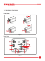
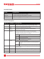
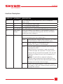
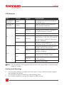
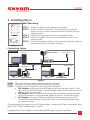
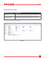
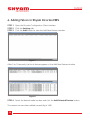
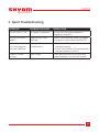
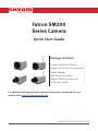
NETWORKS
Falcon SM200
Series Camera
Quick Start Guide
Package Contents
Camera with Mount Base
1
Flexible Clamp with Fixing Screws1
Power Adapter
1
Wall Mounting Screws
1
Terminal Block for Alarm I/O
1
Quick Start Guide
1
For advanced settings and more detailed information, download the user
manual from www.shyamnetworks.com.
www.shyamnetworks.com
SM200
NETWORKS
1. Hardware Overview
Front View
3
2
2
SM201
SM241W
3
1
1
2
2
SM202
SM242W
Figure 1
Rear View
15
4
14
5
13
10
11
12
6
7
8
9
Figure 2
3
SM200
NETWORKS
Available Models
MODEL
DESCRIPTION
SM201
CS mount wired (PoE) and HD camera
SM241W
CS mount wired (PoE) and wireless HD camera
SM202
4x Zoom wired (PoE) and HD camera
SM242 W
4x Zoom wired (PoE) and wireless HD camera
Interface Description
LABEL NO. INTERFACE
DESCRIPTION
1
Microphone
Built-in microphone present on the front panel, which
records sound. Used to capture audio from the vicinity.
2
Lens
Camera lens depending on the model.
3
Wi-Fi
Antenna
To boost the signal of the camera’s wireless network
depending on the model.
4
RS 485
RS-485 is a communication protocol that allows serial
connection between devices. In Falcon, pins listed below can
be used to connect external PTZ module.
First Pin Not used.
5
Audio
D(N)
Indicates data negative.
D(P)
Indicates data positive.
GND
Indicates ground for reference.
Provides audio input and output.
OUT
To connect external speaker for providing audio as
output.
IN
To connect external microphone for capturing audio.
6
Rst.
Used only for service and debug purposes. User should not
use this switch.
7
12V DC
DC inlet to provide an external power supply.
8
LAN Port
One Ethernet port providing connection through Cat5e cable.
9
LEDs
Indicates the working status of the camera.
4
SM200
NETWORKS
Interface Description
LABEL NO. INTERFACE
DESCRIPTION
10
Y (CVBS)
Y in component video mode and CVBS in composite
video mode.
11
Pb
Pb in component video mode.
12
Pr
Pr in component video mode.
13
SD Card Slot
For inserting the SD card to store data directly in to the card.
14
User Input
Button
Boots the camera with default IP configuration. Keep it
pressed for 15 seconds during power on (Sts. LED blinks
amber) and then release it.
15
I/O
Connects an external alarm event detector to input port
and an activation port from output port.
GND
Digital ground is used as return path for 3.3V supply
pin and reference GND for IN and OUT ports.
IN
Active: Input pin is connected to GND.
Inactive: Pin is open or unconnected.
OUT
Uses an open-collector transistor with the emitter
connected to GND.
When the port is activated, it gets connected
to GND through the transistor. The sink current
through the port should not exceed 150 mA and
maximum voltage the port can be exposed to is
24 V DC.
iNote: If used with an external inductive
load like relay, appropriate free-wheeling diode
should be used across the inductive load to avoid
damage to transistor due to surges.
3.3V
Powers auxiliary equipment. Maximum current it
can supply is 200 mA. Drawing more current can
damage the camera.
5
SM200
NETWORKS
LED Behavior
LED
COLOR
STATUS
DESCRIPTION
Top Left on
LAN Port
Green
On
The network to which the camera is
connected is up.
Top Right on
LAN Port
Yellow
On
Indicates network activity and that
data is being transferred.
On
Indicates camera is booting up.
Blinking
Indicates failed firmware upgrade or
no valid firmware in camera.
On
Indicates normal operation.
Blinking
Indicates Ethernet link is down or User
Input Button is ‘On’ (for >15 second).
During reboot it blinks till User Input
Button is released.
Off
Indicates normal operation if
configured to be ‘Off’ from the GUI.
On
Indicates acceptable connection to a
wireless (Wi-Fi or 3G) network.
Blinking
Indicates network activity and data
transfer in progress.
On
Indicates no wireless or 3G network
connection (in wireless mode).
Blinking
Indicates scanning for wireless (Wi-Fi
or 3G) networks.
Off
Indicates wired mode.
Red
Green
Sts.
Amber
Green
Wi-Fi
Red
iNote: The Sts. and Wi-Fi LEDs together blink red when the camera finds no valid firmware image in the flash.
Caution and Warnings
•
Use the power adapter included with the product. Using a different power adapter
may damage the product.
The camera should be installed at a clean and dry place.
For outdoor installation, encase the camera in IP66 housing.
•
•
6
SM200
NETWORKS
2. Installing Falcon
Mounting Hole
42 mm
Figure 3
Wall Mounting
STEP 1 STEP 2 STEP 3 STEP 4 STEP 5 Ensure all cable lines are securely connected.
Drill four holes into the wall. Then hammer the supplied plastic anchors into the holes and secure the plate with the supplied screws.
Fix the wall mount bracket with the supplied screw.
Adjust the angle of the wall mount bracket to aim at the shooting area.
Secure the network camera to the wall/ceiling by the supplied camera stand which has been supplied.
Connecting Falcon
PoE Switch
Falcon Camera
Computer
Power Supply
Switch
PoE Adapter
PoE Adapter
DC Adapter
Power Supply
Power Supply
Computer
Falcon Camera
Computer
Falcon Camera
Figure 4
STEP 1 Place the camera on a flat surface or mount it on a wall.
STEP 2 Optionally, connect external input/output alarm devices.
STEP 3 Connect power, using one of the methods listed below:
• PoE Adapter: Insert one end of an Ethernet cable into the port in the PC and
other end into the PoE adapter. Connect another cable from the PoE port on the
adapter to the camera’s port.
• PoE Switch: Insert one end of an Ethernet cable into the PoE switch and other
end into the camera. Connect another cable from the PC into the PoE switch.
• DC Adapter: Connect an Ethernet cable from the camera’s port into the PC.
Connect the power adaptor cord into the back of the camera and then plug it
into a power source.
On powering-up the camera the Sts. LED glows green. In case any LED does not operate, then
refer to the “Quick Troubleshooting” section.
Congratulations! The installation of the Falcon SM200 series camera is complete.
7
SM200
NETWORKS
3. Configuring Falcon
STEP 1 Power-up the camera.
STEP 2 Configure the PC connected to the camera with IP address between 192.168.1.1 to 192.168.1.254, except the camera IP address 192.168.1.168 and subnet mask to 255.255.255.0.
iNote: If assigning the IP address fails, check that there is no firewall blocking the operation.
STEP 3 Type the http://192.168.1.168 URL in the Internet Explorer 6.0 or above version to access the web interface.
STEP 4 Provide username as admin and password as password to view the Live View page.
Figure 5
Please refer to “Falcon SM200 Series Camera Configuration and User Guide” for more details.
8
SM200
NETWORKS
Accessing Falcon by UPnP
WINDOWS VERSION
PROCEDURE
ME or XP
When enabled on your computer, Falcon is automatically
detected and added to ‘My Network Places’.
Vista or Windows 7
When enabled on your computer, Falcon is automatically
detected and added to ‘Network’.
The camera icon as it appears in Windows 7:
Figure 6
9
SM200
NETWORKS
4. Adding Falcon in Shyam Dicortex VMS
STEP 1 Open the Dicortex Configuration Client interface.
STEP 2 Click the Settings tab.
STEP 3 Click the Add button to view the Add New Devices window.
Figure 7
After 5 to 10 seconds, the list of devices appears in the Add New Devices window.
Figure 8
STEP 4 Select the desired model number and click the Add Selected Devices button.
The camera has now been added successfully to VMS.
10
SM200
NETWORKS
5. Quick Troubleshooting
PROBLEM
PROBABLE REASON
RESOLUTION
The Sts. LED is ‘Off’.
No power is supplied.
Ensure that the power adapter is
plugged in properly.
The Sts. LED blinks
amber.
Ethernet link is not
working.
Check if the Ethernet cable is plugged
in properly to the camera and the PC.
Unable to view the
Live View page on
the user interface.
Improper IP
configuration.
• Ensure that Ethernet cable is
inserted properly.
• Check that network (IP) configuration
is done properly in the PC.
Video is unclear
or hazy.
Lens is dirty.
Clean the lens with a soft cloth and
properly tighten it to the lens mount.
11
SM200
NETWORKS
Warranty
This warranty is valid upto 12 months from the date of purchase.
Any manufacturing defect will be repaired by the company free of charge within the period of
warranty subject to the following conditions:
1.This warranty card must be duly filled in, stamped & signed by the dealer. The card and the
relevant cash memo must be preserved & produced along with the defective unit.
2.Once the defective unit is repaired during the said warranty period, the warranty shall thereafter
continue only for the unexpired period to the original warranty.
3.This warranty is not valid in case of
• Damage resulting from accidents, mishandling, negligence, tampering, unauthorized repair,
failure to follow instructions, lightning, fire and act of God.
• Items not purchased from Authorized Dealers of the Company.
• Batteries (including rechargeable).
• Damage to the tamper proof seal.
• Adaptors (wherever applicable), where the Warranty is valid only up to 6 months from the date
of purchase of the product.
4.In case of a problem with your unit, please contact Customer Care. In the event that you are
advised to send and collect the unit from the Service Center of the Company – the same will be
done at your expense.
5.While Company or its Authorized Service Dealer will make every effort to carry out repairs under
this warranty as soon as possible, it is expressly made clear that the company shall not be held
liable for any direct or indirect loss to user due to delay in providing this service.
6.This warranty excludes every condition/warranty/liability not expressly set out therein.
7.Claims, if any to this warranty shall be subject to the courts having jurisdiction in Delhi, India.
Product ______________________________________________________________________
Model No. _______________________________ Serial No. ___________________________
Dealer’s Stamp & Signature
Customer Care,
Shyam Networks (A Division of Vihaan Networks Ltd.)
21-B, Sec-18, Udyog Vihar, Gurgaon-122015
Haryana, India
Email: [email protected]
All India Helpline No. - +91 124 309 2000 Ext. 2009,
+91 9873573710
Manufactured by Vihaan Networks Ltd. Gurgaon, Haryana, India
12
109.00024.00
SN/QS/SM200/09/11/R1.1