1
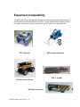
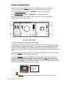
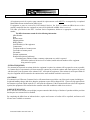
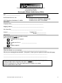
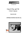
Design and Manufacture of Video Pipeline Inspection Systems
A Full Service Company
www.rstechserv.com
Omni II Pan and Tilt
Color Camera
M
Mooddeell 1100--11662200
OPERATIONS MANUAL
Made in USA
IMPORTANT SAFETY NOTICE
Fire Safety Conditional Approvals
A fire safety conditional approval must be issued by an appropriate licensed electrical
engineer for use of this sewer camera in areas of a sewer that have been demonstrated by
testing and monitoring not to fall under the “Fire Safety Approval” requirement in
Section 2540.2 of Title 8 of the California Code of Regulations. Testing and monitoring
will be considered by the California Division of Occupational Safety and Health, to be
sufficient for this purpose if all measurements indicate that the sewer atmosphere is
below 10% of the lower explosive limit (LEL) and if the user meets all of the following
additional conditions:
(1) Before each use, inspects cable and electrical equipment for damage or wear that
could compromise safety;
(2) Test operates the sewer camera and associated electrical equipment in a dry
location away from any potential exposure to hazardous conditions to determine whether
the equipment functions normally and without any problems, such as sparking, loose
connections, or other similar safety problems;
(3) Tests for the existence of a hazardous atmosphere prior to opening any sewer
access point using a multi-gas tester, and before energizing the equipment, conducts a test
of the sewer atmosphere at the access point estimated to be closest to the end point of the
camera work;
(4) Provides continuous monitoring in the alarm mode at the access point from which
the work is performed at all times while the sewer inspection camera is energized in the
sewer;
(5) De-energizes all electrical equipment and uses mechanical ventilation of a
measurement exceeding 10% of the LEL is obtained;
and Discontinues use of all electrical equipment if the sewer environment cannot be
maintained below 10%.
Copyright © 2002 RS Technical Services
Document Number 900-20571 Rev. A
2
Table of Contents
PAGE 4
Product Overview
PAGE 5
Operator and Equipment Safety
PAGE 6
Equipment Compatibility
PAGE 7
Camera Operation
PAGE 10
Maintenance
PAGE 12
Warranty Policy
PAGE 13
MRA Merchandise Return Authorization
Document Number 900-20571 Rev. A
3
Product Overview
The R.S.T. OMNI EYE II Camera is a pan and tilt color camera designed to be transported by
the mainline tractor (or skidded) and powered by R.S. Technical Services single conductor
(sincon) and multi conductor cable. The compact camera is adaptable for use in sanitary sewer,
storm sewer, and fresh water pipelines with diameters of 6” to 24”. The camera transmits video
and other transducer signals through the sincon cable to the Controller Power Supply. The
Functions of the Omni Eye II color camera are controlled by an auxiliary control box or hand
held control box and the Controller Power Supply.
For optimum performance, The camera must be clean and properly maintained.
Operate transport with the flow.
The pipe should be clean as possible.
Water flow should be minimal.
Due to some uniquely challenging locations, it may be necessary to operate in difficult
situations, which can reduce the efficiency of the equipment.
Document Number 900-20571 Rev. A
4
Operator and Equipment Safety
CAUTION: NEVER HOOK UP OR DISCONNECT EQUIPMENT WITH
POWER TURNED ON!
It is important to be familiar with operations, maintenance, and safety issues
when working with RST equipment.
Read the entire manual before operating the equipment.
The Inspection System requires a steady supply of 120VAC to operate properly.
Before starting of the generator or connecting shore power, make sure that ALL
equipment has been turned OFF. Turn down the controls for camera power and
cable reel speed. After all equipment has been checked, connect the shore
power cord.
If a generator is to be used, allow the generator to warm up for a few minutes.
Note: Diesel generators use a different control panel that is separate from the
controller power supply. Refer to the appropriate generator operator’s manual for
starting.
To prevent personal injury or damage to equipment, turn off Camera power.
When making electrical connections, width adjustments and when maintaining
the tractor or camera, disconnect all power to the control station before servicing.
Caution: Before turning on equipment, plug the Auxiliary Control
Box into the Auxiliary Control jack on the controller power supply.
Caution: Route cords away from traffic or wet areas to avoid tripping on
power cords.
Inspect all transport, camera, lighting cables, and bridles before and after each
use. Replace any broken, worn or frayed bridles or cables.
Always use care when near an open manhole, and when climbing in or out of a
TV inspection vehicle. The tractor and camera assembly can be placed into the
pipeline without personnel entering the manhole. Use proper lifting ropes,
cranes and winches for lifting equipment in/out of pipes.
Document Number 900-20571 Rev. A
5
Equipment Compatibility
The RST Omni Eye II color camera is designed for use with a mainline vehicle mounted
systems as well as Portable Mainline systems. This pan and tilt camera requires the use
of a power control unit, auxiliary controls box, skid or a tractor unit, and cable reel.
RST Cable Reel
RST Portable Cable Reel
RST 8” Crawler
RST Storm Drain Tractor
RST Main Line Tractor
Document Number 900-20571 Rev. A
6
Camera Operation
Ensure that the Camera ON/OFF switch is in the OFF position before connecting
camera to tractor unit, or auxiliary control box to the Controller Power Supply.
Set the LIGHT INTENSITY control to “MINIMUM” or full counter clockwise.
Set the REEL SPEED control to the ‘MINIMUM” or full counter clockwise.
When power is applied to the controller power supply the Frequency and Voltage
indicators will be in the normal range.
POWER
FREQUENCY
REEL
CAMERA
A.C. VOLTAGE
MAX.
VIDEO LEVEL
LOAD AMPS
3
HIGH
2
NORMAL
1
LOW
0
LOAD
VOLTS
0
LINE
AMPS
HIGH
START
MIN.
SPEED
NEUTRAL
LOW
STOP
ON
FOCUS
IRIS
RESET
ON
OUT
OFF
IN
AUX.
INPUT
OFF
R.S. TECHNICAL SERVICES INC.
Controller Power Supply
1. Camera control on the Controller Power Supply
The adjustable camera power supply provides a nominal 120V DC to the camera, transporter
and other down-hole inspection equipment. This section has video processing circuitry which
extracts the video transmitted by the under ground camera into a NTSC video format. Also
incorporated in to the controller is an audio microphone preamplifier, which provides audio for a
VCR.
The Camera ON/OFF switch controls the camera power supply. Above the switch is a green
LED to indicate that the camera power supply is on.
The Camera POWER control knob adjusts the output Voltage of the power supply. Zoom
cameras have a non-adjustable light source. The Camera power only adjusts speed of the
transporter unit. Increase Camera power control knob until a red bar appears on the screen.
Decrease Camera power knob until red bar just leaves the screen. The transporter speed will
not increase after red bar limit appears on the screen.
OVER-VOLTAGE
INDICATOR BAR
SHOWN ON A
MONITOR
SCREEN
Caution: Do not operate equipment with the over limit red bar on screen.
Document Number 900-20571 Rev. A
7
AUX. INPUT jack controls the external camera and transporter by means of auxiliary
control box.
The VIDEO LEVEL LEDS indicate the present of a camera video signal. Depending on
the light in the pipe, the yellow or the green LED is lit. If the RED LED or NO LED is lit,
this indicates a video problem.
The LOAD VOLTS / LINE AMPS is an operation indicator that can be toggled to show
the relative output voltage or current from camera power supply.
The momentary FOCUS and IRIS are used to change the remote camera focus or iris.
The flashing red RESET LED indicates that the power supply was overloaded and the
power supply is disconnected from the output connector. To reset, place the camera
ON/OFF switch to the OFF position. Turn the camera LIGHT control to minimum and
wait about 45 seconds to allow the power supplies to discharge. Then place the Camera
ON/OFF to the ON position. If the RESET LED is flashing, place the camera ON/OFF to
the OFF position and correct the fault.
2. Dual Function Auxiliary Control Box
With the power OFF, plug the Dual Function Control Box into the front panel jack marked
AUX. INPUT (controller power supply). To operate the Omni II Zoom or Omni III Zoom
camera, push the rocker mode switch (on the top of the box), for desired mode STD. or
Zoom. To use standard functions, push toggle switch towards STD (red). Use the 16
standard functions. These common functions are used for the tractor, the pan and rotate
camera as well as tele and wide. Every function change will cause a corresponding flash
of the green transmit LED, in the middle of the control box. To switch between Standard
function controls and Zoom, push down rocker switch on top of the box towards the
Zoom (blue). Use the 16 functions. Commonly, the standard (STD) mode function
buttons are primarily used and the Zoom mode is only used when manually controlling
the Iris, Shutter, Gain, focus etc. The Home button gives the operator the ability to
return the camera to the start (home) location.
Document Number 900-20571 Rev. A
8
Auxiliary Control Box
TRACTOR
TRACTOR
High
Medium
green
Free Whl. LED
TRACTOR
Low
Pan Left
Pan RT
CCW
CW
reverse
Stop
hold 3 sec.
freewheel
IRIS
Iris Cl.
Home
STORM DRAIN TRACTOR CONTROLS
Iris Op.
FOCUS
Foc. In
Foc. Out
Button function:
Pan Lft
Pan Rt.
CCW
CW
Home/lights
(camera)
(camera)
(camera)
(camera)
(camera)
pan left
pan right
counter clockwise rotation
clock wise rotation
rotates camera to home
Lower toggle switch functions:
`
Iris Cl.
Iris Op.
Focus in
Focus out
(camera)
(camera)
(camera)
(camera)
closes camera iris
open camera iris
adjust near focus
adjust far focus
*Standard pan and rotate cameras
Document Number 900-20571 Rev. A
9
Maintenance
Each time the Zoom camera is removed from the pipeline, wash the entire assembly.
Inspect camera cradle and hardware.
Inspect camera lens for scratches and cracks.
Turn camera on and check light bulbs.
Inspect the camera clamps, fins, skids and, mounting hardware.
Inspect the power cable and watertight connections for damage.
Inspect the bridle, clamps, skids, rails, and mounting hardware.
Document Number 900-20571 Rev. A
10
Document Number 900-20571 Rev. A
11
Design and Manufacture of Video Pipeline Inspection Systems
A Full Service Company
SALES SERVICE PARTS
LIMITED WARRANTY POLICY
R.S. Technical Services, Inc. (RST) warrants all items of our manufacture for defects in materials and / or workmanship for
one (1) years from date of receipt by the Customer.
(unless otherwise stated)
This policy is limited to items manufactured by RST. i.e. Camera, Reels, Controllers, Data Displays, Winches and Tractor
Transport Vehicles.
In the event of any malfunction of failure of the equipment, the customer is required to request authorization from RST to
return defective parts or components by calling the RST toll-free number1-800-767-1974 and requesting a MRA
number. (see Figs. 1 & 1A for an example of the form.)
The returned parts or components shall include a packing list, part identity, and the reason for the return of the part.
Freight costs are the responsibility of the Customer unless otherwise agreed to by RST.
All in warranty equipment in need of repair shall be shipped to:
R.S.Technical Services, Inc.
1327 Clegg St.
Petaluma, CA 94954
or
R.S.Technical Service, Inc
292 Midland Trail
Mt. Sterling, KY 40353
RST shall at our option, repair or replace any defective part or component in our service facility, or ship the customer a
replacement component or part.
The customer shall return the defective part or component within ten (10) working days after receipt of the replacement for
credit.
Not covered by this policy are expendable or wear-out items i.e. light bulbs, drive belts, cable connectors.
The generator, monitors, VCRs and air conditioner shall be covered by the Manufacturer’s warranty and any services shall
be referred to each Manufacturer’s service organization.
No warranty shall be applicable to malfunctions due to damage, neglect, wear, misuse, or improper handling or repairs to any
part of the equipment.
Improper repairs are deemed to be repairs made by persons other than factory authorized personnel or repairs not made in
accordance with and covered by the manufacturer’s service manuals, or repairs utilizing parts or materials not equal to those
furnished by the manufacturer.
NOTE: Any un-authorized repairs of any RST equipment will invalidate the warranty.
The responsibility of R.S.Technical Services is set forth above.
RST shall not be liable for any consequential or incidental damages to persons or property resulting from use of or any
breach of warranty expressed or implied, to this (these) products.
Document Number 900-20571 Rev. A
12
MERCHANDISE RETURN AUTHORIZATION (MRA) POLICY
All equipment sent in for repair or parts returned for replacement or credit MUST be accompanied by a completed
Merchandise Return Authorization (MRA) form.
If equipment or parts are received by R.S.Technical Services, Inc. (R.S.T.), without an MRA form or with a
partially completed form, the equipment or parts will be held until an MRA form is received.
Call either your Dealer or the R.S.T. Customer Service Department, whichever is appropriate, to obtain an MRA
number.
The MRA form must contain all of the following information:
MRA Number
Date
Business name
Shipping address
Billing address
Serial Number(s) of the equipment
Contact name
Telephone number of contact person
Fax number of contact person
PO number
Estimate requirements
Detailed description of problem(s)
If returning parts, indicate whether a warranty replacement or a credit is expected.
Provide the number of the invoice to be credited, model and serial numbers of the equipment
being sent in for repairs.
ESTIMATE REQUIRED
If a customer has requested an estimate before the equipment is repaired, an estimate will be prepared as soon as possible.
A Customer Service representative will then contact the customer to provide the estimate and obtain approval to proceed
with the repair. Upon acceptance of the estimate, R.S.T. will repair the equipment. If the estimate is not accepted within 30
days, the equipment will be returned to the customer in the same condition in which it was received.
COD TERMS
If a customer is on COD terms, Customer Service will contact them to provide the cost of the repair or parts (including tax,
freight and handling charges) and advise them the equipment or parts will be shipped COD. Upon receiving approval from
the customer to proceed with the repair, R.S.T. will repair the equipment. If the customer decides not to have the equipment
repaired, the equipment will be returned to the customer in the same condition in which it was received.
PARTS RETURN POLICY
R.S.T. will issue a full refund, (except freight), on parts returned within 90-days of the date of purchase with the provision
that the parts were returned in new condition.
By completing the MRA form as indicated above, repairs and issuance of credits will be expedited, and loaners will
become more available to customers.
Document Number 900-20571 Rev. A
13
Design and Manufacture of Video Pipeline Inspection Systems
A Full Service Company
SALES SERVICE PARTS
THE FOLLOWING FORM IS PROVIDED FOR YOUR CONVENIENCE
MAKE COPIES OF THE FORM FOR YOUR USE.
FILL OUT THE FORM COMPLETELY AND OBTAIN AN MRA NUMBER
MAKE A COPY OF THE COMPLETED FORM FOR YOUR RECORDS
INCLUDE THE ORIGINAL WITH THE EQUIPMENT OR PART (S) THAT ARE BEING RETURNED.
Document Number 900-20571 Rev. A
14
Design and Manufacture of Video Pipeline Inspection Systems
A Full Service Company
SALES SERVICE PARTS
Merchandise Return Authorization (MRA)
Date ___________________________
MRA #
R.S.Technical Services, Inc.
1327 Clegg Street, Petaluma, CA 94954
SECTION I
Customer Service Telephone: 1.800.801.1199
Customer Service Fax: 1.707.769.8806
Company Name_________________________________________________________
Shipping Address_________________________________________________________
City, State, Zip_________________________________________________________
Contact: ____________________________________
Telephone No:_________________
Fax No:_________________
SECTION II
If your merchandise IS NOT covered by warranty,
please check the appropriate box.
Expedite, no P.O. required
OR
Expedite, use P. O. #: ___________________________
OR
Estimate required
Serial number(s) ________________________________________________________________________
SECTION III
What merchandise are you returning?_____________________________________________
______________________________________________________________________________
Why are you returning this merchandise? (Be specific. If more space is required, use the back of this page)
______________________________________________________________________________
______________________________________________________________________________
______________________________________________________________________________
All merchandise sent in for repair, replacement or credit MUST be accompanied by a completed MRA form
including the MRA number assigned by either R.S.T. or your Dealer.
If you are returning parts for credit, please indicate the invoice number to be credited.
This will expedite issuance of the credit.
Document Number 900-20571 Rev. A
15