1
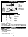
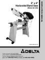
(Model 20-330)
PART NO. 902126 05-31-05
Copyright © 2005 Delta Machinery
To learn more about DELTA MACHINERY
visit our website at: www.deltamachinery.com.
For Parts, Service, Warranty or other Assistance,
please call
1-800-223-7278 (In Canada call 1-800-463-3582).
INSTRUCTION MANUAL
5" x 6"
Horizontal Band Saw
TABLE OF CONTENTS
IMPORTANT SAFETY INSTRUCTIONS . . . . . . . . . . . . . . . . . . . . . . . . . . . . . . . . . . . . . . . . . . . . . . . . . . . . . . . . . . .2
SAFETY GUIDELINES . . . . . . . . . . . . . . . . . . . . . . . . . . . . . . . . . . . . . . . . . . . . . . . . . . . . . . . . . . . . . . . . . . . . . . . .3
GENERAL SAFETY RULES . . . . . . . . . . . . . . . . . . . . . . . . . . . . . . . . . . . . . . . . . . . . . . . . . . . . . . . . . . . . . . . . . . . .4
ADDITIONAL SPECIFIC SAFETY RULES . . . . . . . . . . . . . . . . . . . . . . . . . . . . . . . . . . . . . . . . . . . . . . . . . . . . . . . . .5
FUNCTIONAL DESCRIPTION . . . . . . . . . . . . . . . . . . . . . . . . . . . . . . . . . . . . . . . . . . . . . . . . . . . . . . . . . . . . . . . . . .7
CARTON CONTENTS . . . . . . . . . . . . . . . . . . . . . . . . . . . . . . . . . . . . . . . . . . . . . . . . . . . . . . . . . . . . . . . . . . . . . . . . .8
ASSEMBLY . . . . . . . . . . . . . . . . . . . . . . . . . . . . . . . . . . . . . . . . . . . . . . . . . . . . . . . . . . . . . . . . . . . . . . . . . . . . . . . . .8
OPERATION . . . . . . . . . . . . . . . . . . . . . . . . . . . . . . . . . . . . . . . . . . . . . . . . . . . . . . . . . . . . . . . . . . . . . . . . . . . . . . .11
TROUBLESHOOTING . . . . . . . . . . . . . . . . . . . . . . . . . . . . . . . . . . . . . . . . . . . . . . . . . . . . . . . . . . . . . . . . . . . . . . .19
MAINTENANCE . . . . . . . . . . . . . . . . . . . . . . . . . . . . . . . . . . . . . . . . . . . . . . . . . . . . . . . . . . . . . . . . . . . . . . . . . . . . .22
SERVICE . . . . . . . . . . . . . . . . . . . . . . . . . . . . . . . . . . . . . . . . . . . . . . . . . . . . . . . . . . . . . . . . . . . . . . . . . . . . . . . . . .23
ACCESSORIES . . . . . . . . . . . . . . . . . . . . . . . . . . . . . . . . . . . . . . . . . . . . . . . . . . . . . . . . . . . . . . . . . . . . . . . . . . . .23
WARRANTY . . . . . . . . . . . . . . . . . . . . . . . . . . . . . . . . . . . . . . . . . . . . . . . . . . . . . . . . . . . . . . . . . . . . . . . . . . . . . . . .23
SERVICE CENTER LOCATIONS . . . . . . . . . . . . . . . . . . . . . . . . . . . . . . . . . . . . . . . . . . . . . . . . . . . . . . . .back cover
IMPORTANT SAFETY INSTRUCTIONS
Read and understand all warnings and operating instructions before using any tool or equipment. When
using tools or equipment, basic safety precautions should always be followed to reduce the risk of personal injury.
Improper operation, maintenance or modification of tools or equipment could result in serious injury and property
damage. There are certain applications for which tools and equipment are designed. Delta Machinery strongly
recommends that this product NOT be modified and/or used for any application other than for which it was designed.
If you have any questions relative to its application DO NOT use the product until you have written Delta Machinery
and we have advised you.
Online contact form at www.deltamachinery.com
Postal Mail: Technical Service Manager
Delta Machinery
4825 Highway 45 North
Jackson, TN 38305
(IN CANADA: 125 Mural St. Suite 300, Richmond Hill, ON, L4B 1M4)
Information regarding the safe and proper operation of this tool is available from the following sources:
Power Tool Institute
1300 Sumner Avenue, Cleveland, OH 44115-2851
www.powertoolinstitute.org
National Safety Council
1121 Spring Lake Drive, Itasca, IL 60143-3201
American National Standards Institute, 25 West 43rd Street, 4 floor, New York, NY 10036 www.ansi.org
ANSI 01.1Safety Requirements for Woodworking Machines, and
the U.S. Department of Labor regulations www.osha.gov
SAVE THESE INSTRUCTIONS!
2
SAFETY GUIDELINES - DEFINITIONS
It is important for you to read and understand this manual. The information it contains relates to protecting YOUR
SAFETY and PREVENTING PROBLEMS. The symbols below are used to help you recognize this information.
Indicates an imminently hazardous situation which, if not avoided, will result in death or serious injury.
Indicates a potentially hazardous situation which, if not avoided, could result in death or serious injury.
Indicates a potentially hazardous situation which, if not avoided, may result in minor or moderate injury.
Used without the safety alert symbol indicates potentially hazardous situation which, if not avoided, may
result in property damage.
CALIFORNIA PROPOSITION 65
SOME DUST CREATED BY POWER SANDING, SAWING, GRINDING, DRILLING, AND OTHER
CONSTRUCTION ACTIVITIES contains chemicals known to cause cancer, birth defects or other reproductive harm.
Some examples of these chemicals are:
· lead from lead-based paints,
· crystalline silica from bricks and cement and other masonry products, and
· arsenic and chromium from chemically-treated lumber.
Your risk from these exposures varies, depending on how often you do this type of work. To reduce your exposure to
these chemicals: work in a well ventilated area, and work with approved safety equipment, always wear NIOSH/OSHA
approved, properly fitting face mask or respirator when using such tools.
3
GENERAL SAFETY RULES
READ AND UNDERSTAND ALL WARNINGS AND OPERATING INSTRUCTIONS BEFORE
USING THIS EQUIPMENT. Failure to follow all instructions listed below, may result in electric shock,
fire, and/or serious personal injury or property damage.
IMPORTANT SAFETY INSTRUCTIONS
1. FOR YOUR OWN SAFETY, READ THE INSTRUCTION
MANUAL BEFORE OPERATING THE MACHINE.
Learning the machine’s application, limitations, and
specific hazards will greatly minimize the possibility of
accidents and injury.
14.
2. WEAR EYE AND HEARING PROTECTION.
ALWAYS USE SAFETY GLASSES. Everyday
eyeglasses are NOT safety glasses. USE CERTIFIED
SAFETY EQUIPMENT. Eye protection equipment
should comply with ANSI Z87.1 standards. Hearing
equipment should comply with ANSI S3.19
standards.
15.
3. WEAR PROPER APPAREL. Do not wear loose
clothing, gloves, neckties, rings, bracelets, or other
jewelry which may get caught in moving parts. Nonslip
footwear is recommended. Wear protective hair
covering to contain long hair.
4. DO NOT USE THE MACHINE IN A DANGEROUS
ENVIRONMENT. The use of power tools in damp or
wet locations or in rain can cause shock or
electrocution. Keep your work area well-lit to prevent
tripping or placing arms, hands, and fingers in danger.
5. MAINTAIN ALL TOOLS AND MACHINES IN PEAK
CONDITION. Keep tools sharp and clean for best and safest
performance. Follow instructions for lubricating and changing
accessories. Poorly maintained tools and machines can further
damage the tool or machine and/or cause injury.
6. CHECK FOR DAMAGED PARTS. Before using the
machine, check for any damaged parts. Check for
alignment of moving parts, binding of moving parts,
breakage of parts, and any other conditions that may
affect its operation. A guard or any other part that is
damaged should be properly repaired or replaced.
Damaged parts can cause further damage to the
machine and/or injury.
7. KEEP THE WORK AREA CLEAN. Cluttered areas and
benches invite accidents.
8. KEEP CHILDREN AND VISITORS AWAY. Your shop is a
potentially dangerous environment. Children and visitors can
be injured.
9. REDUCE THE RISK OF UNINTENTIONAL STARTING.
Make sure that the switch is in the “OFF” position
before plugging in the power cord. In the event of a
power failure, move the switch to the “OFF” position.
An accidental start-up can cause injury.
10. USE THE GUARDS. Check to see that all guards are
16.
17.
18.
19.
20.
21.
22.
23.
24.
in place, secured, and working correctly to reduce
the risk of injury.
11. REMOVE ADJUSTING KEYS AND WRENCHES
BEFORE STARTING THE MACHINE. Tools, scrap
pieces, and other debris can be thrown at high speed,
causing injury.
12. USE THE RIGHT MACHINE. Don’t force a machine or
an attachment to do a job for which it was not
designed. Damage to the machine and/or injury may
result.
13. USE RECOMMENDED ACCESSORIES. The use of
accessories and attachments not recommended by
4
Delta may cause damage to the machine or injury to the
user.
USE THE PROPER EXTENSION CORD. Make sure
your extension cord is in good condition. When using
an extension cord, be sure to use one heavy enough to
carry the current your product will draw. An undersized
cord will cause a drop in line voltage, resulting in loss of
power and overheating. See the Extension Cord Chart
for the correct size depending on the cord length and
nameplate ampere rating. If in doubt, use the next
heavier gauge. The smaller the gauge number, the
heavier the cord.
SECURE THE WORKPIECE. Use clamps or a vise to hold
the workpiece when practical. Loss of control of a
workpiece can cause injury.
FEED THE WORKPIECE AGAINST THE DIRECTION OF
THE ROTATION OF THE BLADE, CUTTER, OR ABRASIVE
SURFACE. Feeding it from the other direction will cause
the workpiece to be thrown out at high speed.
DON’T FORCE THE WORKPIECE ON THE MACHINE.
Damage to the machine and/or injury may result.
DON’T OVERREACH. Loss of balance can make you
fall into a working machine, causing injury.
NEVER STAND ON THE MACHINE. Injury could occur if the
tool tips, or if you accidentally contact the cutting tool.
NEVER LEAVE THE MACHINE RUNNING UNATTENDED.
TURN THE POWER OFF. Don’t leave the machine until it
comes to a complete stop. A child or visitor could be injured.
TURN THE MACHINE “OFF”, AND DISCONNECT THE
MACHINE FROM THE POWER SOURCE before installing
or removing accessories, before adjusting or changing
set-ups, or when making repairs. An accidental start-up
can cause injury.
MAKE YOUR WORKSHOP CHILDPROOF WITH
PADLOCKS, MASTER SWITCHES, OR BY
REMOVING STARTER KEYS. The accidental start-up
of a machine by a child or visitor could cause injury.
STAY ALERT, WATCH WHAT YOU ARE DOING, AND
USE COMMON SENSE. DO NOT USE THE
MACHINE WHEN YOU ARE TIRED OR UNDER THE
INFLUENCE OF DRUGS, ALCOHOL, OR MEDICATION. A
moment of inattention while operating power tools may
result in injury.
USE OF THIS TOOL CAN GENERATE
AND DISBURSE DUST OR OTHER AIRBORNE
PARTICLES,
INCLUDING
WOOD
DUST,
CRYSTALLINE SILICA DUST AND ASBESTOS DUST.
Direct particles away from face and body. Always
operate tool in well ventilated area and provide for
proper dust removal. Use dust collection system
wherever possible. Exposure to the dust may cause
serious and permanent respiratory or other injury,
including silicosis (a serious lung disease), cancer, and
death. Avoid breathing the dust, and avoid prolonged
contact with dust. Allowing dust to get into your mouth
or eyes, or lay on your skin may promote absorption of
harmful material. Always use properly fitting
NIOSH/OSHA approved respiratory protection
appropriate for the dust exposure, and wash exposed
areas with soap and water.
ADDITIONAL SPECIFIC SAFETY RULES
FAILURE TO FOLLOW THESE RULES MAY RESULT IN SERIOUS INJURY.
1.
2.
3.
4.
5.
6.
7.
8.
9.
10.
11.
12.
13.
DO NOT OPERATE THIS MACHINE UNTIL it is
assembled and installed according to the
instructions.
OBTAIN ADVICE from your supervisor,
instructor, or another qualified person if you are
not familiar with the operation of this tool.
FOLLOW ALL WIRING CODES and recommended
electrical connections.
USE THE GUARDS WHENEVER POSSIBLE. Check
to see that they are in place, properly adjusted,
secured, and working correctly.
USE PROPER BLADE SIZE and type.
ADJUST THE UPPER BLADE GUIDE so that it is
about 1/8" above the workpiece.
PROPERLY ADJUST the blade tension, tracking,
blade guides, and blade support bearings.
KEEP ARMS, HANDS, AND FINGERS away from
the blade.
AVOID AWKWARD OPERATIONS and hand
positions where a sudden slip could cause a hand
to move into the blade.
NEVER START THE MACHINE before clearing the
table of all objects (tools, scrap pieces, etc.).
NEVER START THE MACHINE with the workpiece
against the blade.
HOLD WORKPIECE FIRMLY against the table. DO
NOT attempt to saw a workpiece that does not have
a flat surface against the table.
HOLD WORKPIECE FIRMLY and feed into blade at
a moderate speed.
14. NEVER REACH UNDER THE TABLE while the
machine is running.
15. TURN THE MACHINE “OFF” to back out of an
uncompleted or jammed cut.
16. MAKE “RELIEF” CUTS prior to cutting long curves.
17. TURN THE MACHINE “OFF” and wait for the blade
to stop prior to cleaning the blade area, removing
debris near the blade, removing or securing
workpiece, or changing the angle of the table. A
coasting blade can be dangerous.
18. NEVER PERFORM LAYOUT, ASSEMBLY, or setup work on the table/work area when the machine is
running.
19. TURN THE MACHINE “OFF” AND DISCONNECT
THE MACHINE from the power source before
installing or removing accessories, before adjusting
or changing set-ups, or when making repairs.
20. TURN THE MACHINE “OFF”, disconnect the
machine from the power source, and clean the
table/work area before leaving the machine. LOCK
THE SWITCH IN THE “OFF” POSITION to prevent
unauthorized use.
21. ADDITIONAL INFORMATION regarding the safe
and proper operation of power tools (i.e. a safety
video) is available from the Power Tool Institute,
1300 Sumner Avenue, Cleveland, OH 44115-2851
(www.powertoolinstitute.com). Information is also
available from the National Safety Council, 1121
Spring Lake Drive, Itasca, IL 60143-3201. Please
refer to the American National Standards Institute
ANSI 01.1 Safety Requirements for Woodworking
Machines and the U.S. Department of Labor OSHA
1910.213 Regulations.
SAVE THESE INSTRUCTIONS. Refer to them often and use
them to instruct others.
5
POWER CONNECTIONS
A separate electrical circuit should be used for your machines. This circuit should not be less than #12 wire and should
be protected with a 20 Amp time lag fuse. If an extension cord is used, use only 3-wire extension cords which have 3prong grounding type plugs and matching receptacle which will accept the machine’s plug. Before connecting the
machine to the power line, make sure the switch (s) is in the “OFF” position and be sure that the electric current is of
the same characteristics as indicated on the machine. All line connections should make good contact. Running on low
voltage will damage the machine.
DO NOT EXPOSE THE MACHINE TO RAIN OR OPERATE THE MACHINE IN DAMP LOCATIONS.
MOTOR SPECIFICATIONS
Your machine is wired for 120 Volts, 60 HZ alternating current. Before connecting the machine to the power source,
make sure the switch is in the “OFF” position.
GROUNDING INSTRUCTIONS
THIS MACHINE MUST BE GROUNDED WHILE IN USE TO PROTECT THE OPERATOR FROM
ELECTRIC SHOCK.
1. All grounded, cord-connected machines:
2. Grounded, cord-connected machines intended for
use on a supply circuit having a nominal rating less
than 150 volts:
In the event of a malfunction or breakdown, grounding
provides a path of least resistance for electric current to
reduce the risk of electric shock. This machine is
equipped with an electric cord having an equipmentgrounding conductor and a grounding plug. The plug must
be plugged into a matching outlet that is properly installed
and grounded in accordance with all local codes and
ordinances.
If the machine is intended for use on a circuit that has an
outlet that looks like the one illustrated in Fig. A, the
machine will have a grounding plug that looks like the plug
illustrated in Fig. A. A temporary adapter, which looks like
the adapter illustrated in Fig. B, may be used to connect
this plug to a matching 2-conductor receptacle as shown
in Fig. B if a properly grounded outlet is not available. The
temporary adapter should be used only until a properly
grounded outlet can be installed by a qualified electrician.
The green-colored rigid ear, lug, and the like, extending
from the adapter must be connected to a permanent
ground such as a properly grounded outlet box. Whenever
the adapter is used, it must be held in place with a metal
screw.
Do not modify the plug provided - if it will not fit the outlet,
have the proper outlet installed by a qualified electrician.
Improper connection of the equipment-grounding
conductor can result in risk of electric shock. The
conductor with insulation having an outer surface that is
green with or without yellow stripes is the equipmentgrounding conductor. If repair or replacement of the
electric cord or plug is necessary, do not connect the
equipment-grounding conductor to a live terminal.
NOTE: In Canada, the use of a temporary adapter is not
permitted by the Canadian Electric Code.
Check with a qualified electrician or service personnel if
t h e g ro u n d i n g i n s t r u c t i o n s a re n o t c o m p l e t e l y
understood, or if in doubt as to whether the machine is
properly grounded.
Use only 3-wire extension cords that have 3-prong
grounding type plugs and matching 3-conductor
receptacles that accept the machine’s plug, as shown in
Fig. A.
IN ALL CASES, MAKE CERTAIN
THE
R E C E P TA C L E I N Q U E S T I O N I S P R O P E R LY
G R O U N D E D . I F Y O U A R E N O T S U R E H AV E A
QUALIFIED ELECTRICIAN CHECK THE RECEPTACLE.
Repair or replace damaged or worn cord immediately.
GROUNDED OUTLET BOX
GROUNDED OUTLET BOX
GROUNDING
MEANS
CURRENT
CARRYING
PRONGS
ADAPTER
GROUNDING BLADE
IS LONGEST OF THE 3 BLADES
Fig. A
6
Fig. B
EXTENSION CORDS
MINIMUM GAUGE EXTENSION CORD
RECOMMENDED SIZES FOR USE WITH STATIONARY ELECTRIC MACHINES
Use proper extension cords. Make sure
your extension cord is in good condition and is a 3-wire
extension cord which has a 3-prong grounding type
plug and matching receptacle which will accept the
machine’s plug. When using an extension cord, be sure
to use one heavy enough to carry the current of the
machine. An undersized cord will cause a drop in line
voltage, resulting in loss of power and overheating. Fig.
D-1 or D-2, shows the correct gauge to use depending
on the cord length. If in doubt, use the next heavier
gauge. The smaller the gauge number, the heavier the
cord.
Ampere
Rating
Volts
Total Length
of Cord in Feet
Gauge of
Extension Cord
0-6
0-6
0-6
0-6
120
120
120
120
up to 25
25-50
50-100
100-150
18 AWG
16 AWG
16 AWG
14 AWG
6-10
6-10
6-10
6-10
120
120
120
120
up to 25
25-50
50-100
100-150
18 AWG
16 AWG
14 AWG
12 AWG
10-12
10-12
10-12
10-12
120
120
120
120
up to 25
25-50
50-100
100-150
16 AWG
16 AWG
14 AWG
12 AWG
12-16
12-16
12-16
120
120
120
up to 25
25-50
14 AWG
12 AWG
GREATER THAN 50 FEET NOT RECOMMENDED
Fig. D-1
FUNCTIONAL DESCRIPTION
FOREWORD
Delta Model 20-330 is a horizontal and vertical, metal-cutting band saw in one. The Delta Model 20-330 has a 1/3 HP
120 volt single phase motor. The cutting capacity is 5” diameter at 90 degrees and 2 7/8” diameter at 45 degrees. For
rectangular shapes, the capacity is 5” X 6” at 90 degrees and 4 1/8” X 2 7/8” at 45 degrees. In the vertical setup, the
capacity is 7 1/2” X 5”. It is an ideal machine for maintenance shops, contractors, metal/plastic fabricators and general
work shops. The Delta Model 20-330 converts to a vertical band saw with standard equipment bracket and work table.
NOTICE: THE PHOTO ON THE MANUAL COVER ILLUSTRATES THE CURRENT PRODUCTION
MODEL. ALL OTHER ILLUSTRATIONS CONTAINED IN THE MANUAL ARE REPRESENTATIVE ONLY
AND MAY NOT DEPICT THE ACTUAL COLOR, LABELING OR ACCESSORIES AND ARE INTENDED
TO ILLUSTRATE TECHNIQUE ONLY.
7
CARTON CONTENTS
Fig. 1A Hardware
1
12
3
5
8
6
9
2
1. Saw unit
2. Legs
3. Shelf
4. Wheel assembly
5. Stock advance stop
6. Stand handle
7. Vertical table
8. Vise clamping handwheel
9. Floor mounting hardware
10. Pulley
11. Table support bracket
12. Pulley guard
11
7
10
4
Fig. 1A
Fig. 1B Hardware
8
1
4
2
3
1. M6x10mm hex head screw
2. 6mm lock washer
3. M6 hex nut
4. 5/16”-18x1”
5. 1/4”-20x1/2”
6. 1/4”-20 hex nut
7. 1/4” flat washer
8. 5/32 hex wrench
9. Cotter pin
10. 5/16” washer
11. 5/16”-18 hex nut
9
5
10
6
11
7
Fig. 1B
UNPACKING AND CLEANING
Carefully unpack the machine and all loose items from the shipping container(s). Remove the protective coating from
all unpainted surfaces. This coating may be removed with a soft cloth moistened with kerosene (do not use acetone,
gasoline or lacquer thinner for this purpose). After cleaning, cover the unpainted surfaces with a good quality household
floor paste wax.
ASSEMBLY
FOR YOUR OWN SAFETY, DO NOT CONNECT THE MACHINE TO THE POWER SOURCE UNTIL
THE MACHINE IS COMPLETELY ASSEMBLED AND YOU READ AND UNDERSTAND THE ENTIRE
INSTRUCTION MANUAL.
ASSEMBLY TOOLS REQUIRED
* 5/32 hex wrench(supplied)
* 10 mm, 12mm and 1/2 inch open end or socket wrenches (not supplied)
ASSEMBLY TIME ESTIMATE - 1 to 2 hours
8
ASSEMBLING STAND
1. Assemble the two legs (A) and (B) Fig. 2, to the band
saw base using the six 5/16-18x1" hex head cap
screws, three of which are shown at (C) Fig. 2, twelve
5/16" flat washers and six 5/16-18" hex nuts. Align the
holes in the band saw with the holes in the legs. Place a
5/16" flat washer onto a 5/16-18x1" hex head cap
screw, insert screw through the hole in the band saw
and the hole in the leg, place a 5/16" flat washer onto
the screw, thread a 5/16" hex nut onto the screw, and
tighten securely. Repeat this process for the five
remaining holes.
C
B
A
C
E
D
Fig. 2
2. Assemble the shelf (D) Fig. 2, to the two legs (A) and
(B). Align the four holes in the shelf (D) with the four
holes in the two legs (A) and (B). Insert a M6x10mm hex
head screw, two of which are shown at (E) through the
hole in the shelf and leg. Place a 6mm lockwasher onto
the screw, thread a M6 hex nut onto the screw, and
tighten securely. Repeat this process for the three
remaining holes.
ASSEMBLING WHEELS
B
Assemble the wheel assembly (A) Fig. 3, to the bottom
of the left leg. Align the holes in the wheel assembly with
the holes in the left leg. Place a 1/4" flat washer onto a
1/4-20x1/2" hex head screw, insert the screw through
the holes (B) in the wheel assembly and the hole in the
left leg, place a 1/4" flat washer onto the screw, thread
a 1/4-20 hex nut onto the screw, and tighten securely.
Repeat this process for the remaining hole.
A
Fig. 3
ASSEMBLING VISE HANDWHEEL
B
A
Assemble the vise clamping handwheel (A) Fig. 4, to the
shaft (B), and tighten set screw (C) against the flat on the
shaft (B).
C
Fig. 4
9
ASSEMBLING STAND HANDLE
B
Insert ends of handle (A) Fig. 5, into the two holes (B) on
the right leg and fasten in place using the two cotter pins
supplied.
A
ASSEMBLING STOCK ADVANCE STOP
Fig. 5
Assemble the stock advance stop assembly (A) to the
hole on the front of the table and tighten the two set
screws (B), as shown in Fig. 6.
ASSEMBLING GUARD AND BELT
A
B
Open the belt and pulley guard (A) Fig. 7, and position
the bottom half of the guard assembly behind the
pulleys (B) as shown. Line up the two holes in the
bottom of the guard with the two threaded holes in the
casting. NOTE: DO NOT COMPLETELY TIGHTEN THE
PULLEY GUARD TO THE CASTING AT THIS TIME.
Place a 1/4" flat washer onto a 1/4-20x1/2" hex head
screw and insert screw through hole in pulley guard and
thread screw into the tapped hole in the casting. Repeat
this process for the remaining hole. Raise the motor and
assemble the belt (D) Fig. 7, to the desired steps of the
two pulleys then release the motor. A speed selection
chart (E) is located on the inside of the guard cover.
When the belt is tensioned, tighten screws (C).
B
Fig. 6
A
E
D
C
B
FASTENING BAND SAW TO
SUPPORTING SURFACE
Fig. 7
IF DURING OPERATION THERE IS ANY
TENDENCY FOR THE BAND SAW TO
TIP OVER, SLIDE OR WALK ON THE SUPPORTING
SURFACE, THE RIGHT LEG OF THE BAND SAW
MUST BE SECURED TO A SUPPORTING SURFACE.
B
Align the hole in the “L” shaped floor mounting bracket
(A) Fig. 8, with the hole in the bottom of the right leg (B).
Insert a 5/16” flat washer (C) onto a 5/16-18x1/2” hex
head screw (D). Insert screw through the floor mounting
bracket (A) and the right leg. Place a 5/16” flat washer
(E) onto the screw (D) and tighten securely. Repeat this
process for the remaining hole on the other side of the
right leg. Then secure the two brakcets to the supporting
surface.
A
F
C
E
D
Fig. 8
10
OPERATION
OPERATIONAL CONTROLS AND ADJUSTMENTS
STARTING AND STOPPING MACHINE
1. The on/off switch (A) Fig. 13 is located on the front
of the band saw. To turn the machine “ON,” move the
switch up to the “ON” position.
2. To turn the machine “OFF”, move the switch (A)
down to the “OFF” position.
B
B
MAKE SURE THAT THE SWITCH IS IN
THE
“OFF”
POSITION
BEFORE
PLUGGING IN THE POWER CORD. IN THE EVENT OF A
POWER FAILURE, MOVE THE SWITCH TO THE “OFF”
POSITION. AN ACCIDENTAL START-UP CAN CAUSE
INJURY.
A
Fig. 13
LOCKING SWITCH IN “OFF” POSITION
IMPORTANT: When the machine is not in use, the
switch should be locked in the “OFF” position to prevent
unauthorized use, using a padlock with a 3/16" diameter
shackle through the holes at (B) FIg. 13.
B
AUTOMATIC SHUT-OFF
A
When the band saw is in the horizontal position, the saw
should shut itself off automatically. After a completed
cut has been made, and the saw is in the down or
horizontal position, the shut-off bracket (B) Fig. 14 will
contact the toggle switch (A) and push it to the down
position, turning off the power. IMPORTANT: THE
SHUT-OFF BRACKET (B) SHOULD NOT REST ON OR
BE SUPPORTED BY THE TOGGLE SWITCH (A).
Fig. 14
D
C
The downward travel of the saw should be adjusted to
just trip the toggle switch at its lowest position. To adjust
the downward travel of the saw arm, loosen lock nut (C)
Fig. 15, and turn the stop screw (D) in or out until the
correct adjustment is made; then tighten lock nut (C).
Fig. 15
A
ADJUSTING BLADE TENSION
DISCONNECT
MACHINE
POWER SOURCE.
FROM
1. Turn blade tension handwheel (A) Fig. 16, clockwise to
increase or counterclockwise to decrease blade tension.
Correct tension is obtained when the blade is just tight
enough that no slippage occurs between the blade and
the wheels.
2. When the machine is not in use, release the blade
tension.
Fig. 16
11
ADJUSTING BLADE TRACKING
C
B
1. Place the saw arm in the vertical position and open
the wheel cover (A) Fig. 17.
A
2. Turn on the band saw. The blade is tracking properly
when the back of the blade (B) Fig. 17, is just touching
the edge of the wheel flange (C). The back of the blade
should not be rubbing against the flange.
3. If an adjustment is necessary the blade guide
bearings and blade support bearings (E) Fig. 19 (two of
which are shown) should be clear of the blade.
Fig. 17
4. Loosen screw (D) Fig. 18.
5. With the band saw running, turn adjusting screw (E)
until the blade is tracking properly making certain blade
tension is maintained by turning blade tension knob. (F).
The blade is tracking properly when the back side of the
saw blade just touches the flange on the wheel.
F
6. Tighten screw (D) Fig. 18, when adjustment is
complete.
7. IMPORTANT: IT IS POSSIBLE WHEN MAKING
THIS ADJUSTMENT TO OVER TIGHTEN THE
ADJUSTING SCREW (E), FIG. 18, AND CAUSE THE
BLADE TO BE MIS-ALIGNED. If this happens, loosen
the adjusting screw (E) several turns but do not remove
it from its threaded hole and loosen screw (D). Turn
screw (D) clock-wise until it stops but do not tighten.
Then turn the adjusting screw (E) clockwise until it
bottoms. Turn on the machine and turn adjusting screw
(E) clockwise a small amount at a time until the blade is
tracking correctly and tighten screw (D) Fig. 18.
D
E
Fig. 18
8. After the blade is tracking properly make sure to adjust the blade guide bearings and blade support
bearings.
ADJUSTING BLADE SUPPORT
BEARINGS
DISCONNECT
MACHINE
POWER SOURCE.
D
FROM
C
A
1. The blade support bearing (A) Fig. 19, should be adjusted so it just touches the back of the saw blade after
the blade is tracking properly. To adjust, loosen screw
(C) and move the bracket (D) up or down until the
support bearing (A) just touches the back of the blade
(B). Then tighten screw (C).
B
E
Fig. 19
2. Adjust the other blade support bearing in the same
manner.
12
ADJUSTING BLADE GUIDE
BEARINGS
E
DISCONNECT
MACHINE
POWER SOURCE.
FROM
D
A
F
1. The blade guide bearings (A) and (B) Fig. 20 should
be adjusted so they just touch the sides of the blade (C)
after the blade is tracking properly and the blade
support bearing has been adjusted. To adjust, proceed
as follows:
C
B
Fig. 20
2. Remove the cover plate that is attached to the face
of the right guide bracket (D) Fig. 20.
3. The inside guide bearing (A) Fig. 20, is mounted to a
fixed shaft and cannot be adjusted. The outside guide
bearing (B) is mounted on an eccentric shaft and should
be adjusted so that the sides of the blade (C) just
contact the guide bearings (A) and (B). To adjust, loosen
nut (E) and turn adjusting nut (F) until proper adjustment
is made. Then tighten nut (E).
4. Adjust the other blade guide bearings in the same
manner.
ADJUSTING BLADE 90 DEGREES TO
THE TABLE SURFACE
A
In order for accurate work to be accomplished on your
saw the blade must be at 90 degrees to the table
surface. To check and adjust, proceed as follows:
DISCONNECT
MACHINE
POWER SOURCE.
B
B
FROM
C
C
1. Lower the saw arm to the horizontal position. Place
a square (A) Fig. 21, on the table with one end of the
square against the blade, as shown.
Fig. 21
2. If the blade is not at 90 degrees to the table, loosen
the two screws (B) Fig. 21, that attach the blade guide
brackets to the guide arms and rotate both guide
brackets (C) until the blade is at 90 degrees to the table.
Then tighten the two screws (B). NOTE: CARE SHOULD
BE TAKEN NOT TO DISTURB THE BLADE GUIDE
SUPPORT BEARINGS WHEN MAKING THIS
ADJUSTMENT.
13
ADJUSTING BLADE GUIDE
BRACKETS
DISCONNECT
MACHINE
POWER SOURCE.
C
A
FROM
The left and right blade guide brackets (A) and (B) Fig.
22, are adjustable by loosening the two lock knobs (C)
and sliding the brackets to accommodate the width of
the work piece. The guide brackets (A) and (B) should be
set as close as possible to the workpiece, without
interfering or touching the workpiece, or contacting the
table. Once the adjustment is made, tighten the lock
knobs (C).
B
C
Fig. 22
ADJUSTING FEED RATE
DISCONNECT
MACHINE
POWER SOURCE.
FROM
The feed rate of the saw arm can be adjusted by turning
the control arm (A) Fig. 23, counterclockwise to increase
or clockwise to decrease the feed rate. Do not turn the
control arm more than one turn at a time. Excessive feed
pressure can break or stall the blade. Insufficient feed
pressure dulls the blade rapidly.
A
Fig. 23
OPERATING AND
ADJUSTING THE VISE
B
A
The workpiece (A) is placed between the vise jaws with
the required amount to be cut-off extending out past the
blade, as shown in Fig. 24. To tighten the workpiece in
the vise, turn handwheel (B).
Fig. 24
The vise can be adjusted to cut any angle from 0
degrees to 45 degrees by loosening the two screws (C)
Fig. 25, and positioning the vise jaw (D) to the desired
angle. A scale (E) is positioned on the rear of the table to
give the proper cutting angle. lt may also be necessary
when angle cutting to move the left vise jaw (F) to the
rear to clear the blade guide bracket.
F
C
E
D
Fig. 25
14
ADJUSTING STOCK STOP
The stock stop is used when more than one piece is to
be cut to the same length. Position the stop block (A)
Fig. 26, the desired distance away from the blade. lt is
good practice to have the work contact the stop at the
bottom of the work, as shown. The stop may be
repositioned in or out by loosening set screw (B) and
moving the stop accordingly. When not using the stock
stop, rotate the stop below the table surface.
B
A
Fig. 26
For cuts when the work will not extend beyond the table,
the stop (C) Fig. 27, can be turned around, as shown, to
contact the workpiece.
C
ARM POSITIONING LEVER
Fig. 27
An arm positioning lever (A) Fig. 28, is supplied on the
front of the base and can be engaged with one of the
two notches (B) depending on the size of the workpiece,
for positioning the arm during set-up. The lever (A)
should be engaged with notch (C) when operating the
saw in the vertical position.
B
C
A
CHANGING SPEEDS AND
ADJUSTING BELT TENSION
Fig. 28
DISCONNECT
MACHINE
FROM
POWER SOURCE BEFORE CHANGING
SPEEDS AND ADJUSTING BELT TENSION.
Proper belt tension is obtained when there is
approximately 1/4" deflection of the belt using light
finger pressure at the center span of the pulleys. To
adjust belt tension, loosen lock nut (C) Fig. 29, and turn
adjusting screw (D) clockwise to increase tension and
counterclockwise to decrease tension. Tighten locknut
(C) Fig. 29, after belt tension is obtained.
C
D
Fig. 29
15
When changing speeds, release belt tension and open
belt and pulley guard cover (D) Fig. 30. Speed rates of
80, 120, and 200 feet per minute are available with your
band saw. When the belt is on the largest step of the
motor pulley (A) Fig. 30, and the smallest step of the
gear box pulley (B) the blade speed will be 200 feet per
minute. When the belt is on the smallest step of the
motor pulley (A) and the largest step of the gear box
pulley (B) the blade speed will be 80 feet per minute.
When changing speeds, first release belt tension. After
the desired speed is obtained, adjust belt tension and
close belt and pulley guard cover (D).
B
D
A
C
Fig. 30
SPEED AND MATERIAL CHART
Fig. 31 illustrates the correct speeds and the position of
the belt on the motor and gear box pulleys for most
common materials cut on the band saw.
BLADE SELECTION
1. Your band saw uses blades 1/2" wide, 64½" long
and .020-.025 thick. Accessory blades with a pitch
(number of teeth per. inch of the blade) of 10 and 14
are available from Delta.
Material To Be Cut
Speed
Tool Steel
Stainless Steel
Alloy Steel
Hard Bronze
Mild Steel
Medium Hard Brass
Medium Hard
Bronze
Soft Brass
Aluminum
Plastic
Other Light
Materials
80 FPM
Belt Position
Motor
Gear
Small
Large
120 FPM
Middle
Middle
200 FPM
Large
Small
Fig. 31
2. Never use a blade so coarse that less than three
consecutive teeth are engaged in the workpiece at one
time. (Too few teeth will cause the teeth to strip out).
3. Never use a blade finer than required to obtain a
satisfactory surface finish or satisfactory flatness (Too
many teeth engaged in the workpiece will prevent
attainment of a satisfactory sawing rate; frequently
produce "dished" cuts or cuts which are neither square
or parallel).
4. When thin rectangular solid bar is to be sawed, the
work should, whenever possible, be loaded with the
thinnest cross section exposed to the blade teeth. The
pitch (number of teeth per. inch of the blade) selected
must provide engagement of at least three consecutive
teeth in the workpiece. Should application of this rule
not be possible because the thinnest cross section is
too thin, the piece must be loaded with the wider
dimension exposed to the saw teeth and a coarser blade
selected.
5. When thin wall pipe or tubing or channel iron are cut,
a 14 pitch (number of teeth per inch) blade is used.
Fewer than 14 teeth per inch will almost never be
satisfactory.For standard wall pipe or tubing 10 teeth per
inch is satisfactory.
16
CHANGING BAND SAW FROM
HORIZONTAL TO VERTICAL
POSITION
Your saw can be changed to the vertical position for
notching, slitting or contour work as follows:
DISCONNECT
MACHINE
POWER SOURCE.
C
B
A
FROM
1. Move the cutting arm to the vertical position and
lock in place with the arm positioning lever (C) Fig. 32.
Stop screw (A) Fig. 32 should bear against base casting
when arm is in the vertical position. If adjustment is
needed loosen lock nut (B) and adjust screw (A).
2. Remove two screws (C) and bearing cover plate (D)
Fig. 33.
3. Assemble the vertical table (E) to the guide bracket
using the two screws (C) that were removed in STEP 2,
as shown in Fig. 34.
4. Assemble one end of the table support bracket (G)
Fig. 35 to the table using a 1/4-20x1/2" flat head screw
and 1/4-20 nut (H) and the other end underneath the
guide bracket lock knob (J), as shown in Fig. 35.
Fig. 32
D
C
C
Fig. 33
C
E
Fig. 34
H
J
G
Fig. 35
17
CHANGING BLADES
DISCONNECT
MACHINE
POWER SOURCE.
B
FROM
A
1. Raise the saw arm to the vertical position and open
the blade wheel cover (A) as shown in Fig. 36.
E
2. Release blade tension by turning blade tension hand
knob (B).
C
3. Remove the two finger guards (C).
F
4. Carefully slip blade (D) off both wheels (E), and guide
assemblies (F).
D
5. Place the new blade between each of the blade
guide bearings (F) and around both wheels (E). NOTE:
THE TEETH MUST BE POINTING DOWN ON THE
RIGHT HAND SIDE AS SHOWN BY THE
DIRECTIONAL ARROW IN FIG. 31.
TEETH
DIRECTION
E
F
C
6. Replace finger guards (C), and adjust blade tension
by turning hand knob (B).
7. Close the blade wheel cover (A).
MACHINE USE
Fig. 36
TYPICAL OPERATIONS FOR HORIZONTAL BAND SAW
The horizontal band saw cuts all types of metals, including ferrous and non-ferrous metal, steel pipe, angle iron,
conduit, brass, aluminum and copper. As shown in Fig. 24 and 25, workpieces can be cut at 90 or tilted to any angle
in the vise.
TYPICAL OPERATIONS FOR VERTICAL BAND SAW
NOTE: THIS BAND SAW IS RECOMMENDED FOR USE IN CUTTING METAL ONLY.
Before starting the machine, see that all adjustments are properly made and the guards are in place. Turn the upper
wheel by hand to make sure that everything is correct BEFORE turning on the power. Keep the top guide within 1/8"
of the work piece at all times. Do not force the material against the blade. Light pressure on the work piece will produce
a smoother cut, and prevent excess friction, heating, and hardening of the blade. KEEP THE SAW BLADE SHARP.
Very little forward pressure is required for normal cutting. Keep the workpiece moving at a slow and consistent rate
against the blade to ensure a smooth and accurate cut. Avoid twisting the blade by trying to turn sharp corners.
Remember, you must saw around corners.
CUTTING CURVES
When cutting curves, turn the workpiece carefully so
that the blade follows without twisting. If a curve is so
abrupt that it is necessary to repeatedly back up and cut
a new kerf, a narrower blade, a blade with more set, or
additional relief cuts Fig. 37, may be necessary to allow
the blade to cut more efficiently. The more set a blade
has, the easier it will allow the stock to be turned, but the
cut is usually rougher than where a medium amount of
set is used.
When withdrawing the piece being cut, changing the
cut, or for any other reason, be careful not to
accidentally draw the blade off the wheels. In most
Fig. 37
cases, it is easier and safer to turn the stock and saw out
through the waste material, rather than try to withdraw
the stock from the blade.
18
TROUBLESHOOTING
For assistance with your machine, visit our website at www.deltamachinery.com for a list of service centers or call
the DELTA Machinery help line at 1-800-223-7278 (In Canada call 1-800-463-3582).
In spite of how well a band saw is maintained, problems can occur. The following troubleshooting guide will help you
solve the more common problems:
Trouble: SAW WILL NOT START.
Probable Cause
Remedy
1. Saw not plugged in.
1. Plug in saw.
2. Fuse blown or circuit breaker tripped.
2. Replace fuse or reset circuit breaker.
3. Cord damaged.
3. Have cord replaced.
Trouble: BREAKER KICKS OUT FREQUENTLY.
Probable Cause
Remedy
1. Extension cord too light or too long.
1. Replace with adequate size cord.
2. Feeding stock too fast.
2. Feed stock more slowly.
3. Blade in poor condition (dull, warped, gummed).
3. Clean or replace blade.
4. Low voltage supply.
4. Contact an electrician.
Trouble: BAND SAW VIBRATES EXCESSIVELY.
Probable Cause
Remedy
1. Machine not mounted securely to stand.
1. Tighten all mounting hardware.
2. Stand on uneven surface.
2. Reposition on flat level surface.
3. Worn belt.
3. Replace belt.
4. Pulley not aligned.
4. Adjust pulleys.
5. Motor not fastened securely.
5. Tighten all mounting hardware.
Trouble: BAND SAW DOES NOT COME UP TO SPEED.
Probable Cause
Remedy
1. Low voltage due to improper extension cord size.
1. Replace with adequate size cord.
2. Low voltage.
2. Contact an electrician.
Trouble: BLADES BREAK.
Probable Cause
Remedy
1. Blade not tensioned properly.
1. Adjust blade tension.
2. Blade guides improperly adjusted.
2. Check and adjust blade guides.
3. Blade support bearing improperly adjusted.
3. Adjust blade support bearing.
4. Blade wheel tracking adjustment improperly set.
4. Check and adjust blade tracking.
5. Bad weld on blade.
5. Replace the blade.
6. Worn tires.
6. Replace tires.
7. Forcing wide blade around short radius.
7. Change to a narrower blade.
8. Dull blade or insufficient set.
8. Replace blade.
9. Upper blade guide set too high.
9. Set upper blade guide within 1/8" of workpiece.
10. Continuous running of machine when not actually
cutting.
10. Turn off machine when not performing cutting
operation.
(continued on next page)
19
Trouble: BLADE WILL NOT TRACK.
Probable Cause
Remedy
1. Blade too loose
1. Adjust tension
2. Upper wheel not properly adjusted.
2. Adjust upper wheel.
3. Improperly adjusted blade support bearing.
3. Adjust blade support bearing.
Trouble: BLADE WILL NOT STAY ON WHEEL.
Probable Cause
Remedy
1. Blade not tensioned properly.
1. Adjust blade tension.
2. Blade guides improperly adjusted.
2. Check and adjust blade guides.
3. Blade support bearing improperly adjusted.
3. Adjust blade support bearing.
4. Blade wheel not tracking properly.
4. Check and adjust blade tracking.
5. Bad weld on blade.
5. Replace the blade.
6. Worn tires.
6. Replace tires.
Trouble: BAND SAW MAKES UNSATISFACTORY CUTS.
Probable Cause
Remedy
1. Blade not tensioned properly.
1. Adjust blade tension.
2. Blade guides improperly adjusted.
2. Check and adjust blade guides.
3. Blade support bearing improperly set.
3. Adjust blade support bearing.
4. Blade wheel not tracking properly.
4. Check and adjust blade tracking.
5. Bad weld on blade.
5. Replace the blade.
6. Worn tires.
6. Replace tires.
7. Incorrect blade for work being done.
7. Change the blade.
8. Dull blade or insufficient set.
8. Replace blade.
9. Upper blade guide set too high.
9. Set upper blade guide within 1/8" of work piece.
20
BAND SAW BLADES
A band saw blade is a delicate piece of steel that is subjected to tremendous strain. You can
obtain long use from a band saw blade if you use it properly. Use blades of proper thickness, width
and temper for the various types of material and cuts.
Any one of a number of conditions may cause a band saw blade to break. Blade breakage is, in
some cases, unavoidable, being the natural result of the peculiar stresses to which blades are
subjected. Blades will break often due to avoidable causes, such as the lack of care to the blade
or the blade not being properly adjusted to the band saw. The most common causes of blade
breakage are:
(1) faulty alignments and adjustments of the guides.
(2) forcing or twisting a wide blade around a curve of short radius.
(3) feeding the work piece too fast into the blade.
(4) dullness of the teeth, or absence of sufficient set.
(5) improperly tensioned blade.
(6) top guide set too high above the work piece being cut.
(7) using a blade with a lumpy or improperly finished braze or weld.
(8) continuous running of the saw blade when not cutting.
Use blades that are 64½" in length on this machine.
Always use a sharp blade. Keep it free from gum and pitch. Clean frequently with a stiff fiber
brush.
A new blade, in most cases, will perform better and last longer than a re-sharpened blade.
Insure that the blade guides are adjusted properly.
Do not force or twist the blade around a curve or a very short radius.
Feed the workpiece through the blade at a consistent rate, allow the blade to do the cutting – do
not feed the work piece too fast.
Do not apply excessive tension to the blade. The tension is only necessary to drive the blade
without slipping on the wheels. Narrow blades require less tension than wider blades.
21
MAINTENANCE
LUBRICATING THE VISE SCREW
B
The vise lead screw should be lubricated using light
machine oil as needed.
A
The drive gears run in an oil bath gear box and it should
not be necessary to change this oil more than once a
year unless the oil becomes contaminated or a leak
occurs due to improper replacement of the gear box
cover. To change oil in the gear box, proceed as follows:
DISCONNECT
MACHINE
POWER SOURCE.
A
FROM
Fig. 38
1. Position cutting arm in the horizontal position.
2. Remove the four screws (A) Fig. 38, and the gear
box cover (B) and gasket.
3. Remove the old oil from inside the gear box and
replace the oil using 140 weight gear oil, available from
Delta. The new oil should just come to the edge (C) Fig.
39, of the gear box. Do not overflow. Replace the
gasket, cover and four screws that were removed in
STEP 3.
C
Fig. 39
KEEP MACHINE CLEAN
Periodically blow out all air passages with dry compressed
air. All plastic parts should be cleaned with a soft damp
cloth. NEVER use solvents to clean plastic parts. They could
possibly dissolve or otherwise damage the material.
WEAR ANSI Z87.1 SAFETY GLASSES
WHILE USING COMPRESSED AIR.
FAILURE TO START
Should your machine fail to start, check to make sure the
prongs on the cord plug are making good contact in the
outlet. Also, check for blown fuses or open circuit breakers
in the line.
LUBRICATION
Apply household floor paste wax to the machine table and
extension table or other work surface weekly.
PROTECTING CAST IRON FROM RUST
To clean and protect cast iron tables from rust, you will
need the following materials: 1 pushblock from a jointer,
1 sheet of medium Scotch-Brite™ Blending Hand Pad, 1
can of WD-40®, 1 can of degreaser, 1 can of TopCote®
Aerosol. Apply the WD-40 and polish the table surface
with the Scotch-Brite pad using the pushblock as a
holddown. Degrease the table, then apply the TopCote®
accordingly.
22
SERVICE
PARTS, SERVICE OR WARRANTY ASSISTANCE
All Delta Machines and accessories are manufactured to high quality standards and are serviced by a network
of Porter-Cable • Delta Factory Service Centers and Delta Authorized Service Stations. To obtain additional
information regarding your Delta quality product or to obtain parts, service, warranty assistance, or the location
of the nearest service outlet, please call 1-800-223-7278 (In Canada call 1-800-463-3582).
ACCESSORIES
A complete line of accessories is available from your Delta Supplier, Porter-Cable • Delta Factory Service Centers,
and Delta Authorized Service Stations. Please visit our Web Site www.deltamachinery.com for a catalog or
for the name of your nearest supplier.
Since accessories other than those offered by Delta have not been tested
with this product, use of such accessories could be hazardous. For safest operation, only
Delta recommended accessories should be used with this product.
WARRANTY
Two Year Limited New Product Warranty
Delta will repair or replace, at its expense and at its option, any new Delta machine, machine part, or machine accessory
which in normal use has proven to be defective in workmanship or material, provided that the customer returns the product
prepaid to a Delta factory service center or authorized service station with proof of purchase of the product within two
years and provides Delta with reasonable opportunity to verify the alleged defect by inspection. For all refurbished Delta
product, the warranty period is 180 days. Delta may require that electric motors be returned prepaid to a motor
manufacturer’s authorized station for inspection and repair or replacement. Delta will not be responsible for any asserted
defect which has resulted from normal wear, misuse, abuse or repair or alteration made or specifically authorized by
anyone other than an authorized Delta service facility or representative. Under no circumstances will Delta be liable for
incidental or consequential damages resulting from defective products. This warranty is Delta’s sole warranty and sets
forth the customer’s exclusive remedy, with respect to defective products; all other warranties, express or implied, whether
of merchantability, fitness for purpose, or otherwise, are expressly disclaimed by Delta.
23
PORTER-CABLE • DELTA SERVICE CENTERS
(CENTROS DE SERVICIO DE PORTER-CABLE • DELTA)
Parts and Repair Service for Porter-Cable • Delta Machinery are Available at These Locations
(Obtenga Refaccion de Partes o Servicio para su Herramienta en los Siguientes Centros de Porter-Cable • Delta)
ARIZONA
Phoenix 85013-2906
4501 N. 7th Ave.
Phone: (602) 279-6414
Fax: (602) 279-5470
CALIFORNIA
Ontario 91761 (Los Angeles)
3949A East Guasti Road
Phone: (909) 390-5555
Fax: (909) 390-5554
San Diego 92111
7290 Clairemont Mesa Blvd.
Phone: (858) 279-2011
Fax: (858) 279-0362
San Leandro 94577 (Oakland)
3039 Teagarden Street
Phone: (510) 357-9762
Fax: (510) 357-7939
COLORADO
Denver 80223
700 West Mississippi Ave.
Phone: (303) 922-8325
Fax: (303) 922-0245
FLORIDA
Davie 33314 (Miami)
4343 South State Rd. 7 (441)
Unit #107
Phone: (954) 321-6635
Fax: (954) 321-6638
Tampa 33634
4909 West Waters Ave.
Phone: (813) 884-0434
Fax: (813) 888-5997
GEORGIA
Forest Park 30297 (Atlanta)
5442 Frontage Road,
Suite 112
Phone: (404) 608-0006
Fax: (404) 608-1123
ILLINOIS
Addison 60101 (Chicago)
400 South Rohlwing Rd.
Phone: (630) 424-8805
Fax: (630) 424-8895
KANSAS
Overland Park 66214
9201 Quivira Road
Phone: (913) 495-4330
Fax: (913) 495-4378
MARYLAND
Elkridge 21075 (Baltimore)
7397-102 Washington Blvd.
Phone: (410) 799-9394
Fax: (410) 799-9398
MASSACHUSETTS
Franklin 02038 (Boston)
Franklin Industrial Park
101E Constitution Blvd.
Phone: (508) 520-8802
Fax: (508) 528-8089
MICHIGAN
Madison Heights 48071 (Detroit)
30475 Stephenson Highway
Phone: (248) 597-5000
Fax: (248) 597-5004
MINNESOTA
Eden Prairie 55344
9709 Valley View Road
Phone: (952) 884-9191
Fax: (952) 884-3750
OREGON
Portland 97230
14811 North East Airport Way
Phone: (503) 255-6556
Fax: (503) 255-6543
MISSOURI
St. Louis 63146
11477 Page Service Drive
Phone: (314) 997-9100
Fax: (314) 997-9183
PENNSYLVANIA
Willow Grove 19090
(Philadelphia)
520 North York Road
Phone: (215) 658-1430
Fax: (215) 658-1433
NEW YORK
Flushing 11365-1595 (N.Y.C.)
175-25 Horace Harding Expwy.
Phone: (718) 225-2040
Fax: (718) 423-9619
NORTH CAROLINA
Charlotte 28270
9129 Monroe Road, Suite 115
Phone: (704) 841-1176
Fax: (704) 708-4625
OHIO
Columbus 43229
1948 Schrock Road
Phone: (614) 895-3112
Fax: (614) 895-3187
Parma Heights OH 44130
6485 Pearl Road
Phone: (440) 842-9100
Fax: (440) 884-3430
TEXAS
Carrollton 75006 (Dallas)
1300 Interstate 35 N, Suite 112
Phone: (972) 446-2996
Fax: (972) 446-8157
Houston 77022-2122
536 East Tidwell Rd.
Phone: (713) 692-7111
Fax: (713) 692-1107
WASHINGTON
Auburn 98001(Seattle)
3320 West Valley HWY, North
Building D, Suite 111
Phone: (253) 333-8353
Fax: (253) 333-9613
Authorized Service Stations are located in many large cities. Telephone 800-438-2486 or 731-541-6042 for assistance locating one.
Parts and accessories for Porter-Cable·Delta products should be obtained by contacting any Porter-Cable·Delta Distributor, Authorized
Service Center, or Porter-Cable·Delta Factory Service Center. If you do not have access to any of these, call 800-223-7278 and you will
be directed to the nearest Porter-Cable·Delta Factory Service Center. Las Estaciones de Servicio Autorizadas están ubicadas en muchas
grandes ciudades. Llame al 800-438-2486 ó al 731-541-6042 para obtener asistencia a fin de localizar una. Las piezas y los accesorios
para los productos Porter-Cable·Delta deben obtenerse poniéndose en contacto con cualquier distribuidor Porter-Cable·Delta, Centro
de Servicio Autorizado o Centro de Servicio de Fábrica Porter-Cable·Delta. Si no tiene acceso a ninguna de estas opciones, llame al
800-223-7278 y le dirigirán al Centro de Servicio de Fábrica Porter-Cable·Delta más cercano.
CANADIAN PORTER-CABLE • DELTA SERVICE CENTERS
ALBERTA
Bay 6, 2520-23rd St. N.E.
Calgary, Alberta
T2E 8L2
Phone: (403) 735-6166
Fax: (403) 735-6144
BRITISH COLUMBIA
8520 Baxter Place
Burnaby, B.C.
V5A 4T8
Phone: (604) 420-0102
Fax: (604) 420-3522
MANITOBA
1699 Dublin Avenue
Winnipeg, Manitoba
R3H 0H2
Phone: (204) 633-9259
Fax: (204) 632-1976
ONTARIO
505 Southgate Drive
Guelph, Ontario
N1H 6M7
Phone: (519) 767-4132
Fax: (519) 767-4131
QUÉBEC
1515 ave.
St-Jean Baptiste, Suite 160
Québec, Québec
G2E 5E2
Phone: (418) 877-7112
Fax: (418) 877-7123
1447, Begin
St-Laurent, (Montréal),
Québec
H4R 1V8
Phone: (514) 336-8772
Fax: (514) 336-3505
The following are trademarks of PORTER-CABLE • DELTA (Las siguientes son marcas registradas de PORTER-CABLE • DELTA S.A.) (Les marques
suivantes sont des marques de fabriquant de la PORTER-CABLE • DELTA): Auto-Set®, BAMMER®, B.O.S.S.®, Builder’s Saw®, Contractor’s Saw®,
Contractor’s Saw II™, Delta®, DELTACRAFT®, DELTAGRAM™, Delta Series 2000™, DURATRONIC™, Emc²™, FLEX®, Flying Chips™, FRAME SAW®,
Grip Vac™, Homecraft®, INNOVATION THAT WORKS®, Jet-Lock®, JETSTREAM®, ‘kickstand®, LASERLOC®, MICRO-SET®, Micro-Set®, MIDI LATHE®,
MORTEN™, NETWORK™, OMNIJIG®, POCKET CUTTER®, PORTA-BAND®, PORTA-PLANE®, PORTER-CABLE®&(design), PORTERCABLE®PROFESSIONAL POWER TOOLS, PORTER-CABLE REDEFINING PERFORMANCE™, Posi-Matic®, Q-3®&(design), QUICKSAND®&(design),
QUICKSET™, QUICKSET II®, QUICKSET PLUS™, RIPTIDE™&(design), SAFE GUARD II®, SAFE-LOC®, Sanding Center®, SANDTRAP®&(design), SAW
BOSS®, Sawbuck™, Sidekick®, SPEED-BLOC®, SPEEDMATIC®, SPEEDTRONIC®, STAIR EASE®, The American Woodshop®&(design), The Lumber
Company®&(design), THE PROFESSIONAL EDGE®, THE PROFESSIONAL SELECT®, THIN-LINE™, TIGER®, TIGER CUB®, TIGER SAW®,
TORQBUSTER®, TORQ-BUSTER®, TRU-MATCH™, TWIN-LITE®, UNIGUARD®, Unifence®, UNIFEEDER™, Unihead®, Uniplane™, Unirip®, Unisaw®,
Univise®, Versa-Feeder®, VERSA-PLANE® , WHISPER SERIES®, WOODWORKER’S CHOICE™.
Trademarks noted with ™ and ® are registered in the United States Patent and Trademark Office and may also be registered in other countries. Las
Marcas Registradas con el signo de ™ y ® son registradas por la Oficina de Registros y Patentes de los Estados Unidos y también pueden estar
registradas en otros países.
PC7.2-0105-149