1
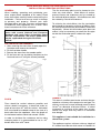
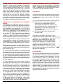
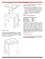
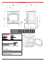
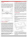
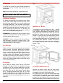
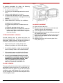
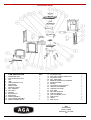
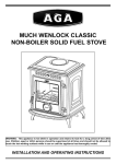
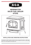
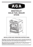
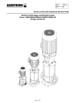
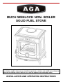
MUCH WENLOCK NON- BOILER
SOLID FUEL STOVE
WARNING:
This appliance is hot while in operation and retains its heat for a long period of time after
use. Children, aged or infirm persons should be supervised at all times and should not be allowed to
touch the hot working surfaces while in use or until the appliance has thoroughly cooled.
INSTALLATION AND OPERATING INSTRUCTIONS
TABLE OF CONTENTS
PAGE NO.
1.
General
. . . . . . . . . . . . . . . . . . . . . . . . . . . . . . . . . . . . . . . . . . . . . . . . . . . . . . . . . . . . . .
3
2.
Pre-Installation Assembly . . . . . . . . . . . . . . . . . . . . . . . . . . . . . . . . . . . . . . . . . . . . . . . . .
3
3.
Flues
. . . . . . . . . . . . . . . . . . . . . . . . . . . . . . . . . . . . . . . . . . . . . . . . . . . . . . . . . . . . . . . .
3
4.
Chimney . . . . . . . . . . . . . . . . . . . . . . . . . . . . . . . . . . . . . . . . . . . . . . . . . . . . . . . . . . . . . .
3
5.
Ventilation & Combustion Air Requirements . . . . . . . . . . . . . . . . . . . . . . . . . . . . . . . . . .
4
6.
Flue Pipes . . . . . . . . . . . . . . . . . . . . . . . . . . . . . . . . . . . . . . . . . . . . . . . . . . . . . . . . . . . .
4
7.
Top Flue Exit . . . . . . . . . . . . . . . . . . . . . . . . . . . . . . . . . . . . . . . . . . . . . . . . . . . . . . . . . .
4
8.
Rear Flue Exit . . . . . . . . . . . . . . . . . . . . . . . . . . . . . . . . . . . . . . . . . . . . . . . . . . . . . . . . .
5
9.
Location . . . . . . . . . . . . . . . . . . . . . . . . . . . . . . . . . . . . . . . . . . . . . . . . . . . . . . . . . . . . . .
5
10.
Installation Clearances . . . . . . . . . . . . . . . . . . . . . . . . . . . . . . . . . . . . . . . . . . . . . . . . . . .
5
11.
Floor Protection . . . . . . . . . . . . . . . . . . . . . . . . . . . . . . . . . . . . . . . . . . . . . . . . . . . . . . . .
5
12.
Specification . . . . . . . . . . . . . . . . . . . . . . . . . . . . . . . . . . . . . . . . . . . . . . . . . . . . . . . . . . .
6
13.
Lighting. . . . . . . . . . . . . . . . . . . . . . . . . . . . . . . . . . . . . . . . . . . . . . . . . . . . . . . . . . . . . . .
7
14.
Important Notes . . . . . . . . . . . . . . . . . . . . . . . . . . . . . . . . . . . . . . . . . . . . . . . . . . . . . . . .
8
15.
Operating Instructions . . . . . . . . . . . . . . . . . . . . . . . . . . . . . . . . . . . . . . . . . . . . . . . . . . .
9
16.
Primary Air Settings . . . . . . . . . . . . . . . . . . . . . . . . . . . . . . . . . . . . . . . . . . . . . . . . . . . . .
9
17.
Recommended Fuels . . . . . . . . . . . . . . . . . . . . . . . . . . . . . . . . . . . . . . . . . . . . . . . . . . . .
9
18.
Air Wash Settings. . . . . . . . . . . . . . . . . . . . . . . . . . . . . . . . . . . . . . . . . . . . . . . . . . . . . . .
9
19.
Tertiary Air/System Control
9
20.
Operation . . . . . . . . . . . . . . . . . . . . . . . . . . . . . . . . . . . . . . . . . . . . . . . . . . . . . . . . . . . . .
10
21.
Overnight Burning . . . . . . . . . . . . . . . . . . . . . . . . . . . . . . . . . . . . . . . . . . . . . . . . . . . . . .
10
22.
Re-Fuelling . . . . . . . . . . . . . . . . . . . . . . . . . . . . . . . . . . . . . . . . . . . . . . . . . . . . . . . . . . . .
10
23.
De-Ashing
10
24.
Disposal of Ashes
. . . . . . . . . . . . . . . . . . . . . . . . . . . . . . . . . . . . . . . . . . . . . . . . . . . . . .
10
25.
To Clean Chimney Outlet . . . . . . . . . . . . . . . . . . . . . . . . . . . . . . . . . . . . . . . . . . . . . . . . .
10
26.
Fire Safety . . . . . . . . . . . . . . . . . . . . . . . . . . . . . . . . . . . . . . . . . . . . . . . . . . . . . . . . . . . .
11
27.
Vitreous Enamel Cleaning . . . . . . . . . . . . . . . . . . . . . . . . . . . . . . . . . . . . . . . . . . . . . . . .
11
28.
Glass Cleaning . . . . . . . . . . . . . . . . . . . . . . . . . . . . . . . . . . . . . . . . . . . . . . . . . . . . . . . . .
11
29.
Glass Replacement . . . . . . . . . . . . . . . . . . . . . . . . . . . . . . . . . . . . . . . . . . . . . . . . . . . . .
11
30.
Exploded View . . . . . . . . . . . . . . . . . . . . . . . . . . . . . . . . . . . . . . . . . . . . . . . . . . . . . . . . .
12
. . . . . . . . . . . . . . . . . . . . . . . . . . . . . . . . . . . . . . . . . . . . . . .
. . . . . . . . . . . . . . . . . . . . . . . . . . . . . . . . . . . . . . . . . . . . . . . . . . . . . . . . . . . .
2
MUCH WENLOCK SOLID FUEL NON BOILER STOVE
INSTALLATION & OPERATING INSTRUCTIONS
GENERAL
When
installing,
operating
and
maintaining
The flue termination point must be located to min-
your
imise
stove respect basic standards of fire safety. Read
these instructions carefully before commencing the
installation.
persons
and
to
determine
property.
Consult
your
local
regulations
are
in
force.
Save
these instructions for future reference.
The
installation
dance
with
must
current
be
completed
National
and
in
To
the
requirements
and
these
Wind
effects
of
suction,
Wind effects can also
minimise
the
wind
effects,
the
flue
termination
point should be located a minimum of 600mm from
the roof measured vertically and 2300mm measured
horizontally.
accor-
Where this termination point does not
suffice it may be necessary to extend the flue pipe
European
so that the termination point is above the apex.
Standards and Local Codes. It should be noted
that
effects.
be created by natural land contours.
Municipal office and your insurance representative
what
wind
the roof and adjacent objects.
Failure to do so may result in damage
to
any
pressure zones and turbulence can be created by
publications
2300
Fig 2
may be superseded during the life of this
manual.
600
PRE INSTALLATION ASSEMBLY
1. After removing the stove from its pack,open the
front door and remove the contents.
2. Fit the front door handle.
3. Remove the stove from the wooden pallet.
4. Fit the front ash tray by slotting into place on the
front and secure it using the screws provided.
Fig.1
Appliance
CHIMNEY
FLUES
Flues
This stove is a radiant room heater and must be con-
should
be
vertical
wherever
possible
nected to a chimney of the proper size and type.The
and
chimney must have a cross-sectional area of at least
where a bend is necessary, it should not make an
angle of more than 45
o
with the vertical.
2
181cm
Horizontal
less draught.
the horizontal section should not exceed 150mm.
to
minimise
flue
resistance
and
to
This appliance is not suitable for installation in a
make
shared flue system.
o
sweeping easier it is recommended to use 2 x 45
o
bends rather than a 90
It is best
nection to a larger size may result in a somewhat
back outlet from the appliance, when the length of
order
or a diameter of at least 150mm.
to connect to a chimney of the same size, as con-
flue runs should be avoided except in the case of a
In
Soot Door
bend.
The appliance requires minimum chimney height of
4.5 metres from floor on which stove is installed. An
3
existing masonry chimney should be sound and if
using air in operation at full rate, (i.e. extraction fans,
mason.
closed.
necessary inspected and repaired by a competent
It
may
be
necessary
to
line
the
using a suitable stainless steel flue liner.
tumble dryers) with all external doors and windows
chimney
The stove
If spillage occurs following the above oper-
ation, an additional air vent of sufficient size to pre-
must be connected to a chimney with a minimum
vent this occurrence should be installed.
continuous draught of 12 Pascal’s to obtain nominal
output. Poor draught conditions will result in poor
FLUE PIPES
chimney
A flue pipe should only be used to connect an appli-
stove performance.
at
the
Allowing for an access into the
lower
end
will
facilitate
cleaning.
Chimneys for use with solid fuel appliances should
ance to a chimney and should not pass through any
be capable of withstanding a temperature of 1100°C
without
any
structural
change
which
would
the stability or performance of the chimney.
VENTILATION
&
MENTS
COMBUSTION
AIR
roof space.
impair
(a)
REQUIRE-
This appliance is rated at less than 6kW.
(b)
It is imper-
effective
2
cm .
es
to
air
Regulations.
requirement
for
this
The
S31,316 S33, or the equivalent Euronorm 88-
minimum
appliance
is
5.5
(c)
If a draught stabiliser is used then this increas23.5
2
requirement
equation:
cm .
for
When
this
calculating
appliance
combustion
use
the
air
following
a total free area of at least 550mm
2
least 1mm and as described in BS EN
Grade 316 S11, 316 S13, 316 S16, 316
to this appliance must comply with B.S. 8303: Part 1
Building
Stainless steel with a wall thickness of at
heat resisting steel plate, sheet and strip, for
order to support correct combustion. The air supply
current
Cast iron as described in BS 41: 1973 (1981), or
10095:1999 Specification for stainless and
ative that there is sufficient air supply to the stove in
and
Flue pipes may be of any of the follow-
ing materials:
71 designation, or
Vitreous enamelled steel complying with
BS 6999: 1989.
Flue
per
kW of rated output above 5kW shall be provided.
pipes
with
spigot
and
socket
joints
should be fitted with the socket upper most.
Clearance
If same or adjacent room, it will be necessary to cal-
to
combustibles
must
be
adhered to when fitting the flue pipe. The
culate additional air supply. All materials used in the
flue gas mass flow is 4.56 g/s mineral fuel
manufacture of air vents should be such that the
and 4.11 g/s wood logs. The mean flue gas
vent is dimensionally stable and corrosion resistant.
temperature
directly
downstream
of
the
spigot at nominal heat output is 275 °C. The
The effective free area of any vent should be ascer-
tained before installation. The effect of any screen
appliance is suitable for continuous opera-
free area of any vent.
operation on wood logs.
tion
should be allowed for when determining the effective
Air vents direct to the outside of the building should
pass through normally occupied areas of the room.
than
the
dimensions
specified
within
cavity
walls
should
include
a
using
fitted
in
the
room
or
unscrewing
plate
from
the
top
Remove
the
two
Next remove the
of
the
stove
by
Connect the
using approved fire cement ensuring that no cement
blocks the flue passageway.
adjacent
rooms where this appliance is fitted, additional air
vents will be required to alleviate the possibility of
spillage of products of combustion from the appli-
ance/flue while the fan is in operation.
blanking
by
socket at the top of the stove and cement into place
Existing air vents should be
If there is an air extraction fan or other
appliance
flue
plate
connector pipe (not supplied) into the top flue outlet
of the correct size and unobstructed for the appliair
blanking
Replace the hob in the correct position.
Joints between air
vents and outside walls should be sealed to prevent
ance in use.
hob
plate to the rear flue outlet at the back of the stove.
be installed in such a manner as not to impair the
the ingress of moisture.
the
unscrewing the two screws, connect this blanking
continuous duct across the cavity. The duct should
weather resistance of the cavity.
intermittent
screws from underneath the hob.
Building Regulations.
traversing
and
it on the floor, taking care not to damage it.
nal. These air vents must also be fire proofed as per
vents
fuel
top of the stove, turn the hob upside down and place
the
Building Regulations from any part of any flue termi-
Air
mineral
For top outlet configuration remove the hob from the
An air vent outside the building should not be locatless
solid
TOP FLUE EXIT
be located so that any air current produced will not
ed
on
Where such
an installation exists, a test for spillage should be
made with the fan or fans and other appliances
4
LOCATION
Fig3
There
are
several
conditions
to
be
selecting a location for your stove.
considered
in
a. Position in the area to be heated, central loca-
tions are usually best. If situated in an alcove, site
as far forward as possible to provide more heat to
the room. For non-combustible surfaces, allow a
minimum air gap to the rear, sides and top of
100mm for air to flow around the appliance.
b. Allowances for proper clearances to combustibles.
INSTALLATION CLEARANCES
Clearance to combustible materials
From the front -
900mm
From the sides -
600mm
From the flue pipe -
600mm
From the back -
700mm
The connector may pass through walls or partitions
constructed of combustible materials provided the
connector is either listed for wall pass-through or is
routed
through
a
device
listed
for
a
wall
pass-
through and is installed in accordance with the conditions of the listing. Any unexposed metal that is
used
as
part
of
a
wall
pass-through
system
is
exposed to flue gases shall be constructed of stain-
less steel or other equivalent material that will resist
REAR FLUE EXIT
corrosion,
For rear flue outlet configuration push in flue con-
nector pipe (not supplied) into flue outlet socket at
fire
cement
ensuring
blocks the flue passageway.
that
no
or
cracking
from
flue
gas
at
FLOOR PROTECTION
the rear of the stove and cement into place using
approved
softening,
temperatures up to 982°C.
cement
It is recommended that this appliance is installed on
a solid, level non-combustible hearth conforming to
current Building Regulations.
Fig. 4
5
SPECIFICATION
Fig5
G
Dimensions
A
Metric (mm)
700
Imperial (inches)
SPECIFICATIONS
Flue Outlet
4
27 /8
B
542
3
21 /8
METRIC
320 x 210mm
Log Size
300mm
Gross Weight
137 KG
TECHNICAL DATA
Nominal Output Wood Logs
Solid Mineral Fuel
Non Boiler
5.5 kW
4.1 kW
Typical refuelling intervals to obtain nominal
outputs:
1.5 hours wood
4 hours solid mineral fuel
WARNING:
AIR
SUPPLY
DO
TO
5
10 /8
Fig.6
150mm
Fire Door Size
C
271
NOT
THE
FRONT OF THE STOVE.
OBSTRUCT
SPIN
PRIMARY
VALVE
AT
THE
6
D
165
4
6 /8
E
423
5
16 /8
F
476
6
18 /8
G
530
20
7
/8
LIGHTING
1.
Before lighting the stove, ensure that any build up of ashes in the fire
2.
Open the firebox and cover the grate with crumpled pieces of paper.
3.
Lay pieces of kindling on top of the paper towards the back of the fire
4.
Open the primary air inlet by turning the spin valve at the front of the
5.
Open the secondary air control by sliding the control knob located over
6.
Ignite the paper and close the firedoor.
7.
When the kindling is well alight, open the fire door and add more
box has been removed and that the ashpan has been emptied.
box.
stove anticlockwise. (See Fig.7).
the top of the fire door to the left (See Fig.7a).
kindling of a larger size to sustain the fire.
Close the firedoor.
operate this appliance with the firedoor open.
8.
Do not
Never use inflammable liquid i.e. gasoline, petrol paraffin etc. to start
or freshen up a fire in this heater.
9.
When a hot bed of fuel is established, add the normal fuel and adjust
10.
When re-fuelling open the firedoor and reload, close the firedoor.
11.
To shut the fire down, do not add fuel, make sure that the firedoor is
the spin valve to the required setting.
properly closed and that the primary secondary and tertiary air
controls are all in the closed position. Cutting off the air supply will
reduce the heat output.
This appliance is hot whilst in operation.
Keep children, clothing and furniture a safe distance away.
7
IMPORTANT NOTES
Now that your AGA Solid Fuel Stove is installed and no doubt you are looking forward to many
comforts it will provide, we would like to give you some tips on how to get the best results from
your stove.
1.
We would like if you could take some time to read the operating instructions/hints, which we are
2.
Do not burn fuel with a high moisture content, such as a damp peat or unseasoned timber.
3.
Clean the flue-ways of the stove regularly and ensure that there are no blockages. Check flue
4.
Before loading fresh fuel into the firebox, riddle fully to remove all ashes, this will allow better and
5.
Never allow a build up of ashes in the ash pan, as this will cause the grate to burn out prema-
confident, will be of great benefit to you.
This will only result in a build up of tar in the stove and in the chimney.
ways before lighting especially after a shut down period.
cleaner burning. See Re-Fuelling Section Page 10.
turely.
6.
Avoid slow burning of damp or unseasoned fuel as this will result in tarring flue ways and chim-
7.
Allow adequate air ventilation to ensure plenty of air for combustion.
8.
Do not use as an incinerator burning rubbish/household waste.
9.
Do not leave fire door open for long periods as this will over heat the unit causing unnecessary
10.
Clean the chimney at least twice a year.
11.
Burning soft fuels such as timber and peat will stain the glass.
ney i.e. peat or timber.
damage.
manent staining.
Regular cleaning will prevent per-
12.
Keep all combustible materials a safe distance away from unit, please see Installation Clearances
13.
For safety reasons never leave children or the elderly unaccompanied while stove is in use.
14.
15.
Page 5.
a fire guard.
Use
Avoid contact with the appliance when in use as stove reaches very high operating tempera-
tures.
This appliance should be regularly maintained by a competent service engineer.
Use only
replacement parts recommended by AGA. Making unauthorised modifications, or using unauthorised parts will invalidate your guarantee and may cause damage or injury.
8
OPERATING INSTRUCTIONS
RECOMMENDED FUELS
CAUTION!
This
“Never
use
gasoline”
gasoline
type
lantern
fuel
fuel,
is
hot
whilst
in
operation.
Keep
(Ancit)
for
closed
tested
using
appliances,
300mm long are suitable.
such liquid well away from the heater at all times.
heater
been
able and may give similar results.
Keep all
Operate stove only with fuelling door closed.
has
seasoned
sized
between
20g and 140g. Other fuels are commercially avail-
kerosene, charcoal lighter fluid or similar liquids to
start or ‘freshen up’ a fire in this heater.
appliance
wood logs and manufactured briquetted smokeless
Wood logs up to
All fuels should be stored
under cover and kept as dry as possible prior to use.
This
Do not use fuels with a coke ingredient as this may
children,
cause
clothing and furniture a safe distance away.
the
Reduced
Fig.7
calorific
grate
outputs
values
to
will
are
overheat,
result
used.
causing
when
Never
fuels
use
damage.
of
lower
gasoline
or
gasoline type lantern fuel, kerosene, charcoal lighter
fluid or similar liquids to start or freshen up a fire in
this heater.
Keep all such liquid well away from the
heater at all times.
Operate the stove only with the
fuelling door closed except for re-fuelling.
AIR WASH SETTINGS
The following settings should be observed for the
Air Wash Shutter (Fig. 8) when burning the specified
fuels.
Note: This part can become very hot. Always use
the operating tool when opening and closing the Air
Fig.7a
Wash Shutter.
OPEN
When
burning
house
coal,
timber
or
peat.
Using this control when burning these fuels will help
to keep the glass clean.
CLOSE When burning anthracite and manufactured
smokeless fuels.
PRIMARY AIR SETTINGS
Fig 8
The spin valve (Part No. 33), located at the bottom
end of the door, controls the primary air supply to the
stove.
For
maximum
heat
output
and
burn
rate
rotate the spin valve (Part No. 33) fully in an anti-
clockwise direction and for a minimum heat output
and burn rate rotate the spin valve clockwise until
fully closed. For nominal heat output the spin wheel
needs to be open between 1 – 2 turns. You will soon
learn
the
spin
valve
settings
to
best
suit
your
requirements. When burning wood logs the primary
air control should be closed and the secondary air
wash should be used to control the rate of burn.
Opening
the
slider
use
air
control
less
than
halfway
enough to obtain nominal output.
this
when
should
be
It is important to
burning
manufactured
TERTIARY AIR / SYSTEM CONTROL
smokeless fuels. The air passing over the grate will
help to cool it and will prevent premature failure.
IMPORTANT: The first few fires should be
relatively
small
to
permit
the
refractory
properly and to season the stove.
The stove has a Tertiary Air System located at the
top, under the roof baffle and connected to an air
to
feed ducting on the right hand side and controlled by
set
a push pull slider assembly, located at the bottom
right hand side.
9
OPERATION
Fig.9
To operate the Tertiary Air, push to open and pull to
close. Open tertiary air slider only when the fire is
established.
Note: Close off the tertiary air for overnight burn.
WARNING:
THE
AIR
SLIDER
IS
HOT
WHILE
STOVE IS IN USE - USE TOOL TO OPERATE.
OVERNIGHT BURNING
To achieve an overnight or a slow burn rate, close
the Air Wash Shutter fully, close the front spin valve
fully then open about half a turn, or less, depending
on draught conditions.
If the fuel load is too small or
the draught too strong the spin valve may need to be
DISPOSAL OF ASHES
closed even further to sustain the low burn rate. This
will
be
found
by
trial
and
error
by
adjusting
the
The ashpan must be emptied every day.
amount of air depending upon the amount of fuel left
are allowed to build up to grate level the fire box
over at the end of the burning period.
insert could be damaged by overheating. We recommend that you remove ashes after you have rid-
REMEMBER: Coal gases are toxic so ensure there
dled the fire.
is sufficient draught to take the flue gasses up the
er
Instructions
outlined
above
with
a
rial,
may
fitting
lid.
The
closed
container
of
pending final disposal. If ashes are buried in
soil, or otherwise dumped they should be retained in
result in carbon monoxide entering the house rather
the
than being drawn up the chimney.
closed
cooled.
RE-FUELLING
tight
ashes should be placed on a non-combustible mate-
WARNING: Failure to comply with the Installation
Operating
Ashes can be very hot and should be
placed in a metal or other non-combustible contain-
chimney and not into the room.
and
If ashes
container
Fig.10
until
they
are
thoroughly
Fig. 10
Riddle the fire by connecting the grate operating tool
onto
the
rocker
connection
located
at
the
bottom
front of the stove, then gently pull and push the rock-
er arm until all dead ash has fallen through into the
ashpan.
Before
opening
the
door,
open
the
spin
valve by turning it anti-clockwise, as this will help to
eliminate any smoke or fly ash resident in the combustion chamber. Add fuel to the fire, taking care not
to over fill. Close fire door and re-set the spin valve
to the required setting.
DE-ASHING
Never allow the ashpan to over fill as it will cause
damage to the grate. When ash build-up becomes
TO CLEAN CHIMNEY OUTLET
excessive in the fire chamber riddle the fire until all
dead ash has fallen through to the ashpan. Open the
Remove
front door (Part No.14) and remove ashpan (Part
the
back
bricks
and
the
side
bricks.
Remove the fire fence (3 off) and lift the baffle from
No.11) using the operating tool (Part No.1). Close
its supports, then move it forward to clear
the front door (Part No. 14). When the ash is dis-
the support at the rear. Drop rear of baffle and rotate
posed of, replace the empty ashpan. Do not leave
it until the baffle is upside down on top of the firebed.
this appliance with the loading door open even for a
Lift one side of the baffle to allow it to be removed
short time.
through
the
front
opening.
Ensure
the
tertiary
air
pipe is sealed to the right hand side with fire cement.
10
FIRE SAFETY
Fig 11
To
provide
reasonable
fire
safety,
1.
Do not over fire the stove.
the
following
should be given serious consideration.
2.
3.
4.
5.
6.
Over-firing will also damage painted or enamel
finish.
Install a smoke detector in the room.
A conveniently located class A fire extinguisher
to contend with small fires resulting from burning
embers.
A practical evacuation plan.
A plan to deal with a chimney fire as follows:(a) Notify the fire department.
GLASS REPLACEMENT
(b) Prepare occupants for immediate evacuation.
(a)
(c) Close all openings into the stove.
(b)
(d) While awaiting the fire department watch for
ignition to adjacent combustibles from over
(c)
heated stove pipe or from embers or sparks
(d)
from the chimney.
(e)
VITREOUS ENAMEL CLEANING
General
cleaning
must
stove is thoroughly cool.
be
carried
out
when
(f)
the
(g)
If this stove is finished in a
high gloss vitreous enamel, to keep the enamel in
the best condition observe the following tips:
1.
Wipe over daily with a soapy damp cloth,
2.
For stubborn deposits a soap impregnated pad
3.
Only products recommended by the Vitreous
4.
followed by a polish with a clean dry duster.
can be carefully used on the vitreous enamel.
Enamel Association, carry the Vitramel label.
DO NOT USE ABRASIVE PADS OR OVEN
CLEANSERS CONTAINING CITRIC ACID ON
ENAMELLED SURFACES. ENSURE THAT
THE CLEANSER MANUFACTURERS
INSTRUCTIONS ARE ADHERED TO.
GLASS CLEANING
The glass will self clean when there is sufficient heat
generated by the burning fuel. If a build-up of cre-
osote occurs on the glass it may be due to draught
conditions, poor quality damp fuel or very low burn-
ing for a long time. It is best to clean the glass when
it is thoroughly cooled.
11
Open the front door fully.
Remove the four corner screws and clips and
carefully remove the broken glass.
Clean the glass recess in the door.
Attach adhesive thermal tape to the perimeter of
the replacement glass.
Place the thermal tape side of the glass into the
door recess and replace the four corner clips.
Tighten screws.
Replace glass only with ceramic glass 5mm
thick. (See Fig.11)
EXPLODED VIEW
1.
2.
3.
4.
5.
6.
ITEM DESCRIPTION
OPERATING TOOL
FLUE BLANKING PLATE
LEG
2
ASHTRAY FRONT
1
9.
PULL ROD BOX
11.
12.
13.
14.
15.
16.
DRY SHELL
ASHPAN
BACK BRICKS
SIDE BRICK
DOOR ASSEMBLY
COIL HANDLE ASSEMBLY
SERIAL NUMBER PLATE
19.
20.
4
SIDE PANEL
FRONT PANEL
10.
1
1
HOB BLANKING PLATE
17.
18.
1
HOB
7.
8.
QTY
21.
22.
1
23.
24.
1
25.
26.
1
27.
1
28.
1
29.
2
30.
2
31.
1
32.
1
33.
1
AIR WASH PLATE
DRY SHELL PROTECTION PLATE
AIR WASH PLATE
PULL ROD KNOB
KNOB SECONDARY AIR DAMPER
AIR WASH KNOB
SPRING
1
1
1
1
1
1
1
AIR WASH SHUTTER SHAFT
1
TERTIARY AIR DAMPER
1
TERTIARY AIR TUBE
1
PULL ROD
1
AGA STOVE BADGE
1
FIRE BOX INSERT
1
FIRE FENCE
3
FLUE CLEANING PLATE
1
GRATE
1
SPIN VALVE
1
Aga,
Station Road,
Ketley, Telford,
Shropshire, TF1 5AQ,
UK
12
N00399AXX
DP 060711