1
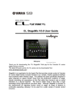
M7CL StageMix V3.0 User Guide Welcome: Thank you for downloading the “M7CL StageMix” iPad app for the Yamaha M7CL digital mixing consoles. This version of StageMix is for use with M7CL firmware V3.5 and higher. The latest firmware version for M7CL can be downloaded from www.yamahaproaudio.com StageMix is an application for the Apple iPad that provides remote control of Yamaha M7CL digital mixing console functions via a simple, intuitive graphical interface from anywhere within wireless range. The software has been specifically designed to allow engineers to adjust monitor mixes from the performers’ positions on stage, directly controlling mix parameters via the iPad rather than having to rely on verbal directions to a second engineer. The result is better mixes in less time; a huge advantage during high-pressure pre-show setup. Although StageMix is focused on the requirements for adjusting monitor mixes on stage, its range of features is continually expanding, allowing it to be used for a wider variety of remote control functions. Yamaha Commercial Audio M7CL StageMix V3.0 User Guide CONTENTS Page 1.0 System Requirements 4 2.0 Wi-Fi Settings 4 3.0 Getting Started 3.1 M7CL Network Setup 3.2 iPad Wi-Fi Settings 3.3 StageMix Setup 3.3.1 OFFLINE DEMO Mode 3.3.2 Configure StageMix to Work with an M7CL Console 3.3.3 Select a Mixer and Begin Working 3.3.4 Edit Mixer Configurations 5 5 5 6 7 7 8 8 4.0 Mixer Window 4.1 Channel Bank Navigation 4.2 Channel Names and Colors 4.3 Faders 4.3.1 Long Faders 4.3.2 Navigation in Long Faders Mode 4.4 Channel ON 4.5 CUE 4.6 Master Bank 4.7 HA GAIN 4.7.1 Input Port 4.7.2 Phantom Power 4.7.3 Phase 4.8 SENDS ON FADERS 4.8.1 Mix Send Levels 4.8.2 Mix Sends ON 4.8.3 Stereo Mix Pan 4.9 DCA Faders 9 9 9 10 10 10 10 11 11 12 12 12 13 13 14 14 14 15 5.0 EQ & PAN 5.1 EQ 5.1.1 EQ Curve in Mixer Window 5.1.2 Selecting PEQ or GEQ 5.1.3 Accessing the EQ Editing Screens 5.2 PARAMETRIC EQ EDITING 5.2.1 HPF 5.2.2 EQ Bands 1 & 4 5.2.3 EQ ON 5.2.4 EQ RESET 5.2.5 EQ Type 5.3 GRAPHIC EQ EDITING 5.3.1 Navigation in the GEQ Overview Section 16 16 16 17 17 18 19 19 20 20 20 21 21 Page 2 Yamaha Commercial Audio 5.4 M7CL StageMix V3.0 User Guide 5.3.2 Rack Position 5.3.3 GEQ Type 5.3.4 Editing GEQ Bands 5.3.5 Navigation in the GEQ Editing Section 5.3.6 GEQ ON 5.3.7 GEQ FLAT 5.3.8 Copy/Paste PAN TO STEREO BUSSES 5.4.1 Balance 21 22 22 22 22 22 22 23 23 6.0 UTILITY 6.1 Mute Group Masters 6.2 Tap Tempo 6.2.1 Multi-Select 24 24 25 25 7.0 SCENE MEMORY 7.1 Current Scene 7.2 Decrement / Increment Scene 7.3 Scene List 7.4 Scene Range 7.5 Selected Scene 7.6 Store Scene 7.7 Undo Store 7.8 Recall Scene 7.9 Undo Recall 26 26 27 27 27 28 28 28 28 29 8.0 SETUP 8.1 Fader Delay 8.2 Input Meter Point 8.3 Output Meter Point 8.4 Filled EQ Graph 8.5 Enable Inc/Dec Scene Recall 8.6 Show Send Levels in Meter Bridge 8.7 Set EQ band to 0dB with Double-Tap 8.8 Set DCA to 0dB with Double-Tap 8.9 Channel Select – StageMix Follows Console 8.10 Channel Select – Console Follows StageMix 30 30 30 30 31 31 31 31 31 31 31 9.0 Troubleshooting 9.1 No Wi-Fi Available 9.2 Connection Error 9.3 Connection Lost 9.4 Graphic EQ Doesn’t Affect the Sound 9.5 Problems Moving Multiple Faders 9.6 StageMix Facebook Page 32 32 32 33 33 33 34 Page 3 Yamaha Commercial Audio M7CL StageMix V3.0 User Guide 1.0 System Requirements Apple iPad (1st generation iPad, iPad 2, or 3rd generation iPad) Yamaha M7CL digital mixing console with V3.5 firmware or higher (any model, including M7CL-48, M7CL-32, M7CL-48ES). Wi-Fi access point (preferably with 802.11n, 5GHz capability, though 2.4GHz and 802.11g will also work) CAT5 cable (to connect the console to a Wi-Fi access point) 2.0 Wi-Fi Settings Configure the Wi-Fi access point, following the manufacturer’s instructions. No special settings are needed, but using security such as WPA is highly recommended, to prevent unwanted devices from joining the network. Here are some suggested settings to assist less experienced Wi-Fi users: 1. 2. 3. 4. 5. Give the wireless network a name (this is the “SSID”). Choose a security mode (such as WPA) and password. Select the wireless mode (802.11g or n). In the case of “n”, select the wireless band (2.4 or 5GHz). If available, enable “Auto Channel Selection” so the wireless channel with the least interference will be selected. 802.11n networks at 5GHz are preferred because they allow faster communication between the iPad and the Wi-Fi access point. Practically, this could result in more accurate level metering with the StageMix app. Also, with 802.11n being a newer standard, it is less prone to interference from other wireless networks. Using a Wi-Fi access point with 2 or more external aerials is recommended to increase potential signal range. Booster aerials could be connected for a further increase in performance. Page 4 Yamaha Commercial Audio M7CL StageMix V3.0 User Guide 3.0 Getting Started 3.1 M7CL Network Setup I. Connect the Wi-Fi access point to the M7CL console’s network port via a CAT5 cable. Note that a cross-over cable will be needed with older access points that don’t have the “auto MDIX” function. Most recent devices will support “auto MDIX”, in which case a straight CAT5 cable can be used. II. Note the IP address and MAC address of the M7CL console - they will need to be entered into the iPad later. They can be found in the console as follows: a. Press the [SETUP] button on the M7CL touchscreen b. Press [NETWORK] on the M7CL touchscreen 3.2 iPad Wi-Fi Settings The iPad needs to be given a static IP address in the same range as the M7CL’s IP Address. a. Open the iPad “Settings” menu b. Select “Wi-Fi”, and choose the correct network c. Press the blue circle with the white arrow to the right of the selected network to edit the IP address. d. Select [Static]. Page 5 Yamaha Commercial Audio M7CL StageMix V3.0 User Guide e. IP Address: enter an IP Address similar to the one for the M7CL console, but with just the last number different. (For example, if the M7CL is 192.168.0.128, give an address to the iPad such as 192.168.0.127). f. Subnet Mask: enter “255.255.255.0” g. Router: enter the IP Address of your Wi-Fi Access Point (usually printed on the bottom of the device) h. Press the iPad’s Home button to exit the Settings menu. 3.3 StageMix Setup Launch the “M7CL StageMix” App The “Select Mixer” screen will appear. From this screen, you can do any of the following things: Access the OFFLINE DEMO mode to explore the features and user interface of M7CL StageMix. Page 6 Yamaha Commercial Audio M7CL StageMix V3.0 User Guide Configure StageMix to work with an M7CL console. Select an M7CL console that has already been configured to work with your iPad and begin using StageMix. 3.3.1 OFFLINE DEMO If [OFFLINE DEMO] is pressed in the “Select Mixer” screen, the functions of StageMix will operate independently of any mixing console. It is a useful way to demonstrate and learn how to use the app without the need for a mixer. Level meters and most Scene Memory functions do not work in this mode. 3.3.2 Configure StageMix to Work with an M7CL Console i. Press [ADD MIXER] to open the following screen: ii. Tap on the blank Name field and enter a name for your M7CL console using the iPad’s onscreen keyboard. iii. Enter the M7CL console’s IP address noted in 3.1. The default IP Address may not need to be changed but confirm this in the Network Setup screen of the M7CL console (refer to 3.1). If you need to modify the IP Address in StageMix, make sure you include the dots between the sets of numbers (as shown above). iv. Enter the M7CL console’s MAC address noted in 3.1. When entering the MAC Address, the colons between sets of characters will be automatically added by StageMix. v. Select the Model of M7CL console. vi. Press the [ADD MIXER] button at the bottom of the screen. Page 7 Yamaha Commercial Audio M7CL StageMix V3.0 User Guide 3.3.3 Select a Mixer and Begin Working If your iPad has been configured to work with an M7CL console, select the mixer from the list and press [CONNECT]. (The model of mixer (M7CL-48 or M7CL-32) will appear in smaller text below the mixer’s name.) The message “Syncing With M7CL…” will appear while StageMix is obtaining parameters from the console. After this process is complete, the Mixer window will appear and StageMix is ready to be used. If StageMix cannot connect with your M7CL console, refer to the Troubleshooting section (9.0) at the end of this document for possible solutions. 3.3.4 Edit Mixer Configurations The parameters of a saved Mixer Configuration can be viewed and edited by tapping the right arrow button next to a mixer’s name. This will open the Edit Mixer screen which allows the Name, IP Address and MAC Address to be verified and edited using the procedures described in section 3.3.2. After editing, press [SAVE MIXER] to save any changes. Page 8 Yamaha Commercial Audio M7CL StageMix V3.0 User Guide 4.0 Mixer Window The main page of the StageMix is called the “Mixer” window. It shows the EQ curves, Pan positions, CUE and ON buttons, faders and level meters, and channel names and colors for eight adjacent channels. Across the top of the screen, level meters and faders are displayed in blocks of channels for mono Input Channels 1-48, Stereo Input Channels 1-4, Mix and Matrix busses, and the Master Stereo and Mono busses. This is the “Navigation/Meter Bridge”. 4.1 Channel Bank Navigation Press any of the “Navigation/Meter Bridge” blocks to select the bank of channels to be viewed and controlled in the channel strips below. 4.2 Channel Names and Colors The name of each channel appears in StageMix as it does in the M7CL console. The names are dimmed if the channel is switched off. A bar above each channel name displays the color based on the channel type. Double-tap on the channel name in the Mixer window to edit the name (colors cannot be edited). Type in a name and press [return]. Alternatively, navigate to another channel using the left/right cursor buttons above the keyboard. This allows multiple channels to be named before closing the keyboard. Page 9 Yamaha Commercial Audio 4.3 M7CL StageMix V3.0 User Guide Faders Each fader has its channel number displayed on its cap. The fader cap must be touched to allow the level to be adjusted. When a fader cap is touched, its background will lighten and its current dB value will be displayed. Using the iPad’s multi-touch facility, up to eight faders can be moved simultaneously. Note: “Multitasking Gestures” must be turned Off in the iPad in order to allow four or more faders to be adjusted simultaneously (refer to 9.5 for details). 4.3.1 Long Faders Press the [LONG FADERS] button at the bottom-left corner of the Mixer window to allow more accurate adjustment of fader levels. In this view, EQ, Pan and the “Navigation/Meter Bridge” are not visible. 4.3.2 Navigation in Long Faders Mode Although the “Navigation/Meter Bridge” is not visible in Long Faders mode, it is possible to navigate up or down in banks of 8 channels using the left/right arrow buttons in the upper left area of the Mixer window. Press the [LONG FADERS] button in the bottom-left corner again to return to the Mixer Overview. 4.4 Channel ON Press [ON] to change the on/off status of the channel. The button is green when the channel is on. When a channel is off, its name and level meter will dim and its fader position shown in the “Navigation/Meter Bridge” will also dim. If a channel is muted as part of a Mute Group, the ON button will blink. Page 10 Yamaha Commercial Audio 4.5 M7CL StageMix V3.0 User Guide CUE The [CUE] buttons for each channel control the mixer’s Cue functions. Their operation mode corresponds to the status of the [LAST CUE] button on the left side of the Mixer Overview. When the [LAST CUE] button is highlighted yellow, only one channel can be cued at a time. When this button is grey, multiple channels can be cued simultaneously. This is equivalent to Mix Cue mode in the M7CL console. The [CUE CLEAR] button will cancel any cues that have been activated. This is useful when there are multiple cues to cancel, and when some are hidden in other layers. 4.6 Master Bank Pressing the [Master] block in the “Navigation/Meter Bridge” will cause channels from the master section to appear in the fader strips. Included in this block are the Stereo Master channel, Mono Master channel and the Monitor Level and On control. Note: there are two EQ thumbnails above the Stereo Master channel. Parametric EQ is always linked for the left and right sides of the Stereo Master channel. However it is possible to have independent GEQs assigned to the left and right side of the Stereo Master. Page 11 Yamaha Commercial Audio 4.7 M7CL StageMix V3.0 User Guide HA GAIN The gain for each input channel can be controlled using the faders in StageMix. Press the [HA GAIN] button in the lower left area of the Mixer window to enter HA GAIN mode. This button will turn red and the background behind the channel faders will become red to indicate that StageMix is in HA Gain control mode. Note: the [HA GAIN] button will only appear when a bank of Input Channels are selected since there are no Gain parameters for Output Channels. Faders can be moved to change the HA Gain for each channel. The gain value of each head amp will be displayed above the fader while any fader cap is being touched. Up to 8 faders can be adjusted simultaneously. Faders will only appear for channels that have a head amp available. 4.7.1 Input Port When HA GAIN mode is active, the input port assigned to each channel will be displayed at the top of each channel strip (EQ and Pan are not displayed when HA GAIN mode is active). Input Port is a display-only parameter and cannot be edited from StageMix. 4.7.2 Phantom Power The 48V phantom power status for each input channel is also displayed at the top of each channel strip when HA GAIN mode is active. The 48V indicator will appear in red when phantom power is active. Phantom Power status is display-only and cannot be edited from StageMix. 4.7.3 Phase Page 12 Yamaha Commercial Audio M7CL StageMix V3.0 User Guide The Phase setting for each input channel appears near the top of the channel strips when HA GAIN mode is active. The Phase setting can be edited from StageMix by pressing this button. The button will have a grey background when the Phase setting is normal and will change to an orange background when Phase is reversed. 4.8 SENDS ON FADERS Press the [SENDS ON FADERS] button in the left column of the Mixer screen to access sends to Mix Busses. In “SENDS ON FADERS” mode, each fader controls the send level from its channel to the currently selected Mix. The fader level indicators in the “Navigation/Meter Bridge” will show the positions of all the Mix Send Levels if the appropriate Preference is On in the Setup screen (refer to 8.6). The large [MIX ON FADERS] button displays the currently selected Mix Bus number and its name. The color of this button matches those used in the M7CL console. [CUE] and [ON] buttons appear below the [SENDS ON FADERS] button, allowing the currently active Mix Bus to be Cued and turned On/Off. There are two ways to select a target Mix Bus: a) Use a swipe gesture on the [MIX ON FADERS] button to increment/decrement through the Mix and Matrix Busses. Page 13 Yamaha Commercial Audio b) M7CL StageMix V3.0 User Guide Press the [MIX ON FADERS] button to access a popup screen which allows direct selection of any Mix or Matrix Bus. Choose the “Target Mix Bus” from Mix 1-16 and Matrix 1-8. The currently selected Mix will appear as a white button with a check mark. Stereo pairs appear as single large buttons. When a Mix, Matrix or Master block is selected in the “Navigation/Meter Bridge”, the [SENDS ON FADERS] button is not available. 4.8.1 Mix Send Levels When in “SENDS ON FADERS” mode, the fader in each channel strip controls the level being sent from that channel to the currently selected Mix Bus. Note: if a Mix Bus is set to “Fixed” mode, send levels to that Mix Bus are fixed at 0dB and cannot be adjusted. Mix Send faders will not appear when a Mix Bus set to “Fixed” mode is selected. 4.8.2 Mix Sends ON In “SENDS ON FADERS” mode, the [ON] button in each channel strip is used to turn On/Off the Mix Send from each channel to the currently selected target Mix bus. 4.8.3 Stereo Mix Pan When a Stereo Mix Bus is active as the “Target Mix Bus”, a Pan slider will be available at the top of each channel strip in “SENDS ON FADERS” mode. Adjusting this slider will change the Pan position for that channel’s send to the currently active Stereo Mix Bus. The Pan position’s numerical value appears above the slider. If the Pan Link function is active for the currently active Stereo Mix Bus, a link icon will appear below the Pan slider. When Pan Link is active, adjusting a channel’s Pan slider will affect the Pan parameter for that channel to the Master Stereo Bus and all other linked Stereo Mix Busses. Page 14 Yamaha Commercial Audio M7CL StageMix V3.0 User Guide Note: Pan Link mode for each Stereo Mix Bus can only be activated in the console, not from StageMix. To exit “SENDS ON FADERS” mode, press the [SENDS ON FADERS] button in the left column. 4.9 DCA FADERS Press the [DCA] button to access the console’s 8 DCAs. A green LED will appear next to each DCA fader when it is set to exactly 0dB. DCA faders can be quickly set to exactly 0dB by double-tapping on the fader if the relevant Preference is On in the Setup screen (refer to 8.8). Press the [DCA] button again to exit the DCA fader bank and return to the previously selected bank. Alternatively, press any bank in the “Navigation/Meter Bridge” to directly access that fader bank. Page 15 Yamaha Commercial Audio M7CL StageMix V3.0 User Guide 5.0 EQ & PAN The thumbnail area at the top of each channel strip displays an EQ curve or the Pan position for that channel. The buttons to the left of the thumbnails are used to select between EQ and PAN mode by tapping on the left or right cursor button. 5.1 EQ Every channel in the M7CL console has a dedicated Parametric EQ (PEQ). M7CL consoles also have Graphic EQs (GEQs) that can be assigned (inserted) on input or output channels. Note: assignment of GEQs to channels must be done on the console and cannot be done in StageMix. 5.1.1 EQ Curve in Mixer Window The EQ curve section on the Mixer Window will show the user whether a GEQ is available on any channel. If a GEQ is available on a channel in addition to PEQ, the user will be able to view the curve for either of these EQs and access the editing screen for either type of EQ. Green and blue dots below each EQ curve indicate the types of EQ available on that channel, and the type of EQ (PEQ or GEQ) that is currently displayed for that channel. A green dot indicates PEQ and a blue dot indicates GEQ. When only PEQ is currently available on a channel, no dots will appear below the curve. (In Demo mode, GEQs appear on Mix busses1, 7, 8 and Mono). In the example above: Mix Bus 1 has both PEQ and GEQ available, and GEQ is currently being displayed (the blue dot is solid and the curve is blue). Mix Bus 2 has both PEQ and GEQ available, and PEQ is currently being displayed (the green dot is solid and the curve is green). Page 16 Yamaha Commercial Audio M7CL StageMix V3.0 User Guide Mix Busses 3-8 have only PEQ available so no dots are displayed below their EQ curves. 5.1.2 Selecting PEQ or GEQ On any channel displaying both a green and a blue dot below the EQ curve, the user can select either of those EQ types to be displayed by using a swipe gesture in the EQ curve area. If a PEQ curve is currently displayed, swiping from right to left will cause the GEQ curve to be displayed. If a GEQ curve is currently displayed, swiping from left to right will cause the PEQ curve to be displayed. 5.1.3 Accessing the EQ Editing Screens To access PEQ or GEQ editing, tap on the EQ curve to open the appropriate EQ Editing Screen. If a PEQ curve is displayed, the PEQ editing screen will be accessed. If a GEQ curve is displayed, the GEQ editing screen will be accessed. Note: the EQ editing screen will be accessed when the finger is removed from the curve. Swipe gestures will not cause the Editing screen to be accessed. Page 17 Yamaha Commercial Audio 5.2 M7CL StageMix V3.0 User Guide PARAMETRIC EQ EDITING The current channel’s Name, Color, Fader, Level Meters, [ON] and [CUE] buttons are shown in the left column. At the bottom-left, there are “previous” and “next” arrow buttons for navigating to different channels. Note: the In/Out meters display the levels going In and Out of the EQ section. One band of Parametric EQ can be adjusted at a time. Press one of the green circles to select the band, and it will be highlighted yellow. EQ bands in StageMix are labelled as follows: HP = HPF (input channels only) 1 = Low Band 2 = Low-Mid Band 3 = High-Mid Band 4 = High Band The current values for Freq, Gain and Q will be displayed for the currently selected EQ band. Gain and Frequency can be adjusted by dragging the circle around the graph. Q is adjusted by using the iPad’s “pinch” gesture: hold one finger (or thumb) on the screen while moving another finger closer to or further away from the first. Page 18 Yamaha Commercial Audio M7CL StageMix V3.0 User Guide TIP___________________________________________________________ The most comfortable and accurate way of adjusting Q is to use a vertical pinch movement with the thumb and forefinger. ______________________________________________________________ While an EQ band is being moved, the parameter value will turn yellow to indicate that it has changed. The little arrows show which direction the band should be moved to return to its previous position. In some cases, it may be necessary to adjust the gain without altering the frequency. Or to adjust the frequency without changing the gain. In this case, the “Gain Lock” or “Frequency Lock” functions can be used. These buttons are located at the top of the EQ graph. The “Lock” buttons affect all 4 bands (but not the HPF). When a band is adjusted, the locked parameter value becomes red. The lock function is automatically turned off when you navigate to a different channel or select a different EQ band. 5.2.1 HPF When any input channel is selected in the EQ Editing Screen, an [HPF] button appears at the top of the EQ graph. Press this button to switch the HPF on/off. When the button is green, the HPF is On. HPF has no Gain or Q parameter: only frequency. When an output channel is selected in the EQ Editing Screen, the [HPF] button will only appear if band 1 is assigned to the HPF function. 5.2.2 EQ Bands 1 & 4 EQ bands 1 & 4 have additional choices of band-type. Both these bands can be assigned to function as a shelf or a bell, and band 4 can also function as a Low Pass Filter. Band 1 can also be a HPF for Mix, Matrix and Stereo/Mono Master channels. When one of these bands is selected, the relevant additional buttons are shown above the EQ graph. Page 19 Yamaha Commercial Audio M7CL StageMix V3.0 User Guide 5.2.3 EQ ON The channel EQ can be switched on/off with the [EQ ON] button towards the top-right of the EQ screen. It is green when the EQ is on. When the EQ is switched off, the EQ curve will be grey. 5.2.4 EQ RESET The [RESET] button above the EQ curve allows the EQ to be reset to either its Default values or to Flat. After pressing [RESET], an “Are You Sure?” popup will be displayed before the action is executed. Selecting “Default EQ” will reset all EQ parameters for the selected channel back to their default values, including HPF. Selecting “Flatten EQ” will set the Gain of bands 1-4 to 0dB, but will not change the Q and Frequency values. Select “No” to cancel and exit this function. 5.2.5 EQ TYPE The default EQ Type for every PEQ is Type I. This can be changed to Type II by pressing the [II] button at the top of the EQ editing screen. To exit from the EQ window and return to the Mixer window, press the [MIXER] button at the top-right of the display. Page 20 Yamaha Commercial Audio 5.3 M7CL StageMix V3.0 User Guide GRAPHIC EQ EDITING GEQ Overview In the upper portion of the GEQ Editing Screen, the complete GEQ curve is displayed along with the gain positions for all 31 bands. White dots represent the position for each of the 31 bands. (These dots change to yellow and become larger when they are being touched in the Editing section below.) The current channel’s Name, Color, Fader, Level Meters, [ON] and [CUE] buttons are shown in the left column. At the bottom-left, there are “previous” and “next” arrow buttons for navigating to different channels. Pressing these buttons will only access other channels that have GEQs assigned to them. Note: the In/Out meters display the levels going In and Out of the EQ section. 5.3.1 Navigation in the GEQ Overview Section Tapping anywhere in the GEQ Overview will cause the GEQ sliders in the Editing section to jump to that range of the GEQ (represented by a light grey area in the overview). Touching the selected range in the Overview and dragging it left / right will scroll the range of GEQ sliders. 5.3.2 Rack Position In the upper-left area of the GEQ screen, the Rack position of the channel’s GEQ will be displayed. In the screenshot above, this GEQ is located in rack position 1B. Page 21 Yamaha Commercial Audio M7CL StageMix V3.0 User Guide 5.3.3 GEQ Type Next to the Rack position, the type of GEQ is identified as either “31 Band” or “Flex 15”. In the case of a Flex 15 GEQ, a larger-sized number indicates the remaining number of available bands for that GEQ. As each band is adjusted away from 0dB, the number of available bands will decrease. This number will turn red when no further bands are available to be edited. 5.3.4 Editing GEQ Bands Sliders in the lower portion of the GEQ screen allow each band of EQ to be edited. Multiple bands can be edited simultaneously with up to 10 bands appearing at any one time. Touch the silver sliders for one or more bands and move them vertically to adjust the gain for each band. The gain parameter value will appear in a floating display above any GEQ slider while it is being touched. Note: sliders will become transparent and cannot be operated when there are no remaining bands available for a Flex 15 GEQ. 5.3.5 Navigation in the GEQ Editing Section In addition to navigation in the upper GEQ Overview section, swipe gestures can be used to navigate through the GEQ bands in the lower editing section. 5.3.6 GEQ ON The [GEQ ON] button in the upper-right part of this screen turns the GEQ On or Off. The button appears blue when GEQ is On and turns grey when GEQ is Off. When Off, the GEQ display curve will also turn light grey. 5.3.7 GEQ FLAT The [FLAT] button will reset all GEQ bands to 0dB. A confirmation dialog will appear before this function is executed. 5.3.8 Copy/Paste GEQ parameter settings can be copied and pasted from one GEQ to another. Press the [COPY] button to capture the parameter settings of the current GEQ. Navigate to another channel that has a GEQ assigned and press [PASTE]. Note: the [PASTE] button will only be available when a suitable GEQ has been selected. Only 31 Band GEQs that use up to 15 bands can be copied to a Flex 15 GEQ. Settings copied in the M7CL console cannot be pasted in StageMix. To exit from the GEQ window and return to the Mixer window, press the [MIXER] button at the top-right of the display. Page 22 Yamaha Commercial Audio 5.4 M7CL StageMix V3.0 User Guide PAN TO STEREO BUSSES When PAN mode is selected using the buttons described in section 5.0, all 8 thumbnail images will display a slider showing the position of the Pan to the Stereo Busses for each channel. A numeric Pan position value appears above each slider. Double-tap on the slider to set the Pan position to Center. Text shows whether each channel is assigned to the ST, Mono or the LCR busses. ST is displayed in red if the channel is assigned to the Stereo bus. M is displayed in yellow if the channel is assigned to the Mono bus. LCR is displayed in white if the channel is assigned to LCR. These text indicators are display-only and these assignments cannot be edited from StageMix. 5.4.1 Balance “BAL” will be displayed below the pan slider for Stereo Input channels. The pan slider is used to adjust the Balance. Mix and Matrix Busses provide a Balance control when they are configured as stereo pairs. “BAL” will be displayed below the pan slider when a Mix or Matrix Bus is configured as a stereo pair. Page 23 Yamaha Commercial Audio M7CL StageMix V3.0 User Guide 6.0 UTILITY The UTILITY button provides access to the following functions: Mute Group Masters Tap Tempo Press the [UTILITY] button on the left side of the Mixer window to enter this mode. To exit from the UTILITY mode, press the [UTILITY] button, another mode button, or any bank in the “Navigation/Meter Bridge”. 6.1 MUTE GROUP MASTERS 8 buttons are provided to function as Master switches for the console’s Mute Groups. Press [MUTE GROUP X] to mute channels assigned to that Mute Group. The button will appear red when a group is muted. The channel [ON] buttons in the Mixer Window will blink to indicate that a channel has been muted as part of a Mute Group. Note: assignment of channels to Mute Groups must be done in the console. Page 24 Yamaha Commercial Audio 6.2 M7CL StageMix V3.0 User Guide TAP TEMPO The Tap Tempo section in the UTILITY mode allows you to tap BPM values into effects in the console that include BPM parameters. Select the relevant effect from the list of 4 effects in the left side of this section. Effects which do not have a BPM parameter will be greyed out and cannot be selected. Tap on the large button on the right side of the Tap Tempo section. The BPM value will be calculated by StageMix and transmitted to the selected effects in the console. 6.2.1 Multi-Select Multiple effects can be selected allowing the BPM parameters to be set for all selected effects simultaneously. Set the MULTI-SELECT function to ON to enable selection of more than one effect simultaneously. The currently selected effects will be highlighted with white text on a blue background. Tap a highlighted effect to de-select it. Note: the Multi-Select function is only available when using iOS 5 or higher. Page 25 Yamaha Commercial Audio M7CL StageMix V3.0 User Guide 7.0 SCENE MEMORY The Current Scene Memory number and title (name) are displayed in the upper-left corner of the StageMix Mixer window. An “E” indicator will be displayed if the Scene has been edited since it was last stored or recalled. The Scene Memory area in the Mixer window also functions as a button which can be pressed to access the Scene Memory window. 7.1 CURRENT SCENE The Current Scene Memory number and title also appear in the upper part of the Scene Memory window. The Scene Comment also appears in this area. Page 26 Yamaha Commercial Audio M7CL StageMix V3.0 User Guide 7.2 DECREMENT / INCREMENT SCENE Buttons in the upper right part of the Scene window allow instant recall of the Previous and Next Scene relative to the current Scene. For example, if the Current Scene is 005, pressing the [INC SCENE] button will recall Scene 006 in the console. However, if Scene 006 is empty, the next highest Scene containing data will be recalled. Note: the [DEC SCENE] and [INC SCENE] buttons will only appear in the Scene window if the related preference has been enabled in the Setup window (refer to 8.7). 7.3 SCENE LIST When the Scene Memory window is accessed for the first time after launching StageMix, the Scene List will be sent from the console to StageMix. Note: if StageMix loses its Wi-Fi connection to the console, the Scene List will need to be sent from the console again after the connection is re-established. 12 Scenes can be viewed simultaneously in the Scene List. Drag up and down in the list to access other Scenes. The Current Scene will be indicated by a check mark to the right of the Scene Title (the current scene is also displayed in the upper left portion of the Scene screen). Empty Scene Memories locations will be displayed with a grey background. Scene titles that have not been sent from the console to StageMix will be indicated by a question mark. 7.4 SCENE RANGE If the console contains a large number of Scenes, it may take some time for the complete Scene List to be transmitted to StageMix. To minimize the time required to update the Scene List in StageMix, a Scene Range can be set so that only necessary Scenes are sent from the console to StageMix. By default, the Scene Range is set to the full range from Scene 0 to 300. By pressing the [SCENE RANGE] button, the user can define the range of Scenes that will be updated in the Scene List. This range will be remembered by StageMix and will continue to be used until it is changed. To update the Scene Range, tap the [SCENE RANGE] button on the right side of the Scene Memory window. A small popup will appear. Tap the [FIRST] or [LAST] button to access the iPad’s onscreen keyboard. Enter a number for the First and/or Last Scenes in the Range and press Return. Then press the [UPDATE RANGE] button in this popup to update the Scene List based on the currently active range. Page 27 Yamaha Commercial Audio M7CL StageMix V3.0 User Guide 7.5 SELECTED SCENE Selecting a Scene in the Scene List will cause it to be displayed in white text with a blue background. Further details about this selected Scene will be displayed to the right of the Scene List. These details include the following: SCENE TITLE The scene title can be edited by tapping on the title. The iPad’s keyboard will appear. Tap the X button next to the title to clear the current title before typing in a new title. Then press Return. SCENE COMMENT The Scene Comment is displayed and can be edited using the same procedure described for the Scene Title. TIME STAMP This shows the time and date that the Scene was last stored. The Time Stamp is display-only. SCENE STATUS (FOCUS and FADING) This section displays the status of Focus and Fade Time functions for the selected Scene Memory. 7.6 STORE SCENE Pressing the [STORE] button will cause the current console parameter settings to be stored to the currently selected Scene Memory (highlighted in the Scene List). a) b) c) d) Press [STORE] and the iPad’s onscreen keyboard will appear. To enter a new title for this Scene, tap the X button next to the Scene Title to clear the current title. Type in a new title and press the [STORE] button or Return on the keyboard. A confirmation popup will appear if the STORE CONFIRMATION preference is ON in the console. 7.7 UNDO STORE Pressing the [UNDO STORE] button will cancel the most recent Scene Store operation. 7.8 RECALL SCENE Pressing the [RECALL] button will cause the currently selected Scene Memory (highlighted in the Scene List) to be recalled by the console. A confirmation popup will appear if the RECALL CONFIRMATION preference is ON in the console. When a Scene Memory is recalled by the console, StageMix must synchronize itself with the current console parameter data. The status of this synchronization will be indicated by a progress bar which appears below the Current Scene number in the upper left section of the Scene Memory screen. You can exit the Scene Memory screen while synchronization is occurring but Page 28 Yamaha Commercial Audio M7CL StageMix V3.0 User Guide you will not be able to edit any parameters in StageMix until synchronization has been completed. 7.9 UNDO RECALL Pressing the [UNDO RECALL] button will cause the most recent Scene Recall to be cancelled. StageMix will need to synchronize with the console after executing a Scene Recall UNDO. Press the [MIXER] button in the top-right corner of the Scene Memory window to return to the Mixer window. Page 29 Yamaha Commercial Audio M7CL StageMix V3.0 User Guide 8.0 SETUP Press the [SETUP] button in the upper left area of the Mixer window to open a new window which allows user preferences to be selected. iPad Status Bar The iPad’s Status Bar is visible in this screen, allowing the Wi-Fi signal strength and the battery charge status to be viewed. Press [Done] in the top-right corner to return to the Mixer window. 8.1 Fader Delay This is a safety function to avoid accidental fader movements. The value set here is the time needed to wait between touching a fader and being able to move it. 8.2 Input Meter Point Metering for Input Channels in StageMix can be taken from one of three points in the signal path: 8.3 Pre HPF Pre Fader Post On Output Meter Point Metering for Output Channels in StageMix can be taken from one of three points in the signal path: Pre EQ Pre Fader Post On Page 30 Yamaha Commercial Audio M7CL StageMix V3.0 User Guide 8.4 Filled EQ Graph When this preference is ON, the EQ graph will be filled in, as it is on the M7CL screen. When it is off, only the outline of the graph will be shown. 8.5 Enable Inc/Dec Scene Recall When this preference is ON, buttons will appear in the Scene Memory screen that allow instant recall of the Next or Previous Scene Memory. Refer to section 7.2 for more details. 8.6 Show Send Levels in Meter Bridge When this preference is ON, the send levels for the currently selected “MIX ON FADERS” will appear in the “Navigation/Meter Bridge” in “SENDS ON FADERS” mode. If this preference is OFF, the input levels will be displayed. 8.7 Set EQ band to 0dB with Double-Tap When this preference is ON, Parametric and Graphic EQ Gains can be set to 0dB by double-tapping on the EQ band. 8.8 Set DCA to 0dB with Double-Tap When this preference is ON, a DCA fader can be set to exactly 0dB by double-tapping on the fader cap. 8.9 Channel Select – StageMix Follows Console When this preference is ON, the currently selected channel in the StageMix Parametric and Graphic EQ screens will follow the Selected Channel in the M7CL console. 8.10 Channel Select – Console Follows StageMix When this preference is ON, the Selected Channel in the M7CL console will follow the currently selected channel in the EQ screens of StageMix. Page 31 Yamaha Commercial Audio M7CL StageMix V3.0 User Guide 9.0 Troubleshooting 9.1 No Wi-Fi Available If this message appears after launching StageMix, this indicates that the iPad is not connected to a Wi-Fi access point or that Wi-Fi may be switched off in the iPad. Refer to sections 2.0 and 3.2 for details about Wi-Fi hardware configuration and iPad Wi-Fi settings. 9.2 Connection Error If this message appears after selecting a mixer and pressing [CONNECT], this indicates that StageMix cannot connect to the console. This may be due to incorrect IP Address or MAC Address settings in either the console or StageMix. Verify that the settings in the console match the settings in StageMix. Refer to 3.1 and 3.3.2 for details about these settings. This problem will also occur if the console is not turned On. Page 32 Yamaha Commercial Audio M7CL StageMix V3.0 User Guide 9.3 Connection Lost If StageMix loses its connection to the console, the following message will appear. Operation of StageMix is not possible while this message box is onscreen. StageMix will automatically attempt to reconnect to the console. If this is successful, StageMix will re-synchronize with the console data and operation will become available again. 9.4 Graphic EQ Doesn’t Affect the Sound If a Graphic EQ is assigned to an input channel or Mix/Matrix bus but it doesn’t seem to be affecting the sound on that channel, it could be that the Insert for that channel has been switched Off. Check the state of the Insert ON switch in the console. 9.5 Problems Moving Multiple Faders ・If Multitasking Gestures (in iOS 4.3 or higher) is ON, it may not be possible to move more than three faders simultaneously in StageMix. When using StageMix, it is recommended that Multitasking Gestures be turned OFF. a. Open the iPad “General” menu. b. Set the button for “Multitasking Gestures” to OFF. ・If the "Zoom" function in the "Accessibility" menu is ON, it may not be possible to move more than two faders simultaneously in StageMix. When using StageMix, it is recommended that "Zoom" be turned OFF. Page 33 Yamaha Commercial Audio M7CL StageMix V3.0 User Guide a. Open the iPad "General" menu. b. Select "Accessibility,” and then set the button for “Zoom” to OFF. 9.6 StageMix Facebook Page To exchange information and tips with other StageMix users, please visit our Facebook page: http://www.facebook.com/StageMix Special Notices • The software and this User Guide are the exclusive copyrights of Yamaha Corporation. • Copying of the software or reproduction of this manual in whole or in part by any means is expressly forbidden without the written consent of the manufacturer. • Yamaha makes no representations or warranties with regard to the use of the software and documentation and cannot be held responsible for the results of the use of this manual and the software. • The screen displays as illustrated in this User Guide are for instructional purposes, and may appear somewhat different from the screens which appear on your computer. • Future upgrades of application and system software and any changes in specifications and functions will be announced separately. • Apple, the Apple logo, iPad, and iOS are trademarks of Apple Inc., registered in the U.S. and other countries. • The company names and product names in this User Guide are the trademarks or registered trademarks of their respective companies. Page 34