1
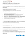
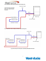
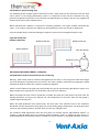
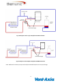
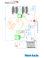
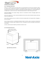
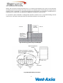
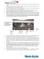
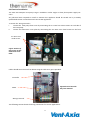
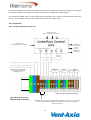
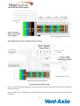
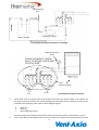
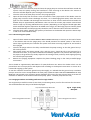
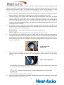
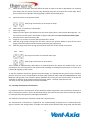
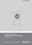
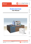
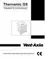
Thernamic GS
Single Compressor Compact Heat Pump
Installation & Commissioning
PLEASE RETAIN THESE INSTRUCTIONS WITH THE PRODUCT.
Contents Page
Section
Description
Page
4
1.......................
Notes sheet ..................................................................................
2.......................
Safety Information ........................................................................ 5
2.1...........................
Access ...................................................................................................................... 5
2.2...........................
Lighting .................................................................................................................... 5
2.3...........................
Tools and consumables ........................................................................................... 5
2.4...........................
Handling ................................................................................................................... 5
2.5...........................
Residual hazards ...................................................................................................... 5
2.6...........................
Freezing ................................................................................................................... 5
2.7...........................
Disposal/decommissioning ...................................................................................... 5
3.......................
General product information ........................................................ 6
3.1...........................
Equipment delivery and handling ............................................................................ 6
3.2...........................
Vent-Axia Compact technical data .......................................................................... 7
4.......................
Installation.................................................................................... 8
4.1...........................
The Golden Rules of installing a heat pump ............................................................ 8
4.2 ..........................
Underfloor heating schematics ............................................................................... 8
4.2.1........................
Underfloor with a single manifold. Space heating only ........................................... 9
4.2.2........................
Underfloor with multiple manifolds. Space heating only ........................................ 9
4.3...........................
Radiators. Space heating only ................................................................................. 10
4.4...........................
Domestic Hot Water - Schematic ............................................................................ 10
4.4.1........................
Type of DHW tank ................................................................................................... 11
4.4.2........................
DHW tank size ......................................................................................................... 11
4.4.3........................
Immersion heater .................................................................................................... 11
4.4.4........................
Three Port Diverting Valve ...................................................................................... 11
4.4.5........................
Tank Thermostat ...................................................................................................... 11
4.4.6........................
DHW Timeclock ....................................................................................................... 11
4.5...........................
Mechanical Installation ........................................................................................... 14
4.5.1........................
Locating the Heat Pump .......................................................................................... 14
4.5.2........................
Recommended Clearances ...................................................................................... 14
4.5.3........................
Installation of the heat pump .................................................................................. 15
4.6...........................
Electrical Installation ............................................................................................... 17
4.6.1........................
Single Phase ............................................................................................................. 18
4.6.1.1.....................
Single Underfloor Control Unit ................................................................................ 18
4.6.1.2 ....................
Multiple Underfloor Control Units .......................................................................... 19
4.6.1.3.....................
Radiator with Thermostat ....................................................................................... 19
4.6.2........................
Three Phase Power Supplies .................................................................................... 20
4.6.3........................
DHW time clock and 3 way diverting valve wiring .................................................. 20
4.6.4........................
Weather Compensation (Optional) ......................................................................... 21
2
Contents Page
Section
Description
Page
5....................... Commissioning ............................................................................. 22
5.1........................... Purging the slinkies of air ....................................................................................... 22
5.1.1........................ Purging procedure for multiple slinkies ................................................................. 22
5.1.2........................ Adding antifreeze for multiple slinkies ................................................................... 24
5.1.2.1..................... Pressurizing the system .......................................................................................... 25
5.1.3........................ Purging procedure and adding antifreeze for single slinkies .................................. 25
5.1.4........................ Testing of antifreeze concentration ....................................................................... 27
5.1.5........................ Heating distribution and load side purging ............................................................ 28
5.1.6........................ Reassembling the heat pump ................................................................................. 28
5.2........................... Heat pump operation ............................................................................................. 29
5.3........................... Turning the heat pump on for the first time .......................................................... 29
5.4........................... Altering the flow temperature from the heat pump .............................................. 30
5.4.1........................ To read flow temperatures and refrigerant pressures ........................................... 31
5.4.2........................ To change the heat pump return flow temperatures ............................................ 31
6....................... Fault finding ................................................................................. 33
7....................... RTB and extended warranty statement ........................................ 34
7.1........................... Extending the RTB warranty .................................................................................. 34
7.1.1........................ Parts only ............................................................................................................... 34
7.1.2........................ Labour and parts .................................................................................................... 34
8....................... Antifreeze COSHH sheet…………………………………………………………….. 35
Antifreeze Safety data sheet ……………………………………………………….. 36
9....................... Heat pump settings sheet ............................................................. 37
3
Notes:——————————————————————
——————————————————————
——————————————————————
——————————————————————
——————————————————————
——————————————————————
——————————————————————
——————————————————————
——————————————————————
——————————————————————
——————————————————————
——————————————————————
——————————————————————
——————————————————————
——————————————————————
——————————————————————
——————————————————————
——————————————————————
——————————————————————
——————————————————————
——————————————————————
——————————————————————
——————————————————————
——————————————————————
——————————————————————
——————————————————————
——————————————————————
——————————————————————
4
2. Safety information
Safe operation of this unit can only be guaranteed if it is properly installed and commissioned in
compliance with the manufacturer’s requirements. General installation and safety instructions for pipeline
and plant construction, as well as the proper use of tools and safety equipment must also be complied
with.
Manufacturer:Vent-Axia Limited
Fleming way
Crawley,
West Sussex,
RH10 9YX
Tel 01293 441523
www.vent-axia.com
The product is designed and constructed to withstand the forces encountered during normal use. Use of
the product for any other purpose, or failure to install the product in accordance with these Installation
and Commissioning Instructions, could damage the product, will invalidate the warranty, and may cause
injury or fatality to personnel.
2.1 Access
Ensure safe access before attempting to work on the product. Arrange suitable lifting gear if required.
2.2 Lighting
Ensure adequate lighting, particularly where detailed or intricate work is required.
2.3 Tools and consumables
Before starting work ensure that you have suitable tools and / or consumables available.
2.4 Handling
Manual handling of large and /or heavy products may present a risk of injury. Lifting, pushing, pulling,
carrying or supporting a load by bodily force can cause injury particularly to the back. You are advised to
assess the risks taking into account the task, the individual, the load and the working environment and use
the appropriate handling method depending on the circumstances of the work being done.
2.5 Residual hazards
Many products are not self-draining. Take due care when dismantling or removing the product from an
installation.
2.6 Freezing
Provision must be made to protect products which are not self-draining against frost damage in
environments where they may be exposed to temperatures below freezing point.
2.7 Disposal/Decommissioning
Vent-Axia offer a life time decommissioning service for this product. This is available on a return to base
basis (carriage at users’ cost).
Disposal of any antifreeze water mix should follow the disposal instructions as laid out on the COSHH
Safety Data Sheet on page 37.
5
3. General Product Information
This manual explains how to install and commission a Vent-Axia ground source heat pump.
The Vent-Axia Compact Single Compressor Heat Pump is designed to provide a low cost renewable heat
source for a buildings heating system. In addition, and if required, the Vent-Axia Compact can also provide
domestic hot water. Heat pumps can provide lower running costs and will generate significantly lower
carbon emissions compared with traditional fossil fuels.
The Vent-Axia Compact Single Compressor Heat Pump is designed for straightforward installation and requires no specialist training to install. However the installation must conform to all relevant construction
and
electrical codes and comply with the requirements of the Microgeneration Certification Scheme
(MCS) MIS3005 ’Requirements for Contractors undertaking the Supply, Design, Installation, Set to Work
Commissioning and Handover of Microgeneration Heat Pump Systems’
3.1 Equipment delivery and handling.
Factory shipment
Prior to shipment, the Vent-Axia Compact Single Compressor Heat Pump is tested, calibrated and inspected to ensure proper operation.
Receipt of shipment
Each pallet should be inspected at the time of delivery for possible external damage. Any visible damage
should be recorded immediately on the carrier’s copy of the delivery slip.
Each pallet should be unpacked carefully and its contents checked for damage.
If it is found that some items have been damaged or are missing, notify Vent-Axia immediately and provide
full details. In addition, damage must be reported to the carrier with a request for their on-site inspection
of the damaged item and its shipping pallet.
Storage
If a Vent-Axia Heat Pump is to be stored prior to installation, the environmental storage conditions should
be at a temperature between 0°C and 70°C (32°F and 158°F), and between 10% and 80% relative humidity
(non-condensing).
Evaporator
Heat Exchanger
Compressor
Condenser Heat
Exchanger
Controller
Ground Array Water
Pump
MCBs
Heating Distribution
Water Pump
Pressure
Gauges
Fig 1. The internals of a heat pump
6
7
16
12
12
9.4
8.0
7.2
5.7
30
26
22
18
15
Amps
Max
running
Current
7 (9)
6 (7)
5 (6)
4.5 (5)
3 (4)
17 (22)
13 (18)
13 (16)
10 (12)
7 (10)
Amps
Typical
running
current
51
41
36
30
23
40
30
30
30
25
Amps
Typical
starting
current
2.5
2.5
2.5
2.5
2.5
4.0
4.0
2.5
2.5
2.5
mm
kW
Power
input*
Kg
110
100
95
90
85
3.2 (4.5)
2.6 (3.7)
2.3 (3.2)
1.8 (2.4)
1.4 (2.0)
110
100
95
90
85
Three Phase— 400 Volts AC 50 Hz
3.4 (4.6)
2.7 (3.8)
2.4 (3.3)
1.9 (2.5)
1.5 (2.1)
Single
Single
Single
Single
Single
Single
Single
Single
Single
Single
Number
Nominal dry Compressors
weight
Single Phase—230 Volts AC 50 Hz
Power
supply
cable size
(min)
900x550x570
900x550x570
900x550x570
900x550x570
900x550x570
900x550x570
900x550x570
900x550x570
900x550x570
900x550x570
HxWxD
Dimensions
28
28
28
28
28
28
28
28
28
28
mm OD
2.4
2.0
1.6
1.2
0.8
2.4
2.0
1.6
1.2
0.8
m2
Connection size Recommended
minimum heat
transfer area in
DHW tank (not
supplied)
For clarification of starting currents and details on how these figures are calculated please contact Vent-Axia.
The figures above are based on a rating to BS EN14511, 0 deg C from the ground, 35 deg C flow to underfloor. The figures in parentheses are values obtained to BS
EN14511, 0 deg C from the ground, 50 deg C flow to radiators.
* This figure includes the power consumption of the inbuilt water pumps
16
10
32
12
16
32
10
8
25
8
16
25
6
6
16
4
16
Amps
kW
4
Power
supply
rating
Nominal
Thermal
Output
3.2 Vent-Axia Compact Technical Details—Single Compressor
4. Installation
Note: Before actioning any installation observe the 'Safety information' in Section 1.
It is essential that the following installation guidelines are followed carefully.
The installation must conform to all relevant construction and electrical codes and comply with the
requirements of the Microgeneration Certification Scheme (MCS) MIS3005 ’Requirements for Contractors
undertaking the Supply, Design, Installation, Set to Work Commissioning and Handover of Microgeneration
Heat Pump Systems’
Any electrical work required to install or maintain this appliance should be carried out by a suitably
qualified electrician in accordance with current IEE regulations.
Any plumbing work should be carried out to local water authority and WRC regulations.
4.1 The Golden Rules of Installing a Heat Pump
1.
2.
3.
4.
5.
6.
7.
8.
9.
A ‘D’ Type MCB should be used for the heat pumps power supply. If this is not available a ‘C’ Type
can be used on single phase units fitted with smart starts.
Connect the heat pump using only plastic pipe.
Use the Vent-Axia recommended purge pump for purging the ground arrays and heat pump.
On the underfloor heating manifold(s), remove the thermal mixing valve(s) if fitted.
On the underfloor heating manifold(s), don’t fit electric actuators to more than 75% of the zones.
Remove the chrome screws on the water pumps, and check that both pumps are running, and
moving water before turning on the compressor (25 MCB on the unit) (See section 5.3).
Do not install the heat pump adjacent to or beneath bedrooms or noise sensitive areas.
Read this manual fully before commencing installation.
Do not connect the heat pump to a thermal store without consulting Vent-Axia first.
4.2 Underfloor Heating Schematics
The following section includes typical schematics of how a heat pump can be connected. Only the load
side is shown i.e. the heating distribution system. It is important to note that the schematics are only
general arrangements and hence do not illustrate all required valves or fittings.
On the underfloor heating manifold(s) remove any thermal mixing valves, if fitted.
To avoid the heat pump from short cycling, it is important that the underfloor is capable of accepting the
minimum load from the heat pump.
The easiest way to do this is simply to have some zones left “open” – i.e. without electric actuators. These
zones will still require thermostats so can call for heat when required. In houses, the best zones to chose
are ensuite bathrooms, and hallways, neither of which are likely to be overheated.
To avoid short cycling of the heat pump the smallest actuator controlled zone (plus all the open zones on
that manifold) should be capable of absorbing the minimum thermal load of the heat pump. This
minimum load is approximately 25% for single compressor heat pumps.
If a fully controlled zone system is required, then a buffer vessel will be required (ideally a two connection
tank). This can result in a lower overall efficiency of the system (due to the higher temperatures, pump
electricity usage, etc) and hence Vent-Axia would always advise that the ‘open zone’ method of avoiding
short cycling is used.
8
4.2.1 Underfloor with a single manifold. Space heating only
Fig 2 Heat Pump with Underfloor and a Single Manifold
Schematic
Vent-Axia Supply
4.2.2 Underfloor with a multiple manifolds. Space heating only
Vent-Axia Supply
Fig 3 Heat Pump with Underfloor and Multiple Manifolds Schematic
9
4.3 Radiators. Space heating only
The following section includes typical schematics of how a heat pump can be connected. Only the load
side is shown i.e. the heating distribution system. It is important to note that the schematics are only
general arrangements and hence do not illustrate all required valves or fittings. They are only a guide and
should not be used as full installation plans.
When operated with radiators to avoid short circulating problems, one bypass radiator should be left
‘open’, i.e. any TRV is removed. This radiator can be positioned in areas such as halls or bathrooms.
Vent-Axia would always recommend fitting an expansion vessel on the heating distribution circuit.
Fig 4 Heat Pump with
Radiators Schematic
Radiator with TRV
Bypass Radiator
Radiator with TRV
Vent-Axia Supply
Expansion vessel
Return
Flow
Heat Pump
4.4 Domestic Hot Water (DHW) —Schematic
The DHW option needs to be specified at time of ordering.
Warning - when a heat pump is used for heating domestic hot water, it may not get the water hot enough
to kill the dangerous Legionella that can breed in hot water cylinders. Alternative arrangements should
therefore be made to ensure the cylinder is pasteurised regularly.
Under normal conditions the heat pump will provide heat for the space heating distribution system at its
design temperature (typically 35oC for underfloor and 45-50oC for radiators).
When the DHW time clock calls for production of DHW, the three-port valve diverts the flow from the
heating distribution circuit into the indirect coil. The temperature of the water from the heat pump is
raised to approximately 50oC.
When the DHW production time period ends, the three port valve switches back to the underfloor
distribution and the temperature drops back to its space heating design temperature. The heat pump then
reverts to space heating mode or switches off if no zones are calling for heat.
The maximum DHW temperature that the heat pump can achieve will be approximately 50-55oC. In
summer, it could be higher, due to the warmer ground conditions. If 65oC is required all year round, it is
recommended that an immersion heater is linked to a second channel on the DHW timeclock and this is
10
programmed to operate for a period immediately following the DHW production. This means that the
majority of the heating load for the DHW is produced at a lower cost using the heat pump, as opposed to
using only the direct immersion heater.
If 50oC water is acceptable, then it is recommended that the immersion heater is programmed to raise the
temperature to 65oC once a week.
4.4.1 Type of DHW Tank
The larger size the coil within the tank, the better the heat transfer area and hence the better the DHW
performance will be.(Refer to table 3.2)
4.4.2 DHW Tank Size
The tank will need to be carefully sized to meet the DHW demand, based on the number of occupants and
should have an acceptable recovery rate. Due to the lower DHW temperature achieved by the heat pump,
a tank 30% larger than normal is recommended. This is due to the higher demand on the tank, as less cold
water is used at the point of use to mix the lower temperature DHW to an acceptable temperature.
4.4.3 Immersion Heater
Although not required by Building Regulations, it is generally advised that to provide legionella protection
the tank is raised above 60oC at least once a week. To provide this we would recommend that a 3 kW
electric immersion heater is fitted to the bottom of the tank, with its own dedicated 7- day timeclock. If
DHW is required higher than 50oC then it is advisable that the immersion heater is programmed to
operate for a period following the heat pump operation period to raise the temperature. This avoids the
immersion heater taking all of the load.
4.4.4 Three Port Diverting Valve
If the DHW option is ordered, a 3 port diverting valve (‘W’ plan) is provided by Vent-Axia and is used to
divert the flow when the timeclock calls for DHW production from space heating to the DHW tank. The
valve’s electrical connections are connected to the heat pump’s internal wiring. Please note connection ‘A’
is DHW and ’B’ is space heating.
4.4.5 Tank Thermostat
A tank thermostat is not required but maybe fitted and used as a tank safety stat if wired in series with the
time clock. This should be set at not less than 65oC.
11
Vent-Axia Supply
Fig 5 Underfloor with a single manifold and DHW Schematic
Vent-Axia Supply
Fig 6 Underfloor with multiple manifolds and DHW Schematic
Note: Additional circulation pumps with multiple manifolds depends on the system design.
12
13
DHW Tank
Hot water out to faucets
Cold feed in
7 day time clock
dedicated
controlled by
Immersion heater
pipe
NOT COPPER
be plastic
pipes must
vibration,
Because of
arrays
up ground
in to top
B
3 Port Diverter Valve
15 mm
arrays
up ground
in to top
cold feed
Heat Pump, Space Heating & DHW Schematic
Byelaw 14 kit
Loop
Removable
Filling
A
See separate underfloor heating wiring
diagrams for further detailed information
cold feed
DHW TimeClock
Byelaw 14 kit
15 mm
Loop
Fig 7 Heat Pump with DHW Schematic
Alupex underfloor
Not optional for
Tank.
Optional Expansion
in Distribution Board
AB
Control Box
Filling
Connected Via
2.5mm² Cable To 16
Heating System
Removable
and pressure gauge
integral with heat pump
Local Isolator
Amp "D" type MCB
Underfloor/DHW
circulation water pump
Power Supply.
Enable Signal
From Underfloor
Space Heating
Heat Pump
Compact
4.5 Mechanical Installation
4.5.1 Locating the Heat Pump
Decide on a suitable location for the Heat Pump. This should ideally be in the back of a domestic garage,
or a utility room. It should not be placed in any inhabited space or near any noise sensitive areas. The
Compact emits limited noise and vibration, and should not be placed adjacent to, or below bedrooms or
occupied spaces. Take into account the “Recommended Clearances” when finalising the location.
Check the appliance for transport damage. Under no circumstances should a damaged appliance be
operated or installed.
Position the appliance on a firm, level and substantial concrete base that will absorb vibration well away
from any occupied rooms
Ensure that the appliance does not stand on the electrical supply cable. If the supply cable is damaged, it
must be replaced.
Ensure all pipes and wires are adequately supported where necessary, pipes are properly insulated and
concentrations of inhibitor (where added) are correct. The appliance and any metal pipes should be properly earthed.
A water treatment device should be provided in hard water areas.
4.5.2 Recommend clearances
150mm required. Ideally
550mm for hood removal if
required.
Approx.
900mm
High
100mm
550mm
550mm
Fig 8 Heat Pump clearances
100mm
14
100mm
4.5.3 Installation of the heat pump
Ideally the heat pump should be placed next to an external wall allowing easy access to the externally
mounted ground array manifold. Any pipes internal to the building must be insulated with vapour barrier
insulation such as Armaflex. It is not recommended that the ground array manifold is installed within a
building due to condensation and difficulty in lagging the manifold to overcome this.
It is possible to place manifolds in underground chambers, however due to a possible flooding risk and
easier access Vent-Axia recommend that the manifold is placed on an external wall.
External
Internal
Fig 9 Positioning of Heat Pump and Manifold
Optional Expansion
Vessel
Vent-Axia
Fig 10 Manifold Slinky connections
15
i.
ii.
iii.
iv.
v.
vi.
Unscrew the 4 x 5mm hex-socket screws, 2 on either side of the front panel. Remove the front
panel.
Remove all three lower closure panels necessary to gain access to the pipe connections, by un
screwing the 4 x hex-socket screws on each panel.
Position the appliance on a firm, level and substantial concrete base that will absorb vibration and
ensure the unit is well away from any occupied rooms.
Using the adjustable feet, level the unit and tighten the M10 locking nuts on the feet when level.
Ensure the heating distribution system has been thoroughly purged of any debris.
Using only plastic flexible pipe such as “Speedfit”, connect the cold feed, ground feed & return
pipes from the Slinky manifold (which can be connected either way round), feed & return pipes
from the underfloor heating manifold (which must be connected the correct way round), according
to the Illustration below. The reason for using flexible pipe is that the heat pump is suspended on
anti-vibration mounts, so the connections must also be flexible. Using the stickers provided ensure
the flow and return connections are indicated on the manifold.
Fig 11 Single Compressor heat pump
connections (from the
front of the unit.)
Flow to
heating system
from heat
pump
28 mm OD
vii.
viii.
ix.
X.
Xi.
Return from
heating system
to heat pump
28 mm OD
Supply to
ground
28 mm
OD
Return from
ground 28 mm
OD
15 mm
OD cold
feed
Thread the power supply and timeclock/room thermostat wires from under the Compact into the
control box and connect them to the terminals required, ( see electrical installation section ).
If required fit the optional weather compensation sensor to a North facing wall, and connect with
two-core minimum 0.5mm sq cable (see Section 4.6.4). The use of weather compensation on heat
pumps is unlikely to give any significant cost savings and can actually increase the cost of running a
heat pump. For this reason, Vent-Axia Heat Pumps are supplied with this function disabled in the
software.
For applications where Domestic Hot Water has been specified a 3 port diverting valve (‘W’ plan) is
provided by Vent-Axia and when the timeclock calls for DHW production is used to divert the flow
from space heating to an indirect coil in the DHW tank, (See DHW schematic, Section 4.4). The
diverting valve should be first connection in the heat pumps flow line, before any underfloor
heating manifolds. The valve’s electrical connections are connected to the heat pump’s internal
wiring. (See 4.6.3)
Check and rectify any leaks that may be in the plumbing system.
The appliance should be left for 12 hours after installation before it is turned on, to allow the
refrigerant to settle. The area where the heat pump is installed must be dry and rodent free.
16
4.6 Electrical Installation
The Vent-Axia Compact heat pump range is available in either single or three phase power supply versions.
Any electrical work required to install or maintain this appliance should be carried out by a suitably
qualified electrician in accordance with current IEE regulations
To access the wiring terminals :i.
remove the heat pump front cover by unscrewing the 2 x 5mm hex socket screws on each side of
the heat pump.
ii.
remove the electronics cover plate by unscrewing the two 3mm cross head screws on the front
2 x 3mm cross
head screws
Fig 12 Position of
Hex screws on the
Electronics cover
Plate
Cables should enter the unit from below using the cable entry ports provided.
Controller
Fig 13 Electrics box with
the front removed
MCBs
Wiring Terminals
The following sections detail the wiring connections for various applications.
17
In all wiring diagrams the terminals marked ‘Reverse Cycle’ change the mode from heating to cooling (If
this option is fitted). This requires a volt free relay, open is heating mode, closed cooling.
The terminals marked ‘Fault’ are to provide remote indication that a fault has occurred within the heat
pump. This is a volt free relay and the internal relay will close if a fault occurs.
4.6.1 Single Phase
4.6.1.1 Single Underfloor Control Unit
Thermostat inputs.
Refer to Manufacturers Literature
Timeclock input.
Refer to Manufacturers Literature
Underfloor
Electric Actuator
Output
Refer to
Manufacturers
Literature
Control Unit Power Supply
Boiler
Relay
230 Vac 50Hz power supply via a
Type D MCB in the buildings
distribution Board
DHW time
clock
DHW
Valve
Fault
Reverse
Cycle
Heat Pump Wiring Terminal block
Fig 14 Heat pump wiring—
Single Underfloor Manifold
Enable Signal connection is supplied with a temporary link across it . This should be
removed after commissioning and connection to the heating control system.
(Terminals 1 and 2)
18
4.6.1.2 Multiple Underfloor Control Units
Thermostat inputs.
Refer to Manufacturers Literature
Thermostat inputs.
Refer to Manufacturers Literature
Underfloor
Electric Actuator
Output
Refer to
Manufacturers
Literature
Boiler
Relay
230 Vac 50Hz power supply
via a Type D MCB in the
buildings distribution Board
DHW time
clock
Boiler
Relay
DHW
valve
Fault
Reverse
cycle
Enable Signal link removed
Heat Pump Wiring Terminal block
Fig 15 Heat Pump Wiring—Multiple Underfloor Control Units
4.6.1.3 Radiator with Thermostat
Fig 16 Heat Pump
Wiring—Radiators
with Thermostat
Enable Signal link removed
230 Vac 50Hz power supply
via a Type D MCB in the
buildings distribution Board
DHW time
clock
DHW
valve
Fault
Heat Pump Wiring Terminal block
19
Reverse
cycle
4.6.2 Three Phase Power Supplies
Enable
Signal
DHW time
clock
DHW
valve
Fault
Reverse
cycle
400Vac 50Hz Power
Supply
Fig 17 Heat pump
Wiring—Three Phase
Power Supplies
Heat Pump Wiring Terminal block
4.6.3 DHW time clock and 3 way diverting valve wiring
To/From Heating
Control System i.e.
Underfloor Control
Unit
Optional High Limit
DHW Stat
230 Vac 50Hz power supply
via a Type D MCB in the
buildings distribution Board
Fault
Reverse
cycle
Enable Signal links removed
Heat Pump Wiring Terminal block
Fig 18 Heat Pump Wiring—DHW
Note: The hot water cylinder high limit stat maybe required to be wired into the live return from the DHW
Heating Time Clock.
Note: If DHW option is enabled after commissioning and connection to DHW time clock, remove DHW
enable link.
20
4.6.3 Weather Compensation (Optional)
All Vent-Axia Compact Heat Pumps are supplied with Weather Compensation as standard. This facility will
reduce the return water set-point against a schedule of external ambient temperatures. In more simple
terms, the temperature of water flowing into the building’s radiators or underfloor heating is reduced in
mild weather, which allows the heat pump to run more efficiently. This is particularly important with
radiators, as much higher temperatures are required. In cold weather, many people already turn up the
temperature of water flowing from their boiler by hand and are therefore weather compensating their
heating system manually.
In the UK, the use of banded tariffs such as Economy 7, or more especially Economy 10, makes the use of
weather compensation on heat pumps unlikely to give any significant cost savings and can actually
increase the cost of running a heat pump. This is because during a banded and cheaper rate of electricity
it is desirable to run the heat pump at its maximum heat output so that as much heat is forced into the
building as possible, whilst being careful not to overheat it in milder weather.
For this reason, Vent-Axia Heat Pumps are supplied with the required sensors for installation, however the
function is disabled in the software and it is recommended that this function is not enabled. Tariffs might
possibly change in the future and so to enable weather compensation (if required) on your heat pump you
can contact our Technical department, who can run through the reprogramming procedure.
The weather compensation sensor is supplied in a small waterproof enclosure.
Weather compensation
sensor
Fig 19 Weather
compensation sensor
Waterproof container
Small green terminal
block
sensor
Green Terminal
block
Main terminal block
This sensor needs to be fixed to a North-facing wall, and connected with 2 core 0.5 mm cable, unshielded,
to the heat pump. The cable should be routed inside the heat pump case and left coiled up inside, with
the small green terminal block attached. The weather compensation should then be left disabled. If
weather compensation is required contact Vent-Axia Technical Department.
Do not disconnect or connect any terminal blocks until Vent-Axia Technical Department has been contacted on 01293 441523.
21
5. Commissioning
After all mechanical and electrical work has been completed, the following commissioning instructions
should be followed.
5.1 Purging the ground array of air.
It is important for correct operation that all the air is removed from the ground arrays. Slinkies consist of
a large number of 1 metre diameter loops of 32mm OD pipe and air can collect at the top of these loops.
Even vertical (ie. drilled) arrays can have trapped air and should be purged.
To remove the air from ground arrays, a suitable pump will be required. For slinkies, the longest slinky
trench is 50 metres, which will contain a total of approx. 300 metres of pipe. To achieve the minimum
velocity required to remove the air, a minimum pump power in excess of 1 kW is required. In addition, the
pump needs to have a flow of at least 60 litres per minute against a pressure of at least 1 bar. To achieve
this, a multi-stage pump is required.
A normal rising cold water main in a building has insufficient flow to force out this air. Mains water is also
“aerated”, so should not be used.
The recommended purge pump is the Clarke CPE130SS (part no. 051010379). The pump is supplied ready
to take a 1” BSP fitting. Two x 1” BSP male to 28 mm compression fittings are required to enable the pump
to be connected to the slinky manifold using 28 mm “Speedfit” or similar pipe and elbows. These are
readily available from plumbing merchants.
Fig 20 Clarke
CPE130SS Purge
Pump
The Clarke CPE130SS can achieve as much as 5 bar pressure against a closed valve, so ensure the
connections to the pump and manifold are robust.
5.1.1 Purging Procedure for Multiple slinkies (for single slinkies, see section 5.1.2)
i.
ii.
Remove the plastic blanking plugs, and connect the purge pump to the fill and purge ports on the
Slinky manifold, see diagram over leaf. Keep the isolating valve to the heat pump closed. The purge
ports can be connected either way round.
Connect the purge pump to draw from an 80 litre dustbin half filled with clean water. This pump
must be capable of circulating 60 litres per minute against a pressure of 1 bar. If the pump’s
electrical rating is less than 1 kW, then it is unlikely to be suitable. Vent-Axia only recommend the
use of the Clarke CPE130SS pump as above. The water level in the dustbin will need to be topped up
constantly during the following process. The pump may need priming by pouring water into its
priming port until it overflows.
22
Pump priming
port
Clarke Purge Pump
80 litre dustbin
Fig 21 Slinky purging kit connected to a manifold
Optional Expansion
Vessel
V1
Vent-Axia Supply
flow
iii.
Fig 22 Slinky manifold connections
Place a filter such as a kitchen sieve over the pipe returning water to the dustbin so any debris will
be captured. Ensure all valves are closed including the heat pump valve V1. Open the valves on the
manifold in the following order (refer to above diagram Fig 22) :a.
b.
c.
iv.
return
Open Areturn
Open Aflow
Open both purge valves
Start the purge pump, being careful that the water pipe returning water to the dustbin is secure.
If the water level in the dustbin does not start to drop, then repeat the pump priming. No water
23
should be flowing through the heat pump or through the other slinkies. The flow rate should be in
excess of 30 litres per minute. This can be checked simply by holding a 10 litre bucket to collect water returning from the slinky, and ensuring that it fills in less than 20 seconds. If the flow is less than
this, sufficient velocity is not being achieved to displace the air at the tops of the slinky coils.
Fig 23 Purging the
Slinkies of Air
v.
vi.
vii.
viii.
Fig 24 Slinkies
Purged of Air
After water has circulated for about ten minutes, and no more debris has collected in the sieve,
place the return pipe below the water level in the dustbin to ensure all the air has also been
expelled (Fig 24). Stop the purge pump and then the valves on the first slinky can then be closed,
again ensure that the return pipe into the dustbin is secure. At this stage, the valve to the heat
pump should still be closed.
c.
Close Aflow
d.
Close Areturn
Repeat the above procedure (steps iii to v) for the next slinky (i.e. slinky B on the diagram).
When all the slinkies have been purged, the valve to the heat pump can be opened, which will purge
the heat pump of air - this is likely to be very quick, and great care should be taken that the hose
discharging into the dustbin is secure, as any air in the heat pump will be rapidly expelled.
e.
Close all valves to the slinky pipes.
f.
Open V1
Continue purging the heat pump until all the air has been expelled. (No more bubbles are expelled
from the return pipe. Fig 24)
After the air has been removed it is advisable that before the antifreeze is added the system is leak
tested at 5 bar for 15 mins. (See 5.1.2.1)
5.1.2 Adding Antifreeze for Multiple Slinkies
The antifreeze provides protection to the heat pump by preventing the circulating ground fluid from
freezing in the heat exchanger. If not added in sufficient quantities the heat pump can freeze and cease
working. All antifreeze provided with the order should be added and it is recommended that the quantity
is roughly divided between the number of slinkies. This amount of antifreeze is the minimum required for
a standard system. If the heat pump and manifold are a distance apart this quantity may need to be increased. Please contact Vent-Axia for further details.
It is very important to purge all the air from the system before adding the antifreeze as it is very difficult
to remove the air with the antifreeze in the system due to the higher viscosity of the mixture.
Once the purging of all the air within the slinkies and heat pump has been completed the antifreeze needs
to be added.
i.
ii.
iii.
Open the flow and return valves to one of the slinkies and with the purge pump running, empty
some of the water out of the dustbin via the return pipe to the dustbin. This is fresh water and
hence can be discharged to drain. The level needs to drop to about 200 to 250mm. Take care that
the suction pipe remains covered with water to stop any air being admitted into the system.
Turn the purge pump off and close both the flow and return valves on the slinky.
Carefully pour a drum of antifreeze into the dustbin using appropriate handling protection as outlined in the COSHH (Section 8). Allow the solution to settle for a few moments to allow any trapped
air to escape.
24
iv.
v.
vi.
vii.
Open the valve V1 to the heat pump and start the purge pump to circulate the antifreeze around the
system. Leave the pump running until antifreeze is seen returning to the dustbin. The amount of
time this will take depends upon the length of the header pipe.
Close the valve to the heat pump and turn the purge pump off.
Open the first slinky flow and return valve and with the return pipe inside of the dustbin start the
purge pump. Once the return discharge runs clear, i.e. It’s discharging fresh water, move the return
pipe out of the dustbin and discharge this fresh water to drain until the antifreeze level within the
dustbin drops to approximately 200-250mm. Take care that the suction pipe remains covered with
water to stop any air being admitted into the system. (Depending on the length of header pipe additional antifreeze might be required to be added at this stage). The discharge pipe can then be placed
back into the dustbin and the purge pump should be run for about 5-10mins and then turned off.
Close the slinky valves; add the next quantity of antifreeze to the dustbin and repeat the above steps
vi and vii for each individual slinky.
5.1.2.1 Pressurising the system.
i.
ii.
iii.
iv.
Open all valves EXCEPT THE DISCHARGE PURGE CONNECTION. Keep a close eye on the level of water
in the dustbin and start the purge pump. This should pressurise the whole system. If the level of
water drops significantly this indicates the system hasn’t been correctly purged of air and needs to
be re-purged.
Close the fill purge valve on the slinky manifold with the pump running, so that the ground array is
left under pressure.
Most purge pumps will attain around 5 bar, and the circuit should be left at this pressure for a
minimum of 15 mins, as any leaks will become immediately apparent. The pressure will slowly fall as
the pipes in the ground arrays slowly expand in the coming months, and may need topping up using
the cold fill system provided.
Remove the purging equipment. Replace the plastic blanking plugs in the slinky manifold purge
connections.
There should be approximately 200-250mm of water/antifreeze mix within the dustbin which can be
poured back into an empty drum and disposed off according to the disposal instructions in section 8 or
retained for topping up the system.
To mix the antifreeze around the ground arrays thoroughly, it is advised that the ground array circulation
pump is turned on via the 4 amp MCB on the heat pump. (Note DO NOT TURN THE COMPRESSOR 25 amp
MCB ON). This ground array circulation pump should be left running for two to three hours to ensure the
antifreeze is mixed in all the slinkies and the heat pump. (Note: - the floor pump will also run.)
5.1.3 Purging Procedure and adding antifreeze for single slinkies
The single slinky manifold consists of two three port diverting valves, one for flow and one for the return.
The manifold allows the slinky to be filled and purged.
To/From Heat Pump 28mm OD
Return Purge/Fill Connection
Fig 25 Single Slinky
Manifold
Return Purge/Fill Connection
To/From Slinky 28mm OD
25
The sequence of valve operation for a single manifold is slightly different from larger manifolds. Each
slinky is connected to a three port diverting valve as above. The slots machined on the front of each valve
indicate which connection is open. The previous drawing (Fig 25) is set for normal operation, i.e. both
purge connections are closed and the flow and return from the slinky to the heat pump are open.
i.
ii.
iii.
Remove the plastic blanking plugs, and connect the purge pump to the fill and purge ports on the
Slinky manifold, see Fig 25 above. The purge ports can be connected either way round.
Connect the purge pump to draw from an 80 litre dustbin half filled with clean water. This pump
must be capable of circulating 60 litres per minute against a pressure of 1 bar. If the pump’s
electrical rating is less than 1 kW, then it is unlikely to be suitable. Vent-Axia only recommend the
use of the Clarke CPE130SS pump for this. The water level in the dustbin will need to be topped up
constantly during the following process. The pump may need priming by pouring water into its
priming port until it overflows.
Place a filter such as a kitchen sieve over the pipe returning water to the dustbin so any debris will
be captured. To move the position of the valve an adjustable spanner can be used. Open the valves
on the manifold to the following position:Both purge connections are now open to ground array
iv.
Start the purge pump, being careful that the return pipe to the dustbin is secure.
If the water level in the dustbin does not start to drop, then you need to repeat the pump priming.
The flow rate should be in excess of 30 litres per minute. This can be checked simply by holding a 10
litre bucket to collect water returning from the slinky, and ensuring that it fills in less than 20 seconds. If the flow is less than this, sufficient velocity is not being achieved to displace the air at the
tops of the slinky coils.
Fig 26 Purging the
Slinky of Air
v.
After water has circulated for about ten minutes, and no more debris has collected in the sieve,
place the return pipe below the water level in the dustbin to ensure all the air has also been
expelled.
Fig 27 Slinky Purged of Air
Turn the pump off and move the valves on the manifold to the positions below, again ensure that
the return pipe into the dustbin is secure.
Both slinky connections are now closed. Purge ports open to heat pumps.
vii.
Start the pump and purge the heat pump of air.
After the air has been removed it is advisable that before the antifreeze is added the system is leak
tested at 5 bar for 15 mins.(See 5.1.2.1).
26
vi.
When all the air has been removed reduce the level of water in the bin to 200-250mm by removing
fresh water from the system (via the pump discharge pipe). Do not uncover the suction pipe. Add 1
drum of antifreeze to dustbin and using pump circulate around heat pump.
vii.
Move the valves to the position below
Both purge connections are now open to slinky.
viii
ix.
x.
xi.
xii.
xiii.
xiv.
Add 1 drum of antifreeze to the dustbin
Start purge pump
When the return pipe to the dustbin runs with clean water (after a few seconds) discharge this water to waste until the level in the dustbin is approx 200-250mm. Do not uncover the suction pipe.
Place the return pipe back into the bin.
Purge for 5 to 10 mins to ensure that the antifreeze is mixed.
With the purge pump running move the return valve to the position below to close off the return
purge connection and pressurize the heat pump using the purge pump.
With the purge pump still running move the flow valve back to the normal run position.
Flow
Return
One purge connection is closed the other open.
.
Both purge connections are now closed.
There should be approximately 200-250mm of water/antifreeze mix within the dustbin which can be
poured back into an empty drum and disposed off according to the disposal instructions in section 8 or
retained for topping up the system.
To mix the antifreeze around the ground arrays thoroughly, it is advised that the ground array circulation
pump is turned on via the 4 amp MCB on the heat pump. (Note DO NOT TURN THE COMPRESSOR 25 amp
MCB ON). This ground array circulation pump should be left running for two to three hours to ensure the
antifreeze is mixed in all the slinkies and the heat pump. (Note: - the floor pump will also run)
The slinky is now fully purged with the antifreeze added.
5.1 .4 Testing of Antifreeze Concentration
It is important that the concentration of the antifreeze within the ground arrays should be a minimum of
20% or a protection level of –10oC Concentrations below this could cause an A1 alarm and the heat pump
to cease operation during severe prolonged cold weather.
The antifreeze concentration should be tested with a refractometer .
The concentration of antifreeze is required for the commissioning certificate and it is advised that this
figure is noted in the settings table. A sample of the fluid can be obtained from the ground side Schrader
27
5.1 .5 Heating distribution and load side purging
i.
ii.
iii.
iv.
Find the cold fill for the heating system and open the valve on the heating system to allow water
into the heating system and the Compact.
Follow the manufacturer’s procedures for purging the heating system.
For any systems that involves cooling, antifreeze (approximately 20%) must be added to the
distribution load side.
Remove the cap from the heating pump bleed port and depress the Schrader valve using a small
screw driver, as shown in the illustration (below).
Ground side Schrader
valve
Heating distribution
Schrader valve
Fig 28 Location of
Heat Pump Schrader
Valves
v.
vi.
Alternatively, the Schrader valve core can be unscrewed completely using a car valve core remover
and a 10 mm internal diameter plastic pipe placed on the outside of the valve to allow any water or
air to be vented into a bucket.
When a constant stream of water comes from the valve the pump will have been bled. This
procedure needs to be repeated at intervals during the commissioning procedure if there is any air
in the heating system. Place the cap back on the bleed valve.
We recommend a central heating inhibitor is added to the heating water in the heating distribution circuit.
5.1.6 Reassembling the Heat Pump
i.
ii.
iii.
Ensure all tools and materials are removed from the inside of the unit.
Reposition the front cover
Using the 4 x 5mm hex socket screws secure the front cover in place.
28
5.2 Heat Pump Operation
Prior to use: i.
Turn off the power supply at the local isolator
ii.
Unscrew the 4 x 5mm hex socket screws on either side of the front panel (2 each side). Remove the
front panel.
iii.
Check that the ground pressure gauge reads at least 0.3 bar. If the pressure is lower than this, open
the mains cold water supply valve (fitted outside the case) fully until the gauge reads at least 1.8 bar,
at which point a “click” will be heard. Close the mains cold water supply valve fully.
iv.
Check that the heating distribution system pressure gauge reads at least 0.3 bar. If the pressure is
lower than this, find the mains cold water supply valve and pressurize the system until the gauge
reads at least 1.8 bar, at which point a “click” will be heard. Close the mains cold water supply valve
fully. Reassemble the front panel taking care to ensure that the 4 x hex screws are located correctly.
A purge pump can achieve pressures of 5 bar and it is acceptable that the ground arrays are left at
this pressure.
v.
Turn on the power supply at the local isolator and program the external timeclock / thermostat.
5.3 Turning the Heat Pump on for the first time.
i.
Make sure the impellors in both the ground and heating distribution water pumps are free to turn
by removing the stainless steel screws (if fitted) in the centre of each water pump and inserting a
flat-bladed screwdriver to spin the impellor. Do not try to spin the impellor with the power on.
Fig 29 Spinning the pump
ii.
iii.
iv.
v.
vi.
Turn the 4 Amp MCB on to enable the controls and water pumps to operate. Operating this MCB
should result in a sudden sharp change in pressure on the underfloor pressure gauge and indicates
that the pump is operational. Shortly after operating this MCB, the compressor contactor should
engage. This will result in a sudden sharp change of pressure indicated on the ground array pressure
gauge and this indicates that the ground array water pump is operational. DO NOT operate the compressor MCB until Vent-Axia has been contacted and flow has been confirmed around the system.
Failure to do this will cause the unit to freeze and may invalidate the warranty.
The controller display will read the temperature of the water returning from the heating system. If
the error Tp is displayed, then the heat pump will not run until both heating distribution and ground
circuits are above 1.8 bar pressure.
The commissioning of the heat pump will be carried out remotely (via phone) by a Vent-Axia
commissioning engineer and a heat pump commissioning certificate and checklist issued on
completion. Please contact Vent-Axia to book a commissioning call.
After commissioning and connection to the heating control system (with the power isolated) remove
the enable link between terminals 1 and 2.
If DHW is enabled (with the power isolated) remove the enable link between the DHW terminals. (5
& 6)
29
5.4 Altering the flow temperature from the heat pump
Each heat pump has a dedicated display which can be interrogated to view various parameters, alter the
heat pump outlet flow temperature and indicate faults/alarms.
2.Heating
symbol
3.Compressor
number
1. Floor return
temperature
3.Compressor
run symbol
2.Cooling
symbol
n.b. the numbers above refer to the points below.
Fig 30 Heat Pump Display
The display normally reads the temperature of the water returning from the heating distribution system.
The controller will turn the heat pump off once a pre-set temperature of water returning from the heating
system has been achieved. This setting is normally 30 Deg C , which is a typical return temperature for an
underfloor application.
The Vent-Axia Compact Range of heat pumps are delivered with the software pre-configured for a typical
underfloor mounted in screed application.
1.
2.
The display on the controller indicates the return temperature of the underfloor circuit.
The left hand symbols, sun, (top left) and frost, (bottom left) indicate heating & cooling respectively
(Heating only heat pumps will only use the sun symbol and cooling heat pumps only the frost
symbol. Reverse cycle machines will use both symbols, the one being displayed being dependant on
the operating mode selected at the time.)
Sun symbol—heating mode
Frost symbol—cooling mode
3.
A number “1” will appear top right of controller this is to indicate compressor number, if the
number “1” is flashing the internal timer is activated and compressor is waiting to run. When the
compressor is running the number “1” and the compressor run symbol will be on.
30
Compressor running
A flashing error code may appear if there is a fault with the heat pump, the most common will be: Alarm
Description
TP
Low water pressure (ground or heating distribution)
HP
High gas pressure caused by low or no flow on the heating distribution circuit.
LP
Low gas pressure fault (can occur temporarily on first start up). Call Vent-Axia Technical
Department.
A1
Anti freeze alarm, ground getting too cold / insufficient anti freeze/ unit not
commissioned correctly/ low flow around ground array
(See Fault Finding Section 6 for further details)
5.4.1 To read flow temperatures and refrigerant pressures
Using the display it is possible to interrogate the heat pump to read flow temperatures and refrigerant
pressures.
To read flow temperatures and refrigerant pressures: 1
2
3
4
5
6
7
8
9
10
11
12
13
14
15
16
17
18
19
20
Press and hold SEL until -/- is displayed
Press the UP arrow until -b- is displayed
Press SEL and b01 is displayed
Press SEL
Temperature of water returning from the underfloor is displayed = b01
Press SEL
Press the UP arrow once until b02 is displayed
Press SEL
Temperature of water returning from ground arrays is displayed = b02
Press SEL
Press the UP arrow once until b03 is displayed
Press SEL
Temperature of water going out to the ground arrays is displayed = b03
Press SEL
Press the UP arrow once until b04 is displayed
Press SEL
Refrigerant pressure (in Bar) is displayed = b04
Press SEL
Press PRG twice until S-P is displayed
Press and hold PRG until the display returns to normal
5.4.2 To change the heat pump return flow temperatures.
Heat pumps are generally controlled on the return temperature from the heating distribution system and
work on a temperature differential of approximately 5 degrees, i.e. if the return temperature set point is
31
30oC the actual flow temperature out of the heat pump is approximately 35oC.
The outlet flow temperature of the heat pump determines the efficiency of the heat pump.
For underfloor systems mounted in screed a flow temperature of 35oC is generally suitable, therefore the
return temperature should be set at 30oC. However for joisted systems or systems with insulative floor
coverings then a higher flow temperature may be required and hence the return flow temperature set
point may need to be increased.
For radiator systems a flow temperature of 50oC is generally required. This means the return flow
temperature set point should be set to approximately 45oC
Warning :- Increasing the outlet flow temperature of the heat pump will result in the unit operating at a
lower efficiency with higher fuel bills.
Warning :- for underfloor systems do not increase the outlet flow temperature until the screed that the
underfloor is mounted in is fully dry.
Programming can be carried out on either the upper external controller or the lower controller within
the heat pump.
Changing the flow temperatures is protected by a passcode to prevent unauthorised changes. This passcode is 11 and not changeable.
1
2
3
4
5
6
7
8
9
10
11
12
13
For the upper external controller, press and hold SET until 0 is displayed. For the lower controller
within the heat pump, press and hold SEL and PRG together until 0 is displayed.
Using the UP arrow increase the displayed number to 11
Press SEL (S-P is displayed)
Press SEL and -/- is displayed
Press the UP arrow until -r- is displayed
Press SEL and r01 is displayed
Press the UP arrow until r03 is displayed
Press SEL
The return water temperature setpoint is displayed
Press the UP or DOWN arrows to change the setpoint
Press SEL
Press PRG twice until S-P is displayed
Press and hold PRG until the display returns to normal
It is advised that any settings that are changed are noted within Section 8 ‘Heat Pump Settings Sheet’
page 37.
32
6. Fault Finding
Many faults which occur on commissioning are found to be due to incorrect wiring or setting up, therefore
it is recommended that a thorough check is carried out should there be a problem.
Symptom
Blank display on software controller
Possible Cause
Action
No power supply
Check wall mounted electrical isolator switch
or call electrician
Controls MCB tripped
Call electrician to investigate cause
There is no call from the time-clock or
thermostat for heat pump operation
Programme time-clock according to manufacturer’s instructions
Compressor not running but display
reading temperature near setpoint
Heat pump is up to temperature
No fault
Display flashes fault code tP
Low water pressure in the ground or heating
system side due to pipe relaxation or other
pressure loss.
Check the pressure gauges below the two
water pumps. The pressures should be between 1 and 2 bar. If below this, the pressure
needs to be increased above 1.8 bar
To increase the pressure in either circuit, the
cold fill valve will need to be opened. The
Ground cold fill is provided with every VentAxia heat pump, and is found on the right
hand side of the heat pump, underneath.
The heating distribution system should have
it’s own fill point.
Display flashes fault code HP
Overheat warning. No or low flow around
heating distribution circuit because of air in
water pump, or stuck water pump impellor,
or heating distribution system valves/
actuators closed.
Bleed the heating distribution system pump
within the heat pump, using the schrader
valve above the pump. (See Fig 28).
Check that the water pumps are operational
and spin the impellors. ( See section 5.3 )
Display flashes fault code LP
Display flashes fault code A1
HP can also be temporarily displayed when
the heat pump reverts from DHW to space
heating mode.
Low gas pressure in machine. Can occur
simultaneously with an A1 alarm.
No action
Check that the water pumps are operational
and spin the impellors (see section 5.3)
If symptom persists outside of the two listed
circumstances, contact Vent-Axia Technical
department.
Can occur temporarily on first start up when
unit is new or after a long period out of use.
No action
Insufficient antifreeze added and heat pump
frozen.
Freeze protection system activated. Low or
no water flow on the ground (cold) side of
the machine. Can also occur after many
months of running in very cold weather.
Allow heat pump to defrost and add the
correct antifreeze quantity.
Check antifreeze has been added and unit
commissioned correctly.
Check that the water pumps are operational
and spin the impellors (see section 5.3)
Ensure no flow restrictions and wait approximately 4 hours (with the machine turned off)
for automatic reset.
Display flashes fault code E1, E2, E3 or E4
Loss of contact with probes inside heat
pump. E4 could be loss of contact with
weather compensation sensor
33
Refer to Vent-Axia Technical department
7. RTB and Extended Warranty Statement
All Vent-Axia heat pumps have a two year RTB (Return To Base) warranty as standard. The warranty runs
from the date of delivery of the heat pump.
RTB means that if a product is thought to be defective, then it is returned to the manufacturer, with
carriage paid by the customer. The manufacturer then examines the product. If no fault is found, then the
customer pays the return carriage. The manufacturer may also charge the customer for anytime or
materials expended, before returning the product. If a fault is found, then the manufacturer pays for both
the parts and labour for the repair, and the return carriage is paid by the manufacturer.
The situation is the same for a suspect component, except that the component is despatched direct to the
client, for which payment is made by the client, including the carriage. The client’s installer then installs
the new component, and sends the old component back to the manufacturer. If the manufacturer
confirms the component as faulty, then the cost of the component and the carriage back to the client is
paid. Most manufacturers would also meet the costs of an installer, although if the installer had received a
discount on supplying the equipment, then this would usually be expected to cover minor labour costs.
The use of non-approved associated products, such as antifreezes within the ground array system, will
invalidate the warranty.
7.1 Extending the RTB Warranty
The RTB warranty can be extended. The warranty extension must be requested, and paid for in full prior to
delivery.
The warranty can be extended for a maximum of five years from date of delivery.
7.1.1 Parts Only
The cost of this is 5% of the original list price of the heat pump for every year that the warranty is
extended.
Excluded from the warranty is neglect or misuse of the products, or their components.
7.1.2 Labour & Parts
The cost of this is 7.5% of the original list price of the heat pump for every year that the warranty is
extended.
Any labour supplied under an extended warranty will be on a “planned” rather than “emergency” call out
basis only.
Please note that labour may be provided by a company or person nominated by Vent-Axia Heat Pumps, or
by another nominated party by written mutual agreement prior to any work being undertaken.
34
8. Antifreeze COSHH Sheet
35
36
9. Heat Pump Settings Sheet
Type of ground arrays
Ground Arrays purged
Ground arrays leak tested @ 5 barg
Pressure held for 15mins
Antifreeze quantity & concentration
Serial Number
Visual Inspection
Feet level on floor
Visual check of site wiring
Software operating
Software errors
Heating Status
Ground water pressure
Underfloor water pressure
Make of underfloor heating
Manifolds
Any UFH water pumps
Control philosophy
B01 underfloor return temperature
B02 ground return temperature
B03 ground feed temperature
B04 evaporating pressure
Comments:
Installed by:-
Date:-
Tel:-
37
The
Guarantee
Applicable only to products installed and used in the United Kingdom. For details of guarantee outside the United Kingdom contact your local
supplier.
Vent-Axia guarantees its products for two years from date of purchase against faulty material or workmanship. In the event of any part being found
to be defective, the product will be repaired, or at the Company’s option replaced, without charge, provided that the product:Has been installed and used in accordance with the instructions given with each unit.
Has not been connected to an unsuitable electricity supply. (The correct electricity supply voltage is shown on the product rating label attached to the unit).
Has not been subjected to misuse, neglect or damage.
Has not been modified or repaired by any person not authorised by the company.
IF CLAIMING UNDER TERMS OF GUARANTEE
Please return the complete product, carriage paid to your original supplier or nearest Vent-Axia Centre, by post or personal visit. Please ensure
that it is adequately packed and accompanied by a letter clearly marked “Guarantee Claim” stating the nature of the fault and providing evidence of
date and source of purchase.
The guarantee is offered to you as an extra benefit, and does not effect your legal rights
abc
Head Office: Fleming Way, Crawley, West Sussex, RH10 9YX. Tel: 01293 526062 Fax: 01293 551188
UK NATIONAL CALL CENTRE, Newton Road, Crawley, West Sussex, RH10 9JA
SALES ENQUIRIES:
TECHNICAL SUPPORT:
Web:-www.vent-axia.com
Tel: 0844 8560590 (check R.P)
Tel: 0844 8560594
Fax: 01293 565169
Fax: 01293 539209
Email:- [email protected]
As part of the policy of continuous product improvement Vent-Axia reserves the right to alter specifications without notice.
445328A (version 6.1)