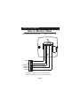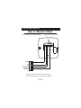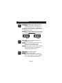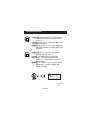
1
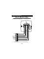
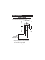
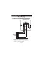
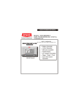
residential
THERMOSTAT
T1050
Digital
Thermostat
5+2 Day
PROGRAMMABLE
up to 2-heat
& 2-cool
HEAT
COOL
Control up to 2 heat & 2 Cool Stages
4 Settings Per Day
Self-prompting programming
Auto changeover
Separate weekday, Saturday
& Sunday programming
HEAT
PUMP
Back-Lit display
One For All Works with
Virtually All Equipment
5 minute Built-In
Compressor Protection
Non-Volatile memory
Dual setpoint with
adjustable deadband
Keypad lockout
‘O’ or ‘B’ Terminal
Display either F or C
Use with most Air Conditioning & Heating Systems including: 1 or 2 Stage
Electric Cooling & 2 Stage Gas Heating, Heat Pump, Electric or Hydronic Heat.
INSTALLATION
INSTRUCTIONS
Venstar Inc. 08/07
Table Of Contents
Step #1: Preparation
2
Step #2: Remove & Replace
Old Thermostat
3
Step #3: Wire Connections
4
Sample Wiring Diagrams
5
Step #4: Test Operation
12
Trouble Shooting
13
CAUTION
Follow Installation Instructions carefully.
DISCONNECT POWER TO THE HEATER AIR CONDITIONER BEFORE REMOVING
THE OLD THERMOSTAT AND INSTALLING
THE NEW THERMOSTAT.
WARNING
Venstar Inc. 08/07
P/N T1050
This device complies with Part 15 of the FCC rules.
Operation is subject to the following two conditions:
(1) This device may not cause harmful interference, and
(2) this device must accept any interference received,
including interference that may cause undesired operation.
Page 1
STEP #1
PREPARATION
Proper installation of the thermostat will be
accomplished by following these step by step
instructions. If you are unsure about any of
these steps, call a qualified technician for
assistance.
Assemble tools.
Flat Blade
Screwdriver
Wire cutter
& Stripper
Drill with 3/16
inch Drill Bit
(when not using
j-box)
Make sure your Heater/Air Conditioner is
working properly before beginning installation
of the thermostat.
Carefully unpack the thermostat. Save the
screws, wall anchors, and instructions.
Turn off the power to the Heating/Air
Conditioning system at the main fuse panel.
Most residential systems have a separate
breaker for disconnecting power to the furnace.
Page 2
STEP #2
REMOVE & REPLACE OLD THERMOSTAT
Remove the cover of the old thermostat.
If it does not come off easily check for
screws.
Loosen the screws holding the thermostat
base or subbase to the wall, and lift away.
Disconnect the wires from the old
thermostat. Tape the ends of the wires
as you disconnect them, and mark them
with the letter of the terminal for easy
reconnection to the new thermostat.
Keep the old thermostat for reference
purposes, until your new thermostat is
functioning properly.
Page 3
STEP #3
WIRE CONNECTIONS
If the terminal designations on your old
thermostat do not match those on the
new thermostat, refer to the chart below,
or the wiring diagrams that follow.
Wire from the
old thermostat
terminal marked
Function
G or F
Fan
Y1, Y or C
Cooling
W1, W or H
Heating
Install on the
new thermos tat
connector marked
G
Y1
W1,O,B
Rh, R, M, Vr, A
Power
C
Common
C*
R
O/b
Rev. Valve
W1,O,B**
Y2
2nd Stage Cool
Y2
W2
2nd Stage Heat
W2
* C may not be used on all systems.
** O/b is used if your system is a Heat Pump.
Page 4
Sample Wiring Diagrams
Gas or Electric Heat
5 Wire, 1 Stage Cooling, 1 Stage Gas Heat
Residential Gas or Electric Heat*,
Electric Cool, split systems & package
units
G
GAS VALVE
or
STRIP HEAT
W
COMPRESSOR
COMMON
C
FAN
Y
POWER
R
B
O
R G Y1 W2 W1 Y2 C
* If using first stage electric heat, this option must be
selected ON (see page 12, step 5 of Owner’s Manual).
Page 5
Sample Wiring Diagrams
Gas or Electric Heat
4 Wire, 1 Stage Cooling, 1 Stage Gas Heat
Residential Gas or Electric Heat*,
Electric Cool, split systems & package
units
FAN
G
COMPRESSOR
Y
GAS VALVE
or
STRIP HEAT
W
POWER
R
B
O
R G Y1 W2 W1 Y2 C
* If using first stage electric heat, this option must be
selected ON (see page 12, step 5 of Owner’s Manual).
Page 6
Sample Wiring Diagrams
Gas or Electric Heat
6 Wire, 2 Stage Cooling, 1 Stage Gas Heat
Residential two stage cooling with
Gas or Electric Heat*.
G
COMPRESSOR
COMMON
Y2
C
GAS VALVE
or
STRIP HEAT
2nd STAGE
COOLING
W
FAN
Y
POWER
R
B
O
R G Y1 W2 W1 Y2 C
* If using first stage electric heat, this option must be
selected ON (see page 12, step 5 of Owner’s Manual).
Page 7
Sample Wiring Diagrams
Gas or Electric Heat
6 Wire, 1 Stage Cooling, 2 Stage Heat
Residential & commercial 1 Stage Cooling,
with 2 Stage Gas or Electric Heat*
G
COMMON
W
2nd STAGE
HEATING
GAS VALVE
or
STRIP HEAT
W2
COMPRESSOR
C
FAN
Y
POWER
R
B
O
R G Y1 W2 W1 Y2 C
* If using first stage electric heat, this option must be
selected ON (see page 12, step 5 of Owner’s Manual).
Page 8
Sample Wiring Diagrams
Gas or Electric Heat
7 Wire, 2 Stage Cooling, 2 Stage Heat
Commercial Gas or Electric Heat *,
Electric Cool, split systems & package units
including Commercial Heat Pumps **
G
COMPRESSOR
COMMON
W
Y2
C
2nd STAGE
HEATING
GAS VALVE
or
STRIP HEAT
2nd STAGE
COOLING
W2
FAN
Y
POWER
R
B
O
R G Y1 W2 W1 Y2 C
* If using first stage electric heat, this option must be
selected ON (see page 12, step 5 of Owner’s Manual).
** Commercial heat pumps do not have the heat pump turned
ON in advanced setup (see page 11, step 3 of Owner’s Manual).
Page 9
Sample Wiring Diagrams
Heat Pump
5 Wire, 1 Stage Cooling, 1 Stage Heat-Heat Pump* with O or b reversing valve**.
Residential Heat Pumps, split systems & package units, with no auxiliary heat.
G
REVERSING VALVE**
O/B
COMPRESSOR
COMMON
C
FAN
Y
POWER
R
B
O
R G Y1 W2 W1 Y2 C
* This option must be selected ON during advanced setup
(see page 11, step 3 of Owner’s Manual).
** This option must be selected O or b during advanced setup
(see page 12, step 4 of Owner’s Manual).
Page 10
Sample Wiring Diagrams
Heat Pump
6 Wire, 1 Stage Cooling, 2 Stage Heat-Heat Pump* with O or b reversing valve**.
Residential Heat Pumps, split systems & package units, with auxiliary heat.
G
REVERSING VALVE**
O/B W2
COMPRESSOR
COMMON
C
FAN
Y
POWER
R
B
O
R G Y1 W2 W1 Y2 C
2nd STAGE
HEATING
* This option must be selected ON during advanced setup
(see page 11, step 3 of Owner’s Manual).
** This option must be selected O or b during advanced setup
(see page 12, step 4 of Owner’s Manual).
Page 11
STEP #4
TEST OPERATION
Turn the power on to the Heating/Air
Conditioning system.
Press the MODE button repeatedly until
the HEAT icon appears on the display.
Press the UP or DOWN buttons until the set
temperature is 10 degrees above room
temperature.
The HVAC unit should
energize in the heating mode.
Press the MODE button repeatedly until
the COOL icon appears on the display.
Press the UP or DOWN buttons until the set
temperature is 10 degrees below room
temperature.
The HVAC unit should
energize in the cooling mode.
NOTE: Most equipment has a time delay
of 5 minutes between cool cycles. This
feature is defeatable on the thermostat
(see page 13, step 8 of Owner's Manual).
Press the UP button until the setpoint is
equal to the room temperature. Press the
FAN button to Fan On. The fan should turn
on and run continuously.
Page 12
TROUBLESHOOTING
SYMPTOM: When using 4 wires (R, G, W, Y),
the air conditioning equipment tries
repeatedly to turn on, but cannot. At
times the display dims or disappears.
CAUSE: There is not enough power available
to "power share".
REMEDY: Connect a 250 ohm, 10 watt power
resistor at the furnace as shown below.
For Problem A/C
R
G
W
Y
C
For Problem Heat
R
TR300-10w
G
W
Y
C
TR300-10w
SYMPTOM: The air conditioning does not
attempt to turn on.
CAUSE: The compressor timer lockout may
prevent the air conditioner from
turning on, for a period of time.
REMEDY: See page 13 of the Owner's Manual
and configure step 8 to defeat the 5minute compressor lockout.
SYMPTOM: The display is blank.
CAUSE: Lack of proper power.
REMEDY: Make sure power is turned on to
the furnace and 24vac between R & W.
If C is used, 24vac between R & C.
Page 13
TROUBLESHOOTING
SYMPTOM: When controlling a residential heat
pump, and asking for cooling, the heat
comes on.
CAUSE: Heat pump is not selected "ON" in the
Advanced Setup.
REMEDY: See page 11 of the Owner's Manual
and configure step 3 to enable heat pump
operation.
SYMPTOM: When calling for cooling, both
the heat and cool come on.
CAUSE: The thermostat is configured to
control a heat pump and the HVAC
system is a "conventional" (non-heat
pump) system.
REMEDY: See page 11 of the Owner's Manual
and set step 3 to OFF to enable gas
electric operation.
STAR
T1050
c
FC
Tested to Comply
with FCC Standards
FOR HOME OR OFFICE USE
4Z95
P/N 88-610
Rev. 1
Page 14