1
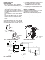
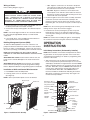
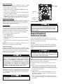
HOSS Series (Rev B)
Smart Series
Large Wall Heater
Installation, Operation & Maintenance Instructions
READ CAREFULLY - This manual provides instructions for the correct installation, safe use, and care of this product. Special attention should be directed to the warnings provided below which identify certain precautions and special instructions for safe and efficient installation and use. Studying these instructions first may save you considerable time and money later and keep your installation time to a minimum. If you are not familiar with electricity or feel uncomfortable in working with electricity, refer the installation of
this product to a licensed electrician or qualified person.
Table 1. Specifications
MODEL
HOSS4008
HOSS4004
HOSS4007
VOLTS
PHASE
WATTS
AMPS
MIN. SUPPLY
WIRE GAUGE
208
240
277
1
1
1
1800-4000
1800-4000
1800-4000
19.2
16.7
14.4
10
10
12
IMPORTANT INSTRUCTIONS
WARNING
WHEN USING ELECTRIC APPLIANCES, BASIC PRECAUTIONS SHOULD ALWAYS BE FOLLOWED TO REDUCE THE
RISK OF FIRE, ELECTRIC SHOCK, AND INJURY TO PERSONS, INCLUDING THE FOLLOWING:
1. Read all instructions before installing or using this heater.
2. This heater is hot when in use. To avoid burns, do not let
bare skin touch hot surfaces. Keep combustible materials,
such as furniture, pillows, bedding, papers, clothes, curtains, etc. at least 3 feet (0.9 m) from the front of the heater.
3. Extreme caution is necessary when any heater is used by or
near children or invalids and whenever the heater is left
operating and unattended.
4. Do not operate any heater after it malfunctions. Disconnect
power at service panel and have heater inspected by a qualified electrician before using.
!
9. A heater has hot and arcing or sparking parts inside. Do not
use it in areas where gasoline, paint, or flammable liquids
are used or stored.
10. Use this heater only as described in this manual. Any other
use not recommended by the manufacturer may cause fire,
electric shock, or injury to persons.
11. This heater is provided with a red alarm light that will illuminate ONLY if the heater has turned off as a result of overheating. If you see the light on, immediately turn the heater
OFF and inspect for any objects on or adjacent to the heater
that may have blocked the airflow or otherwise caused high
temperatures to have occurred. DO NOT OPERATE THE
HEATER WITH THE ALARM LIGHT ILLUMINATING.
5. Do not use outdoors.
12. This heater is intended for comfort heating applications and
not intended for use in special environments. Do not use in
damp or wet locations such as marine or greenhouse or in
areas where corrosive or chemical agents are present.
6. To disconnect heater, turn controls to OFF, and turn OFF
power to heater circuit at main disconnect panel.
13. When installing, see INSTALLATION INSTRUCTIONS for
additional warnings and precautions.
7.
14. For safe and efficient operation, and to extend the life of your
heater, keep your heater clean - See MAINTENANCE
INSTRUCTIONS.
Do not insert or allow foreign objects to enter any ventilation
or exhaust opening as this may cause an electric shock, fire,
or damage to the heater.
8. To prevent a possible fire, do not block air intake or exhaust
in any manner.
SAVE THESE INSTRUCTIONS
PPD 35950
06/12
5200-11092-000
INSTALLATION
INSTRUCTIONS
Installation of Back Box in New Construction
TO PREVENT HAZARD OF FIRE OR ELECTRICAL SHOCK,
DO NOT INSTALL WITHOUT BACK BOX.
To prevent a possible fire, injury to persons or damage to the
heater, adhere to the following:
TO PREVENT POSSIBLE DAMAGE TO POWER WIRING,
USE ONLY THE KNOCKOUTS PROVIDED IN BACK BOX
WITH LISTED CABLE CLAMP OR BUSHING.
1. Disconnect all power coming to heater at main service
panel before wiring or servicing.
2. All wiring procedures and connections must be in accordance with the National and Local Codes having jurisdiction
and the heater must be grounded.
Ground screw
Cable
clamp
Power supply cable
Lead wires (Blue)
3. Verify the power supply voltage coming to heater matches
the ratings as shown on the heater nameplate.
ON/OFF switch bracket
with switch and leads
CAUTION: ENERGIZING HEATER AT A VOLTAGE GREATER
THAN THE VOLTAGE PRINTED ON THE NAMEPLATE WILL
DAMAGE THE HEATER AND VOID THE WARRANTY AND
COULD CAUSE A FIRE.
4. CAUTION - High temperature, risk of fire, keep electrical
cords, drapery, furnishings, and other combustibles at least
3 feet (0.9 m) from front of heater. Do not install heater
behind doors, below towel racks, or in an area where it is
subject to being blocked by furniture, curtains or storage
materials. Hot air from the heater may damage certain fabrics and plastics.
Back Box
12” Min.
(305 mm)
12” Min.
(305 mm)
Nail or screw
(2 each side)
Figure 1 - Locating Back Box in New Construction
5. To reduce the risk of fire, do not store or use gasoline or
other flammable vapors and liquids in the vicinity of the
heater.
NOTE: If the finished wall surface is already up, follow instructions for “Installation of Back Box in Existing Construction”.
6. For wall mounting only with air discharge downward. Do
NOT install in floor, ceiling, upside down (air discharge
upward), or sideways.
1. Place the back box between two 16" (406 mm) center-tocenter wall studs at the desired mounting height but no
closer than 12" (305 mm) to adjacent wall or floor.
7. The following minimum clearances must be maintained:
NOTE: If wall studs are spaced greater than 16” on center,
additional framing supports may be necessary.
Bottom of heater to floor - 12” (305 mm).
Sides of heater to adjacent wall - 12” (305 mm).
2. Align back box such that the bottom and sides will be flush
with finished wall surface (top flange of back box should
protrude approximately 1/2" (13 mm) from finished wall
surface (You must know the thickness of the finished wall
when installing).
Top of heater to ceiling - 36” (915 mm).
8. Do not operate the heater without the grille installed.
9. Do not use this heater for dry out as the paint, plaster, sawdust and drywall sanding dust will permanently damage the
heater and must be kept out of the heater.
3. Secure the back box in position with wood screws or nails as
shown in Figure 1.
The heater is designed for recessed installation in 2” x 4”
(50 mm x 101 mm) studs or larger wall sections using the back
box provided. The heater may be wired with standard building
wire (60°C). Refer to “Specifications” and heater nameplate for
correct supply voltage and wire size.
4. Run a power supply cable into the knockout area in the upper
right hand corner of the back box (see Figure 1). All wiring
must be in accordance with National and Local Electrical
Codes. Refer to Specifications for correct wire size.
5. Remove ON/OFF switch bracket by loosening two screws on
the right side.
NOTE: The optimum mounting height for this heater is 18” to 24”
(450 mm to 600 mm) from floor to bottom of back box. DO NOT
install closer than 12” (305 mm) from the floor.
6. Install a cable clamp in the knockout in the top of the back
box.
7. Insert power supply cable through cable clamp, allowing at
least 6" (152 mm) of leads to extend inside the back box.
Connect the blue lead wires of ON/OFF switch to the supply
wire leads using wire connectors (see Figure 3, Wiring
Diagram).
NOTE: If power supply is provided by standard non-metallic
sheathed cable (Romex) and the supply voltage is 240 or 208
volts (two power wires), the white wire color must be changed
using black electrical tape to comply with the NEC. White is only
allowed for a Neutral conductor.
8. Connect building ground conductor to the back box using the
green screw located in the inside top of the back box.
9. Secure ON/OFF switch bracket in place by tightening screws.
2
Installation of Back Box in
Existing Construction
6. Connect building ground conductor to the back box using the
green screw located in the inside top of the back box.
1. Provide a wall opening 14-1/2" (362 mm) wide by 18-1/2"
(470 mm) high at the desired mounting height, but no closer
than 12" (305 mm) from floor or adjacent wall. (See Figure 2.)
Locate so at least one side of opening is at wall stud.
7.
Secure ON/OFF switch bracket in place by tightening
screws.
8. Insert back box in wall opening being careful not to damage
the supply wiring. Secure the back box in place with wood
screws or nails.
2. Run a power supply cable into the knockout area in the upper
right hand corner of the wall opening (see Figure 2). All
wiring must be in accordance with National and Local
Electrical Codes. Refer to Specifications for correct wire size.
Installation of Heater Assembly
Carefully position the heater assembly, with fan on top, and element on bottom into the back box (see Figure 4).
3. Remove ON/OFF switch bracket by loosening two screws on
the right side.
NOTE: The heater assembly must be carefully positioned to
ensure the wires and wire connector are not trapped between
the heater assembly and the back box.
4. Install a cable clamp in the knockout in the top of the back
box.
Once the heater assembly is positioned correctly in the back
box, fasten securely using the four screws provided, one in each
corner (see Figure 4).
5. Insert power supply cable through cable clamp, allowing at
least 6" (152 mm) of leads to extend inside the back box.
Connect the blue lead wires of ON/OFF switch to the supply
wire leads using wire connectors (see Figure 3, Wiring
Diagram).
NOTE: If power supply is provided by standard non-metallic
sheathed cable (Romex) and the supply voltage is 240 or 208
volts (two power wires), the white wire color must be changed
using black electrical tape to comply with the NEC. White is only
allowed for a Neutral conductor.
Mounting Screw
Locations
12” Min.
(305 mm)
12” Min. Cable
(305 mm)
clamp
14 1/2” Min.
Ground
(362 mm)
screw
Power supply cable
Lead wires (Blue)
ON/OFF switch
bracket with switch
and leads
Back Box
Mounting Screw
Locations
Nail or screw
(2 each side)
Figure 4 - Installation of Heater Assembly
Figure 2 - Locating Back Box in Existing Construction
ON/OFF SWITCH
L2/N
L2/N
L2/N
*BLACK
L1
L1
G
G
*BLUE
RED
L1
BLACK
BLUE
GREEN
*BLACK AND *BLUE LEAD WIRES ARE
IDENTIFIED WITH WHITE TAPE AT EACH
STRIPPED END TO INDICATE THAT THE
NEUTRAL FOR THE 277V MODELS ARE
TO BE CONNECTED TO THESE LEADS.
BLACK
G
W4
Transformer
W5
W6
W6
VDR1
BLACK
RED
BLACK
E1
THERMISTOR
E2
BLUE
E3
S1
S2
A
FAN-N
CONTROL BOARD
YELLOW
LIGHT
FAN-A
B
RED JUMPER WIRE FOR
BUILDING MANAGEMENT
SYSTEM CONNECTION
DATA CABLE
MANUAL
RESET
RED
MOTOR LEAD
MOTOR
MOTOR LEAD
Field Connections
ELEMENT
Figure 3 - Wiring Diagram
3
Wiring of Heater
• TOP - Align the screw bosses on the back of the plastic
cover with the second hole down from the top of the back
box and attach it with the two screws provided.
Refer to Wiring Diagram, Figure 4
• BOTTOM - Align the screw bosses on the back of the
second plastic cover with holes at the bottom of the back
box that are just above the fan deck mounting screws and
attach it with two screws provided.
POWER SUPPLY VOLTAGE MUST BE THE SAME AS
HEATER VOLTAGE RATING SHOWN ON HEATER NAMEPLATE. CONNECTING TO A VOLTAGE IN EXCESS OF
NAMEPLATE RATING WILL DAMAGE HEATER AND VOID
WARRANTY. ALL CONNECTIONS MUST BE MADE WITH
APPROPRIATELY SIZED LISTED WIRE CONNECTORS.
3. Position the grille in front of the heater assembly, extend the
control wire connector from the heater assembly to the
matching connector from the back of the electronic control,
behind the grille. The connector is keyed so it will fit only one
way.
1. Connect the black (L1) heater pigtail from ON/OFF switch to
the black power lead on the heater assembly.
NOTE: Press the connector gently and firmly, but do not force,
making sure the clip on the connector engages.
2. Connect the red (L2) heater pigtail to the other black power
lead.
NOTE: L2/N heater pigtail is white for 277 volt model and must
be connected (through ON/OFF Switch) to a white Neutral
supply lead.
4. Install the front cover by hooking the (2) tabs on top and
bottom plastic covers on one side then rotating the front
cover into place making sure that all four tabs are snapped
into the grille.
3. If not already done, connect building ground conductor to
green ground screw in heater back box.
NOTE: Use caution when installing the grille to avoid trapping
the control wire in between the grille and heater assembly.
Building Management Systems (BMS)
OPERATION
INSTRUCTIONS
To utilize the BMS capabilities of this unit, remove the red
jumper wire between terminals A and B on the control terminal
board ( see figure 3, wiring diagram). Connect two wires from a
dry contact (no voltage) in the BMS system to terminals A and B.
Initial Setup Instructions (Performed by Installer)
NOTE: DO NOT REMOVE THE RED JUMPER UNLESS
CONTROL BY A BUILDING MANAGEMENT SYSTEM IS BEING
USED.
NOTE: After installation, the installer should perform the following procedures to ensure proper operation of the heater. See
“Customizing Heater Settings” for details on programming other
functions of the heater.
When BMS takes control, heater functions will not work, the
touch screen is locked, BMS light on the heater touchscreen
blinks.
1. Switch the power on at the main circuit panel. When the
heater is first powered up the buzzer beeps for one second
and displays all indicators in high luminance and the POWER
button in half blue luminance for 3 seconds, then the unit will
turn OFF. When OFF, only the POWER button illuminates in
orange color in half luminance and all other buttons and
icons will be OFF. When OFF, if the POWER button is
touched, all 4 buttons will illuminate indicating the heater is
ON and the control panel is powered up. See Figure 6 for
Control Panel layout details.
When BMS releases control, heater functions are available,
heater resumes operating at previously programmed settings.
Refer to Operations Manual for programming options and details.
Installation of Grille and Control Wire Connector
1. Push ON/OFF switch into ON position.
2. Install (2) plastic covers on back box as follows:
(See Figure 5)
NOTE: Both top and bottom plastic covers are identical.
Wire Connector
Day indicator
(also used when programming custom periods)
Plastic Cover
Centigrade /
Fahrenheit indicator
Heat control
indicator
Temperature
Fan Speed
indicator
Building Management
System indicator
Automatic mode
indicator
Lock Out indicator
Nightlight
indicator
Time
Tab
Screws
Plastic Cover
Down Button
Hold indicator
Time periods:
1- Wake up
2- Daytime
3- Evening
4- Sleep
Up Button
Grille
Power Button
Figure 5 - Installation of Grille Assembly
Figure 6 - Control Panel
4
Mode Button
2. Set Day and Time:
3. Touch MODE button again to program the MINUTES for
Period 1. Touch the UP or DOWN buttons to set MINUTES.
NOTE: For the following setup procedures, the display will automatically save the setting after a 30 second pause and return to
the previous operating setting. If this occurs, start back at
Step a of the Set Day and Time procedure.
4. Touch MODE button again to start programming the
TEMPERATURE for Period 1 (Wake Up). Touch the UP or
Down buttons to set temperature for Wake Up.
5. Touch the MODE button again to move to Period 2 and follow
steps 2 through 4 for each of the remaining periods. Once
the Weekdays (Monday through Friday) are set, touching the
MODE button again will move to the Weekend settings.
Follow steps 2 through 4 again for the weekend settings.
a. Simultaneously touch and hold the UP button and DOWN
button for 1.5 seconds. A beep will sound and the Day indicator at the top of the display will flash (the buttons on the
display respond to touch, not pressure).
NOTE: If user touches the POWER button at any point during
setup procedure, the display will automatically save settings and
return to the previous operating setting.
6. Once the previous steps are complete, touch the MODE button once more to lock the settings or wait 30 seconds and
the unit will lock the settings automatically. Once the settings
have been locked the unit will begin normal operation.
b. Using the UP or DOWN buttons, adjust to appropriate DAY
of week.
Hold Mode (Vacation Setting)
c. Touch the MODE button. AM / PM indicator will flash. Use
the UP and DOWN buttons to set appropriate time.
AM / PM will change automatically once you pass 12:00.
The HOLD mode overrides the programmed settings and is useful when a constant temperature needs to be maintained for
comfort or can be set at a lower temperature for times when the
area is unoccupied for long periods (vacation setting) or if freeze
protection is needed in colder climates.
d. Touch the MODE button, MINUTES will flash. Use the UP
and DOWN buttons to set MINUTES to the appropriate
time.
1. Touch MODE button once to activate the display and touch
the MODE button again until the HOLD indicator appears.
e. After the last parameter is set, touch the MODE button to
lock in your settings.
2. Touch the Up or Down buttons to set temperature to your
“Hold” temperature. During HOLD mode, default settings
along with the automatic rotation of the 4 periods will be disabled. The heater will operate from the current setting, where
the setpoint can be adjusted.
3. Once the installer has performed the initial setup, power
down the unit by touching the POWER button if no other programming will be done at this time.
NOTE: The unit is programmed with default time and temperature settings for the Automatic Mode (see below). If these settings are satisfactory, then skip “Programming the Thermostat for
Automatic Mode” and continue to the other programmable
options under “Customizing Heater Settings”.
NOTE: HOLD mode setting will not be saved after exiting.
Default settings for Automatic Mode:
Ventillation Mode
Period
Time
Setpoint
1. Wake Up
6:00 AM
70°F (21°C)
2. Daytime
8: 00 AM
62°F (17°C)
3. Evening
6:00 PM
70°F (21°C)
4. Sleep Time
10:00 PM
62°F (17°C)
3. To exit out of the HOLD mode, the user has to press the
MODE button.
This heater also has the option to use as a FAN ONLY device. Heat
will not be produced, but the ventilator fan will operate to provide a
nice gentle breeze to circulate the air.
Touch the MODE button until you see the FAN icon illuminate and flash.
Use the Up or Down buttons to increase or decrease the fan speed.
NOTE: The fan icon will flash for 3 seconds. After 3 seconds, the
heater will enter Fan Only Operation. Touching the MODE button
again will switch the heater into another operation.
Customizing Heater Settings
The heater has three modes of operation, Automatic (Heat)
Mode, Ventilation Mode, and Hold Mode with five user
programmable options, 7 Day Programmable Thermostat,
Lockout Setting, Volume Adjustment, Centigrade/Fahrenheit, and
a Nightlight.
Celsius / Fahrenheit Indication
The default temperature scale for the heating unit is Fahrenheit.
To change the temperature scale, simultaneously touch and hold
the MODE and DOWN buttons for 1.5 seconds. Notice the C
indicator illuminates. Touch both buttons again to change back
to the F (Fahrenheit) scale.
NOTE: For the following setup procedures, the display will automatically save the setting after a 30 second pause and return to
the previous operating setting. If this occurs, start back at Step 1
of the procedure.
Lock Out Feature
Touch and hold the POWER and DOWN buttons simultaneously
for 1.5 seconds. Notice that the Padlock symbol will be visible.
Touch and hold both buttons again to toggle Padlock symbol ON
or Padlock symbol OFF.
Programming the Thermostat for Automatic Mode
The 7 day programmable thermostat can be customized for two
categories, Weekdays (Monday-Friday) and Weekends (Saturday
& Sunday). Each category has 4 periods, see the Default settings above for an example. Set a start time and temperature for
each period:
NOTE: With the Padlock symbol ON, the unit is locked (the
POWER button is functional, the normal functions of the other
buttons are disabled).
Night Light Operation
1. Simultaneously touch and hold the POWER and MODE
buttons for 1.5 seconds. MON through FRI will display with
the hour and Period 1. This is your wake-up time.
Touch and hold MODE and UP Buttons simultaneously for 1.5
seconds. Notice that the NIGHT LIGHT (Light bulb) indicator will
be visible and the backlight will illuminate at 100% brightness.
Touch both buttons again and the NIGHT LIGHT indicator and
backlight will turn OFF.
2. Touch MODE button once to start programming the HOUR
for Period 1 (Monday through Friday). Touch either the UP or
Down buttons to set the hour for START time.
5
Beep Volume Control
There are three settings for the audible beep, 2=HIGH , 1=LOW,
0=OFF. To adjust the audible beep, follow these instructions.
ON/OFF
Switch
1. Make sure the display is OFF.
2. Simultaneously touch the POWER and MODE buttons until
either a 2, 1 or 0 is displayed.
Red Warning
Light
3. Press the Up or Down Buttons to make a selection between
2 (HIGH), 1 (LOW) or 0 (OFF).
4. After the desired volume is set, touch the POWER button or
MODE button to exit the volume adjustment menu; or do not
touch any button for 30 seconds to lock in your selection.
Manual Reset
Safety Limit
Restore Factory Settings
(Display must be OFF, POWER button is amber color) Press the
MODE and DOWN buttons simultaneously for 1.5 seconds, the
beeper sounds a beep and factory settings are restored. See
“Default Settings For Automatic Mode”.
Figure 8 Reset Button Location
Remote Control
CAUTION - DO NOT CONTINUE TO ATTEMPT TO USE THE
HEATER IF THE SAFETY CONTROL REPEATEDLY OPERATES AFTER BEING RESET. TO DO SO COULD PERMANENTLY DAMAGE THE HEATER OR CREATE A FIRE OR
SAFETY HAZARD.
The remote control will control your heater from a distance no
more than 20 feet away from the unit. When pointing the device
it must be in line of sight in order to operate correctly. The
remote will not program your heater. It will only turn the heater
ON or OFF and adjust the set temperature UP or DOWN.
MAINTENANCE
INSTRUCTIONS
There are only four buttons that are active:
1. Power ON ON button.
2. Power OFF OFF button.
3. DOWN button to lower the displayed temperature (located
bottom left)
Your heater is designed for years of trouble-free operation and
requires no special maintenance other than occasional cleaning.
The motor is permanently lubricated.
4. UP button to raise the displayed temperature (located bottom
right)
Cleaning
NOTE: Should you misplace your remote; the operation of your
heater can be controlled at the heater display.
At least once each year (or more often in dirty environments),
the heater should be cleaned to remove dust and other foreign
material which has collected during the heating season, as
follows:
Operational Notice
This heater is equipped with a manual-reset safety limit control
that will automatically turn off the heater if it overheats to prevent
a fire. A red warning light will illuminate (visible through the
grille) to alert that this control has activated. See Figure 8 for
the location of these devices.
THE OUTSIDE SURFACES MAY BE CLEANED WITH MILD
DETERGENT AND A DAMP CLOTH BY THE USER.
ALL OTHER SERVICING SHOULD BE PERFORMED BY AN
ELECTRICIAN OR QUALIFIED PERSON
THE ACTIVATION OF THE SAFETY LIMIT CONTROL AND
RED WARNING LIGHT OCCURS WHEN THE HEATER OVERHEATS. CHECK HEATER TO MAKE SURE IT IS NOT
BLOCKED – IF SO, REMOVE THE BLOCKAGE. IF THERE IS
NO BLOCKAGE, IT IS RECOMMENDED THAT THE HEATER
BE INSPECTED BY A REPUTABLE ELECTRICIAN OR
REPAIR SERVICE TO ENSURE THE HEATER IS NOT
DAMAGED. DO NOT CONTINUE TO USE HEATER IF IT
REPEATEDLY CYCLES OFF ON THIS SAFETY LIMIT.
1. Turn power OFF at main switch.
NOTE: With grille removed, the ON/OFF switch located in upper
right corner of heater may be used to turn off power to heater
during cleaning and servicing (see Figure 8).
2. Remove front grille by removing the four screws in each
corner.
3. Use vacuum cleaner with brush attachment to remove dust
and dirt that has accumulated in heater (especially around
element and blower blade). Do not use water or any cleaners
to clean heater components.
TO RESET SAFETY LIMIT (SEE FIGURE 8)
The manual reset button is located behind the front grille above
the element on the left side. Once the heater has cooled, push
the reset button through the grille. The heater should return to
normal operation.
4. Replace grille.
5. Wipe grille clean with a damp cloth. DO NOT use waxes or
any cleaners that leave a residue since these may discolor
during heater operation.
6. Turn the main line switch ON at the switch panel to restore
power to heater. The heater is now ready for another season
of operation.
DO NOT TAMPER WITH OR BYPASS ANY SAFETY LIMITS
INSIDE HEATER.
6
REPAIR PARTS
4
5
8
7
15
6
1
11
12
2
10
13
9
8
Repair Parts List
Description
HTWH4008
208V 4000W
Part Number
HTWH4004
240V 4000W
HTWH4007
277V 4000W
Quantity
Painted Grille
Northern White
Statuary Bronze
Navajo White
2501-11022-000
2501-11022-001
2501-11022-002
2501-11022-000
2501-11022-001
2501-11022-002
2501-11022-000
2501-11022-001
2501-11022-002
1
1
1
2
Back Box Assembly
1203-2015-000
1203-2015-000
1203-2015-000
1
3
Parts Bag (not shown)
1205-2020-002
1205-2020-002
1205-2020-002
1
4
Data Cable
1426-11010-001
1426-11010-001
1426-11010-001
1
5
Control Board (power board)
1414-11043-000
1414-11043-000
1414-11043-001
1
6
Thermistor
5262-11006-000
5262-11006-000
5262-11006-000
1
7
Touch Pad / Bezel Assembly
1016-11199-000
1016-11199-000
1016-11199-000
1
8
Plastic Cover (top and bottom identical)
Northern White
1402-2120-002
Statuary Bronze
1402-2120-001
Navajo White
1402-2120-000
1402-2120-002
1402-2120-001
1402-2120-000
1402-2120-002
1402-2120-001
1402-2120-000
1
1
1
9
Element Assembly
1802-11005-000
1802-11005-001
1802-11005-002
1
10
Safety Limit - Manual
4520-2027-000
4520-2027-000
4520-2027-000
1
11
Fan Motor
3900-2002-522
3900-2002-522
3900-2002-523
1
12
Fan Blade
490030103
490030103
490030103
1
13
Fan Delay
410074000
410074000
410074000
1
14
Indicator Light (not shown)
3510-2017-005
3510-2017-005
3510-2017-005
1
15
ON/OFF Assembly
5216-2008-000
5216-2008-000
5216-2008-000
1
Ref
No.
1
7
LIMITED WARRANTY
All products manufactured by Marley Engineered Products are warranted against defects in workmanship and materials for one year from date of installation, except
heating elements which are warranted against defects in workmanship and materials for five years from date of installation. This warranty does not apply to damage from
accident, misuse, or alteration; nor where the connected voltage is more than 5% above the nameplate voltage; nor to equipment improperly installed or wired or
maintained in violation of the product’s installation instructions. All claims for warranty work must be accompanied by proof of the date of installation.
The customer shall be responsible for all costs incurred in the removal or reinstallation of products, including labor costs, and shipping costs incurred to return products to
Marley Engineered Products Service Center. Within the limitations of this warranty, inoperative units should be returned to the nearest Marley authorized service center
or the Marley Engineered Products Service Center, and we will repair or replace, at our option, at no charge to you with return freight paid by Marley. It is agreed that such
repair or replacement is the exclusive remedy available from Marley Engineered Products.
THE ABOVE WARRANTIES ARE IN LIEU OF ALL OTHER WARRANTIES EXPRESSED OR IMPLIED, AND ALL IMPLIED WARRANTIES OF MERCHANTABILITY AND
FITNESS FOR A PARTICULAR PURPOSE WHICH EXCEED THE AFORESAID EXPRESSED WARRANTIES ARE HEREBY DISCLAIMED AND EXCLUDED FROM THIS
AGREEMENT. MARLEY ENGINEERED PRODUCTS SHALL NOT BE LIABLE FOR CONSEQUENTIAL DAMAGES ARISING WITH RESPECT TO THE
PRODUCT, WHETHER BASED UPON NEGLIGENCE, TORT, STRICT LIABILITY, OR CONTRACT.
Some states do not allow the exclusion or limitation of incidental or consequential damages, so the above exclusion or limitation may not apply to you. This warranty gives
you specific legal rights, and you may also have other rights which vary from state to state.
For the address of your nearest authorized service center, contact Marley Engineered Products in Bennettsville, SC, at 1-800-642-4328. Merchandise returned to the factory must be accompanied by a return authorization and service identification tag, both available from Marley Engineered Products. When requesting return authorization,
include all catalog numbers shown on the products.
HOW TO OBTAIN WARRANTY SERVICE AND
WARRANTY PARTS PLUS GENERAL INFORMATION
1. Warranty Service or Parts
2. Purchase Replacement Parts
3. General Product Information
1-800-642-4328
1-800-654-3545
www.marleymep.com
Note: When obtaining service always have the following:
1. Model number of the product
2. Date of manufacture
3. Part number or description
470 Beauty Spot Rd. East
Bennettsville, SC 29512 USA