1
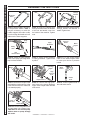
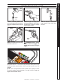
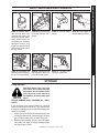
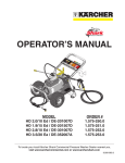
OPERATOR’S MANUAL
MODEL
DE-201007D
DE-201507D
DE-301007D
DE-352007A
ORDER #
1.106-061.0
1.106-062.0
1.106-063.0
1.106-064.0
To locate your local Shark Commercial Pressure Washer Dealer nearest you,
visit www.shark-pw.com
8.919-015.0
CONTENTS
Important Safety Information ................................................................3-4
Component Identification ......................................................................... 5
Assembly Instructions .............................................................................. 6
Operating Instructions.............................................................................. 7
Applying Detergents & General Cleaning Techniques ............................. 8
Shut Down and Clean-Up ........................................................................ 9
Storage .................................................................................................... 9
Troubleshooting ..................................................................................... 10
Preventative Maintenance ..................................................................... 11
Oil Change Record ................................................................................ 11
Exploded View ....................................................................................... 12
Exploded View Parts List ..................................................................13-14
Hose and Spray Gun Assembly ............................................................. 15
Unloader Exploded View and Parts List................................................. 16
Pump Exploded View and Parts List .................................................17-18
Specifications......................................................................................... 19
Warranty ................................................................................................ 20
Model Number ______________________________
Serial Number ______________________________
Date of Purchase ____________________________
The model and serial numbers will be found on a decal attached
to the pressure washer. You should record both serial number and
date of purchase and keep in a safe place for future reference.
2
9.800-085.0 • 8.919-015.0 • Rev. 01/11
Thank you for purchasing this Pressure Washer.
We reserve the right to make changes at any time
without incurring any obligation.
Owner/User Responsibility:
The owner and/or user must have an understanding of
the manufacturer’s operating instructions and warnings
before using this pressure washer. Warning information
should be emphasized and understood. If the operator
is not fluent in English, the manufacturer’s instructions
and warnings shall be read to and discussed with
the operator in the operator’s native language by the
purchaser/owner, making sure that the operator comprehends its contents.
Owner and/or user must study and maintain for future
reference the manufacturers’ instructions.
The operator must know how to stop the machine
quickly and understand the operation of all controls.
Never permit anyone to operate the engine without
proper instructions.
This manual should be considered a permanent
part of the machine and should remain with it if
machine is resold.
When ordering parts, please specify model and
serial number. Use only identical replacement
parts.
This machine is to be used only by trained operators.
IMPORTANT SAFETY
INFORMATION
WARNING: To reduce the risk of
injury, read operating instructions carefully before using.
1. Read the owner's manual
thoroughly. Failure to follow
instructions could cause malfunction of the machine and
READ OPERATOR’S
MANUAL THOROUGHLY
result in death, serious bodily
PRIOR TO USE.
injury and/or property damage.
2.
Know how to stop the
machine and bleed pressure quickly. Be thoroughly
familiar with the controls.
3. Stay alert — watch what you are doing.
4. All installations must comply with local codes. Contact your electrician, plumber, utility company or the
selling distributor for specific details. If your machine
is rated 250 volts or less, single phase will be provided with a ground fault circuit interrupter (GFCI).
If rated more than 250 volts, or more than single
phase this product should only be connected to a
power supply receptacle protected by a GFCI.
DANGER: Improper connection of the equipment-grounding conductor can result in a risk
of electrocution. Check with a qualified electrician or service personnel if you are in doubt as
to whether the outlet is properly grounded. Do
not modify the plug provided with the product
- if it will not fit the outlet, have a proper outlet
installed by a qualified electrician. Do not use
any type of adaptor with this product
WARNING: Keep wand, hose, and
water spray away from electric
wiring or fatal electric shock may
result.
5. To protect the operator from
electrical shock, the machine
KEEP WATER
must be electrically grounded.
SPRAY AWAY FROM
It is the responsibility of the
ELECTRICAL WIRING.
owner to connect this machine
to a UL grounded receptacle of proper voltage and
amperage ratings. Do not spray water on or near
electrical components. Do not touch machine with
wet hands or while standing in water. Always disconnect power before servicing.
WARNING
WARNING
RISK OF EXPLOSION:
DO NOT SPRAY
FLAMMABLE
LIQUIDS.
PRESSURE WASHER OPERATOR’S MANUAL
INTRODUCTION & IMPORTANT SAFETY INFORMATION
WARNING: Flammable liquids
can create fumes which can ignite, causing property damage
or severe injury.
WARNING: Risk of explosion —
Do not spray flammable liquids.
6.
Do not allow acids,
caustic or abrasive fluids to pass through the
pump.
7. Never run pump dry or leave spray gun closed
longer than 1-2 minutes.
8. Keep operating area clear of all persons.
WARNING
USE PROTECTIVE
EYE WEAR
AND CLOTHING
WHEN OPERATING
THIS EQUIPMENT.
9.800-085.0 • 8.919-015.0 • Rev. 01/11
WARNING: High pressure spray
can cause paint chips or other
particles to become airborne
and fly at high speeds. To avoid
personal injury, eye, hand and
foot safety devices must be
worn.
9. Eye, hand, and foot protection must be worn when
using this equipment.
3
PRESSURE WASHER
OPERATOR’S MANUAL
IMPORTANT SAFETY INFORMATION
WARNING
WARNING: Grip cleaning wand
securely with both hands before
starting. Failure to do this could
result in injury from a whipping
wand.
TRIGGER GUN KICKS
BACK - HOLD WITH
BOTH HANDS
WARNING
RISK OF INJECTION
OR SEVERE INJURY
TO PERSONS. KEEP
CLEAR OF NOZZLE.
14. Inlet water must be clean fresh water and no hotter
then 90°F.
15. Manufacturer will not be liable for any changes
made to our standard machines or any components
not purchased from us.
16. The best insurance against an accident is precaution and knowledge of the machine.
WARNING
WARNING: High pressure developed by these machines will
cause personal injury or equipment damage. Keep clear of
nozzle. Use caution when operating. Do not direct discharge
stream at people, or severe injury or death will result.
10. To reduce the risk of injury, close supervision is
necessary when a machine is used near children.
Do not allow children to operate the pressure
washer. This machine must be attended during
operation.
11. Never make adjustments on machine while in operation.
12. Be certain all quick coupler fittings are secured
before using pressure washer.
RISK OF INJURY
FROM FALLS WHEN
USING LADDER.
WARNING: Be extremely careful
when using a ladder, scaffolding
or any other relatively unstable
location. The cleaning area
should have adequate slopes
and drainage to reduce the possibility of a fall due to slippery
surfaces.
17. Do not overreach or stand on unstable support.
Keep good footing and balance at all times.
18. Do not operate this machine when fatigued or under
the influence of alcohol, prescription medications,
or drugs.
Follow the maintenance instructions
specified in the manual.
WARNING: Protect machine from
freezing.
13. To keep machine in best
operating conditions, it is
important you protect machine
from freezing. Failure to protect
machine from freezing could
PROTECT FROM
FREEZING
cause malfunction of the
machine and result in death,
serious bodily injury, and/or property damage. Follow storage instructions specified in this manual.
WARNING
4
9.800-085.0 • 8.919-015.0 • Rev. 01/11
Detergent
Injector
Water Supply
(not included)
Pump
Protector
Pressure
Nozzle
Quick
Coupler
Unloader
Soap
Nozzle
On/Off
Switch
Wand
Hanger
Pump
Safety
Latch
Detergent
Bucket (not
included)
PRESSURE WASHER OPERATOR’S MANUAL
COMPONENT IDENTIFICATION
Garden Hose
(not included)
GFCI
Spray Gun
and Wand
Pump — Develops high pressure.
Spray Gun — Controls the application of water and
detergent onto cleaning surface with trigger device.
Includes safety latch.
Detergent Injector — Allows you to siphon and mix
detergents when used with a soap nozzle.
Wand — Must be connected to the spray gun.
Unloader — Safety device that relieves pressure when
spray gun trigger is closed.
High Pressure
Hose
High Pressure Hose — Connect one end to water
pump discharge nipple and the other end to spray
gun.
Pump Protector — Cycles fresh cool water through
pump when recirculating water reaches 140°F.
GFCI — Ground fault circuit interrupter trips when
voltage leaks to ground.
Note: If trigger on spray gun is released for more
than 2 minutes, water will leak from valve. Warm water will discharge from pump protector onto floor.
This system prevents internal pump damage.
5
9.800-085.0 • 8.919-015.0 • Rev. 01/11
PRESSURE WASHER
OPERATOR’S MANUAL
ASSEMBLY INSTRUCTIONS
Carriage
Bolt
Handle
Alignment
Holes
Bolts
Hose/Gun
Storage
Bracket
Nut
Nut
Frame
Assy.
Studs
STEP 1: Attach handle to the frame
of the pressure washer. Note: It
may be necessary to move the
handle supports from side to side
in order to align the handle so it will
slide over the frame supports.
STEP 2: Insert the carriage bolt
through the holes from the outside
of the unit and attach a nut from
the inside of the machine. Tighten
nuts.
Spray
Gun
Safety
Latch
Spray
Gun/Wand
STEP 3: Attach the spray gun/hose
storage handle, and bracket to
handle. Tighten nuts.
Pressure
Nozzle
Wand
Coupler
Nozzle Extension
High
Pressure Hose
STEP 4: Attach the high pressure
hose to the spray gun using teflon
tape on hose threads.
Pressure
Nozzle
STEP 5: Attach nozzle extension
to spray gun/wand. Tighten both
by hand.
Pump
Discharge
Nipple
Wand Coupler
STEP 6: Pull the spring-loaded
collar of the wand coupler back
to insert your choice of pressure
nozzle.
Cold
Water
Source
High
Pressure
Hose
Wand
Collar
STEP 7: Release the coupler collar
and push the nozzle until the collar
clicks. Pull the nozzle to make sure
it is seated properly.
Coupler Collar
STEP 8: Connect the high pressure hose to the pump discharge
nipple. Push coupler collar forward
until secure.
Pump
Water Inlet
Garden Hose
6
STEP 10: Connect the garden hose
to pump water inlet. Inspect inlets.
CAUTION: Do not run the pump
without water or pump damage
will result.
9.800-085.0 • 8.919-015.0 • Rev. 01/11
Garden
Hose
STEP 9: Connect garden hose to
the cold water source.
Cold
Water
Source
Garden
Hose
STEP 1: Connect garden hose
to the cold water source and turn
water on completely. Never use hot
water.
STEP 2: Trigger the spray gun to
eliminate trapped air then wait for
a steady flow of water to emerge
from the spray nozzle.
On/Off
Switch
STEP 3: Connect to appropriate
power supply. Push reset button
on GFCI.
PRESSURE WASHER OPERATOR’S MANUAL
OPERATING INSTRUCTIONS
Safety
Latch
STEP 4: Turn machine on by turning
switch at top of motor.
WARNING! Never replace
nozzles without engaging the
safety latch on the spray gun
trigger.
NOZZLES
The five color-coded quick connect nozzles provide a wide array of
spray widths from 0° to 40° and are easily accessible when placed in the
convenient rubber nozzle holder, which is provided on the front of the
machine.
NOTE: For a more gentle rinse, select the white 40° or green 25° nozzle.
To scour the surface, select the yellow 15° or red 0° nozzle. To apply detergent select the black nozzle.
7
9.800-085.0 • 8.919-015.0 • Rev. 01/11
PRESSURE WASHER
OPERATOR’S MANUAL
DETERGENTS & GENERAL CLEANING TECHNIQUES
WARNING
WARNING: Some detergents
may be harmful if inhaled or
ingested, causing severe nausea, fainting or poisoning. The
harmful elements may cause
property damage or severe
injury.
STEP 1: Connect detergent injector to discharge nipple
on machine. Connect high pressure hose to injector
with quick coupler. (Check to make sure locking coupler
sleeves are in proper position before applying water
pressure).
Detergent
Injector
Discharge
Nipple
Quick
Coupler
THERMAL PUMP PROTECTION
If you run the motor on your pressure washer for 3-5
minutes without pressing the trigger on the spray gun,
circulating water in the pump can reach high temperatures. When the water reaches this temperature, the
pump protector engages and cools the pump by discharging the warm water onto the ground. This thermal
device prevents internal damage to the pump.
CLEANING TIPS
Pre-rinse cleaning surface with fresh water. Place detergent suction tube directly into cleaning solution and apply
to surface at low pressure (for best results, limit your work
area to sections approximately 6' square and always
apply detergent from bottom to top). Allow detergent to
remain on surface 1-3 minutes. Do not allow detergent
to dry on surface. If surface appears to be drying, simply
wet down surface with fresh water. If needed, use brush
to remove stubborn dirt. Rinse at high pressure from top
to bottom in an even sweeping motion keeping the spray
nozzle approximately 1' from cleaning surface. Use overlapping strokes as you clean and rinse any surface. For
best surface cleaning action spray at a slight angle.
Recommendations:
Filter
STEP 2: Use detergent designed
specifically for pressure washers.
Household detergents could damage the pump. Prepare detergent
solution as required by the manufacturer. Fill a container with pressure washer detergent. Place the
filter end of detergent suction tube
into the detergent container.
STEP 3: With safety latch on spray
gun engaged, secure black detergent nozzle into quick coupler.
NOTE: Detergent cannot be applied
using a pressure nozzle.
STEP 4: With the motor running, pull trigger to operate
machine. Liquid detergent is drawn into the machine
and mixed with water. Apply detergent to work area.
Do not allow detergent to dry on surface.
IMPORTANT:You must flush the detergent injection
system after each use by placing the suction tube
into a bucket of clean water, then run the pressure
washer in low pressure for 1-2 minutes.
• Before cleaning any surface, an inconspicuous
area should be cleaned to test spray pattern and
distance for maximum cleaning results.
• If painted surfaces are peeling or chipping, use
extreme caution as pressure washer may remove
the loose paint from the surface.
• Keep the spray nozzle a safe distance from the
surface you plan to clean. High pressure wash a
small area, then check the surface for damage. If
no damage is found, continue to pressure washing.
CAUTION - Never use:
• Bleach, chlorine products or other corrosive chemicals
• Liquids containing solvents (i.e., paint thinner,
gasoline, oils)
• Tri-sodium phosphate products
• Ammonia products
• Acid-based products
These chemicals will harm the machine and will damage the surface being cleaned.
RINSING
It will take a few seconds for the detergent to clear.
Apply safety latch to spray gun. Remove black soap
nozzle from the quick coupler. Select and install the
desired high pressure nozzle. NOTE: You can also stop
detergent from flowing by simply removing detergent
siphon tube from bottle.
8
9.800-085.0 • 8.919-015.0 • Rev. 01/11
On/Off
Switch
STEP 1: Remove detergent suction tube from
container and insert into
one gallon of fresh water.
Slide nozzle forward for
low pressure or use black
detergent nozzle. Pull
trigger on spray gun and
siphon fresh clean water
for one minute.
Pump Water
Inlet
STEP 2: Turn off machine
by turning switch to “OFF”
switch.
Pump Discharge Nipple
STEP 5: Disconnect the
garden hose from the water inlet on the machine.
STEP 6: Disconnect the
high pressure hose from
pump discharge nipple.
STEP 3: Turn off water
supply.
STEP 4: Press trigger to
release water pressure.
PRESSURE WASHER OPERATOR’S MANUAL
SHUTTING DOWN AND CLEAN-UP
Safety
Latch
STEP 7: Engage the
spray gun safety lock.
STORAGE
Pump Storage
CAUTION
CAUTION: Always store your pressure washer in a location where the
temperature will not fall below 32°F
(0°C). The pump in this machine is
susceptible to permanent damage if
frozen.
FREEZE DAMAGE IS NOT COVERED B Y WA R RANTY.
If you must store your pressure washer in a location
where the temperature is below 32°F, you can minimize
the chance of damage to your machine by draining your
machine as follows:
1. Stop the pressure washer and detach supply hose
and high pressure hose. Squeeze trigger of spray
gun to drain all water from the wand and hose.
2. Restart pressure washer and let it run briefly (about
5 seconds) until water no longer discharges from
the high pressure outlet.
9.800-085.0 • 8.919-015.0 • Rev. 01/11
9
PRESSURE WASHER Troubleshooting Guide
TROUBLESHOOTING
PROBLEM
POSSIBLE CAUSE
SOLUTION
PUMP RUNNING
NORMALLY BUT
PRESSURE LOW ON
INSTALLATION
Pump sucking air
Check water supply and possibility of air.
Check valves sticking
Check and clean or replace if necessary.
Unloader valve seat faulty
Check and replace if necessary.
Nozzle incorrectly sized
Check and replace if necessary.
Worn piston packing
Check and replace if necessary.
Valves worn
Check and replace if necessary.
Blockage in valve
Check and replace if necessary.
Pump sucking air
Check water supply connections.
Worn piston packing
Check and replace if necessary.
Insufficient water
Check filter and hose for breakage.
Nozzle worn
Check and replace if necessary.
Suction or delivery valves worn
Check and replace if necessary.
Suction or delivery lines blocked
Check and clean if necessary.
Unloader valve seat worn
Check and replace if necessary.
Worn piston packing
Check and replace if necessary.
Water temperature excessive
Reduce to below 160° F.
Air in suction line
Check water supply and connections on suction line.
FLUCTUATING PRESSURE
PRESSURE LOW
AFTER PERIOD OF
NORMAL USE
PUMP NOISY
Broken or weak suction or delivery valve Check and replace if necessary.
spring
10
Foreign matter in valves
Check and clean if necessary.
Worn bearings
Check and replace if necessary.
Excessive temperature of water
Reduce to below 160° F.
PRESENCE OF
WATER IN
PUMP OIL
Oil seal worn
Check and replace if necessary.
High humidity in air
Check and replace if necessary.
Piston packing worn
Check and replace if necessary.
WATER DRIPPING
FROM UNDER PUMP
Piston packing worn
Check and replace if necessary.
O-ring plunger retainer worn
Check and replace if necessary.
WATER DRIPPING
FROM PUMP
PROTECTOR
Water supply pressure too high (over Lower water supply pressure using a regula90 PSI)
tor.
OIL DRIPPING
Oil seal worn
EXCESSIVE
VIBRATION IN HIGH
PRESSURE HOSE
Irregular functioning of the pump Check and replace if necessary.
valves
MOTOR DOES
NOT START WHEN
SWITCHED ON
Plug not well connected or lack of power Check plug, cable and switch.
supply
WHEN SWITCHING
ON THE MACHINE,
MOTOR HUMS BUT
DOES NOT RUN
Main voltage is insufficient lower than Check to make sure main power supply is
the minimum required
adequate.
MOTOR STOPS
Tripped thermal overload due to over- Check that main voltage corresponds to the
heating
specifications. Wait a few minutes before turning on the machine again by resetting the GFCI
cord.
Spray gun is in the off position for over Turn machine off if not in use for over 5 min5 minutes
utes.
Check and replace if necessary.
The pump is stuck or frozen
Check by turning the motor manually.
9.800-085.0 • 8.919-015.0 • Rev. 01/11
PREVENTATIVE MAINTENANCE
This pressure washer was produced with the best available materials and quality craftsmanship. However, you
as the owner have certain responsibilities for the correct care of the equipment. Attention to regular preventative
maintenance procedures will assist in preserving the performance of your equipment. Contact your dealer for
maintenance. Regular preventative maintenance will add many hours to the life of your pressure washer. Perform
maintenance more often under severe conditions.
MAINTENANCE SCHEDULE
Pump Oil
Inspect
Daily inspect the oil level
Change
After first 50 hours, then every 500 hours or annually
Replace High Pressure Nozzle
Every 6 months
Replace Quick Connects
Annually
Clean Water Screen/Filter
Weekly
Replace HP Hose
Annually if there is any sign of wear
Grease Motor
Every 10,000 hours
PRESSURE WASHER Troubleshooting Guide
PREVENTATIVE MAINTENANCE
OIL CHANGE RECORD
Check pump oil and engine oil level before first use of your new pressure washer.
Date Oil Changed
Month/Day/Year
Estimated Operating
Hours Since Last
Oil Change
Date Oil Changed
Month/Day/Year
Estimated Operating
Hours Since Last
Oil Change
11
9.800-085.0 • 8.919-015.0 • Rev. 01/11
PRESSURE WASHER
EXPLODED VIEW
2
3
OPERATOR’S MANUAL
1
9
4
10
15 16 17
23
6, 7
62
N
MOTO
IVO TO
DE RESET
LOAD
REPOSIC
ION
14, 28
48
14, 28
63
34
MOT
OR
21 22
52
64
18, 19
1
33
DEPO PUSH
OVE
SITIVO
TO
RLO
DE RESE
REPOS
T AD
ICION
10
Models 253.0,
064.0
40
12
22
R
DEPOSIT
PUSH
OVER
17
N
FF
Models
251.0, 252.0,
062.0, 063.0
11
21
27
16
O
O
50
24
25
15
5
20
O
FF
26
O
5
39
31
32
35
8
20
36
61
39
37
40
38
8
40
44
54
39
29
60
20
42
Models 250.0,
061.0
65
53
49
57
59
58
56
49
48
43
48
INT
END
ED
48
47
44
FOR
IND
OO
R
USE
46
66
45
52
51
55
41
12
50
31
41
55
53
13 13
9.800-085.0 • 8.919-015.0 • Rev. 01/11
ITEM PART NO.
1
DESCRIPTION
QTY
9.104-016.0 NOZZLE KIT 3.25 (23326)
1
ITEM PART NO.
DESCRIPTION
QTY
16
9.802-478.0
Lid, Plastic, Carlon E9801 Box 1
(251.0, 252.0, 253.0, 062.0,
063.0, 064.0 )
17
9.802-477.0
Box, Plastic, Carlon E9801,
w/o Lid (251.0, 252.0, 253.0,
062.0, 063.0, 064.0)
9.804-624.0
Nozzle, 1504, Yellow
(250.0, 061.0)
1
9.804-625.0
Nozzle, 2504, Green
(250.0, 061.0)
1
Nozzle, 4004, White
(250.0, 061.0)
1
18
9.802-436.0
21"
Nozzle, 0004, Red
(250.0, 061.0)
Cord, Service, 10/3
(253.0, 064.0)
1
19
9.803-832.0
8"
Nozzle, 1505, Yellow
(253.0, 064.0)
Conduit, Water Tite, Flex 3/4"
(253.0, 064.0)
1
20
9.802-430.0
1
Nozzle, 2505, Green
(253.0, 064.0)
GFCI, 240V1Ph30A, 36'
10-3 Cord (253.0, 064.0)
1
9.802-431.0
1
8.712-366.0
Nozzle, 4005, White
(253.0, 064.0)
1
GFCI, 120V 20A, w/36'
12-3 Cord (251.0, 252.0,
062.0, 063.0)
8.712-363.0
Nozzle, 0005, Red
(253.0, 064.0)
9.802-432.0
1
1
GFCI, 120V 15A, w/36'
12-3 Cord (250.0, 061.0)
21
9.800-016.0
Label, Disconnect Power
Supply
1
22
9.803-833.0
Cover, Motor (251.0, 252.0,
253.0, 062.0, 063.0, 064.0)
1
23
9.802-171.0
Nipple 3/8" x 3/8" NPT Male
1
9.804-626.0
9.804-627.0
8.712-354.0
8.712-365.0
8.712-358.0
Nozzle, 1555, Yellow
(252.0, 063.0)
1
1
8.712-359.0
Nozzle, 2555, Green (252.0,
063.0)
8.712-360.0
Nozzle, 4055, White
(252.0, 063.0)
1
24
9.802-146.0
8.712-357.0
Nozzle, 0055, Red
(252.0, 063.0)
Swivel, 1/2" MP x 3/4" GHF, w/ 1
Strainer
1
25
8.707-256.0
Protector, Pump 1/2" 140°
Nozzle, Compl. QCME 6540,
Brass, All
1
26
Unloader, See Specifications Page
27
Pump, See Specifications Page
28
9.802-695.0
8.712-398.0
1
2
9.802-220.0
Wand, 18" M22 x 1/4" QC
1
3
9.802-223.0
Spray Gun, SK@, 3/8" Inlet
1
4
Hose, See Specifications Page
5
9.802-517.0
Connector, 1/2" L/T, 90°, Black 2
(251.0, 252.0, 062.0, 063.0)
29
30
1
Nut, 10/32" Keps
(251.0, 252.0, 253.0,
062.0, 063.0, 064.0)
4
1
9.802-514.0
Strain Relief (250.0, 061.0)
9.802-525.0
▲ Locknut, 1/2" (250.0, 061.0) 1
9.802-695.0
▲ Nut, 10/32" Keps
(251.0, 252.0, 253.0,
062.0, 063.0, 064.0)
3
9.802-699.0
▲ Screw, 10/32" x 3/4"
Slot Pan, MS, SS
(251.0, 252.0, 253.0,
062.0, 063.0, 064.0)
1
9.800-040.0
▲ Label, Ground
(251.0, 252.0, 253.0,
062.0, 063.0, 064.0)
(250.0, 061.0)
2
Washer, 5/16" Flat
8
6
9.802-427.0
Cord, Service, SOWA 12/3,
Coleman
(251.0, 252.0, 062.0, 063.0)
7
9.802-448.0
Conduit, Watertight, Flex, 1/2" 8"
(251.0, 252.0, 062.0, 063.0)
8
9.802-773.0
Nut, 1/4" ESNA, NC
6
9
9.802-225.0
Injector, Detergent, Assy,
3-5 GPM
1
10
9.803-831.0
Connector, 3/4" L/T, 90°, Black 2
(253.0, 064.0)
11
9.802-518.0
Strain Relief, 3/4" (253.0, 064.0) 1
31
8.718-980.0
9.802-523.0
▲ Locknut, 3/4" (253.0, 064.0) 1
32
Motor, See Specifications Page
12
9.802-810.0
Washer, 5/8" Flat
2
33
9.802-064.0
9.802-776.0
Nut, 5/16" ESNA
4
Grommet, Rubber, Nozzle
Holder
5
13
14
9.802-759.0
Screw, 10/32" x 1/2" BHSOC,
Black (251.0, 252.0, 253.0,
062.0, 063.0, 064.0)
4
34
9.802-778.0
Nut, 5/16" Flange, Whiz Loc
2
15
9.802-450.0
21"
Switch, 2 Pos. 120V-600V,
1
1-3 PH Bremas (251.0, 252.0,
253.0, 062.0, 063.0, 064.0)
1
35
9.803-122.0
Handle, Grab, Chrome
1
36
9.800-062.0
8.900-912.0
Label (HD)
Label (DE)
1
1
37
9.803-126.0
Plate, Warning/Instr. Black
1
38
9.803-098.0
Hanger, Hose/Wand
1
9.800-085.0 • 8.919-015.0 • Rev. 01/11
PRESSURE WASHER OPERATOR’S MANUAL
EXPLODED VIEW PARTS LIST
13
PRESSURE WASHER
OPERATOR’S MANUAL
EXPLODED VIEW PARTS LIST
ITEM PART NO.
DESCRIPTION
QTY
39
9.802-706.0
Bolt, Carriage, 1/4"-20 x 1-3/4" 6
40
9.802-802.0
Washer, 1/4" Flat
6
41
9.802-776.0
Nut, 5/16" ESNA, NC
4
42
9.803-119.0
Handle, Lower Grab, Chrome
1
43
9.803-114.0
Retainer Bracket, Handle,
Black
2
44
9.802-728.0
Bolt, 3/8" x 2"
4
45
9.802-730.0
Bolt, 3/8" x 2-1/2"
2
46
9.802-817.0
Washer, 3/8" x 1"
2
47
9.802-066.0
Pad, Soft Rubber, 50 Duro
2
48
9.802-807.0
Washer, 3/8" SAE, Flat
10
49
9.802-779.0
Nut, 3/8" ESNA, NC
6
50
9.802-782.0
Axle Hub Black
2
51
9.802-270.0
Wheel & Tire Assy., 4" Steel
Rim w/Tube
2
52
9.802-103.0
Bushing, Snap, 5/8"
2
53
9.802-712.0
Bolt, Carriage 5/16" x 1-3/4"
4
54
9.803-097.0
Axle, 5/8" x 19.625" Long
1
55
9.802-807.0
Washer, 5/16" Flat, SAE
4
56
9.803-123.0
Handle, Bumper, Chrome
1
57
9.803-125.0
Base, CW Direct, Black
1
58
9.800-013.0
Label, Intended For Indoor Use 1
59
9.800-034.0
Label, Clear Lexan,
2-1/4” x 4-1/2"
1
60
9.802-454.0
Switch Assembly (250.0, 061.0) 1
61
8.932-969.0
Label, Warning, Service Cord
1
62
9.802-516.0
Strain Relief, Flex 90°, Plastic
(251.0, 252.0, 062.0, 063.0)
1
9.803-834.0
▲ Washer, 3/4" x 1/2" Reducing 1
(251.0, 252.0, 062.0, 063.0)
63
9.802-720.0
Bolt, 3/8" x 1" NC HH
4
64
8.718-618.0
Bolt, 5/16" x 3/4" NC, Grade 5
4
65
9.800-049.0
Label, Manufacturer's
Cleaning Solution
1
▲ Not Shown
14
9.800-085.0 • 8.919-015.0 • Rev. 01/11
PRESSURE WASHER OPERATOR’S MANUAL
HOSE AND SPRAY GUN ASSEMBLY
5
4
3
6
7
8
1
9
2
10
9
11
HOSE AND SPRAY GUN ASSEMBLY PARTS LIST
ITEM
PART NO.
DESCRIPTION
1
9.802-166.0
9.802-100.0
Coupler, 3/8" Female
Quick Coupler O-Ring
QTY
1
1
2
8.739-125.0
Hose, 3/8" x 50', 1 Wire, Tuff-Flex
1
3
9.802-223.0
Spray Gun, Shut-Off
1
4
9.802-220.0
Wand, Straight
1
5
9.802-164.0
9.802-096.0
Coupler, 1/4" Female
Quick Coupler O-Ring
1
1
6
Nozzle, See Page 13 For Size
7
8.712-398.0
Nozzle, Brass Soap
1
8
9.802-216.0
Injector, Chemical, Non-Adjust, 3-5GPM, .083
1
9
6.390-126.0
Clamp, Hose, .46 - .54 ST
2
10
9.802-251.0
Tube, 1/2" x 1/2" Clear Vinyl
11
8.707-057.0
Strainer, 1/4" Hose Barb, Plastic
6 ft.
1
▲ Not Shown
15
9.800-085.0 • 8.919-015.0 • Rev. 01/11
PRESSURE WASHER Specifications
UU1 UNLOADER EXPLODED VIEW
9.175-018.0
UU1 3500PSI, UNIVERSAL UNLOADER (SPARE)
21
2
3
14
20
10
16
18
5
1
15
19
6
27
7
25
23
25
4
24
8
22
27
28
26
13
15
26
9
12
17
27
23
11
UU1 UNLOADER EXPLODED VIEW PARTS LIST
ITEM PART #
1
KIT QTY
8.749-792.0 Piston housing
ITEM PART #
DESCRIPTION
KIT QTY
1
17
2
Piston
C
1
18
1
Piston O-ring back up
A
1
O-ring backup
6X 1.45X 1.68
A
3
C
1
9.149-006.0 Sliding connector guide
1
4
8.749-796.0 Main block
1
19
Conical seal
5
9.152-372.0 Piston ring
1
20
O-ring 6.75 X 1.78 BN80
A
1
C
1
21
Spring seat
C
1
A,C
1
22
Plunger spring
B
1
1
23
8.917-699.0 Banjo bolt 1/2" short
8.917-700.0 Banjo bolt 1/2"-1/4"NPT short
8.917-698.0 Banjo bolt 3/8" short
1
1
1
24
8.917-698.0 Banjo bolt 3/8" short
1
6
Ball seat
7
O-ring 10.5 ID X 1.5 CS
8
9
10
Plunger
B
9.152-016.0 Plunger housing
1
Bypass spring
C
1
11
9.149-001.0 Low pressure port
1
25
9.802-893.0 Seal washer 3/8"
2
12
9.152-017.0 Sliding connector, 30mm
8.762-005.0 Sliding connector, 40mm, long
1
1
26
9.803-921.0 Seal washer 1/2"
9.802-893.0 Seal washer 3/8"
2
2
13
9.149-002.0 Sliding connector H 1/2"
9.149-005.0 Sliding connector H 3/8"
1
1
27
14
16
DESCRIPTION
9.196-011.0 Plug 5/8 -18 UNF
1
15
O-ring 12 ID x 2 CS
A
2
16
O-ring 6 ID X 2 CS
A
1
28
Kit A
Kit B
Kit C
O-RING 15 ID x 2CS
8.706-865.0
9.104-038.0
9.104-039.0
9.104-040.0
9.800-085.0 • 8.919-015.0 • Rev. 01/11
Plug, 1/4" countersunk
O-ring Repair Kit
Outlet Kit
Stem Repair Kit
A,B
3
1
9.803-814.0 KE 2020F
9.803-815.0 KE 2020S
9.803-816.0 KE 2825F
9.803-817.0 KE 2825S
9.803-818.0 KE 3525F
TORQUE
SPECS
Item #
Ft.-lbs
14
65
17
18
25
7.6
36
8
38
7
48
13
PRESSURE WASHER OPERATOR’S MANUAL
KE.1 SERIES PUMP EXPLODED VIEW
KE.1 SERIES PUMP EXPLODED VIEW PARTS LIST
ITEM
PART NO.
DESCRIPTION
1
9.803-938.0
Crankcase
1
16
9.803-951.0
Brass Plug G1/4
1
2*
9.804-586.0
Plunger Oil Seal
3
17
9.803-952.0
Manifold Stud Bolt
8
3*
See Kit Below
O-Ring Ø 1.78 x 28.30
3
18
9.802-884.0
Washer
8
4*
See Kit Below
Pressure Ring 15mm
3
19
9.803-198.0
Copper Washer 3/8
1
See Kit Below
Pressure Ring 18mm
3
20
9.802-925.0
Brass Plug G3/8
2
9.802-939.0
Screw
12
5*
6*
7*
QTY
ITEM PART NO. DESCRIPTION
QTY
See Kit Below
U-Seal, dia 15mm
6
25
See Kit Below
U-Seal, dia 18mm
6
26
9.803-953.0
Bearing Cover
2
See Kit Below
Intermediate Ring 15mm
6
27
9.803-954.0
Bearing Seal
1
9.802-914.0
Snap Ring
1
9.803-955.0
Ball Bearing
2
See Kit Below
Intermediate Ring 18mm
6
28
See Kit Below
U-Seal, 15mm
3
29
See Kit Below
U-Seal, 18mm
3
30
9.804-576.0
Crankshaft (2020F)
1
Crankshaft (2020S)
1
8
9.802-926.0
Brass Plug G1/2
1
9.804-577.0
9
9.803-199.0
Copper Washer 1/2"
1
9.804-578.0
Crankshaft (2825F)
1
10
9.803-946.0
Manifold Housing
1
9.804-579.0
Crankshaft (2825S)
1
O-Ring Ø1.78 x 15.54
6
9.804-580.0
Crankshaft (3525F)
1
12* See Kit Below
Valve Assembly
6
31
9.803-957.0
Oil Dipstick
1
13* 9.803-948.0
O-Ring Ø2.62 x 18.77
6
32
9.804-581.0
O-Ring Ø3.53 x 55.56
1
9.804-582.0
Needle Bearing
1
11
9.803-947.0
14
9.803-949.0
Valve Plug
6
33
15
9.803-950.0
Copper Washer 1/4
1
34
9.804-583.0
Motor Flange 56C
1
35
9.803-210.0
Washer
4
17
9.800-085.0 • 8.919-015.0 • Rev. 01/11
PRESSURE WASHER
OPERATOR’S MANUAL
KE.1 SERIES PUMP EXPLODED VIEW PARTS LIST
ITEM
PART NO.
DESCRIPTION
36
9.804-584.0
Flange Screw
37
9.804-585.0
QTY
4
Crankshaft Seal
1
38* See Kit Below
Plunger Nut
3
39* See Kit Below
Copper Spacer
3
40* See Kit Below Plunger 15mm (2020F,
2825F, 3525F) 3
See Kit Below
Plunger 18mm
(2020S, 2825S)
3
41* See Kit Below
Copper Spacer
3
42* See Kit Below
O-Ring Ø1.78 x 5.28
3
43* See Kit Below
Teflon Ring
3
44
9.803-964.0
Plunger Rod
3
45
9.803-965.0
Connecting Rod Pin
3
46
9.803-966.0
Connecting Rod
3
47
9.803-218.0
Spring Washer
6
48
8.933-020.0
Connecting Rod Screw
6
49
9.803-969.0
O-Ring Ø2.62 x 107.62
1
50
9.803-968.0
Crankcase Cover
1
51
9.803-197.0
Gasket
1
52
9.803-202.0
Sight Glass
1
REPAIR KIT
NUMBER
KIT DESCRIPTION
8.725-354.0 8.725-350.0 8.725-355.0 8.725-357.0
Plunger
Seal
15mm
2020F.1
2825F.1
3525F.1
Complete
Seal PackComplete
Plunger
ing 15mm Seal Packing
Seal 18mm
2020F.1
18 mm
2020S.1
2825F.1
2020S.1
2825S.1
3525F.1
2825S.1
9.803-934.0
9.803-935.0
9.803-936.0
9.803-937.0
Plunger
15mm
2020F.1
2825F.1
3525F.1
Plunger
18mm
2020S.1
2825S.1
Complete
Valve
Plunger Oil
Seals
ITEM
NUMBERS
INCLUDED
3, 5, 7
3, 5, 7
3, 4, 5,
6, 7
3, 4, 5, 6, 7
38, 39, 40,
41, 42, 43
38, 39, 40,
41, 42, 43
11, 12, 13
2
NO. OF
CYLINDERS
KIT WILL
SERVICE
3
3
1
1
1
1
6
3
18
9.800-085.0 • 8.919-015.0 • Rev. 01/11
HD Models
Machine
Model
Pessure
Nozzle
Pump
Pump
Unloader
Motor
Part #
Hp
Motor
GPM
(PSI)
Size
Hose p/n
Part #
Model
1.575-250.0
2.0
1000
3.75
9.802-233.0
9.803-814.0
KE2020F
9.175-018.0 1-1/2
9.802-338.0
Part #
1.575-251.0
1.9
1500
3.0
9.802-233.0
9.803-814.0
KE2020F
9.175-018.0
2
9.802-339.0
1.575-252.0
2.8
1000
5.5
9.802-233.0
9.803-816.0
KE-2825-F
9.175-018.0
2
9.802-339.0
1.575-253.0
3.5
2000
5.0
9.802-233.0
9.803-818.0
KE-3525-F
9.175-018.0
5
9.802-341.0
DE Models
Machine
Pessure
Nozzle
Pump
Pump
Unloader
Motor
Motor
GPM
(PSI)
Size
Hose p/n
Part #
Model
Part #
Hp
Part #
1.106-061.0
2.0
1000
3.75
9.802-233.0
9.803-814.0
KE2020F
9.175-018.0 1-1/2
9.802-338.0
1.106-062.0
1.9
1500
3.0
9.802-233.0
9.803-814.0
KE2020F
9.175-018.0
2
9.802-339.0
1.106-063.0
2.8
1000
5.5
9.802-233.0
9.803-816.0
KE-2825-F
9.175-018.0
2
9.802-339.0
1.106-064.0
3.5
2000
5.0
9.802-233.0
9.803-818.0
KE-3525-F
9.175-018.0
5
9.802-341.0
Model
PRESSURE WASHER OPERATOR’S MANUAL
SPECIFICATIONS
19
9.800-085.0 • 8.919-015.0 • Rev. 01/11
Phone: 800-771-1881
Fax: 877-526-3246
www.shark-pw.com
WHAT THIS WARRANTY COVERS
All Shark pressure washers are warranted by Shark to the original purchaser to be free from defects in materials and workmanship
under normal use, for the periods specified below. This Limited Warranty, subject to the exclusions shown below, is calculated from
the date of the original purchase, and applies to the original components only. Any parts replaced under this warranty will assume
the remainder of the pressure washer’s warranty period.
FIVE YEAR PARTS AND ONE YEAR LABOR WARRANTY
Components manufactured by Shark, such as frames, handles, float tanks, fuel tanks, belt guards, and heating coils. Pro-Duty rated units
(DD Series) have a three-year limited warranty against defects and workmanship. Internal components on the oil-end of Kärcher axial pumps
have a 5 year warranty. Kärcher crankshaft pumps have a 7 year warranty on non-wear parts. Heating coils are pro-rated at 25% after 2 years.
Kärcher and non-Kärcher swash and wobble plate pumps have a one year warranty; other pumps carry their manufacturer’s warranty.
ONE YEAR PARTS AND ONE YEAR LABOR WARRANTY
All other components, excluding normal wear items as described below, will be warranted for one year on parts and labor. Parts and labor warranty on these parts will be for one year regardless of the duration of the original component manufacturer’s part warranty.
WARRANTY PROVIDED BY OTHER MANUFACTURERS
Motors, generators, and engines, which are warranted by their respective manufacturers, are serviced through these manufacturers’
local authorized service centers. Shark is not authorized and has no responsibility to provide warranty service for such components.
Motors manufactured outside of the United States will be warranted by Shark.
WHAT THIS WARRANTY DOES NOT COVER
This warranty does not cover the following items:
1. Normal wear items, such as nozzles, spray guns, discharge hoses, wands, quick couplers, seals, filters, gaskets, O-rings,
packings, pistons, pump valve assemblies, strainers, belts, brushes, rupture disks, fuses, pump protectors.
2. Any components or other devices incorporated into a Shark product that are not manufactured by Shark, including, but
not limited to gasoline engines, pumps, etc.
3. Defects caused by improper or negligent operation or installation, accident, abuse, misuse, neglect, unauthorized modifications, repair or maintenance of the product by persons other than authorized representatives of Shark, including, but
not limited to, the failure of the Customer to comply with recommended product maintenance schedules.
4. Shark products that have been returned by the original Customer and are ultimately re-sold by an Authorized Servicing
Dealer or other sales or service outlet to another purchaser.
5. Shark products that are sold by any distributor or retailer that is not an official authorized dealer or retailer of Shark products.
6. Defects caused by acts of nature and disaster including, but not limited to, floods, fires, wind, freezing, earthquakes, tornadoes, hurricanes and lightning strikes.
7. Defects caused by water sediments, rust corrosion, thermal expansion, scale deposits or a contaminated water supply
(such as water in the unit with chloride content higher than that of 80 mg/liter or use of chemicals not approved or recommended by Shark).
8. Defects caused by improper voltage, voltage spikes or power transients in the electrical supply.
9. Devices or accessories not distributed or approved by Shark.
10. Any cost of labor arising from the removal and reinstallation of the alleged defective part by Customer.
11. Transportation of the product to an Authorized Servicing Dealer, field labor, replacement rental and any freight charges.
Any components, accessories or other devices provided with the product but not manufactured by Shark (such as engines, pumps,
etc.) are subject to warranties and service through their respective manufacturers authorized service centers and according to the
applicable terms and conditions of such manufacturers warranties. Such components or other devices not manufactured by Shark
should be referred by the Customer to an authorized service center or their respective manufacturers for repair or replacement.
THE FOREGOING WARRANTY IS IN LIEU OF ALL OTHER WARRANTIES OF ANY KIND, WHETHER ARISING BY LAW, CUSTOM
OR CONDUCT. SHARK MAKES NO ADDITIONAL WARRANTIES, EITHER EXPRESSED OR IMPLIED, INCLUDING, WITHOUT
LIMITATION, ANY EXPRESSED OR IMPLIED WARRANTIES OF MERCHANTABILITY OR FITNESS OF EQUIPMENT FOR A
PARTICULAR PURPOSE AND ANY SUCH WARRANTIES ARE EXPRESSLY DISCLAIMED. SHARK FURTHER DISCLAIMS
ANY WARRANTY THAT THE PRODUCT PURCHASED BY CUSTOMER WILL MEET ANY PARTICULAR REQUIREMENT OF
CUSTOMER EVEN IF SHARK HAS BEEN ADVISED OF SUCH REQUIREMENT.
THE RIGHTS AND REMEDIES PROVIDED UNDER THIS WARRANTY ARE EXCLUSIVE AND IN LIEU OF ANY OTHER RIGHTS
OR REMEDIES OF CUSTOMER. SHARK SHALL NOT UNDER ANY CIRCUMSTANCES BE LIABLE TO ANY PERSON OR
ENTITY INCLUDING, BUT NOT LIMITED TO, THE CUSTOMER OR ANY END USER OF THE PRODUCT FOR ANY SPECIAL,
INDIRECT, INCIDENTAL OR CONSEQUENTIAL DAMAGES OR ECONOMIC LOSS, LOSS OF PROFITS OR LOSS OF USE OF
THE PRODUCT, ARISING IN CONNECTION WITH THE SALE, DELIVERY, INSTALLATION, TRAINING OR USE OF PRODUCT.
SHARK’S LIABILITY, WHETHER IN CONTRACT OR IN TORT, ARISING OUT OF ANY WARRANTIES OR REPRESENTATIONS,
INSTRUCTIONS OR DEFECTS FROM ANY CAUSE, SHALL BE LIMITED EXCLUSIVELY TO THE COST OF REPAIR OR REPLACEMENT PARTS UNDER AFORESAID CONDITIONS.
The purpose of the foregoing limitations on liability and Customer remedies is to protect Shark from unknown or undeterminable risks.
Some states do not allow the exclusion or limitation of incidental or consequential damages, so the above limitation or exclusion may
not apply to the Customer.
Shark sales and service representatives are not authorized to waive or alter the terms of this warranty, or to increase the obligations
of Shark under the warranty.
Shark reserves the right to make design changes in any of its products without prior notification to the Customer.
8.919-015.0 • Rev. 01/11
PRESSURE WASHER Warranty
LIMITED NEW PRODUCT
WARRANTY—COMMERCIAL
PRESSURE WASHERS
20
www.shark-pw.com
Form # 8.919-015.0 • Revised 01/11 • Printed in U.S.A. or México