1
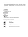
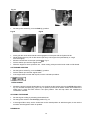
OWNER’S MANUAL
PETROL BRUSH CUTTER
261 /331
USER MANUAL, MAINTENANCE INSTRUCTIONS
AND SPARE PARTS
READ THIS MANUAL CAREFULLY BEFORE OPERATING THE MACHINE
WARNING:
THIS SYMBOL INDICATES IMPORTANT SAFETY PRECAUTIONS
DESCRIPTION
U
L HANDLE
U HANDLE
1
1
2
3
4
5
6
7
8
9
10
11
12
13
14
15
16
17
18
19
20
21
BLADE
DRIVE SHAFT
THROTTLE TRIGGER
IGNITION SWITCH
SAFETY LEVER
HANDLE
HARNESS ASSEMBLY
PETROL CAP
PURGE BULB
FUEL TANK
AIR CLEANER
CHOKE
STARTER HANDLE
DEBRIS SHIELD
CUT-OFF KNIFE
NYLON CUTTER HEAD
FRONT HANDLE
GEARBOX
REAR HANDLE
HARNESS FIXING POINT
BLADE COVER
3 Point blade for grass, weed or brush cutting applications.
Contains the drive shaft.
Spring loaded to return to idle when released.
Slide switch, forward to run, back to stop.
Prevents accidental operation of the throttle.
This handle can be adjusted for maximum comfort
Fully adjustable for maximum comfort
Push the purge bulb to remove the air from the fuel system.
Contains fuel and fuel filter.
Contains replaceable filter.
To help in cold starting.
Pull to start the engine.
Helps protect the operator from debris.
Cuts the nylon line to the correct length.
Contains replaceable nylon trimming line.
This handle can be adjusted for maximum comfort.
For attaching a blade or nylon head to.
Incorporating throttle trigger, switch, and safety lever.
Fixing point to attach the harness.
Blade cover for transportation.
1
TABLE OF CONTENTS
DESCRIPTION ........................................................................................................... 1
SAFETY SYMBOLS................................................................................................... 3
TAKING CARE OF WARNING LABELS........................................................................ 4
WARNINGS IN THE MANUAL ...................................................................................... 4
EXPLANATION OF SYMBOLS ON THE MACHINE ..................................................... 4
SAFETY PRECAUTIONS .......................................................................................... 5
INTRODUCTION ........................................................................................................... 5
WORK CLOTHING AND SAFETY EQUIPMENT .......................................................... 5
ASSEMBLY OF THE BRUSH CUTTER .................................................................... 6
INSTALLATION OF THE GUARD ................................................................................. 6
INSTALLATION OF THE NYLON HEAD....................................................................... 6
INSTALLATION OF THE 3 TOOTH BLADE.................................................................. 7
INSTALLATION OF THE U HANDLE ............................................................................ 8
FITTING OF THE L HANDLE ........................................................................................ 8
USING THE BRUSH CUTTER................................................................................... 9
CHOOSING THE CUTTING DEVICE............................................................................ 9
3-POINT BLADE ............................................................................................................ 9
SAFETY AND OPERATION ........................................................................................ 10
SAFE HANDLING OF FUEL........................................................................................ 10
BEFORE OPERATING THE BRUSH CUTTER........................................................... 10
BEFORE STARTING THE
TWO-STROKE
ENGINE ......................................................................... 10
FUEL ............................................................................................ 11
FUEL STORAGE ......................................................................................................... 12
FUELLING ................................................................................................................... 12
OPERATION ............................................................................................................ 12
STARTING THE ENGINE............................................................................................ 12
STOPPING THE ENGINE ........................................................................................... 13
MAINTENANCE ....................................................................................................... 14
TROUBLESHOOTING................................................................................................. 17
MAINTENANCE SCHEDULE ...................................................................................... 17
TECHNICAL SPECIFICATIONS.............................................................................. 18
CONDITIONS OF WARRANTY ............................................................................... 19
2
SAFETY SYMBOLS
Warning: Danger, Caution
Read the documentation and safety instructions which are
provided in this user manual.
When operating this machine, use protective equipment such as
goggles, helmet and ear defenders.
Wear security shoes and gloves.
Beware: Keep hands and feet away from moving parts. Always
keep a safe distance from the cutting parts.
Hot surface: Risk of burn.
Danger: Risk of intoxication.
Danger: Risk of fire or explosion
Directive 2000-14/CE. Guaranteed noise levels
Beware of objects being thrown from the operating zone
3
15m
50 f t
360°
Warning: Keep all people, animals and vulnerable objects at least
15 metres from the working area.
TAKING CARE OF WARNING LABELS
•
Always keep warning labels clean and free of scratches, which might make them illegible or difficult to
read. If the warning labels provided with your brush cutter become damaged, peel off, or otherwise
become illegible or difficult to read, order new labels from the authorised servicing dealer and replace
the damaged labels. When applying new labels, first wipe away any dirt and dry the surface before
applying the new label in the same place as the original label.
WARNINGS IN THE MANUAL
•
This mark indicates instructions which must be followed in order to prevent accidents which could lead
to serious bodily injury or death.
•
This mark indicates instructions which must be followed, or it leads to mechanical failure, breakdown, or
damage.
•
This mark indicates hints or useful directions in the use of the product.
EXPLANATION OF SYMBOLS ON THE MACHINE
•
For safe operation and maintenance, symbols are carved in relief on the machine:
FUEL TANK
Fuel tank 2 stroke mix
Position: Fuel cap
CHOKE OPERATION
Starting mode when the engine is hot (choke off).
Position: Air cleaner cover.
Starting mode when the engine is cold (choke on).
Position: Air cleaner cover
4
SAFETY PRECAUTIONS
INTRODUCTION
•
•
•
•
•
•
•
•
•
•
Read this Owner/Operator Manual carefully. Be sure you understand how to operate this brush cutter
properly before you use it. Failure to do so could result in serious injury.
Keep this manual handy so that you may refer to it later whenever any
questions arise. Also note that you are able to contact the dealer from
whom you purchased the product for assistance.
Always include this manual when selling, lending, or otherwise
transferring the ownership of this product.
This product has been designed to be used as a brush cutter/grass
trimmer for cutting fresh growth and it should never be used for any other
purpose, doing so could result in unforeseen accidents and injuries
occurring.
This brush cutter is equipped with extremely sharp blades, always wear sturdy
gloves when handling the blades.
When using this brush cutter for the first time, take the brush cutter to a wide,
clear, open space, start the engine, and practice handling the brush cutter until
you are sure that you will be able to handle it properly in actual operation.
You should never use this brush cutter when under the influence of alcohol,
suffering from exhaustion or lack of sleep, suffering from drowsiness as a result
of having taken medicine, or at any other time when your judgement might be
impaired or that you might not be able to operate the brush cutter properly and in
a safe manner.
Never allow children or anyone unable to fully understand the directions given in this manual to use this
brush cutter
When planning your work schedule, allow plenty of time to perform the work and allow plenty of time for
rest. Limit the amount of time you continuously use the brush cutter to 30~40 minutes per session and
take 10~20 minutes of rest between work sessions. Also, try to keep the total amount of work
performed in a single day to 2 hours.
Never run the engine indoors as the exhaust gases contain harmful carbon monoxide.
Never use the brush cutter in conditions as described below:
•
•
•
When the ground is slippery or when other conditions exist which might make it difficult to
maintain a steady posture while using the brush cutter.
At night, at times of heavy fog, or at any other times when your field of vision is limited and it would be
difficult to gain a clear view of the area where the brush cutter is to be used In heavy rain, during
lightning storms, at times of strong or gale-force winds, or at any other times when weather conditions
might make it unsafe to use this product.
Lack of sleep, tiredness, or physical exhaustion results in lower attention spans, and this in turn can
lead to accidents and injury.
WORK CLOTHING AND SAFETY EQUIPMENT
When using the product, you should wear proper clothing and protective equipment.
•
•
•
•
•
•
Helmet
Protection goggles or face protector
Ear protectors
Thick work gloves
Non-slip sole work boots
When using your brush cutter, always wear strong, durable,
work clothing; shirts should be long-sleeved and trousers
should be full-length.
5
ASSEMBLY OF THE BRUSH CUTTER
The blade fitted to the guard is sharp and can cause injury, always wear gloves
INSTALLATION OF THE GUARD
•
•
•
Lay the brush cutter on its back with the gearbox shaft facing up.
Line up the 4 screw holes in the guard with the bracket on the shaft Fig 1.
Insert 4 screws through the guard into the captive nuts in the bracket (Fig2) and tighten
Fig 2
Fig 1
The blade fitted to the guard is sharp and can cause injury, always wear gloves
INSTALLATION OF THE NYLON HEAD
•
•
•
•
•
•
Lay the brush cutter on its back with the gearbox shaft facing up.
Rotate the gear box shaft until the hole in the holder A lines up with the slot in the plastic guard Fig 3.
Insert the Allen key into the hole in the gearbox cover and into holder A Fig 4.
Screw the nylon head anti-clockwise (turn left) Fig 5 onto the threaded shaft on the end of the gearbox.
Make sure that the nylon head is securely locked in position.
Remove the Allen key.
Fig 3, PLASTIC GUARD
HOLDER A
Fig 4,
ALLEN KEY
6
Fig 5, SCREW THE HEAD ANTI-CLOCKWISE
INSTALLATION OF THE 3 TOOTH BLADE
Always wear gloves when touching the blade
•
•
•
•
Lay the brush cutter on its back with the gearbox shaft facing up.
Rotate the gearbox shaft until the hole in the holder A lines up with the slot in the plastic guard Fig 3.
Insert the Allen key into the hole in the gearbox cover and into holder A Fig 4.
Place the 3 tooth blade on the holder A, centring the blade on the raised centre Fig 6 and Fig 7.
Fig 6,
HOLDER A
•
•
•
•
•
Fig 7,
Fig 8,
RAISED CENTRE
HOLDER B
.
Fit the holder B (Fig 8) and then the washer.
Screw the nut anti-clockwise (turn left) and tighten using the spanner provided (Fig 9).
Make sure that the blade is completely and safely locked in position, and there is no space between the
blade and the blade holder.
Fit split pin (fig 10).
Remove the Allen key.
Fig 9
Fig 10
THE BLADE MUST BE CORRECTLY POSITIONED ON THE UPPER BLADE CLAMP OTHERWISE
SERIOUS DAMAGE AND INJURY TO PERSONS AND PROPERTY COULD RESULT.
7
INSTALLATION OF THE U HANDLE
•
•
Remove the upper cap from the bracket by undoing the 4 screws.
Install the handle assembly into the seating support Fig 11, upper cap and secure using the 4 screws
Fig 12 making sure that the controls are located on the right and adjust the handle for maximum comfort
before securing.
Fig 11
Fig 12
FITTING OF THE L HANDLE
Fix the loop-handle to the shaft over the rubber block provided 1, Fig 13. Adjust to a comfortable working
position then tighten the fixing screws securely Fig 14.
Fig 13,
Fig 14,
8
USING THE BRUSH CUTTER
CHOOSING THE CUTTING DEVICE
Choose the most suitable cutting device for the job to be done, according to these general
indications:
• The cutting line head can eliminate tall grass and non-woody vegetation
• The 3-point blade is suitable for cutting brushwood and small shrubs up to 2 cm in diameter.
CUTTING LINE HEAD
•
•
•
•
•
Cut the grass in 1.5 metre widths, keeping the machine well balanced.
Avoid engaging stones, piles of earth, small pieces of wood or anything that could be hidden or difficult
to see in the grass. If a large object is accidentally struck, if the cutting head gets blocked, overloaded
or stringy material gets wrapped in the cutting head: reduce the engine speed so the engine idles.
Make sure that the cutting head has stopped rotating switch off the engine and remove the material.
Put the grass trimmer on the ground and check that the cutting head has not been damaged. If
necessary, change the cutting head. If the head is only wrapped by vegetation, remove by hand and
clean the cutting head.
Always wear safety gloves for this operation and ensure the engine is switched off and the head is
stationary.
When the 2 nylon cords become too short, accelerate the engine and bump the nylon head on the
ground. Automatically the 2 nylon cords will feed out and be cut to the correct length. Repeat the
operation if necessary.
3-POINT BLADE
•
•
Start cutting above the undergrowth and then move down with the blade so as to cut the brush into
small pieces.
Avoid hitting stones, piles of earth, small pieces of wood or anything that could be hidden or difficult to
see in the grass.
9
SAFETY AND OPERATION
•
•
•
•
•
•
This brush cutter is equipped with a very sharp blade, and when used incorrectly the blades can be
extremely dangerous.
Improper handling can cause accidents which may in turn lead to serious injury or death. For this
reason, you should always be careful to adhere to the following instructions when using your brush
cutter
Never hold the brush cutter in a way in which the cutting head is pointing towards someone else.
Never allow the blades to come into contact with your body.
Always turn off the engine before adjusting the brush cutter, or at any time when coming into close
proximity with the cutting head.
Always wear thick work gloves when adjusting the brush cutter.
SAFE HANDLING OF FUEL
•
•
•
•
•
•
The engine of the brush cutter is designed to run on a two stroke oil/fuel mixture.
This fuel is highly flammable, never store cans of fuel or refill the fuel tank in any
place where there is a source of heat or fire, which might ignite the fuel.
Do not smoke whilst operating the brush cutter or refilling, keep lit cigarettes away
from the brush cutter at all times.
When refilling the fuel tank always stop the engine first and carefully make sure that
there are no sparks or naked flames anywhere nearby before refuelling.
If any fuel spillage occurs during refuelling, use a dry rag to wipe any fuel which has been spilled onto
the brush cutter before starting the engine.
After refuelling, screw the fuel cap back tightly onto the fuel tank and carry the brush cutter to a spot 5
metres or more away from where it was refuelled before starting the engine.
BEFORE OPERATING THE BRUSH CUTTER
•
•
•
•
Before beginning work, carefully check the work area and remove any obstacles. within a perimeter of
15 metres of the work area should be considered a hazardous area into which no-one should enter
while the brush cutter is being used, and when necessary this area should be marked with a warning
rope, warning signs, or other forms of warning.
When work is to be performed simultaneously by two or more operators, care should also be taken to
constantly look around to check the presence and locations of other operators within the work area to
maintain a safe distance between each operator.
Before beginning work, each component of the brush cutter should be checked to make sure that it is in
proper working order, make sure that there are no loose screws or bolts, fuel leaks, ruptures, dents,
broken guards or any other problems which might interfere with safe operation.
Keep all parts of your body away from the cutting head when the engine is running.
BEFORE STARTING THE ENGINE
•
•
•
Carefully check the work area to make sure that no obstacles exist within a perimeter of 15metres
around the brush cutter before starting the engine.
To start the engine, place the brush cutter onto the ground in a flat clear area and hold it firmly in place
to ensure that neither the cutting head nor the throttle come into contact with any obstacles when the
engine starts.
After starting the engine, make sure that the cutting head stops moving when the throttle trigger is
released (idle). If the cutting head continues to move when the engine is at idle, adjust the idle screw on
the carburettor to a point where the cutting head stops moving, if this cannot be achieved, take the
brush cutter to your authorised service dealer for adjustment.
10
AVOID NOISE PROBLEMS
•
•
•
Check and follow the local regulations for sound levels and hours of operation for garden machinery.
In general, operate brush cutters between 8 am and 5 pm on week days and 9 am to 5 pm at weekends.
Avoid using the brush cutter late at night and/or early in the morning.
SAFETY WHEN USING THE BRUSH CUTTER
•
•
•
•
•
•
•
•
•
•
•
When using the brush cutter, grip the handles firmly with both hands, place your feet slightly apart so
your weight is distributed evenly across both legs, and always maintain a steady even posture while
working.
Maintain full engine speed when cutting.
Never allow other persons to come within the work area as doing so might expose them to danger.
Keep work area clear of all persons, particularly small children and pets. Injury may
result from flying debris.
If grass or other objects get caught in the brush cutter during operation, always stop the
engine before removing the object.
Never touch the spark plug or plug HT cable while the engine is in operation, doing so
may result in an electrical shock.
Never touch the exhaust, spark plug, or any metallic parts while the engine is in
operation or immediately after shutting down the engine. these parts reach high
temperatures during operation and doing so could result in serious burns.
When you finish cutting in one location and wish to continue work in another area, stop
the engine.
Always remove fuel from the fuel tank before transportation to prevent fuel spillage.
Never leave the brush cutter exposed to direct sunlight as this can heat the fuel tank and
may cause a discharge of fuel, and flood the engine.
Be careful not to hit the nylon cutting head against stones or the ground.
TWO-STROKE
•
•
•
•
FUEL
Fuel is very flammable. Do not smoke or bring any flame or sparks near fuel.
Always stop the engine and allow it to cool before refuelling.
Refuel outdoors on bare ground, restart engine at least 5m away from the refuelling stop.
The engine is lubricated by oil mixed into petrol. Prepare a mixture of unleaded petrol and
semi-synthetic two-stroke oil that meets the specifications of: API TC, ISO-L-EGC, JASO FC
(Low Smoke) oil.
Recommended mixing ratio is 40:1
•
•
•
•
FUEL WITH NO OIL (RAW PETROL) will cause severe damage to the engine which is not
covered by manufacturer's warranty.
Use fresh, unleaded petrol (95 RON) and semi-synthetic oil specially made for high performance
two-stroke engines. Mix in a ratio of 40 parts petrol to 1 part of oil.
By using two-stroke oil specially made for two-stroke engines you will reduce the formation of ash and
carbon deposits on the spark plug, piston, exhaust muffler and cylinder as well as reducing emissions of
harmful exhaust gases.
Oil FOR 4-CYCLE ENGINES should not be used as two-stroke lubrication oil as it can cause fouling of
the spark plug, exhaust port blocking, piston ring sticking and other internal engine damage.
11
FUEL STORAGE
•
•
•
•
Mixed two-stroke fuel which has been left unused for a period of one month or more may damage
the carburettor and result in the engine failing to start or operate correctly.
When storing the brush cutter for a period of more than one month, empty the fuel tank, and
run the engine to empty the carburettor of fuel.
Two-stroke fuel can cause deterioration of rubber and/or plastic components during prolonged
storage.
It is important to only use good quality, fresh fuel mix.
FUELLING
•
•
•
•
•
•
Shake the fuel container to thoroughly mix the two-stroke oil and petrol.
Clean dirt from around the fuel cap before removing.
Pour two-stroke fuel into the fuel tank with a filtered funnel, up to 80% of the fuel tanks capacity.
Replace the fuel cap and tighten securely. Spilled fuel must be wiped away from the brush cutter before
starting the engine.
Move at least 5m away from the refuelling area before restarting the engine.
When refilling the tank, always turn off the engine and allow it to cool down. Take a
careful look around to make sure that there are no sparks or naked flames anywhere
nearby before refuelling.
OPERATION
Keep clear of the cutting head as it may start moving when the engine starts.
STARTING THE ENGINE
•
CAUTION do not pull the starter cord all the way out and do not let go of the starter handle when the
cord is extended, this can damage the starter mechanism.
COLD ENGINE STARTING
•
•
Rest the unit on a flat, firm surface. Keep the cutting head off the ground and clear of surrounding
objects as it may start moving when starting the engine.
Push the air purge bulb a Fig 15 until fuel is visible in the clear return fuel line b.
Fig 15 (a) air purge bulb, (b) clear tube
•
Move the choke lever to the closed
position Fig 16.
12
Fig 17
Fig 16
•
Set the ignition switch Fig 18 to the RUN ( I ) position.
Fig 18
•
•
•
•
•
Fig 18
Slowly pull the recoil starter handle until engagement of the paw with the flywheel is felt.
While holding the unit, pull out the starter rope firmly until engine fires (indicated by a ‘cough’
from the engine).
Move the choke lever to the open position
Fig 17.
Pull the starter rope until the engine starts.
Allow the engine to warm up before use. When cutting, always use the brush cutter on full throttle.
HOT ENGINE STARTING
•
•
•
Set the ignition switch Fig 18 to the RUN ( I ) position.
Pull the starter rope until the engine starts.
If the engine does not start after 5 pulls, use the cold start procedure.
OVERCHOKING
•
Should the engine become flooded due to over-choking set the ignition switch to the STOP (O) position
Fig 18, unscrew the spark plug, wipe it dry or replace, pull the recoil starter several times without the
spark plug in place and with choke in the open position. This will help clean and ventilate the
combustion chamber.
STOPPING THE ENGINE
•
Set the engine to idling by releasing the throttle lever.
•
Set the ignition switch to the STOP (O) position Fig 18.
•
If the engine fails to stop, set the choke lever to the closed position to stall the engine; do not use the
machine until the ignition switch is repaired.
RUNNING IN
13
•
During the first ten hours of work, avoid running the engine at maximum speed for a prolonged
period until all the components have bedded in, after the engine has been run-in, it will reach its
maximum power.
MAINTENANCE
IMPORTANT
• After every use, check that all nuts, bolts and screws are securely fastened and tighten if
necessary.
FUEL FILTER
•
Every 15 hours of operation, using a wire hook, take the fuel filter from the fuel tank Fig19 and clean or
replace with a new fuel filter.
Fig 19
Fig 20
fuel filter
SPARK PLUG
•
Poor starting or misfiring is often caused by a fouled or defective spark plug, clean and reset the
gap to 0.65 mm, or replace the spark plug with NGK: BPRM7A as necessary Fig 20.
AIR FILTER
•
•
Before using the brush cutter, check the air filter Fig 22. Being clogged, will reduce the engine
performance.
Remove the air filter cover by undoing the cover screw Fig 21, clean the filter element in warm, soapy
water, dry completely before installing. If the element is broken or shrunk, replace with a new one.
FIG 21 AIR FILTER COVER SCREW
Fig 22 AIR FILTER
14
CARBURETTOR
•
•
The carburettor mixture setting has been set at the factory and will not need adjusting.
Adjusting the idle speed Fig 23. If adjustment is necessary turn the T screw clock wise until the blades
start to move, then turn the screw T anticlockwise until the blades stop.
,
Fig 23
•
T screw
If the idle speed cannot be adjusted to stop the cutting head moving at idle, contact your dealer
for repair before use.
Fig 24
Fig 24
SAFETY LOCK,
SAFETY LOCK
THROTTLE LEVER
THROTTLE LEVER
SAFETY LOCK
•
•
•
•
The safety lock is to prevent the throttle lever from accidentally being engaged.
The throttle lever, Fig 24, can only be pressed in if the safety lock is held down.
Check if the safety lock and throttle lever returns to its original position and the engine returns to idling
when you release your hand from the handle.
Any defects contact your nearest service agent for repairs before using the machine.
STORAGE
•
•
Remove the spark plug, pour a small amount of oil into the cylinder. Rotate the crankshaft several
times using the starting rope in order to distribute the oil. Put the spark plug back in.
Remove the fuel from the machine.
15
GEAR CASE
•
Remove the bolt A on the gear case Fig 25, top up the gearbox using Lithium grease and refit the bolt.
Fig 25
Bolt A
REPLACING THE NYLON CORD
Check to see if the nylon head is damaged before replacing the cord. If you can see serious traces of wear
or damage, you must replace the complete nylon head.
1. Stop the engine
2. Open the nylon head by pushing on the catch, Fig 26, and twisting the cover anti-clock wise.
3. Pull the bobbin out of the nylon head and take out the rest of the nylon cords.
4. Cut the cords, 2.4mm Ø and 5 meters long into two equal lengths.
5. Make a loop folded at one end of each of the two nylon cords and insert these into the two holes
provided on the bobbin, Fig 27. Wind the lines clockwise maintaining an even and firm tension onto the
bobbin, being careful not to twist the line.
6. After winding the cord, insert both ends into the notches on the bobbin, Fig28.
7. Introduce each end of the cords into the holes provided Fig 29. The cords should stick out appx 15 cm
either side,
8. Pull the cords to free them from the notches and refit the spool cover.
Never use a cutting device other than those supplied by the manufacturer. (Steel cord is never
allowed) Always use original spare parts in order to benefit from continuous warranty
Fig 26
Fig 27
catch
Fig 28
Fig 29
16
TROUBLESHOOTING
Engine will not start, power loss.
•
•
•
•
•
•
Check that the fuel tank is not empty. Fill with mixed fuel.
The fuel does not reach the carburettor. Change the fuel filter in the fuel tank.
There is water in the fuel. Drain and clean the fuel system.
The air filter is dirty. Clean or replace the air filter.
There are carbon deposits in the exhaust muffler restricting the engine. Clean or change the
muffler.
Spark plug is worn. Replace spark plug.
MAINTENANCE SCHEDULE
Component
Procedure
Before
use
Fuel leaks / spillage
Wipe up
Fuel tank, filter
Inspect / clean
Idle adjust screw
See above
Spark plug BPMR7A
Clean and readjust
plug gap
Cylinder fins, Intake air
cooling vent
Clean
Muffler, Spark arrestor,
cylinder exhaust port
Clean
Throttle lever, ignition
switch
Check operation
X
Air filter
Clean
X
Screws, nuts, bolts
Tighten / replace
X
Check
X
Every 15
Hours
Every 50
Hours
Note
X
Replace if necessary
X
Adjust carburettor if
necessary
X
GAP .025” (0.6-0.7mm)
Replace, if necessary
X
X
X
Not adjustment
screws
Check all nuts & bolts
Grease the gear box
Every 25
Hours
17
TECHNICAL SPECIFICATIONS
MODEL
Engine
MITOX 261
Type
Model
Displacement : ( cm3)
Max. output
Idle speed: rpm (min –1)
Air cooled 2-stroke petrol engine
IE34F-2E
25.4 cc
0.7 (kw) in accordance with ISO 8893
Max. power speed: rpm (min –1)
Fuel tank capacity
2800±150
9800
0.65L
Fuel
Carburetor
Spark Plug
Mixture (Petrol 40 : Oil 1)
Diaphragm type
NGK-R BPMR7A
Transmission
Fixation hole diameter: (mm)
Dry Weight w/o harness & gasoline
Overall size (LxWxH)
Reduction ratio
Cutting head
Cutting width 3 teeth blade
MODEL
Engine
Centrifugal clutch, spur gear, cam-crank
26
6.2 kg
1800mmx380mmx250mm
22 :17
255mm
Nylon head
3 teeth blade thickness
Cutting line diameter
415mm
1.4mm
2.5mm
Max. blade rotation speed:
7500 rpm (min –1)
Rotation direction
Counter Clockwise(as seen from above)
MITOX 331
Type
Model
Displacement : ( cm3)
Max. output
Idle speed: rpm (min –1)
Air cooled 2-stroke petrol engine
IE36F-E
32.6 cc
0.9 (kw) in accordance with ISO 8893
–1
Max. power speed: rpm (min )
Fuel tank capacity
2800±150
10200
1L
Fuel
Carburetor
Spark Plug
Transmission
Mixture (Petrol 40 : Oil 1)
Diaphragm type
NGK-R BPMR7A
Centrifugal clutch, spur gear, cam-crank
Fixation hole diameter: (mm)
Dry Weight w/o harness & gasoline
Overall size (LxWxH)
Reduction ratio
Cutting head
Cutting width 3 teeth blade
Nylon head
3 teeth blade thickness
Cutting line diameter
26
7.5kg
1800mmx630mmx390mm
22 :17
255mm
415mm
2.8mm
2.5mm
Max. blade rotation speed:
7800 rpm (min –1)
Rotation direction
Counter Clockwise(as seen from above)
Above specifications are subject to change without notice.
18
CONDITIONS OF WARRANTY
The manufacturer warrants the product against faulty materials and workmanship for a period of 2 years
from the date of first purchase. The warranty is applicable when the product is used in a “home owner”
application. If products are used for commercial or professional purposes, the warranty period is for 3
months from the date of first purchase. Warranty does not extend to failure due to fair wear and tear.
The manufacturer undertakes to replace, any spare parts that are classified as defective by an appointed
Mitox service dealer. The manufacturer will not accept liability for the replacement of the machine, either
partially or wholly, and /or consequential damages and /or interest charge either directly or indirectly.
Warranty does not cover failure due to:
• Insufficient maintenance.
• Incorrect fuel mixture and stale fuel.
• Abnormal use or accidental damage.
• Incorrect assembly, adjustment or operation of the product.
• Spare parts that are subject to wear e.g. safety parts, blades, blade supports, bearings, cables,
guards, deflectors, spark plugs, air filters etc.
Neither does warranty extend to:
• Freight and packing costs.
• Use of non-genuine spare parts i.e. those from another manufacturer.
• Use of the machine for any other purpose than that for which it was designed.
• Use and maintenance of the machine in a manner not described in the owner’s manual.
As part of our policy of continuous product improvement, we reserve the right to alter or amend
this specification without notice. As a result, the product may differ from the information contained
herein, but any alteration will only be implemented without notice if it is classified as an
improvement to the above specification.
READ THE MANUAL CAREFULLY BEFORE OPERATING THE MACHINE
When ordering spare parts, please quote the part number, this can be found in the parts list included in this
manual.
Retain the receipt of purchase without which no warranty can be offered.
To find your nearest stockist and authorised service dealer:
www.mitoxgm.co.uk
U.K. IMPORTER
Mitox Garden Machinery
Wincanton Business Park
WINCANTON
Somerset
BA9 9RS
U.K.
19
CE declaration of Conformity Declaration de Conformité CE Dichiarazione di Conformita CE Declaraciòn de Conformidad CE The undersigned- Je soussigné - Il sottoscritto -EL abajo firmante : Mr KEJUN LIU PRESIDENT of :
Shanghai Huasheng International Business Co., Ltd
Room 1502A, 118 Xinling Road, Pudong, Shanghai CHINA
declares under its own responsability, that the following brushcutters with internal combustion engine
déclare sous sa propre responsabilité que les débroussailleuses, équipées d'un moteur thermique
dichiara sotto la sua propria responsabilità che i seguenti decespugliatori con motore termico a scoppio
declara bajo su propria responsabilidad que las desbrozadoras con motor de combustion
MITOX
Brand. Marque. Marca
Type. N° serial + engine
Type. N° de série + moteur
Tipo. N° di seria + motore
Tipo. N° de seria + motor
261, 331 or CG260-E, CG330-E N°…….Engine ref: 1E34F-2E, 1E36F-E
are in accordance with :
sont conformes à :
Sono in conformità con :
son conformes con :
Directives 2006/42/EC, 2004/108/ EEC, 2000/14/EC , 2005/88/EC
For the checking of the conformity to the above Directives the following Standards have been used :
Pour la vérification de la conformité aux Directives ci-dessus, les Normes suivantes ont été utilisées:
Per il controllo della conformita alle sopraindicate Direttive sono state seguite le seguente Normative :
Para comprobar la conformidad de las Directivas anteriores se han utilisado las siguientes Normas :
EN ISO 11806 - EN 14982
Mesured Sound power level LWA, M :
Niveau de puissance accoustique mesuré LWA, M :
Livello di potenza accustica misurato LWA, M :
Nivel de potencia acùstica mesurado LWA, M :
261, 331 or CG260-E, CG330-E : 111 dB(A)
Guarantided Sound power level LWA, G :
Niveau de puissance accoustique garanti LWA, G :
Livello di potenza accustica garantito LWA, G :
Nivel de potencia acùstica garantito LWA, G :
261, 331 or CG260-E, CG330-E : 113 dB(A)
Done at:
Fait à :
Fatto a :
Shanghai City
25 Sep. 2010
Name :
Nom :
Nome :
Mr KEJUN LIU
PRESIDENT