1
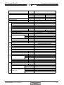
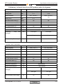
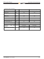
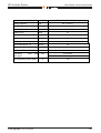
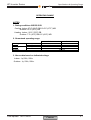
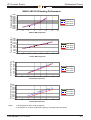
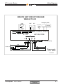
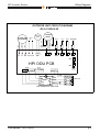
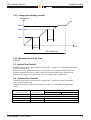
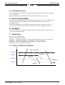
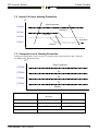
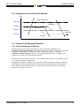
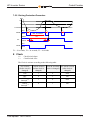
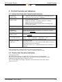
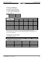
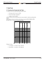
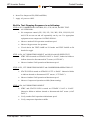
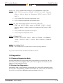
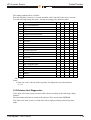
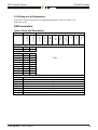
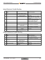
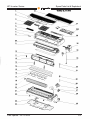
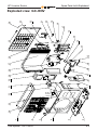
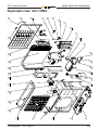
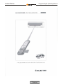
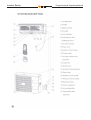
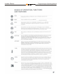
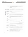
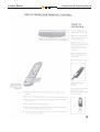
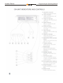
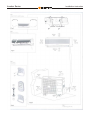
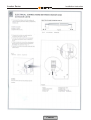
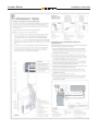
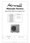
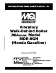
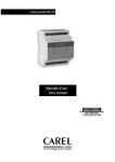
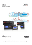
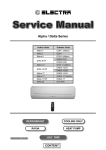
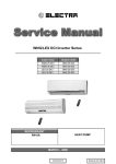
ELECTRA CONSUMER PRODUCTS LTD
Version 1.0
Date: 01/11/2002
HPI Inverter Series
Contens
TECHNICAL AND SERVICE MANUAL
CONTENTS
1.
FEATURES ............................................................................ 1
2.
SPECIFICATIONS & OPERATING RANGE .......................... 2
3.
PERFORMANCE CURVES ................................................... 3
4.
OUTLINE DIMENSIONS ....................................................... 4
5.
REFRIGERATION DIAGRAMS ............................................. 5
6.
WIRING DIAGRAMS ............................................................. 6
7.
CONTROL FUNCTION ......................................................... 7
8.
TROUBLESHOOTING ........................................................... 8
9.
INDOOR & OUTDOOR PARTS LIST .................................... 9
10. OPERATING & INSTALLATION MANUAL ............................ 10
HPI Inverter Series
Features
HPI Series Features
x
x
x
x
x
x
x
x
x
x
x
x
x
Single split AC Inverter
R-22 and R407c models
Lego concept (R407c only)
Wide dynamic range
Energy saving
Very low noise levels
Variable speed indoor and outdoor fan motors
Base heater
Self contained diagnostics
Full Electro Magnetic Compliance
CE, CB Compliance
Power Factor Correction
Supports IAQ feature – Ioniser, Electro Static filter, and Fresh
Air
Available R-22 Models:
2.5
Outdoor Unit Models
GC-9INV
GC-11INV
Indoor Unit Models
WNG
Nominal Cooling Capacity [kW]
3.2
6
Ɣ
Ɣ
Ɣ
Ɣ
2.5
Nominal Cooling Capacity [kW]
3.2
Available R-407c Models:
Outdoor Unit Models
ONG3-9INV
ONG3-11INV
GC-18INV
Indoor Unit Models
WNG
ECF (K)
PXD
WMN
Last update: 02/11/2002
6
Ɣ
Ɣ
Ɣ
Ɣ
Ɣ
Ɣ
Ɣ
Ɣ
Ɣ
Contens
Ɣ
Ɣ
Ɣ
1.1
HPI Inverter Series
Specifications & Operating Range
Item
Function
Capacity
Total Input
Running Current
Power Supply (ph, Hz, voltage)
External finish
I Heat exchanger
N Fan (drive)
D Fan motor output
O Airflow (Hi)
O Operation control type
R Noise level(Hi)
Condensate drain I.D.
U Dimensions
N
I
T Weight
Packing dimensions
Unit stacking
O Refrigerant control
U Compressor type
T Model
D Starter type
O Protection device
O Heat exchanger
R Fan (drive) x No.
Motor output
Defrost method
U Noise level
N Dimensions
I
T
Weight
Packing dimensions
Unit stacking
Refrigerant
T Charge
U Tube size
B O.D.
I Connection method
N between the indoor and
G outdoor unit
Last update: 02/11/2002
WNG-9INV/GC-9INV
Model
Kal/hr
Btu/hr
W
W
A
W
m/hr
W
D
H
db(A)
mm(in)
mm(in)
mm(in)
mm(in)
Kg(Ibs)
mm
units
W
W
D
H
db(A)
mm
mm
mm
Kg.(Ibs)
mm.
units
gr.(Ibs)
liquid mm.(in.)
suction mm.(in.)
indoor & outdoor
height difference
tubing length
Heating
Cooling
2150(820-2750)
2580(850-3265)
8540(3410-10920)
10240(3410-13000)
2500(1000-3200)
3000(1000-3800)
870(400-1450)
1100(375-1800)
4.4
4.4
single᧨50HZ᧨220V
Texture
Louver/hydrophilic fin coil
Crossflow
20
400
420
Remote control/ LED
37
39
16
810
190
285
10
990 x 340 x 240
8
Capilary tube
Rotary/single piston/ inverter
KHV104FCTC
Line start
Temp/Current
Louver/hydrophilic fin coil
Propeller (direct) x 1
30
Reverse cycle
54
830
240
545
34
880 x 310 x 610
3
R᧩22
850(7.5m)
6.35 (1/4)
9.52 (3/8)
Flared
Max. 6m
Max.12m
Contens
2.1
HPI Inverter Series
Item
Function
Capacity
Total Input
Running Current
Power Supply (ph, Hz, voltage)
Ionizer
Electrostatic Filter
External finish
I Heat exchanger
N Fan (drive)
D Fan motor output
O Airflow (Hi)
O Operation control type
R Noise level(Lo-M-Hi)
Condensate drain I.D.
U Dimensions
N
I
T Weight
Packing dimensions
Unit stacking
O Refrigerant control
U Compressor type
T Model
D Starter type
O Protection device
O Heat exchanger
R Fan (drive) x No.
Motor output
Defrost method
U Noise level
N Dimensions
I
T
Weight
Packing dimensions
Unit stacking
Refrigerant
T Charge
U Tube size
B O.D.
I Connection method
N between the indoor and
G outdoor unit
Last update: 02/11/2002
Specifications & Operating Range
WNG-11INV/GC-11INV
Model
Heating
Cooling
2750(775-3270)
3610(775-4300)
10910(3070-12960)
14322(3070-17050)
3200(900-3800)
4200(900-5000)
1200(400-1700)
1650(400-2250)
5.5
7
single᧨50HZ᧨230V
YES (optional)
YES (optional)
Texture
Louver/hydrophilic fin coil
Crossflow
W
20
m/hr
482
570
Remote control/ LED
30.7-35.5-39
31.8-36-40.5
db(A)
mm(in)
16
W
mm(in)
810
D
mm(in)
190
H
mm(in)
285
Kg(Ibs)
10.5
mm
990 x 340 x 240
units
8
Capilary tube
Rotary/single piston/ inverter
SHV130FGEC
Line start
Temp/Current
Louver/hydrophilic fin coil
Propeller (direct) x 1
32
W
Reverse cycle
db(A)
57
W
mm
830
D
mm
240
H
mm
545
34
Kg.(Ibs)
880 x 310 x 610
mm.
units
3
R᧩22
(6m)990
gr.(Ibs)
liquid mm.(in.)
6.35 (1/4)
12.7 (1/2)
suction mm.(in.)
indoor & outdoor
Flared
height difference
Max. 6m
Max.12m
tubing length
Additional Charge 6 m<Lin<8m:+5g/m Lin>8m:+9g/m
Kal/hr
Btu/hr
W
W
A
Contens
2.2
HPI Inverter Series
Specifications & Operating Range
Preliminary technical data of new HPI product under development
:1*21*,195&
:1*21*,195&
᧤᧥
᧤᧥
&RROLQJ&DSDFLW\
N:
&RROLQJ&23
::
+HDWLQJ&DSDFLW\
.:
᧤᧥
᧤᧥
+HDWLQJ&23
::
0D[,QGRRU1RLVH/HYHO
G%$
0LQ,QGRRU1RLVH/HYHO
G%$
0D[2XWGRRU1RLVH
G%$
0LQ2XWGRRU1RLVH
G%$
,QGRRU8QLW'LPHQVLRQV
PP
2XWGRRUXQLWGLPHQVLRQV
PP
&RQQHFWLQJ
7XEH
6L]H
[[
[[
PP
OLTXLG
OLTXLG
IODUHW\SH
JDV
JDV
0D[&RQQHFWLQJ7XEH/HQJWK
P
2. K/ONG3 -9INV, 11INV R407C
.21*,195&
.21*,195&
᧤᧥
᧤᧥
&RROLQJ&DSDFLW\
N:
&RROLQJ&23
::
+HDWLQJ&DSDFLW\
.:
᧤᧥
᧤᧥
+HDWLQJ&23
::
0D[,QGRRU1RLVH/HYHO
G%$
0LQ,QGRRU1RLVH/HYHO
G%$
0D[2XWGRRU1RLVH
G%$
0LQ2XWGRRU1RLVH
G%$
,QGRRU8QLW'LPHQVLRQV
PP
2XWGRRUXQLWGLPHQVLRQV
PP
&RQQHFWLQJ
7XEH
6L]H
[[
[[
PP
OLTXLG
IODUHW\SH
OLTXLG
JDV
0D[&RQQHFWLQJ7XEH/HQJWK
P
Last update: 02/11/2002
JDV
Contens
2.3
HPI Inverter Series
Specifications & Operating Range
3.PXD/ONG3 9INV,11INV R407C
3;'21*,195&
3;'21*,195&
᧤᧥
᧤᧥
&RROLQJ&DSDFLW\
N:
&RROLQJ&23
::
+HDWLQJ&DSDFLW\
.:
᧤᧥
᧤᧥
+HDWLQJ&23
::
0D[,QGRRU1RLVH/HYHO
G%$
0LQ,QGRRU1RLVH/HYHO
G%$
0D[2XWGRRU1RLVH
G%$
0LQ2XWGRRU1RLVH
G%$
,QGRRU8QLW'LPHQVLRQV
PP
2XWGRRUXQLWGLPHQVLRQV
PP
&RQQHFWLQJ
7XEH
6L]H
[[
[[
PP
IODUHW\SH
0D[&RQQHFWLQJ7XEH/HQJWK
P
Last update: 02/11/2002
OLTXLG
OLTXLG
JDV
JDV
2.4
HPI Inverter Series
Specifications & Operating Range
4. PXD18/K18/WMN18-GC18RC INV R407C
:01*&,195&
&RROLQJ&DSDFLW\
N:
&RROLQJ&23
::
+HDWLQJ&DSDFLW\
N:
+HDWLQJ&23
::
0D[,QGRRU1RLVH/HYHO
G%$
0LQ,QGRRU1RLVH/HYHO
G%$
0D[2XWGRRU1RLVH
G%$
0LQ2XWGRRU1RLVH
G%$
2XWGRRUXQLWGLPHQVLRQ
PP
,QGRRUXQLWGLPHQVLRQ
&RQQHFWLQJ
7XEH
PP
6L]H
PP
IODUHW\SH
[[
[[
OLTXLG
JDV
0D[&RQQHFWLQJ7XEH/HQJWK
P
.*&5&,195&
&RROLQJ&DSDFLW\
N:
&RROLQJ&23
::
+HDWLQJ&DSDFLW\
.:
+HDWLQJ&23
::
0D[,QGRRU1RLVH/HYHO
G%$
0LQ,QGRRU1RLVH/HYHO
G%$
0D[2XWGRRU1RLVH
G%$
0LQ2XWGRRU1RLVH
G%$
2XWGRRUXQLW'LPHQVLRQV
,QGRRU8QLW'LPHQVLRQV
&RQQHFWLQJ
7XEH
6L]H
᧤᧥
[[
PP
PP
OLTXLG
IODUHW\SH
0D[&RQQHFWLQJ7XEH/HQJWK
Last update: 02/11/2002
JDV
P
2.5
HPI Inverter Series
Specifications & Operating Range
3;'*&5&,195&
&RROLQJ&DSDFLW\
N:
᧤᧥
&RROLQJ&23
::
+HDWLQJ&DSDFLW\
.:
᧤᧥
+HDWLQJ&23
::
0D[,QGRRU1RLVH/HYHO
G%$
0LQ,QGRRU1RLVH/HYHO
G%$
0D[2XWGRRU1RLVH
G%$
0LQ2XWGRRU1RLVH
G%$
2XWGRRUXQLW'LPHQVLRQV
PP
[[
,QGRRU8QLW'LPHQVLRQV
PP
[[
PP
OLTXLG
&RQQHFWLQJ
7XEH
6L]H
IODUHW\SH
0D[&RQQHFWLQJ7XEH/HQJWK
Last update: 02/11/2002
JDV
P
2.6
HPI Inverter Series
Specifications & Operating Range
OPERATING RANGE
NOTES:
1. Rating conditions ISO DIS 5151
Cooling: Indoor: 27qC (80qF) DB 19.5qC (67qF) WB
Outdoor: 35qC (95qF) DB
Heating: Indoor : 20qC (70qF) DB
Outdoor: 7qC (45qF) DB 6qC (43qF) WB
2. Guaranteed operating range:
Cooling
Heating
Indoor
Upper limit
Lower limit
Upper limit
Lower limit
Voltage
32qC DB, 23qC WB
21qC DB, 15qC WB
27qCD
20qC DB
Outdoor
46qC DB
10qC DB
21qC DB, 15.5qC WB
-14qC DB, -15qC WB
198 - 254v
3. Above data based on indicated voltage
.
Indoor : 1ij,230v, 50Hz
Outdoor: 1ij, 230v, 50Hz.
Last update: 02/11/2002
Contens
2.7
HPI Inverter Series
Performance Curves
Cooling Capacity [W]
WNG-9 INV R-22 Cooling Performance
3500
3400
3300
3200
3100
3000
2900
2800
2700
2600
2500
2400
2300
2200
2100
2000
Indoor WB 19
Indooe WB 21
Indoor WB 23
10
15
20
25
30
35
40
45
Power Consumption [W]
Outdoor DB Temperature
1500
1400
1300
1200
1100
1000
900
800
700
600
500
Indoor WB 19
Indooe WB 21
Indoor WB 23
10
15
20
25
30
35
40
45
Suction Pressure [psi g.]
Outdoor DB Temperature
100
90
Indoor WB 19
80
Indooe WB 21
70
Indoor WB 23
60
50
10
15
20
25
30
35
40
45
Discharge Pressure [psi g.]
Outdoor DB Temperature
350
325
300
275
250
225
200
175
150
Indoor WB 19
Indooe WB 21
Indoor WB 23
10
15
20
25
30
35
40
45
Outdoor DB Temperature
Notes:
1. All temperatures are in Celsius Degrees.
2. All data are for nominal compressor frequency, and high indoor fan speed.
Last update: 02/11/2002
Contens
3.1
HPI Inverter Series
Performance Curves
Heating Capacity [W]
WNG-9 INV R-22 Heating Performance
4500
4250
4000
3750
3500
3250
3000
2750
2500
2250
2000
1750
1500
Indoor DB 15
Indoor DB 20
Indoor DB 25
-15
-10
-5
0
5
10
15
20
Power Consumption [W]
Outdoor WB Temperature
1500
1400
1300
1200
1100
1000
900
800
700
600
500
Indoor DB 15
Indoor DB 20
Indoor DB 25
-15
-10
-5
0
5
10
15
20
Suction Pressure [psi g.]
Outdoor WB Temperature
100
90
80
70
60
50
40
30
20
10
0
Indoor DB 15
Indoor DB 20
Indoor DB 25
-15
-10
-5
0
5
10
15
20
Discharge Pressure [psi g.]
Outdoor WB Temperature
450
425
400
375
350
325
300
275
250
225
200
Indoor DB 15
Indoor DB 20
Indoor DB 25
-15
-10
-5
0
5
10
15
20
Outdoor WB Temperature
Notes:
1. All temperatures are in Celsius Degrees.
2. All data are for nominal compressor frequency, and high indoor fan speed.
Last update: 02/11/2002
3.2
HPI Inverter Series
Performance Curves
Cooling Capacity [W]
WNG-11 INV R-22 Cooling Performance
4500
4400
4300
4200
4100
4000
3900
3800
3700
3600
3500
3400
3300
3200
3100
3000
Indoor WB 19
Indooe WB 21
Indoor WB 23
10
15
20
25
30
35
40
45
Power Consumption [W]
Outdoor DB Temperature
1700
1600
1500
1400
1300
1200
1100
1000
900
800
700
Indoor WB 19
Indooe WB 21
Indoor WB 23
10
15
20
25
30
35
40
45
Suction Pressure [psi g.]
Outdoor DB Temperature
100
90
Indoor WB 19
80
Indooe WB 21
70
Indoor WB 23
60
50
10
15
20
25
30
35
40
45
Discharge Pressure [psi g.]
Outdoor DB Temperature
350
325
300
275
250
225
200
175
150
Indoor WB 19
Indooe WB 21
Indoor WB 23
10
15
20
25
30
35
40
45
Outdoor DB Temperature
Notes:
1. All temperatures are in Celsius Degrees.
2. All data are for nominal compressor frequency, and high indoor fan speed.
Last update: 02/11/2002
3.3
HPI Inverter Serie
Performance Curves
Heating Capacity [W]
WNG-11 INV R-22 Heating Performance
5000
4750
4500
4250
4000
3750
3500
3250
3000
2750
2500
2250
2000
Indoor DB 15
Indoor DB 20
Indoor DB 25
-15
-10
-5
0
5
10
15
20
Power Consumption [W]
Outdoor WB Temperature
2000
1900
1800
1700
1600
1500
1400
1300
1200
1100
1000
Indoor DB 15
Indoor DB 20
Indoor DB 25
-15
-10
-5
0
5
10
15
20
Suction Pressure [psi g.]
Outdoor WB Temperature
100
90
80
70
60
50
40
30
20
10
0
Indoor DB 15
Indoor DB 20
Indoor DB 25
-15
-10
-5
0
5
10
15
20
Discharge Pressure [psi g.]
Outdoor WB Temperature
450
425
400
375
350
325
300
275
250
225
200
Indoor DB 15
Indoor DB 20
Indoor DB 25
-15
-10
-5
0
5
10
15
20
Outdoor WB Temperature
Notes:
1. All temperatures are in Celsius Degrees.
2. All data are for nominal compressor frequency, and high indoor fan speed.
Last update: 02/11/2002
Contens
3.4
HPI Inverter Series
Outline Dimensions
Outline dimensions
WNG-9,11 Indoor Unit
CEELING
MOUNTING TEMPLATE
TO BE USED FOR LOCATION
OF INDOOR UNIT ON THE WALL
INDOOR UNIT OUTLINE
810.0
MOUTING PLATE OUTLINE
30.0
167.5
167.5
8.0
93.0
ø70.0
TUBING WALL OPENING
(FOR REAR ROUTING)
93.0
ø70.0
TUBING WALL OPENING
(FOR REAR LEFT ROUTING)
AIR INTAKE
810
190
AIR INTAKE
AIR OUTLET
GC-9,11 Outdoor Unit
760
220
500
50
74
AIR INTAKE
AIR OUTLET
Last update: 02/11/2002
Contens
4.1
HPI Inverter Series
Refrigeration Diagrams
SYSTEM DIAGRAM
WNG-9INVBLJ/GC-9INV WNG-11INVBLJ/GC-11INV
OUTDOOR UNIT
MUFLER
REVERSE VALVE
SENSOR
INDOOR UNIT
SENSOR
SENSOR
COMPRESSOR
VALVE
SENSOR
VALVE
SENSOR
INDOOR COIL
FILTER
FILTER
CAPILLARY
OUTDOOR COIL
CAPILLARY
COOLING MODEL
OUTDOOR UNIT
MUFLER
INDOOR UNIT
REVERSE VALVE
SENSOR
SENSOR
COMPRESSOR
SENSOR
VALVE
SENSOR
VALVE
SENSOR
INDOOR COIL
OUTDOOR COIL
FILTER
CAPILLARY
FILTER
CAPILLARY
HEATING MODEL
Last update: 02/11/2002
Contens
System sketch may differ a little for different unit
model.
5.1
HPI Inverter Series
Refrigeration Diagrams
SYSTEM DIAGRAM
WNG-9,11INVBLJ/ONG3-9,11INV R407C
OUTDOOR UNIT
INDOOR UNIT
REVERSE VALVE
SENSOR
SENSOR
VALVE
Flared
connection
VALVE
INDOOR COIL
SENSOR
FILTER
FILTER
CAPILLARY
OUTDOOR COIL
CAPILLARY
COOLING MODEL
OUTDOOR UNIT
INDOOR UNIT
REVERSE VALVE
SENSOR
SENSOR
VALVE
Flared
connection
VALVE
INDOOR COIL
SENSOR
FILTER
OUTDOOR COIL
CAPILLARY
FILTER
CAPILLARY
HEATING MODEL
Last update: 02/11/2002
5.2
HPI Inverter Series
Wiring Diagrams
INDOOR UNIT CIRCUIT DIAGRAM
WNG-9,11 R-22
RAT
Indoor
motor
Emergency PCB
ICT
Step motor
Display
M1
capacitor
1UF 400V
CLK
N1 N3
A/C
TB
3
TB
TB
4
5
1
1
2
2
1
2
P2
P1
ENCODER
3
P6
4
5
PH-16
P5
HPI IDU PCB
COMM “LINE OUT” “LINE IN”
L
TB2
TBI
N
To metal casing
3
(N)
Y/G
Brown
4
(L)
5
(COMM)
L
N
Y/G
Outdoor Unit
Blue
Blue
Red
Brown
Power supply
~ 230V 50HZ
4521885/01
Last update: 02/11/2002
Contens
6.1
HPI Inverter Series
Wiring Diagrams
OUTDOOR UNIT CIRCUIT DIAGRAM
GC-9,11INV R-22
U V W
P13 P14
CCT
OAT
1 2
P19
1 2
P20
1 2
P2
HPI ODU PCB
P10
1 2
P5
1
JP2 2
3
1
2
JP9 3
4
5
P15
L N COMM N_COMM
Heatsink
Black
1 2 3
P6
1 2
P4
OCT
Y/G
Yellow
AC CAP
3UF/450V
Black
Brown
Red
Red
Choke
coil
Blue
COMP
outdoor
motor
Reverse
valve
EARTH
Y/G
Red
N
COMM
COMM
Blue
N
N-F
Brown
L-F
L
C/5
Indoor Unit
L/4
N/3
HPI POWER FILTER PCB
Last update: 02/11/2002
6.2
HPI Inverter Series
Control Function
1 General Functions and Operating Rules
The HPI SW is parametric.
All parameters are shown in Blue color and with Italic style [parameter].
The parameters values are given in the last section of this control logic chapter of the
service manual.
1.1 System Operation Concept
The control function is divided between indoor and outdoor unit controllers. Indoor unit
is the system ‘Master’, requesting the outdoor unit for cooling/heating capacity supply.
The outdoor unit is the system ‘Slave’ and it must supply the required capacity unless it
enters into a protection mode avoiding it from supplying the requested capacity.
The capacity request is transferred via indoor to outdoor communication, and is
represented by a parameter called ‘NLOAD’. NLOAD is an integer number with values
between 0 and 127, and it represents the heat or cool load felt by the indoor unit. The
calculation of NLOAD is done by indoor unit controller and is a function of the
difference between user set point and room temperatures. The NLOAD is calculated
based on a PI control scheme.
1.2 Compressor Frequency Control
1.2.1 Target Frequency Setting
NLOAD
127
10 < NLOAD < 127
10
0
Target Frequency
Maximum frequency
Interpolated value between minimum and maximum frequency
Minimum frequency
Compressor is stopped
When user chooses to operate in fixed indoor fan speed (high, medium or low), the
compressor frequency is limited between the minimum frequency and the nominal
frequency.
When user selects to operate in AutoFan speed, the full frequency range is used.
1.2.2 Frequency Changes Control
Frequency change rate is 1 Hz/sec.
Last update: 02/11/2002
Contens
7.1
HPI Inverter Series
Control Function
1.2.3 Compressor Starting Control
Frequency
Step 3
Step 2
Step 1
1
Minute
1
Minute
Time
Min 10 Minutes
1.2.4 Minimum On and Off Time
3 minutes.
1.3 Indoor Fan Control
10 Indoor fan speeds are determined for each model. 5 speeds for cool/dry/fan modes and
5 speeds for heat mode.
When user sets the indoor fan speed to a fixed speed (Low/ Medium/ High), unit will
operate constantly at set speed. When AutoFan is selected, indoor unit controller can
operate in all speeds. The actual speed is set according to the cool/heat load.
1.4 Outdoor Fan Control
6 outdoor fan speeds are determined for each model. 3 speeds for cool/dry/fan modes,
and 3 speeds for heat mode.
Outdoor fan speed is a function of compressor frequency and outdoor air temperature
(OAT).
Compressor
Frequency (CF)
0
CF < Minimum + 30
Other
Maximum
Last update: 02/11/2002
OAT is
disconnected
High
Max
OAT is connected
OAT < 20 at cooling OAT > 15 at heating
OFF
Low
Low
High
7.2
HPI Inverter Series
Control Function
1.5 Reversing Valve (RV) Control
Reversing valve is on in heat mode.
Switching of RV state is done only after compressor is off for over 3 minutes.
1.6 Outdoor Unit Power Supply Relay Control
Outdoor unit power control relay is turned to on when unit is turned on by user, and is
turned to off 3 minutes after unit is turned to off by user.
1.7 Ioniser Control
Ioniser is on when unit is on AND indoor fan is on AND Ioniser power switch (on
Ioniser) is on.
1.8 Electro Static Filter (ESF) Control
ESF is on when unit is on AND indoor fan is on.
1.9 Base Heater Control
When OAT is connected, Base Heater will be on when unit is in heating and OAT<20C.
When OAT is disconnected, Base Heater will be on when unit is in heating.
2 Fan Mode
In high/ medium/ low indoor fan user setting, unit will operate fan in selected speed.
In AutoFan user setting, fan speed will be adjusted automatically according to the
difference between actual room temperature and user set point temperature.
3 Cool Mode
NLOAD is calculated according to the difference between actual room temperature and
user set point temperature by PI control.
In high/ medium/ low indoor fan user setting, unit will operate fan in selected speed.
In AutoFan user setting, fan speed will be adjusted automatically according to the
calculated NLOAD.
4 Heat Mode
NLOAD is calculated according to the difference between actual room temperature and
user set point temperature by PI control.
In high/ medium/ low indoor fan user setting, unit will operate fan in selected speed.
In AutoFan user setting, fan speed will be adjusted automatically according to the
calculated NLOAD.
4.1 Temperature Compensation
3 to 5 degrees are reduced from room temperature reading (except when in I-Feel mode),
to compensate for temperature difference between high and low areas in the heated room,
and for coil heat radiation on room thermistor.
Last update: 02/11/2002
7.3
HPI Inverter Series
Control Function
4.2 Hot Keep Function
When starting the unit in heat mode, indoor fan remains off until indoor coil temperature
is over 35 degrees.
When compressor is stopped, indoor fan speed is reduced to very low speed.
5 Auto Cool/Heat Mode
When in auto cool heat mode unit will automatically select between cool and heat mode
according to the difference between actual room temperature and user set point
temperature (ǻT).
Unit will switch from cool to heat when compressor is off for 3 minutes, and ǻT < -3.
Unit will switch from heat to cool when compressor is off for 5 minutes, and ǻT < -3.
6 Dry Mode
Unit will operated in cool while controlling indoor fan speed to optimize value between
very low and medium speeds.
7 Protections
There are 5 protection codes.
Normal – unit operate normally.
Stop Rise – compressor frequency can not be raised but does not have to be decreased.
HzDown1 – Compressor frequency is reduced by 2 to 5 Hz per minute.
HzDown2 – Compressor frequency is reduced by 5 to 10 Hz per minute.
Stop Compressor – Compressor is stopped.
7.1 Indoor Coil Defrost Protection
ICT
Stop-Compresor
ICTDef 4
HzDown2
ICTDef 3
HzDown1
ICTDef 2
Stop-Rise
ICTDef 1
Normal
Last update: 02/11/2002
7.4
HPI Inverter Series
Control Function
7.2 Indoor Coil over Heating Protection
ICT
Stop-Compresor
ICTOH4
HzDown2
ICTOH3
HzDown1
ICTOH2
Stop-Rise
ICTOH1
Normal
7.3 Compressor over Heating Protection
Compressor temperature can be in one of 5 control zones (4 in protection, and 1 normal),
according to the following chart.
CTT
Stop-Compresor
CTTOH4
P3
CTTOH3
P2
CTTOH2
P1
CTTOH1
Normal
Control Status
Compressor Temperature
Else
Increases
P1
Normal
Stop Rise
P2
HzDown 1
Stop Rise
P3
HzDown 2
HzDown 1
Stop Compressor
Last update: 02/11/2002
Stop Compressor
7.5
HPI Inverter Series
Control Function
7.4 Compressor over Current Protection
CCR
Stop-Compresor
CCROC4
HzDown2
CCROC3
HzDown1
CCROC2
Stop-Rise
CCROC1
Normal
7.5 Outdoor Coil Deicing Protection
7.5.1 Deicing Starting Conditions
Deicing operation will start when either one of the following conditions exist:
Condition 1 (Dynamic Deicing): Unit identify temperature drop of 3 degrees compare to
steady state values taken 10 minutes after last compressor frequency increasing.
Condition 2 (Static Deicing): Outdoor coil temperature drops below -8 degrees, and
compressor on time is over deicing interval time.
Deicing interval time when compressor is first started in heat mode, is 10 minutes if OCT
< -2, and is 40 minutes in other cases.
Deicing interval time is changed (increased/ decreased in 10 minutes steps) as a function
of deicing time. If deicing time is shorter then former deicing time, the deicing interval
time will be increased. If deicing time is longer then former deicing time, the deicing
interval time will be decreased.
Last update: 02/11/2002
7.6
HPI Inverter Series
Control Function
7.5.2 Deicing Protection Procedure
OCT
12
0
Threshold
ON
COMP
T1
OFF
max. 12 minutes
HEAT
RV
COOL
T1
T2
DT
T3
T3
ON
OFAN
OFF
T1 = 36 seconds, T2 = 36 seconds, T3 = 6 seconds
8 Clock
0=
1=
Clock Switch Open
Clock Switch close
The Clock is activate according to the following table:
A/C STATE
(before clock is
changed)
CLOCK STATE
(before clock is
changed)
ON
1
0
OFF
OFF
0
1
ON
OFF by
interrupt (1)
1
0
OFF
ON by
interrupt (1)
0
1
ON
Last update: 02/11/2002
CLOCK ACTION A/C NEW STATE
(clock is changed)
(after clock is
changed)
7.7
HPI Inverter Series
Control Function
9 On Unit Controls and Indicators
9.1 Indoor Unit Controller Controls and Indicators
STAND BY
INDICATOR
OPERATION
INDICATOR
1.
Lights up when the Air Conditioner is connected to power
and ready to receive the R/C commands
1.
2.
Lights up during operation.
Blinks for 300 msec., to announce that a R/C infrared
signal has been received and stored.
Blinks continuously during protections (according to the
relevant spec section).
3.
TIMER INDICATOR
FILTER INDICATOR
COOLING
INDICATOR
HEATING
INDICATOR
Mode SWITCH
(COOL/HEAT/OFF)
RESET / FILTER
SWITCH
Lights up during Timer and Sleep operation.
Lights up when Air Filter needs to be cleaned.
Lights up when system is switched to Cool Mode by using the
Mode Switch on the unit.
Lights up when system is switched Heat Mode by using the Mode
Switch on the unit.
Every short pressing , the next operation mode is selected, in this
order :
SB ĺ Cool Mode ĺ Heat Mode ĺ SB ĺ …
In long pressing system enters diagnostic mode.
For short pressing:
When Filter LED is on - turn off the FILTER INDICATOR after
a clean filter has been reinstalled.
When Filter LED is off – enable/disable the buzzer announcer, if
selected.
Note: pressing time is defined as the time between press and release.
If pressing time is one second or less – press is consided as short pressing.
9.2 Outdoor Unit Controller Indicators
Unit has three LED’s.
SB LED is ON when power is ON (230 VAC, even when no communication).
STATUS LED is ON when COMP is ON, and Blinks according to diagnostics mode
definitions when either fault or protection occurs.
FAULT LED Blinks according to diagnostics mode definitions when either fault or
protection occurs.
Last update: 02/11/2002
7.8
HPI Inverter Series
Control Function
10 Jumper Settings
10.1 Indoor Unit Controller
0 = Open Jumper (disconnect jumper).
1 = Close Jumper (connect jumper).
Self test Jumper – J1
OPERATION
SELF-TEST
NORMAL
Model
WNG-9 INV (R-22)
WNG-11 INV (R-22)
WNG-9 INV
WNG-11 INV
WMN-18 INV
PXD–9 INV
PXD-11INV
PXD-18INV
K–9 INV
K-11INV
K-18INV
J1
1
0
J3
1
1
1
1
1
0
0
0
1
1
1
J4
1
1
1
1
0
0
0
0
1
1
1
Jumper Settings
J5
0
0
0
0
1
1
1
1
1
1
1
J6
1
0
1
0
1
1
0
1
1
0
1
J7
0
1
0
1
1
0
1
1
0
1
1
When J8 is shorted (=1), IDU will use parameters from EEPROM. If EEPROM is
invalid, IDU will ignore J8 and use/copy the ROM pointed by the selected jumpers (will
also set an according fault).
10.2 Outdoor Unit Controller
1. JP9 JUMPER LAYOUT
EEV0 (PIN 9)
GND (PIN 10)
EEV1 (PIN 7)
GND (PIN 8)
COMP0 (PIN 5)
GND (PIN 6)
COMP1 (PIN 3)
GND (PIN 4)
COMP2 (PIN 1)
GND
(PIN 2)
2. COMPRESSOR MODEL SELECTION
COMP0
COMP1
COMP2
OFF
OFF
ON
OFF
ON
ON
OFF
ON
OFF
OFF
ON
OFF
OFF
OFF
OFF
ON
OFF
ON
Last update: 02/11/2002
Unit Model
EEPROM parameter
GC-9INV R-22
GC-11INV R-22
ONG3-9INV R-407c
ONG3-11INV R-407c
GC-18INV R-407c
7.9
HPI Inverter Series
Control Function
11 Self Test
11.1 Indoor Unit Controller Self Test
To initiate self test, the following steps should be taken:
1. Disconnect All AC power to IDU.
2. Insert Test Jumper on Jumper 9.
3. Apply AC power to IDU.
Self test is done in steps. Moving from one step to another is done by pressing mode
button.
Step number is shown as a binary code display using the OPER, TIMER, STBY,
FILTER LED’s, as shown in the following table:
Step
No.
0
1.
2.
3.
4.
5.
6.
7.
8.
9.
10.
11.
12.
13.
14.
15.
WNG Binary Code
F
T
I
O
I
L
P
M
T
E
E
E
R
R
R
0
0
0
0
0
0
0
0
1
0
0
1
0
1
0
0
1
0
0
1
1
0
1
1
1
0
0
1
0
0
1
0
1
1
0
1
1
1
0
1
1
0
1
1
1
1
1
1
S
T
B
Y
0
1
0
1
0
1
0
1
0
1
0
1
0
1
0
1
During each step,
1. Cool LED’S – Is used for “Pass” indicator.
2. Heat LED’S – Is used for “Fail” indicator.
Last update: 02/11/2002
7.10
HPI Inverter Series
Control Function
Built In Test Stepping Sequence is as following:
STEP 0: LEDS TEST
x
Check all LEDS by observing blinking operation of all LEDS.
x
Press Mode button once to proceed to step 1.
STEP 1: RESET BUTTON TEST AND BUZZER TEST
x
Press RESET button once.
x
Buzzer will beep as an indication of RESET button and buzzer operation.
x
Press Mode button once to proceed to step 2.
STEP 2: LOUVER FULL OPEN TEST
x Observe louver to make sure that louver is fully open.
x
Press Mode button once to proceed to step 3.
STEP 3: LOW FAN SPEED TEST
x Observe the indoor fan is set at LOW speed..
x
Press Mode button once to proceed to step 4.
STEP 4: HIGH FAN SPEED TEST
x
Observe the indoor fan is set at HIGH speed.
x
Press Mode button once to proceed to step 5.
STEP 5: FAN TURN OFF TEST
x
Observe the indoor fan is set turn off.
x
Press Mode button once to proceed to step 6.
STEP 6: LOUVER FULL CLOSE TEST
x
Observe louver to make sure that louver is fully close.
x
Press Mode button once to proceed to step 7.
STEP 7: ICT SHORT/DISCONNECT TESTS
x
COOL LED is turned on if ICT is passed, otherwise HEAT LED is turned on to
indicate that ICT is short or disconnect.
Last update: 02/11/2002
7.11
HPI Inverter Series
x
Control Function
Press Mode button once to proceed to step 8.
STEP 8: RAT SHORT/DISCONNECT TESTS
x
COOL LED is turned on if RAT is passed, otherwise HEAT LED is turned on to
indicate that RAT is short or disconnect.
x
Press Mode button once to proceed to step 9.
STEP 9: ODU POWER SUPPLY TEST
x
Observe TEST-LAMP connected on the ODU power line. TEST-LAMP will be
on as an indication of good supply power to ODU main board.
x
Press Mode button once to proceed to step 10.
STEP 10: ON-BOARD EEPROM TEST
x COOL LED is turned on if EEPROM is passed, otherwise HEAT LED is turned
on to indicate that bad EEPROM..
x
Press Mode button once to proceed to step 11.
STEP 11 (WNG Only): TEST E.S.F Switch
x
COOL LED is turned on if E.S.F is switched to on position.
x
HEAT LED is turned on if E.S.F is switched to off position.
STEP 12 (WNG Only): TEST Fresh-Air Switch
x
COOL LED is turned on if Fresh-Air is switched to on position.
x
HEAT LED is turned off if Fresh-Air is switched to off position.
STEP 13 (WNG Only): Turn on Ionizer Relay
x
COOL LED is turned on.
x
HEAT LED is turned off.
STEP 14 (WNG Only): Turn off Ionizer Relay
x
COOL LED is turned on.
x
HEAT LED is turned off.
Last update: 02/11/2002
7.12
HPI Inverter Series
Control Function
STEP 15: WATCHDOG TEST
x
All LEDS blink and IDU will RESET into normal operating mode.
STEP 16: REMOTE CONTROL TEST
x Press Remote control ON button to turn on Air-conditioner.
x
Unit will start to operate at the desired mode of operation.
Note:
Built in test can be aborted any moment if jumper 9 is removed.
11.2 Outdoor Unit Controller Self Test
Self Test mode is used to test outdoor unit PCB hardware and connections.
Self Test indicators are as the follow:
1. STBY,STATUS and FAULT Led’s are coded as a binary sequence for the
stepping number.(excpt for the step zero. During this step the all 3 led’s blink
every second until step 1 is entered) .
2. STEADY ON binary coded led’s – Is used for “Pass” indicator.
3. BLINKING binary coded led’s – Is used for “Fail” indicator.
4. JP2TEST- is used for executing each step of the Test.
JP2 TEST-JUMPER acts like a normally close push-button switch. Remove JP2 TESTJUMPER and insert it again to simulate a push-button switch. To guard ,against bounce
time, JP2 TEST-JUMPER must be disconnected for at least one second before making
contact. Every toggle action will proceed to the next step of the test as explained below.
No skip or jump step is allowed.
ODU Board-Self-Test Entry Procedure
1. Disconnect All AC power to ODU.
2. Add a TEST-LAMP on P1 and P4 output port.
3. Connect a motor at the compressor output port.
4. Connect a stepper motor to EEV header.
5. Connect Outdoor FAN on P6 output port.
Last update: 02/11/2002
7.13
HPI Inverter Series
Control Function
6. Insert Test Jumper on JP2 (PIN5 and PIN6).
7. Apply AC power to ODU.
Built In Test Stepping Sequence is as following:
STEP 0: SIX-COMPRESSOR CONTROL, RV, CCH, OFAN, and EEV TEST.
x All LEDS blinks.
x
Six compressor control (/UP, /UN, /VP, /VN, /WP, /WN, CCH, RV), RV
and CCH are turn on and off sequentially one by one. Use appropriate
equipment to test compressor GATING SIGNAL.
x
Observe outdoor FAN operation at medium speed.
x
Observe Stepper motor for operation.
x
Visual checks the TEST-LAMP on P1 header and TEST-LAMP on P4
header for toggle.
STEP 1: JP6, OCT SHORT/DISCONNECT and OFAN at MAX SPEED TEST.
x STBY LED is turned on STEADY if OCT is “PASS”, Otherwise blinks to
indicate shorted or disconnected OCT sensor (“OCTFAIL”).
x
Observe Outdoor FAN operation at Maximum speed.
STEP 2: JP5, CTT SHORT/DISCONNECT and COMPRESSOR OPERATION AT
60Hz.
x STATUS LED is turned on STEADY if CTT is “PASS”. Otherwise blinks
to indicate shorted or disconnected CTT sensor (“CTT FAIL”).
x
Observe Outdoor FAN operation at Maximum speed.
x
Observe Compressor Operation at 60Hz (Motor turning).
STEP 3: JP4, OAT SHORT/DISCONNECT
x
STBY and STATUS LED is turned on STEADY if OAT is “PASS”.
Otherwise blinks to indicate shorted or disconnected OAT sensor (“OAT
FAIL”).
x
Verify outdoor FAN operation at Maximum speed.
x
Verify compressor Operation at 60Hz.
Last update: 02/11/2002
7.14
HPI Inverter Series
Control Function
STEP 4: JP3, TSUCT SHORT/DISCONNECT and COMPRESSOR TURN-OFF.
x FAULT LED is turned on STEADY if TSUCT is “PASS”. Otherwise
blinks to indicate shorted or disconnected TSUCT sensor (“TSUCT
FAIL”).
x
Verify outdoor FAN operation at Maximum speed.
x
Verify Compressor Operation at 0Hz (Motor Stop).
STEP 5: JP2, HST SHORT/DISCONNECT and OFAN TURN-OFF.
x STBY and FAULT LED is turned on STEADY if HST is “PASS”.
Otherwise blinks to indicate shorted or disconnected HST sensor (“HST
FAIL”).
x
Verify outdoor FAN operation at zero speed.
x
Verify Compressor Operation at 0Hz.
STEP 6: EEPROM TEST.
x STATUS and FAULT LED is turned on STEADY if EEPROM is
“PASS”. Otherwise blinks to indicate BAD EEPROM (“EEPROM
FAIL”).
STEP 7: WATCHDOG TEST.
x Unit Exit Built-In-Test and return to normal operating condition.
To go out of self test mode disconnect controller AC Power.
12 Diagnostics
12.1 Entering Diagnostics Mode
Pressing Mode button for long pressing in any operation mode, except Set-Up and Self
Test modes will activate diagnostic mode by the acknowledgment of 3 short beeps and
lighting of COOL and HEAT LED’s.
12.2 Indoor Unit Diagnostics
In diagnostic mode, system problems / information will be indicated by blinking of Heat
& Cool LED’s. SB, OPERATE, TIMER and FILTER LED’s will present unit multi ID as
described in section Error! Reference source not found. of this spec.
Last update: 02/11/2002
7.15
HPI Inverter Series
Control Function
The coding method will be as follow:
Heat led will blink 5 times in 5 seconds, and then will be shut off for the next 5 seconds.
Cool led will blink during the same 5 seconds according to the following table:
No
Problem
1
2
3
4
5
6
7
8
9
…
16
17
18
19
…
25
26
27
28
29
30
31
32
RT-1 is disconnected
RT-1 is shorted
RT-2 is disconnected
RT-2 is shorted
Communication mismatch
No Communication
No Encoder
RV fault
Outdoor Unit Fault
Reserved
Defrost protection
Deicing Protection
Outdoor Unit Protection
Indoor Coil HP Protection
Reserved
EEPROM Not Updated
Bad EEPROM
Bad Communication
Using EEPROM data
Model A
Model B
Model C
Model D
5
4
3
2
1
- ON, - OFF
Notes:
1. Only one code is shown. Order of priority for diagnostics (by fault numbers)
is 1-32.
12.3 Outdoor Unit Diagnostics
If any fault exist in the system, its fault will be shown according to the following coding
method.
The last outdoor unit fault occurred in the system will be stored in the EEPROM.
If no fault exist in the system, no fault code will be displayed during normal operation
mode.
Last update: 02/11/2002
7.16
HPI Inverter Series
Control Function
When system enters diagnostics mode (through IDU communication), the last fault code
will be displayed even if the system has recover from that fault. The last fault will be
deleted from the EEPROM after the system has exit diagnostics mode (through IDU
communication). The current system operation mode (cool/ heat/ off) will not be changed
when system enters diagnostics.
The coding method is as follow:
STATUS LED is blinking 5 times in 5 seconds, and shut off for the next 5 seconds.
FAULT LED will blink during the same 5 seconds according to the following table:
No
1
2
3
4
5
6
7
8
9
10
11
12
…
16
17
…
20
21
22
23
…
27
Problem
OCT is disconnected
OCT is shorted
CTT is disconnected
CTT is shorted
HST is disconnected (when enabled)
HST is shorted (when enabled)
OAT is disconnected (when enabled)
OAT is shorted (when enabled)
TSUC is disconnected (when enabled)
TSUC is shorted (when enabled)
IPM/PFC Fault
Bad EEPROM
Reserved
IDU/ODU Communication mismatch
No Communication
Reserved
Heat sink Over Heating
Deicing
Compressor Over Heating
Compressor Over Current
Reserved
Bad Communication
5
0
0
0
0
0
0
0
0
0
0
0
0
4
0
0
0
0
0
0
0
1
1
1
1
1
3
0
0
0
1
1
1
1
0
0
0
0
1
2
0
1
1
0
0
1
1
0
0
1
1
0
1
1
0
1
0
1
0
1
0
1
0
1
0
1
1
0
0
0
0
0
0
0
1
1
1
1
1
0
0
0
0
1
1
1
1
0
0
1
1
0
1
0
1
1
1
0
1
1
1 - ON,
0 - OFF
Only one code is shown. Order of priority is 1-24. Diagnostics is continuously ON as
long power is on.
12.4 Demo Mode
Entering diagnostics when unit is operating in Cool/Heat mode, will switch unit to work
in rated operation settings of compressor and fans.
Last update: 02/11/2002
7.17
HPI Inverter Series
Control Function
12.5 Going out of Diagnostics
Any remote control command received during diagnostics will cause unit to exit
diagnostic mode.
SW Parameters
Indoor Units SW Parameters
R-22
R407c
K-18
K-11
K-9
PXD-18
PXD-11
PXD-9
WMN-18
WNG-11
Last update: 02/11/2002
WNG-9
WNG-11
WNG-9
Nominal Frequencies
Cooling
72
72
Heating
83
92
Fan speeds [RPM]
Cool VL
600
720
Cool L
700
840
Cool M
800
960
Cool H
900
1080
Cool Max 1050 1230
Heat VL
650
650
Heat L
800
960
Heat M
900
1110
Heat H
1000 1260
Heat Max 1100 1350
Protection Limits Value
ICTDef1
ICTDef2
ICTDef3
ICTDef4
ICTOH1
ICTOH2
ICTOH3
ICTOH4
TBD
6
4
0
-2
52
55
62
66
7.18
HPI Inverter Series
Control Function
Outdoor Units SW Parameters
R-22
Minimum Frequency
Maximum Frequency
Step 1
Step 2
Step 3
Outdoor Fan Speeds
Cooling Low
Cooling Medium
Cooling Max
Heating Low
Heating Medium
Heating Max
Protection Limits Value
CTTOH1
CTTOH2
CTTOH3
CTTOH4
CCROC1
CCROC2
CCROC3
CCROC4
Last update: 02/11/2002
GC-9
33
120
60
90
90
GC-11
20
120
60
90
90
650
650
690
650
750
800
650
750
800
650
800
800
99
100
113
120
7
8.5
9
9.5
99
100
113
120
9
9.5
9.8
10.5
ONG3-9
R407c
ONG3-11
GC-18
TBD
Contens
7.19
HPI Inverter Series
Troubleshooting
A/C Failures
SYMPTOM
PROBABLE CAUSE
1
Power supply indicator (Red
LED) does not light up.
No power supply
2
Unit does not respond to
remote control message
Remote control message not
reached the indoor unit
3
Unit responds to remote
control message but operate
indicator (Green LED) does
not light up
Indoor fan does not start
(louvers are opened and
Green LED does light up)
Problem with display PCB
4
5
6
7
8
Indoor fan works when unit is
OFF, and indoor fan speed is
not changed by remote control
command.
Compressor does not start
Compressor stops during
operation and Green LED
remains on
Compressor is on but outdoor
fan does not work
Change to cool mode and check.
Problem with PCB or
capacitor
PCB problem
Change to high speed and Check
power supply to motor is higher than
130VAC, if OK replace capacitor, if
not OK replace controller
Replace controller
Electronics control problem
or protection
Electronic control or power
supply problem
Perform diagnostics, and follow the
actions described below
Perform diagnostics, and follow the
actions described below
Problem with outdoor
electronics or outdoor fan
capacitor
Put unit to cool mode high speed
with 16 degrees set point (summer)
or heat mode high speed with 30
degrees set point (winter).
Check power supply to motor is
higher than 130VAC, if OK replace
capacitor, if not OK replace
controller
Check RV power connections, if OK,
Check RV operation with direct
230VAC power supply, if OK,
Replace outdoor controller.
Check refrigeration system.
Unit works in wrong mode
(cool instead of heat or heat
instead of cool)
Electronics or power
connection to RV
10
All components are operating
properly but no cooling or no
heating
Units goes into protections and
compressor is stopped with no
need
Compressor motor is
generating noise and no
suction occurs
Water leakage from indoor unit
Refrigerant leak
12
13
14
15
Freezing of outdoor unit in
heat mode and outdoor unit
base is blocked with ice
Unit operates with wrong fan
speeds or wrong frequency
Last update: 02/11/2002
Check power supply, if power supply
is OK, check display and display
wiring, if OK,
replace PCB.
Check remote control batteries, if
batteries are OK, check display and
display wiring, if OK,
replace PCB.
Replace display PCB
Unit in heat mode and coil is
still not warm.
9
11
CORRECTIVE ACTION
Control problem or
refrigeration system problem
Phase order to compressor
is wrong
Indoor unit drainage tube is
blocked
Perform diagnostics to find out what
protection is active, and take action
accordingly.
Check compressor phase order.
Check and open drainage tube.
Connect base heater.
Wrong jumper settings
Contens
Perform diagnostics to see unit
model or if operating by EEPROM
parameters.
8.1
HPI Inverter Series
Troubleshooting
Indoor Electronics Trouble Shooting
1
2
Thermistors failures of all
types
Communication mismatch
3
No Communication
4
No Encoder
5
RV fault
6
Outdoor Unit Fault
7
EEPROM Not Updated
8
Bad EEPROM
9
Bad Communication
10
Using EEPROM data
Indoor and outdoor controllers
are with different versions
Communication or grounding
wiring is not good.
Indoor electronics or motor
Outdoor controller problem
System is using ROM
parameters and not EEPROM
parameters
Communication quality is low
reliability
No problem. System is using
EEPRRRROM parameters
Check Thermistors connections or
replace Thermistors
Replace indoor controller
Check indoor to outdoor wiring and
grounding
Check motor wiring, if ok, replace
motor, if still not ok, replace indoor
controller.
Check RV power connections, if OK,
Check RV operation with direct
230VAC power supply, if OK,
Replace outdoor controller.
Perform outdoor diagnostics.
No action, unless special parameters
are required for unit operation.
No action, unless special parameters
are required for unit operation.
Check indoor to outdoor wiring and
grounding
Outdoor Electronics Trouble Shooting
1
2
Thermistors failures of all
types
IPM/PFC Fault
3
Bad EEPROM
4
IDU/ODU Communication
mismatch
No Communication
Bad Communication
Last update: 02/11/2002
Electronics problem
Indoor and outdoor
controllers are with
different versions
Communication or grounding
wiring is not good.
Communication quality is low
reliability
Contens
Check Thermistors connections or
replace Thermistors.
Check all wiring and jumper settings,
if OK, replace electronics.
No action, unless special parameters
are required for unit operation.
Replace indoor controller
Check indoor to outdoor wiring and
grounding
Check indoor to outdoor wiring and
grounding
8.2
HPI Inverter Series
Spare Parts List & Explodeed
WNG Indoor Unit Spare Parts List
No.
1
1A
2
3
4
5
6
7
8
8A
9
19
20
21
22
23
24
25
26
27
28
29
30
31
32
33
Part No.
4518647
4519364
4518648
4519419
4518665
4519132
4518734
4518653
433133
4519337
4519374
4518683
4518664
4518682
4518733
4518646
4518638
4518639
4518642
4518640
4518641
4518643
4518644
4518645
4518662
4518661
4518730
4518656
4518657
4518670
4518654
4519864
4518651
4519410
4519900
433134
4519365
4518679
4520061
34
35
36
36A
37
4518868
4520346
4518663
4519338
4518792
10
11
12
13
14
15
16
17
18
Name
Grill A
Grill B
Display panel
Display
Air Filter
Active Carbon Filter
Frame Assy.
Screw Cover
Ionizer Unit(Optional)
Ionizer Cover
Evaporator Assy(11INV)
Evaperator Assy(9INV)
Draining Hose
Gear BoxAssy
Air Outlet Assy
Louver Support
Upper Flap
Lower Flap
Vert. Louver Link
Vert. Louver A
Vert. Louver B
Vert. Louver Lock 1
Vert. Louver Lock 2
Vert. Louver Lock 3
Bearing Assy
Cross Flow Fan
Base Assy
Mounting Hook
Tube Lock
Installation Plate
Tube Bracket
Motor(PG type)
Motor Side Cover
Motor Cover Assy
Ionizer Cable A
Ionizer Power
Step Motor Wire B
Step Motor
Power Wire (Elco)
Power Wire (Electra)
Power Wire (Airwell)
Power Wire (Fagor)
Transformer
Control box Assy(WNG-9,11INV)
Electrostatic Filter (Optional)
Filter Frame (Optional)
Terminal Cover
Last update: 02/11/2002
Contens
Total Quan.
1
1
1
1
2
1
1
2
1
1
1
1
1
1
1
2
1
1
1
2
10
1
1
1
1
1
1
2
1
1
1
1
1
1
1
1
1
1
1
1
1
1
1
1
1
1
1
Version
1
1
1
1
1
1
1
1
1
1
1
1
1
1
1
1
1
1
1
1
1
1
1
1
1
1
1
1
1
1
1
4
1
1
1
1
1
1
1
1
1
1
2
1
1
1
1
9.1
HPI Inverter Series
Last update: 02/11/2002
Spare Parts List & Explodeed
9.2
HPI Inverter Series
Spare Parts List & Explodeed
Components list of GC-9INV from explode drawing.
S/N
1
2
3
4
5
6
7
8
9
10
11
12
13
14
15
16
17
18
19
20
21
22
23
24
25
26
27
28
29
30
31
32
33
34
Part No.
4516158
372332
436358
4520249
4516907
4517374
4516857
4519188
4520347
4520188
4519187
4519322
4520100
4520101
4520086
-4516910
4520285
-4520385
4517682
4517683
4520522
-4520419
4518901
4518900
436527
4516156
-4520400
4518484
4518497
323156
4518505
293289
203020
201130
Description
Cover panel Painting assy
Fan cover
L. lifter
front panel paint assy
PAINTING BASE ASSY.
SIDE PANEL ASSY.WITH PAINTING
BIG SIDE COVER
4 poles terminal block
HPI Control Box Eng.version (EHK P/N:906-093-01)
power filter wires.
AC-IN WIRINGS
Connective plate for ctrl box
Power filter PCB(EHK P/N:901-094-01)
capacitor 3uF
Capacitor Clip
INVERTER COMPRESSOR ASSY KHV104
GC-9INV compressor wire
4-way valve welding assy
LIQUID VALVE
GAS VALVE
muffle
capillary welding assy
(OCT) OUTDOOR COIL THERMISTER(EHK P/N:135-038-01).
(OAT) OUTDOOR AIR THERMISTER(EHK P/N:135-039-01)
Base sensor
Rear panel Painting assy
condensor assy
Thermistor(Comp.Top)(EHK P/N:135-037-00)
PATITION
Motor support assy
Motor YDK-20Q-6
Fan
Washer ij4
Nut M4
Last update: 02/11/2002
Unit
1
1
1
1
1
1
1
1
1
1
1
1
1
1
1
1
1
1
1
1
1
1
1
1
1
1
1
1
1
1
1
1
1
1
9.3
HPI Inverter Series
Spare Parts List & Explodeed
Last update: 02/11/2002
9.4
HPI Inverter Series
Spare Parts List & Explodeed
Components list of GC-11INV from explode drawing.
S/N
1
2
3
4
5
6
7
8
9
10
11
12
13
14
15
16
17
18
19
20
21
22
23
24
25
26
27
28
29
30
31
32
33
34
Part No.
4516158
372332
436358
4520249
4516907
4517374
4516857
4519188
4520347
4520188
4519187
4519322
4520100
4520101
4520086
4518486
4518507
-4518498
4517682
4517684
4518504
-4520387
4518901
4518900
436527
4516156
4518490
4518484
4518497
323156
4518505
293289
203020
201130
Description
COVER PANEL PAINTING ASSY.
FAN COVER
L. LIFTER
FRONT PANEL PAINT ASSY.
PAINTING BASE ASSY.
SIDE PANEL ASSY.WITH PAINTING
BIG SIDE COVER
4 POLES TERMINAL BLOCK
HPI Control Box (EHK P/N:906-093-01)
POWER FILTER WIRES
AC-IN WIRINGS
Connective plate for ctrl box
Power filter PCB(EHK P/N:901-094-01)
capacitor 3uF
Capacitor Clip
INVERTER COMPRESSOR ASSY SHV130
WIRINGS FOR COMP
4-WAY VAVLE
LIQUID VALVE
GAS VALVE1/2"
MUFFLER
capillary 2.6*1.6*700
(OCT) OUTDOOR COIL THERMISTER(EHK P/N:135-038-01).
(OAT) OUTDOOR AIR THERMISTER(EHK P/N:135-039-01)
Base sensor
Rear panel Painting assy
CONDENSOR ASSY(32BP) .
Thermistor(Comp.Top)(EHK P/N:135-037-00)
PATITION
Motor support assy
Motor YDK-20Q-6
Fan
Washer ij4
Nut M4
Last update: 02/11/2002
Unit
1
1
1
1
1
1
1
1
1
1
1
1
1
1
1
1
1
1
1
1
1
1
1
1
1
1
1
1
1
1
1
1
1
1
9.5
HPI Inverter Series
Spare Parts List & Explodeed
Last update: 02/11/2002
9.6
HPI Inverter Series
Spare Parts List & Explodeed
&RPSRQHQWVOLVWRI21* ,19IURPH[SORGHGUDZLQJ 61
D
E
'HVFULSWLRQ
)URQWSDQHO$
)URQWSDQHO%
8QLW
$LU,QOHW5LQJ
3DLQWLQJ,QVXODWLRQ3ODWH
)DQ
)DQ0RWRU
0RWRUVXSSRUW
%DVH3DLQWLQJ$VV\
3DUWLWLRQ
*DVYDOYH ,19
*DVYDOYH ,19
PR
EL
IM
IN
AR
Y
3DUW1R
/LTXLGYDOYH
+3,&RQWURO%R[(QJYHUVLRQ(+.31
3RZHUILOWHUZLUHV
$&,1:,5,1*6
SROHVWHUPLQDOEORFN
+3,&RQWURO%R[(QJYHUVLRQ(+.31
3RZHUILOWHUZLUHV
$&,1:,5,1*6
:LUHDVV\
%*FRPSUHVVRUDVV\
ZD\YDOYHZHOGLQJDVV\,19
ZD\YDOYHZHOGLQJDVV\,19
7KHUPLVWRU&RPS7RS(+.31
SROHVWHUPLQDOEORFN
(OHFWULFDOFRQQHFWLYHSODWH
5LJKW6LGH3ODWH
&DSLOODU\DVV\,19
&DSLOODU\DVV\,19
%DFN6LGH1HW
%ULGJH
,QVXODWLRQ
&RQGHQVHU
3DLQWLQJ7RS&RYHU
)DQ1XW0/HIW5RWDWLRQ
5LJKW+DQGOH
/HIWVLGHSDQHO
Last update: 02/11/2002
9.7
Last update: 02/11/2002
Contens
9.8
1b
1a
32
31
30
29
2
3
4
28
5
6
7
27
26
8
25
9
24
10
11
12
13
AR
Y
IN
IM
EL
PR
ONG39/11 INV R407C
23
14
22
15
16
17
21
20
18
19
HPI Inverter Series
Spare Parts List & Explodeed
Inverter Series
Programming & Operating Manual
Contens
Inverter Series
Programming & Operating Manual
Inverter Series
Programming & Operating Manual
Inverter Series
Programming & Operating Manual
Inverter Series
Programming & Operating Manual
Inverter Series
Programming & Operating Manual
Inverter Series
Programming & Operating Manual
Inverter Series
Programming & Operating Manual
Inverter Series
Programming & Operating Manual
Inverter Series
Programming & Operating Manual
Inverter Series
Installation Instruction
Contens
Inverter Series
Installation Instruction
Inverter Series
Installation Instruction
Inverter Series
Installation Instruction
Inverter Series
Installation Instruction
Inverter Series
Installation Instruction
Contens
Inverter Series
Installation Instruction
Inverter Series
Installation Instruction
Contens