1
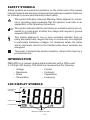
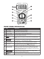
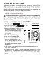
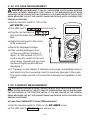
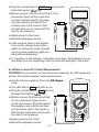
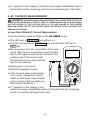
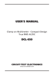
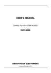
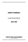
USER'S MANUAL
DIGITAL MULTIMETER
DMR-4200
CIRCUIT-TEST ELECTRONICS
www.circuittest.com
TABLE OF CONTENTS
SAFETY
Safety Information . . . . . . . . . . . . . . . . . . . . . . . . . . . . . . . . . . . . . . 2
Safety Symbols . . . . . . . . . . . . . . . . . . . . . . . . . . . . . . . . . . . . . . . . 3
INTRODUCTION
LCD Symbol Definitions . . . . . . . . . . . . . . . . . . . . . . . . . . . . . . . . . 3
Front Panel Description. . . . . . . . . . . . . . . . . . . . . . . . . . . . . . . . . . 4
SPECIFICATIONS
General . . . . . . . . . . . . . . . . . . . . . . . . . . . . . . . . . . . . . . . . . . . . . . 5
Ranges and Accuracy . . . . . . . . . . . . . . . . . . . . . . . . . . . . . . . . . . . 6
OPERATING INSTRUCTIONS
1. DC Voltage Measurement . . . . . . . . . . . . . . . . . . . . . . . . . . . . . 7
2. AC Voltage Measurement . . . . . . . . . . . . . . . . . . . . . . . . . . . . . 8
3. DC Current Measurement . . . . . . . . . . . . . . . . . . . . . . . . . . 8-10
a) less than 200mA DC current
b) 200mA or more DC current
4. AC Current Measurement . . . . . . . . . . . . . . . . . . . . . . . . . .10-11
a) less than 200mA DC current
b) 200mA or more AC current
5. Resistance Measurement . . . . . . . . . . . . . . . . . . . . . . . . . .11-12
6. Continuity Test . . . . . . . . . . . . . . . . . . . . . . . . . . . . . . . . . . . . . 12
7. Diode Test . . . . . . . . . . . . . . . . . . . . . . . . . . . . . . . . . . . . . . . . 13
8. Frequency Measurement . . . . . . . . . . . . . . . . . . . . . . . . . . . . 14
9. Temperature Measurement . . . . . . . . . . . . . . . . . . . . . . . . . . . 14
10. Capacitance Measurement . . . . . . . . . . . . . . . . . . . . . . . . . . . 15
11. Hold Function . . . . . . . . . . . . . . . . . . . . . . . . . . . . . . . . . . . . . 15
12. Battery Replacement. . . . . . . . . . . . . . . . . . . . . . . . . . . . . . . . 16
13. Fuse Replacement . . . . . . . . . . . . . . . . . . . . . . . . . . . . . . 16-17
MAINTENANCE . . . . . . . . . . . . . . . . . . . . . . . . . . . . . . . . . . . . . . . . . . . 18
ACCESSORIES . . . . . . . . . . . . . . . . . . . . . . . . . . . . . . . . . . . . . . . . . . . 18
WARRANTY. . . . . . . . . . . . . . . . . . . . . . . . . . . . . . . . . . . . . . . . . . . . . . 18
–1–
SAFETY INFORMATION
This meter is CUL and UL approved and conforms to IEC 61010-1 for Category
II 1000V. This meter is designed to be safe under the following conditions:
indoor use, altitude up to 2000m, temperature 5°C to 40°C, maximum relative
humidity 80% for temperatures up to 31°C decreasing linearly to 50% relative
humidity at 40°C and rated pollution degree 2. Caution and proper guidelines
must be followed for personal and product safety. Read this instruction
manual carefully and completely before using the meter. Lack of caution or
poor safety practices can result in serious injury or death.
• This meter is not recommended for high voltage industrial use; for
example, do not use for measurement on 440VAC or 600VAC industrial
power mains. The unit is intended for use with low energy circuits up to
600VDC / 600VAC or high energy circuits up to 250VAC / 250VDC only.
• Use caution when working above 60VDC or 30VAC RMS as these voltages pose a shock hazard.
• Always consider circuits to be energized. Never assume any equipment
to be de-energized.
• Always start with power off. Set the function switch to the correct setting
before making any measurements and do not change position of the
function switch during measurements.
• Never connect unit to AC or DC powered circuits when the function
switch is set to resistance, diode check or continuity ranges.
• Always disconnect the power when performing resistance, diode or
capacitance tests. Discharge capacitor before testing.
• Disconnect the live/positive test lead (red) prior to disconnecting the
common/negative test lead (black).
• When
appears on the display, change the battery immediately.
• Disconnect test leads from the meter before removing the battery or the
fuse.
• Do not operate the unit unless the case is completely closed.
• When using the test probes always keep fingers behind the finger
guards. Never touch the exposed probe tip.
• Always inspect the instrument, test leads and other accessories for
damage prior to use.
• Use only UL recognized test leads (included with this meter).
–2–
SAFETY SYMBOLS
Safety symbols and special annunciators on the meter and in this manual
indicate cautions and warnings of important operational procedures that must
be followed to ensure personal and product safety.
This symbol indicates a General Warning. When adjacent to a terminal or operating device indicates that the operator must refer to an
explanation in the Operating Instructions.
500V
MAX
This symbol indicates that the terminal(s) so marked must not be connected to a circuit point at which the voltage with respect to ground
exceeds 500V AC/DC.
This symbol adjacent to one or more terminals indicates them as
being associated with ranges that may in normal use, be subjected
to particularly hazardous voltages. For maximum safety, the meter
and its test leads should not be handled when these terminals are
energized.
This meter is protected by double insulation. Service this meter by a
professional only.
INTRODUCTION
DMR-4200 is a manual ranging digital multimeter with a 2000 count
3-1/2 Digit LCD display. This meter can measure/test the following:
–
–
–
–
Voltage
Resistance
Diode
Temperature
–
–
–
–
Current
Continuity
Capacitance
Frequency
LCD DISPLAY SYMBOLS
HAZARDOUS
VOLTAGE
DATA HOLD
LOW BATTERY
INDICATES RANGE SELECTED
–3–
7
1
8
2
CIRCUIT-TEST
DMR-4200
HOLD
3
POWER
200
2k
O H MS Ω
20k
200k
2M
TAN
CAPACI
200m
20µ
TS
VOL
DC
CE
20M
4
2µ
2
200
n
20
20n
200
700
P
AM
20
200m
2
20
20
AC 200m 2m
AMPS
6
20A
!
for 15 sec MAX
every 30 min
FUSED
20A MAX
TEMP
mA
°F
20kHz
TEMP
CAP
!
C
DC
200
20m
S
VO
LTS
2m
5
9
1000
2n
FRE
A
10
Q
11
V/Ω /F/ /
FUSED
200mA
MAX
1000 VDC
700 VAC
MAX
!
CAT II 1000V
500V
MAX
COM
FRONT PANEL DESCRIPTION
NO. ITEM
DESCRIPTION
1
LCD Display
3-1/2 digit 2000 count LCD Display
2
Power Button
Power ON/OFF push button switch
3
Function Switch
Function Switch to select measurement mode
4
Capacitance Jack
Insert the capacitor's two leads
5
20A Jack
Positive Input Jack to plug in red test lead for 20A measurement
only
6
TEMP/mA Jack
Positive Input Jack to plug in red test lead for current measurement
up to 200mA or ʻ+ʼ end of temperature adapter.
7
Backlight Button
Backlight display - will shut off automatically after 5 seconds
8
Hold Button
The displayed data will freeze and
will appear on the LCD.
Changes in the input signal will not change the display.
9
Test Lead Input
Indicating LEDs
Lighted LED indicates the correct jack to plug in the test lead for
the selected function. LED will turn off after the test lead is fully
inserted. If the test lead is incorrectly plugged in, the LED will start
blinking and buzzer will sound.
10
V/ /F/
Positive Input Jack to plug in red test lead for voltage, resistor,
frequency, continuity and diode check.
11
/
Jack
Jack
Plug in black test lead in all measurement modes, common ground
–4–
SPECIFICATIONS
GENERAL
Display:
Maximum Display:
Backlight Display:
Ranging:
Polarity:
3 1/2 digit 2000 count LCD
1999
5 seconds ON
Manual
Automatic, minus (-) sign indicates negative polarity, no sign for positive polarity
Measuring rate:
3 times/sec
Input impedance:
10M (DCV / ACV)
Diode Test:
Test current of 1.0 mA maximum
Continuity:
Audible signal sounds if resistance is less than
30
Over range indication: ʻIʼ is displayed
Operating Temp:
41 to 95° F (5 to 35° C)
Storage Temp:
14 to 122° F (-10 to 50° C)
Relative Humidity:
<75% Operating/Storage
Power Source:
1 x 9V Battery
Fuse:
0.5A/250V (5x20mm Fast Acting Ceramic),
15A/250V (6.3x32mm Fast Acting Ceramic)
Dimensions:
185(H) x 90(W) x 45(D) mm
(75/16 x 31/2 x 113/16")
Weight:
347g (12.25 oz)
Accessories included: One pair of test leads, 1 x 9V battery,
Userʼs manual
–5–
RANGES AND ACCURACY
FUNCTION
RANGE
RESOLUTION
ACCURACY
DC VOLTAGE
(DC V)
200mV
2V
20V
200V
1000V
100µV
1mV
10mV
100mV
1V
±(0.5% reading + 1 digit)
AC VOLTAGE
(AC V)
(40-400HZ)
2V
20V
200V
700V
1mV
10mV
100mV
1V
±(0.8% reading + 3 digits)
DC CURRENT
(DC A)
2mA
20mA
200mA
20A
1µA
10µA
100µA
10mA
±(0.8% reading + 1 digits)
AC CURRENT
(AC A)
(40-400HZ)
2mA
200mA
20A
1µA
100µA
10mA
±(1.0% reading + 3 digits)
±(1.8% reading + 3 digits)
±(3.0% reading + 7 digits)
RESISTANCE
200
2k
20k
200k
2M
20M
0.1
1
10
100
1k
10k
±(0.8% reading + 1 digit)
CAPACITANCE
2nF
20nF
200nF
2µF
20µF
1pF
10pF
100pF
1nF
10nF
±(2.5% reading + 3 digits)
FREQUENCY
20Hz-20KHz
10Hz
±(0.1% reading + 5 digits)
TEMP °F
0 to 500°F
1°F
±(1.0% reading + 4 digits)
±(0.8% reading + 2 digits)
±(1.2% reading + 3 digits)
±(1.2% reading + 1 digit)
±(2.0% reading + 5 digits)
±(1.0% reading + 2 digits)
NOTE: Accuracy consists of: (% reading i.e. accuracy of the measurement circuit +
digits i.e. accuracy of the analog to digital converter)
–6–
OPERATING INSTRUCTIONS
This meter comes with an exclusive patented technology featuring bright
LEDs indicating the correct input jack to plug-in the positive (red) test lead
for the selected function. The LED turns off after the test lead is completely
plugged in the correct jack. If the test lead is plugged in the wrong jack, the
LED will start flashing and the buzzer will start beeping.
1. DC VOLTAGE MEASUREMENT
WARNING: MAXIMUM INPUT IS 1000V DC. USE EXTREME CAUTION WHEN WORKING
WITH HIGH VOLTAGES. NEVER APPLY THE TEST LEAD TO THE MEASURING CIRCUIT WHEN
CHANGING THE POSITION OF THE FUNCTION SWITCH. IF YOU ARE UNSURE OF THE VOLTAGE
BEING MEASURED, SELECT THE HIGHEST RANGE AND REDUCE UNTIL A SATISFACTORY
READING IS OBTAINED.
➔ Set the function switch to 1000 on the DC VOLTS scale.
jack will turn on.
jack and
DMR-4200
HOLD
POWER
CE
O H MS Ω
P
AM
S
C
➔ If the reading displayed does
not have a sufficient number of
digits i.e. 00.2 Instead of 1.786,
set the function switch to the next
lower range. Repeat until you have
maximum digits possible without
displaying ʻIʼ.
VO
LTS
DC
➔ Read the displayed voltage.
CIRCUIT-TEST
+ DC –
TS
VOL
DC
➔ Apply the test leads to the circuit to be
measured. Ensure that the black
lead is connected to the negative
side of the circuit and red lead to
the positive.
TAN
➔ Plug the red test lead in V/ /F/ /
the black test lead in
jack.
CAPACI
➔ The LED next to V/ /F/ /
A
AC
AM
20A
PS
CAP
TEMP
FRE
Q
V/Ω /F/ /
TEMP
mA
CAT II 1000V
COM
➔ If the minus (-) sign appears it means the voltage is negative at the
point being measured.
➔ If ʻIʼ appears on the display, it indicates over-range. Immediately remove
test leads from the measuring circuit to avoid any damage to the meter.
The input voltage should not exceed the measurement capability of this
meter.
–7–
2. AC VOLTAGE MEASUREMENT
WARNING: MAXIMUM INPUT IS 700V AC. USE EXTREME CAUTION WHEN WORKING
WITH HIGH VOLTAGES. NEVER APPLY TEST LEADS TO THE MEASURING CIRCUIT WHEN
CHANGING THE POSITION OF THE FUNCTION SWITCH. IF YOU ARE UNSURE OF THE VOLTAGE
BEING MEASURED, SELECT THE HIGHEST RANGE AND REDUCE UNTIL A SATISFACTORY
READING IS OBTAINED.
➔ Set the function switch to 700 on the
AC VOLTS scale.
jack will turn on.
➔ Plug the red test lead in V/ /F/ /
jack and the black test lead in
jack.
DMR-4200
HOLD
POWER
O H MS Ω
CAPACI
TAN
TS
VOL
DC
CE
➔ Apply the test leads to the circuit
to be measured.
CIRCUIT-TEST
P
AM
VO
LTS
DC
➔ Read the displayed voltage.
S
➔ If the reading displayed does
not have a sufficient number of
digits, i.e. 002 instead of 2.1011,
set the function switch to the next
lower range. Repeat until you have
maximum digits possible without
displaying ʻIʼ.
C
➔ The LED next to V/ /F/ /
A
AC
AM
20A
TEMP
mA
PS
CAP
TEMP
FRE
Q
V/Ω /F/ /
CAT II 1000V
COM
➔ If ʻIʼ appears on the display, it indicates over-range. Immediately remove
test leads from the measuring circuit to avoid any damage to the meter.
The input voltage should not exceed the measurement capability of this
meter.
3. DC CURRENT MEASUREMENT
WARNING: WHEN MEASURING CURRENT REMOVE ALL POWER FROM THE CIRCUIT
BEING TESTED. NEVER APPLY THE TEST LEAD TO THE MEASURING CIRCUIT WHEN CHANGING THE POSITION OF THE FUNCTION SWITCH. IF YOU ARE UNSURE OF THE CURRENT
BEING MEASURED, SELECT THE HIGHEST RANGE AND REDUCE UNTIL A SATISFACTORY
READING IS OBTAINED.
a) Less than 200mA DC Current Measurement
➔ Set the function switch to 200m on the DC AMPS scale.
➔ The LED next to TEMP/mA jack will turn on.
–8–
➔ Plug the red test lead in TEMP/mA jack and the
black test lead in
jack.
CIRCUIT-TEST
DMR-4200
HOLD
+ DC –
POWER
CAPACI
TAN
TS
VOL
DC
CE
O H MS Ω
P
AM
➔ Apply power to the circuit.
VO
LTS
DC
➔ Remove power from the circuit that is to be
measured. Open up the circuit and
connect the black lead to the negative side and the red lead to the
positive side of the circuit so that
the test leads are in series with the
load to be measured.
C
S
A
AC
AM
➔ Read the displayed current.
TEMP
FRE
Q
CAP
20A
➔ If the numeral value in the display
is too small, change the function
switch to next lower range. Repeat
until you have maximum digits possible without displaying ʻIʼ.
PS
V/Ω /F/ /
CAT II 1000V
TEMP
mA
COM
➔ If ʻIʼ appears on the display, it indicates over-range. Immediately remove
test leads from the measuring circuit to avoid any damage to the meter.
b) 200mA or more DC Current Measurement
CAUTION! Do not exceed 15 seconds when measuring the 20A range and
wait for 30 minutes between each measurement.
➔ Set the function switch to 20 on the DC Amps
scale.
➔ The LED above 20A jack will turn on.
–9–
CE
TAN
TS
VOL
DC
➔ Read the displayed current.
HOLD
O H MS Ω
VO
LTS
P
AM
➔ Apply power to the circuit.
DMR-4200
POWER
DC
S
C
➔ Remove power from the circuit that
is to be measured. Open up the
circuit and connect the black lead to
the negative side and the red lead
to the positive side of the circuit so
that the test leads are in series with
the load to be measured.
CIRCUIT-TEST
+ DC –
CAPACI
➔ Plug the red test lead in 20A jack and
the black test lead in
jack.
A
AC
AM
20A
TEMP
mA
PS
CAP
TEMP
FRE
Q
V/Ω /F/ /
CAT II 1000V
COM
➔ If ʻIʼ appears on the display, it indicates over-range. Immediately remove
test leads from the measuring circuit to avoid any damage to the meter.
4. AC CURRENT MEASUREMENT
WARNING: WHEN MEASURING CURRENT REMOVE ALL POWER FROM THE CIRCUIT
BEING TESTED. NEVER APPLY THE TEST LEAD TO THE MEASURING CIRCUIT WHEN CHANGING THE POSITION OF THE FUNCTION SWITCH. IF YOU ARE UNSURE OF THE CURRENT
BEING MEASURED, SELECT THE HIGHEST RANGE AND REDUCE UNTIL A SATISFACTORY
READING IS OBTAINED.
a) Less than 200mA AC Current Measurement
➔ Set the function switch to 200m on the AC AMPS scale.
➔ The LED next to TEMP/mA jack will turn on.
➔ Plug the red test lead in TEMP/mA jack and the black test lead in
jack.
➔ Remove power from the circuit that is to be measured. Open up the circuit and connect the black
lead to the negative side and the red lead to the
positive side of the circuit so that
the test leads are in series with the
load to be measured.
DMR-4200
HOLD
POWER
O H MS Ω
CAPACI
TAN
TS
VOL
DC
CE
➔ Apply power to the circuit.
CIRCUIT-TEST
P
AM
S
C
➔ If the numeral value in the display
is too small, change the function
switch to next lower range. Repeat
until you have maximum digits possible without displaying ʻIʼ.
VO
LTS
DC
➔ Read the displayed current.
A
AC
AM
20A
TEMP
mA
PS
CAP
FR
TEMP
EQ
V/Ω /F/ /
CAT II 1000V
COM
➔ If ʻIʼ appears on the display, it indicates over-range. Immediately remove test leads from the measuring
circuit to avoid any damage to the meter.
– 10 –
b) 200mA or more AC Current Measurement
CAUTION! Do not exceed 15 seconds when measuring the 20A range and
wait for 30 minutes between each measurement.
➔ Set the function switch to 20 on the AC AMPS scale.
➔ The LED above 20A jack will turn on.
➔ Plug the red test lead in 20A jack and black test
lead in the
jack.
CIRCUIT-TEST
DMR-4200
HOLD
POWER
CAPACI
TAN
TS
VOL
DC
CE
O H MS Ω
P
AM
VO
LTS
DC
S
C
➔ Remove power from the circuit that is
to be measured. Open up the circuit
and connect the black lead to the
negative side and the red lead to
the positive side of the circuit so
that the test leads are in series with
the load to be measured.
A
AC
AM
➔ Apply power to the circuit.
PS
EQ
CAP
20A
➔ Read the displayed current.
FR
TEMP
V/Ω /F/ /
CAT II 1000V
TEMP
mA
COM
➔ If ʻIʼ appears on the display, it indicates
over-range. Immediately remove test
leads from the measuring circuit to avoid any damage to the meter.
5. RESISTANCE MEASUREMENT
HOLD
CE
O H MS Ω
TAN
CAPACI
VO
LTS
P
AM
➔ The LED next to V/ /F/ /
will turn on.
DMR-4200
POWER
DC
➔ Set the function switch to the
desired OHMS scale.
CIRCUIT-TEST
TS
VOL
DC
WARNING: NEVER CONNECT THE TEST LEAD TO ANY
VOLTAGE WHEN THE FUNCTION SWITCH IS SET TO . REMOVE
ALL POWER FROM THE CIRCUIT BEING TESTED WHEN CHECKING RESISTANCE. DISCHARGE ANY CHARGED CAPACITORS.
NEVER APPLY THE TEST LEAD TO THE MEASURING CIRCUIT
WHEN CHANGING THE POSITION OF THE FUNCTION SWITCH. IF YOU ARE UNSURE OF THE
RESISTOR
RESISTANCE BEING MEASURED, SELECT THE
HIGHEST RANGE AND REDUCE UNTIL A SATISFACTORY READING IS OBTAINED.
C
S
A
AC
AM
jack
20A
TEMP
mA
➔ Plug the red test lead in V/ /F/ /
jack and black test lead in
jack.
– 11 –
PS
CAP
TEMP
FRE
Q
V/Ω /F/ /
CAT II 1000V
COM
➔ Apply the test leads to the resistor being measured. If the resistor is part
of a circuit, it is necessary to disconnect one end of the resistor to avoid
any unwanted interference from the rest of the circuit.
➔ Read the displayed resistance.
NOTE:
• ‘I’ is also displayed when the inputs are not connected.
• When measuring resistance above 1M , the meter may take a few seconds to get
a stable reading.
• Never measure a resistor that has voltage on it.
6. CONTINUITY TEST
WARNING: NEVER CONNECT THE TEST LEADS TO ANY VOLTAGE WHEN THE FUNCTION SWITCH IS SET TO /
. REMOVE ALL POWER FROM THE CIRCUIT BEING TESTED
WHEN CHECKING RESISTANCE. DISCHARGE ANY CHARGED CAPACITORS.
.
jack will turn on.
HOLD
O H MS Ω
TS
VOL
DC
P
AM
S
A
AC
AM
20A
TEMP
mA
– 12 –
DMR-4200
POWER
DC
➔ The buzzer will sound if the
resistance is less than 30 and the
measured resistance value will be
displayed in ohms.
CIRCUIT-TEST
WIRE
VO
LTS
➔ Apply the test leads to the circuit.
jack and
C
➔ Plug the red test lead into V/ /F/ /
the black test lead into
jack.
CE
/
TAN
➔ The LED next to V/ /F/ /
CAPACI
➔ Set the function switch to
PS
CAP
TEMP
FRE
Q
V/Ω /F/ /
CAT II 1000V
COM
7. DIODE TEST
WARNING: NEVER CONNECT THE TEST LEAD TO ANY VOLTAGE WHEN THE FUNCTION
SWITCH IS SET TO /
. REMOVE ALL POWER FROM THE CIRCUIT BEING TESTED WHEN
PERFORMING THE DIODE TEST. DISCHARGE ANY CHARGED CAPACITORS.
Note: If the diode is part of a circuit, it is necessary to disconnect one end of the diode to avoid any unwanted interference
from the rest of the circuit. The value indicated in the display
during the diode check is the forward bias voltage.
.
jack
CIRCUIT-TEST
DMR-4200
HOLD
POWER
O H MS Ω
CAPACI
TAN
TS
VOL
DC
➔ Plug the red test lead into
V/ /F/ / jack and the black
test lead into
jack.
DC
P
AM
VO
LTS
/
S
C
➔ The LED next to V/ /F/ /
will turn on.
CE
➔ Set the function switch to
A
AC
AM
➔ Apply the test leads across the
diode terminals and note the
meter reading.
PS
TEMP
FRE
Q
CAP
20A
V/Ω /F/ /
CAT II 1000V
TEMP
mA
COM
➔ Reverse the diode and note this
reading. Based on the reading
the result can be evaluated as
follows:
DMR-4200
HOLD
POWER
CE
O H MS Ω
TAN
CAPACI
– If both readings are ʻIʼ, the
diode is open (defective)
CIRCUIT-TEST
TS
VOL
DC
– If one reading is around 0.5
and the other reading is ʻIʼ,
the diode is good
P
AM
VO
LTS
DC
– 13 –
C
S
– If both readings are very
small or 0 (zero), the diode is
shorted (defective)
A
AC
AM
20A
TEMP
mA
PS
CAP
TEMP
FRE
Q
V/Ω /F/ /
CAT II 1000V
COM
8. FREQUENCY MEASUREMENT
WARNING: NEVER MEASURE FREQUENCY ON A CIRCUIT
WITH MORE THAN 250V.
➔ Set the function switch to FREQ.
jack will turn on.
➔ Plug the red test lead in
V/ /F/ / jack and black test
lead in
jack.
CIRCUIT-TEST
DMR-4200
HOLD
POWER
TAN
TS
VOL
DC
CE
O H MS Ω
CAPACI
➔ Apply the test leads to the point of
measurement.
P
AM
VO
LTS
DC
S
➔ Read the displayed frequency.
C
➔ The LED next to V/ /F/ /
A
AC
AM
TEMP
PS
FRE
CAP
20A
Q
V/Ω /F/ /
CAT II 1000V
TEMP
mA
COM
9. TEMPERATURE MEASUREMENT
WARNING: REMOVE ALL VOLTAGE SOURCES FROM THE CIRCUIT TO BE TESTED
BEFORE TAKING A TEMPERATURE MEASUREMENT. DO NOT MEASURE TEMPERATURE OF
METAL PARTS WITH A VOLTAGE ON THEM.
NOTE: To measure temperature, ‘K’ Type Thermocouple (model no. TL-190) and
Thermocouple adapter (model no. TL-340) are required.
➔ Set the function switch to TEMP.
➔ The LED next to TEMP/mA jack will turn on.
CE
TS
VOL
DC
– 14 –
VO
LTS
P
AM
➔ The digital reading will display the value in
proper decimal point & value.
HOLD
O H MS Ω
DC
S
C
➔ Touch the probe tip to the component you are
testing and keep it there for about 30 seconds or
until the reading stabilizes.
DMR-4200
POWER
TAN
➔ Plug the ʻKʼ type thermocouple in this adapter.
CIRCUIT-TEST
CAPACI
➔ Observing the polarity, plug in the temperature
probe adapter with + inserted in TEMP/mA
jack and – in
jack.
A
AC
AM
20A
TEMP
mA
PS
CAP
TEMP
FRE
Q
V/Ω /F/ /
CAT II 1000V
COM
10. CAPACITANCE MEASUREMENT
WARNING: FULLY DISCHARGE THE CAPACITOR BY SHORTING THE CAPACITOR
LEADS TOGETHER BEFORE TESTING.
➔ Set the function switch to 20µ on the
CAPACITANCE scale.
jack.
DMR-4200
HOLD
POWER
TAN
TS
VOL
DC
CE
O H MS Ω
VO
LTS
P
AM
S
C
➔ If ʻIʼ appears on the display, the value of the
capacitor is over the maximum range of the
meter.
CIRCUIT-TEST
DC
➔ Read the value and unit shown on the display.
If the value does not have enough digits, turn
the function switch to a lower range. Repeat
until you have the maximum digits possible
without displaying ʻIʼ.
CAPACI
➔ Insert the capacitor leads into the
A
AC
AM
20A
PS
TEMP
FRE
Q
CAP
V/Ω /F/ /
CAT II 1000V
TEMP
mA
COM
CAPACITOR
11. HOLD FUNCTION
This function is used to hold a reading. When this pushbutton is pressed,
the data being displayed at the time will be ʻfrozenʼ in the display and will
appear in the display. Changes in the input signals will not change the display.
This function can be used in all measurement modes. Press the pushbutton
again to release this function and will disappear.
– 15 –
12. BATTERY REPLACEMENT
WARNING: DISCONNECT BOTH TEST LEADS FROM ANY SOURCE OF VOLTAGE BEFORE REMOVING THE BACK COVER. DO NOT OPERATE THE METER UNTIL THE BACK COVER
IS IN PLACE AND FASTENED SECURELY.
will appear in the display when the
battery drops below the operating voltage
and requires replacing.
➔ Turn off the meter and disconnect
both test leads.
➔ Remove the single screw securing
the battery/fuse cover and lift to
open.
➔ Replace 9V battery observing the
correct polarity.
➔ Replace the cover and tighten the screw.
13. FUSE REPLACEMENT
WARNING: DISCONNECT BOTH TEST LEADS FROM ANY SOURCE OF VOLTAGE
BEFORE REMOVING THE BACK COVER. DO NOT OPERATE THE METER UNTIL THE BACK
COVER IS IN PLACE AND FASTENED SECURELY.
a) 0.5 Amp Fast acting 5x20mm Fuse
➔ Turn off the meter and disconnect
both test leads.
➔ Remove the single screw securing the
battery/fuse cover and lift to open.
➔ Remove the battery.
➔ Gently pull the fuse from its holder by
pulling gently on the ribbon.
➔ Replace the blown fuse with a
CSA/UL listed fast acting fuse rated at
0.5A/250V only (with the same ribbon ring around the fuse).
Do not use a fuse which has higher rated value than specified or try to
bypass the fuse.
➔ Replace the battery and cover and tighten the screw.
– 16 –
b) 15 Amp Fast acting 6.3x32mm Ceramic Fuse (by a professional
person only)
➔ Turn off the meter and disconnect
both test leads.
➔ Remove the three screws at the back
of the case (one at the top and two at
the bottom).
➔ Remove the single screw securing
the battery/fuse cover and lift to
open.
➔ Remove the batteries.
➔ Carefully lift the top of the case away
from the bottom.
CAUTION: Lift the top case
carefully - do not break the
wires attached to the battery
compartment.
➔ Gently lift the battery compartment and move it through the
hole on the inner side of the meter.
➔ The 15 amp fuse is the larger
fuse on the bottom of the PC board,
which should now be in full view. Carefully remove the old fuse and
replace it with a new CSA/UL listed fast acting ceramic 15A/250V fuse
only.
– 17 –
MAINTENANCE
a) Always keep the meter dry.
b) Keep the meter clean. Wipe the case occasionally with a damp cloth.
Do not use chemicals, cleaning solvents or detergents.
c) Use and store the meter in recommended normal environmental
conditions. Extreme temperatures can shorten the life of the electronic
components.
d) Use only fresh batteries.
e) Remove the batteries when the meter is not being used for a long
period of time.
ACCESSORIES
Test Leads (TL-107)
Fuses: 5x20mm Fast Ceramic 0.5A/250V,
6.3x32mm Fast Ceramic 15A/250V
Battery: 1 x 9V
OPTIONAL:
ʻKʼ Type Thermocouple (TL-190)
Thermocouple Adapter (TL-340)
Test Leads with Screw-on Alligator Clips (TL-222)
LIMITED WARRANTY
Circuit-Test Electronics warrants to the original purchaser that this product
be free of defect in material or workmanship for a period of 2 years from the
date of purchase. Visit our website (www.circuittest.com) for information on
warranty service.
Any product which has been subjected to misuse or accidental damage is
excluded from the warranty. Except as stated above, Circuit-Test Electronics
makes no promises or warranties either expressed or implied including warranties of merchantability or the fitness for any particular purpose.
Register your product online at www.circuittest.com
CIRCUIT-TEST
ELECTRONICS
A division of R.P. Electronic Components Ltd.
www.circuittest.com
– 18 –