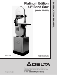
1
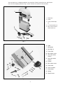
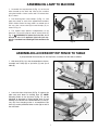
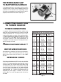
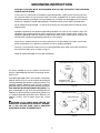
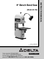
(Model 28-150)
PART NO. 900070-0010
Copyright © 2000 Delta Machinery
To learn more about DELTA MACHINERY
visit our website at: www.deltamachinery.com.
For Parts, Service, Warranty or other Assistance,
please call
ESPAÑOL: PÁGINA 25
1-888-848-5175 (In Canada call1 1-800-463-3582).
INSTRUCTION MANUAL
9" Bench Band Saw
SAFETY RULES
Woodworking can be dangerous if safe and proper operating procedures are not followed. As with all machinery, there
are certain hazards involved with the operation of the product. Using the machine with respect and caution will considerably lessen the possibility of personal injury. However, if normal safety precautions are overlooked or ignored, personal injury to the operator may result. Safety equipment such as guards, push sticks, hold-downs, featherboards,
goggles, dust masks and hearing protection can reduce your potential for injury. But even the best guard won’t make
up for poor judgment, carelessness or inattention. Always use common sense and exercise caution in the workshop.
If a procedure feels dangerous, don’t try it. Figure out an alternative procedure that feels safer. REMEMBER: Your personal safety is your responsibility.
This machine was designed for certain applications only. Delta Machinery strongly recommends that this machine not
be modified and/or used for any application other than that for which it was designed. If you have any questions relative to a particular application, DO NOT use the machine until you have first contacted Delta to determine if it can or
should be performed on the product.
Technical Service Manager
Delta Machinery
4825 Highway 45 North
Jackson, TN 38302-2468
(IN CANADA: 505 SOUTHGATE DRIVE, GUELPH, ONTARIO N1H 6M7)
WARNING: FAILURE TO FOLLOW THESE RULES MAY RESULT IN SERIOUS PERSONAL INJURY
17. USE RECOMMENDED ACCESSORIES. The use of
accessories and attachments not recommended by
Delta may cause hazards or risk of injury to persons.
18. R E D U C E T H E R I S K O F U N I N T E N T I O N A L
STARTING. Make sure switch is in “OFF” position
before plugging in power cord.
19. NEVER STAND ON TOOL. Serious injury could
occur if the tool is tipped or if the cutting tool is accidentally contacted.
20. CHECK DAMAGED PARTS. Before further use of
the tool, a guard or other part that is damaged should
be carefully checked to ensure that it will operate properly and perform its intended function – check for alignment of moving parts, binding of moving parts, breakage of parts, mounting, and any other conditions that
may affect its operation. A guard or other part that is
damaged should be properly repaired or replaced.
21. DIRECTION OF FEED. Feed work into a blade or
cutter against the direction of rotation of the blade or
cutter only.
22. NEVER LEAVE TOOL RUNNING UNATTENDED.
TURN POWER OFF. Don’t leave tool until it comes to a
complete stop.
23. DRUGS, ALCOHOL, MEDICATION. Do not operate
tool while under the influence of drugs, alcohol or any
medication.
24. MAKE SURE TOOL IS DISCONNECTED FROM
POWER SUPPLY while motor is being mounted, connected or reconnected.
25. THE DUST GENERATED BY CERTAIN WOODS
and wood products can be injurious to your health.
Always operate machinery in well ventilated areas and
provide for proper dust removal. Use wood dust collection systems whenever possible.
1. FOR YOUR OWN SAFETY, READ INSTRUCTION
MANUAL BEFORE OPERATING THE TOOL. Learn the
tool’s application and limitations as well as the specific
hazards peculiar to it.
2. KEEP GUARDS IN PLACE and in working order.
3. ALWAYS WEAR EYE PROTECTION.
4. REMOVE ADJUSTING KEYS AND WRENCHES.
Form habit of checking to see that keys and adjusting
wrenches are removed from tool before turning it “ON.”
5. KEEP WORK AREA CLEAN. Cluttered areas and
benches invite accidents.
6. DON’T USE IN DANGEROUS ENVIRONMENT.
Don’t use power tools in damp or wet locations, or
expose them to rain. Keep work area well-lighted.
7. KEEP CHILDREN AND VISITORS AWAY. All children and visitors should be kept a safe distance from
work area.
8. MAKE WORKSHOP CHILDPROOF – with padlocks, master switches, or by removing starter keys.
9. DON’T FORCE TOOL. It will do the job better and
be safer at the rate for which it was designed.
10. USE RIGHT TOOL. Don’t force tool or attachment
to do a job for which it was not designed.
11. WEAR PROPER APPAREL. No loose clothing,
gloves, neckties, rings, bracelets, or other jewelry to get
caught in moving parts. Nonslip footwear is recommended. Wear protective hair covering to contain long
hair.
12. ALWAYS USE SAFETY GLASSES. Wear safety
glasses. Everyday eyeglasses only have impact resistant
lenses; they are not safety glasses. Also use face or dust
mask if cutting operation is dusty.
13. SECURE WORK. Use clamps or a vise to hold work
when practical. It’s safer than using your hand and frees
both hands to operate tool.
14. DON’T OVERREACH. Keep proper footing and balance at all times.
15. MAINTAIN TOOLS IN TOP CONDITION.
Keep
tools sharp and clean for best and safest performance.
Follow instructions for lubricating and changing accessories.
16. DISCONNECT TOOLS before servicing and when
changing accessories such as blades, bits, cutters, etc.
26. WARNING: SOME DUST CREATED BY POWER
SANDING, SAWING, GRINDING, DRILLING, AND
OTHER CONSTRUCTION ACTIVITIES contains chemicals known to cause cancer, birth defects or other
reproductive harm. Some examples of these chemicals
are:
· lead from lead-based paints,
· crystalline silica from bricks and cement and other
masonry products, and
· arsenic and chromium from chemically-treated lumber.
2
Your risk from these exposures varies, depending on
how often you do this type of work. To reduce your
exposure to these chemicals: work in a well ventilated
area, and work with approved safety equipment, such as
those dust masks that are specially designed to filter out
microscopic particles.
SAVE THESE INSTRUCTIONS
ADDITIONAL SAFETY RULES FOR BAND SAWS
1. DO NOT OPERATE YOUR BAND SAW UNTIL it is
completely assembled and installed according to the
instructions.
17. ALWAY WEAR PROPER EAR PROTECTION.
18. AVOID awkward hand positions where a sudden slip
could cause a hand to move into the blade.
2. IF YOU ARE NOT thoroughly familiar with the operation of band saws, obtain advice from your supervisor,
instructor, or other qualified person.
19. DO NOT cut material that is too small to be safely
supported.
3. ALWAYS WEAR EYE PROTECTION.
20. MAKE SURE the blade teeth point downward
toward the table.
4. NEVER turn the machine “ON” before clearing the
table of all objects (tools, scrap pieces, etc.).
21. ALWAYS maintain proper adjustment of blade tension, blade guides, and blade support bearings.
5. NEVER start the band saw with the workpiece contacting the saw blade.
22. SHUT OFF the power and clean the table and work
area before leaving the machine.
6. ADJUST the upper guide assembly by no more than
1/4" above the material being cut.
23. SHOULD any part of your band saw be missing,
damaged, or fail in any way, or any electrical component
fail to perform properly, shut off switch and remove plug
from power supply outlet. Replace missing, damaged,
or failed parts before resuming operation.
7. MAKE SURE the blade tension and blade tracking
are properly adjusted.
8. ALWAYS keep hands and fingers away from the
blade.
24. THE USE of attachments and accessories not recommended by Delta may result in the risk of injuries.
9. CHECK for proper blade size and type.
10. DO NOT attempt to saw stock that does not have a
flat surface, unless a suitable support is used.
25. ADDITIONAL INFORMATION regarding the safe
and proper operation of this product is available from
the National Safety Council, 1121 Spring Lake Drive,
Itasca, IL 60143-3201 in the Accident Prevention
Manual for Industrial Operation and also in the Safety
Data Sheets provided by the NSC. Please also refer to
the American National Standards Institute ANSI 01.1
Safety Requirements for Woodworking Machinery and
the U.S. Depart-ment of Labor OSHA 1910.213
Regulations.
11. HOLD material firmly against the table and feed into
blade at a moderate speed.
12. TURN OFF machine if the material is to be backed
out of an uncompleted cut.
13. MAKE “relief” cuts before cutting long curves.
14. DO NOT remove jammed cut-off pieces until blade
has stopped.
26. DO NOT EXPOSE TO RAIN or use in damp location.
15. STOP the machine before removing scrap pieces
from the table.
27. When the tool is not in use, the switch chould be
locked in the “OFF” position to prevent unauthorized
ues.
16. NEVER perform layout, assembly, or set-up work on
the table while the machine is operating.
28. SAVE THESE INSTRUCTIONS. Refer to them frequently and use them to instruct other users.
SPECIFICATIONS
Motor:
1/3 H.P., 120V, Single Phase
Blade Length:
Blade Speed:
3000 SF/M
Capacities:
Table Size:
11-3/8" x 11-3/8"
Blade to frame 9"
Under Guide 3-3/4"
Table Groove:
1/4 "x 5/8"
Height:
29"
Table Tilt:
45° right
Length:
19-1/4"
Blade Width:
1/8 "minimum / 3/8 "maximum
Width:
12-1/2"
Weight:
33 lbs.
3
59-1/2"
Your new band saw is shipped complete in one container. Carefully unpack the saw and all loose
items from the shipping container. Figs. 2 and 3 illustrate the contents of the container.
1
1 - Band Saw
2 - Lamp
3 - Lamp cord clamps
(2)
4 - 1/4" lockwashers (2)
5 - M6 x 12mm cheese
head screws (2)
2
4
3
5
Fig. 2
6 - Table
7 - Miter gage
8 - M6 wing nut
6
9 - Flat washer
10 - M6 x 30mm screw
11 - 4mm Hex socket
wrench
12 - 3mm Hex socket
wrench
17
13 - Pointer
18
14 - M5 x 10mm screw
19
15 - Flat washer
15
16 - Lever assembly
8
16
9
10
11
7
17 - Pinion knob
18 - Spring
19 - Special screw
12
14
13
Fig. 3
4
ASSEMBLY INSTRUCTIONS
WARNING: FOR YOUR OWN SAFETY, DO NOT
CONNECT THE BAND SAW TO THE POWER
SOURCE UNTIL THE MACHINE IS COMPLETELY
ASSEMBLED AND YOU HAVE READ AND UNDERSTOOD THE ENTIRE OWNER’S MANUAL.
A
B
G
C
ASSEMBLING TABLE
TO MACHINE
E
1. Locate table locking lever (shown disassembled)
Fig. 4, flat washer (B) and 4mm wrench (C).
D
2. Using 4mm wrench (C) Fig. 4, supplied, remove
screw (D) and spring (E) from handle (A) and remove
handle from nut (G). Do not lose spring (E).
Fig. 4
H
3. Place table (H) Fig. 5, onto the band saw frame so
that stud (J) Fig. 6, and keepers (K) protrude through the
slot of trunnion (L) Fig. 7.
Fig. 5
4. While pressing in on stud (M) Fig. 8 with a pencil,
place flat washer (B) Fig. 7, onto stud and thread nut (G)
onto stud as shown in Fig. 4 and Fig. 7.
K
J
K
Fig. 6
L
M
B
G
Fig. 7
Fig. 8
5
5. Locate pinion knob (N) Fig. 9, spring (O), and special
screw (P).
N
O
P
Fig. 9
6. Position pinion knob (N) Fig. 10, onto the back of
saw so that the teeth on the pinion knob (N) engage the
teeth on the trunnion (R). Fasten in place with special
screw (P) and spring using the supplied 4mm wrench.
R
P
N
Fig. 10
7. Fasten pointer (S) Fig. 11, to the back of band saw
using the M5 x 10mm screw (T).
8. Using the supplied 4mm Hex socket wrench, reassemble table locking handle (F) Fig. 11, on stud and
replace screw and spring (D). NOTE: Handle (F) is springloaded and can be repositioned on the stud by pulling
out the handle and repositioning it on the nut.
D
F
S
T
Fig. 11
9. Insert M6 x 30mm screw (W) Fig. 12, down through
hole in table, as shown, and fasten in place by using M6
flat washer and M6 wing nut (X).
W
X
Fig. 12
6
ASSEMBLING LAMP TO MACHINE
1. Assemble the lamp bracket (A) Fig. 13, to the two
holes located on the back top cover of the machine
using the two M6 x 12mm screws and 1/4" lockwashers
(B) as shown.
E
2. Peel backing from cord clamps (C) Fig. 13, and
apply one clamp at each of the approximate locations
shown. Make certain the lamp cord is re-routed out of
the way, then secure cord (D) to cord clamps (C) as
shown in Fig. 13.
B
D
A
3. The flexible lamp operates independently of the
band saw. To turn the lamp on and off, rotate switch (E)
Fig. 13.
WARNING: To reduce the risk of fire, use a
40 watt or less A-15 appliance light bulb (not supplied). A standard household light bulb should not be
used.
F
C
C
Fig. 13
ASSEMBLING ACCESSORY RIP FENCE TO TABLE
If you purchased the Accessory 28-181 Rip Fence, assemble it to the table as follows:
1. With lever (A) Fig. 14, in the raised position as shown,
assemble rear clamp (B) of rip fence (C) over lip of
table (D).
C
A
B
D
Fig. 14
2. Lower the front of rip fence (C) Fig. 15, against the
table and push down on locking lever (A). NOTE:
Clamping action on the rip fence (C) Fig. 15, can be
tightened or loosened by lifting locking lever (A) and
rotating lever clockwise or counterclockwise as necessary until firm clamping action is accomplished. Rip
fence (C) can be positioned either to the right or left of
the saw blade.
C
A
Fig. 15
7
FASTENING BAND SAW
TO SUPPORTING SURFACE
A
If during operation there is any tendency for the machine
to tip over, slide, or “walk” on the supporting surface, the
machine must be secured to the supporting surface.
Four holes are provided in the band saw base for this
purpose, three of which are shown at (A) Fig. 16.
A
Fig. 16
CONNECTING BAND SAW
TO POWER SOURCE
POWER CONNECTIONS
A separate electrical circuit should be used for your
tools. This circuit should not be less than #12 wire and
should be protected with a 15 Amp fuse. Have a certified electrician replace or repair a worn cord immediately. Before connecting the motor to a power line, make
sure the switch is in the “OFF” position and be sure that
the electric current is of the same characteristics as
stamped on the motor nameplate. Running on low voltage will damage the motor.
MINIMUM GAUGE EXTENSION CORD
Gage of
Ampere Volts Total Length of
Rating
Cord in Feet Extension Cord
WARNING: DO NOT EXPOSE THE TOOL TO RAIN
OR OPERATE THE TOOL IN DAMP LOCATIONS.
MOTOR SPECIFICATIONS
Your band saw is wired for 110-120 volt, 60 Hz alternating current. Before connecting the band saw to the
power source, make sure the switch is in the “OFF”
position.
EXTENSION CORDS
Use proper extension cords. Make sure your extension
cord is in good condition and is a 3-wire extension cord
which has a 3-prong grounding type plug and a 3-pole
receptacle which will accept the tool’s plug. When using
an extension cord, be sure to use one heavy enough to
carry the current of the band saw. An undersized cord
will cause a drop in line voltage resulting in loss of power
and overheating. Fig. 17 shows the correct gage to use
depending on cord length. If in doubt, use the next
heavier gage. The smaller the gage number, the heavier
the cord.
0-6
0-6
0-6
0-6
120
120
120
120
up to 25
25-50
50-100
100-150
18 AWG
16 AWG
16 AWG
14 AWG
6-10
6-10
6-10
6-10
10-12
10-12
10-12
10-12
12-16
12-16
12-16
0-6
0-6
0-6
0-6
6-10
6-10
6-10
6-10
10-12
10-12
10-12
10-12
120
120
120
120
120
120
120
120
120
120
120
240
240
240
240
240
240
240
240
240
240
240
240
up to 25
25-50
50-100
100-150
up to 25
25-50
50-100
100-150
up to 25
25-50
18 AWG
16 AWG
14 AWG
12 AWG
16 AWG
16 AWG
14 AWG
12 AWG
14 AWG
12 AWG
12-16
12-16
12-16
240
240
240
GREATER THAN 50’ NOT RECOMMENDED
up to 50
50-100
100-200
200-300
up to 50
50-100
100-200
200-300
up to 50
50-100
100-200
200-300
18 AWG
16 AWG
16 AWG
14 AWG
18 AWG
16 AWG
14 AWG
12 AWG
16 AWG
16 AWG
14 AWG
12 AWG
up to 50
50-100
14 AWG
12 AWG
GREATER THAN 100’ NOT RECOMMENDED
Fig. 17
8
GROUNDING INSTRUCTIONS
CAUTION: THIS TOOL MUST BE GROUNDED WHILE IN USE TO PROTECT THE OPERATOR
FROM ELECTRIC SHOCK.
In the event of a malfunction or breakdown, grounding provides a path of least resistance for electric current to reduce the risk of electric shock. This tool is equipped with an electric cord having an
equipment-grounding conductor and a grounding plug. The plug must be plugged into a matching
outlet that is properly installed and grounded in accordance with all local codes and ordinances.
Do not modify the plug provided - if it will not fit the outlet, have the proper outlet installed by a qualified electrician.
Improper connection of the equipment-grounding conductor can result in risk of electric shock. The
conductor with insulation having an outer surface that is green with or without yellow stripes is the
equipment-grounding conductor. If repair or replacement of the electric cord or plug is necessary, do
not connect the equipment grounding conductor to a live terminal.
Check with a qualified electrician or service personnel if the grounding instructions are not completely understood, or if in doubt as to whether the tool is properly grounded.
Use only 3-wire extension cords that have 3-prong grounding types plugs and 3-hole receptacles
that accept the tool’s plug, as shown in Fig. 18.
Repair or replace damaged or worn cord immediately.
GROUNDED OUTLET BOX
CURRENT
CARRYING
PRONGS
This tool is intended for use on a normal 120-volt circuit
and has a grounded plug that looks like the plug illustrated in Fig. 18.
If a properly grounded outlet is not available, a temporary
adapter, shown in Fig. 19, may be used for connecting the
3-prong grounding type plug to a 2-prong receptacle. The
temporary adapter should be used only until a properly
grounded outlet can be installed by a qualified electrician.
THIS ADAPTER IS NOT APPLICABLE IN CANADA. The
green colored rigid ear, lug, or the like extending from the
adapter must be connected to a permanent ground such
as a properly grounded outlet box cover. Whenever the
adapter is used, it must be held in place with a metal
screw.
GROUNDING BLADE
IS LONGEST OF THE 3 BLADES
Fig. 18
GROUNDED OUTLET BOX
GROUNDING MEANS
ADAPTER
WARNING: IN ALL CASES, MAKE CERTAIN THE
RECEPTACLE IN QUESTION IS PROPERLY GROUNDED. IF YOU ARE NOT SURE, HAVE A CERTIFIED
ELECTRICIAN CHECK THE RECEPTACLE.
Fig. 19
9
OPERATING CONTROLS AND ADJUSTMENTS
STARTING AND
STOPPING SAW
The switch (A) Fig. 20, is located on the front side of the
band saw. To turn the saw “ON” move the switch (A) to
the up position. To turn the saw “OFF” move the switch
(A) to the down position.
A
Fig. 20
LOCKING SWITCH IN
THE “OFF” POSITION
When the tool is not in use, the switch be locked in the
“OFF” position. This can be done by grasping the switch
toggle (B) Fig. 21, and pulling it out of the switch, as
shown. With the switch toggle (B) removed, the switch will
not operate. However, should the switch toggle be
removed while the machine is running, the switch can be
turned “OFF” once, but cannot be restarted without
inserting the switch toggle (B).
B
Fig. 21
OPENING AND CLOSING
HINGED DOOR
For the purpose of making adjustments such as changing
the blade, tracking the blade, blade guide adjustments,
etc., the hinged door (B) Figs. 22 and 23, must be opened
as follows:
B
A
1. CAUTION: NEVER OPEN THE HINGED DOOR
WHEN THE MACHINE IS RUNNING.
2. Press in the two locking latches (A) Fig. 22, and swing
door (B) open.
Fig. 22
3. Fig. 23, illustrates door (B) in open position.
4. To close and fasten door (B) Figs. 22 and 23, press on
door directly over latches (A) Fig. 22, until latches snap
into the locking position.
B
10
Fig. 23
ADJUSTING
BLADE TENSION
A
B
Blades of 1/8", 1/4", and 3/8" wide by 59-1/2" in length
are available for use with your band saw. NOTE: The
blade tension must be adjusted to accommodate different blade widths in order to provide proper blade tracking, cutting performance and blade life.
C
1. DISCONNECT THE MACHINE FROM THE POWER
SOURCE.
2. After the desired blade is assembled to the two band
saw wheels, turn tension knob (A) Fig. 24, clockwise until
spring (B) begins to compress.
D
Fig. 24
3. Turn tension knob (A) Fig. 24, an additional 2-1/2
complete turns for 1/8" wide blades; 3 complete turns for
1/4" wide blades; and 4 complete turns for 3/8" wide
blades.
4. There is a convenient chart (C) Fig. 24, at the rear of
the band saw displaying blade choice and the minimum
radius which can be cut with each blade.
TRACKING THE BLADE
1. DISCONNECT THE MACHINE FROM THE POWER
SOURCE.
B
2. Before tracking the blade, make sure the blade
guides and blade support bearings are clear of the blade
so as not to interfere with the tracking adjustment. Also
make sure that the blade is tensioned properly. (Refer to
section “ADJUSTING BLADE TENSION”).
A
Fig. 25
3. Rotate upper wheel (A) Fig. 25, clockwise by hand
and check to see if the blade (B) rides true on the
approximate center of the two wheels.
4. If an adjustment is necessary, SLIGHTLY turn blade
tracking knob (D) Fig. 24, clockwise to move the blade
to the rear, and counterclockwise to move the blade to
the front. NOTE: Very little movement of the blade tracking adjusting knob (D) is necessary to permit the blade
to move.
B
C
ADJUSTING UPPER
BLADE GUIDE ASSEMBLY
The upper blade guide assembly (A) Fig. 26, should
always be no more than 1/4" above or as close as possible to the top surface of the workpiece being cut.
Loosen knob (B) Fig. 26, rotate knob (C) and position the
guide assembly (A) to the desired position. Then tighten
knob (B).
A
Fig. 26
11
ADJUSTING UPPER BLADE GUIDES AND
BLADE SUPPORT BEARING
IMPORTANT: BOTH THE UPPER AND LOWER BLADE GUIDES MUST BE PROPERLY ADJUSTED TO PREVENT
THE BLADE FROM TWISTING DURING OPERATION.
1. DISCONNECT THE MACHINE FROM THE POWER SOURCE.
2. NOTE: Upper blade guard (B) Fig. 27, is shown removed for clarity.
3. Loosen the two screws (C) Fig. 27, and adjust the blade guides (D) as close as possible to the sides of the saw
blade, being careful not to pinch the blade.Then tighten the two screws (C).
4. Loosen screw (E) Fig. 27, and move the guide bracket (F) in or out until the front edge of the guides (D) is just
behind the “gullets” of the blade teeth. Then tighten screw (E).
G
H
F
E
B
C
D C
Fig. 27
5. The upper blade support/thrust bearing (G) Fig. 27, prevents the saw blade from being pushed back too far when
cutting. The support bearing (G) should be adjusted approximately 1/32" behind the rear edge of the blade, so the back
edge of the blade overlaps the outside diameter of the ball bearing by approximately 1/8". To adjust, proceed as follows:
6. DISCONNECT THE MACHINE FROM THE POWER SOURCE.
7. Loosen screw (H) Fig. 27, and slide support bearing (G) in or out until it is approximately 1/32" behind the rear edge
of the saw blade. Then tighten screw (H).
8. The upper blade support bearing (G) Fig. 27, is set on an eccentric shaft. To change position of bearing (G), loosen
screw (H) Fig. 27, and using a straight screwdriver, rotate shaft (J) Fig. 28, until the blade properly overlaps the support
bearing. Then tighten screw (H).
J
Fig. 28
12
ADJUSTING LOWER BLADE GUIDES AND
BLADE SUPPORT BEARING
The lower blade guides and blade support bearing should be adjusted at the same time as the upper guides
and support bearings as follows:
1. DISCONNECT THE MACHINE FROM THE POWER SOURCE.
E
F
G
D
C
A
B
A
Fig. 29
G
Fig. 30
2. Loosen two screws (A) Fig. 29, and move guides (B) as close as possible to the sides of the blade, being
careful not to pinch the blade between the guides. Then tighten two screws (A).
3. The front edge of guide blocks (B) Fig. 29, should be adjusted so they are just behind the “gullets” of
the blade teeth by loosening screw (C), and moving assembly (D) in or out as necessary. Then tighten screw
(C).
4. The lower blade support bearing (E) Fig. 29, should be adjusted to support the rear of the blade during
the cutting operation and also prevent the blade from being pushed too far to the rear which could damage
the blade teeth. The support bearing (E) Fig. 29, should be set about 1/32" behind the blade by loosening
screw (F) Fig. 29, and moving shaft (G) in or out. Then tighten screw (F).
5. The lower blade support bearing (E) Fig. 29, should also be adjusted so the back edge of the blade overlaps the outside diameter of the ball bearing by approximately 1/8". The blade support bearing (E) is set on
an eccentric shaft.To change position of bearing (E), loosen screw (F) Fig. 29, and rotate shaft (G) Figs. 29
and 30, using a straight screwdriver until the blade properly overlaps the support bearing. Then tighten
screw (F) Fig.29.
13
TILTING THE TABLE
1. The table can be tilted 45 degrees to the right. To tilt
the table, loosen lock handle (A) Fig. 31, and turn knob
(B) clockwise until desired angle is established. Then
tighten lock handle (A). NOTE: The table lock handle (A)
can be repositioned by pulling out on the handle and
repositioning it on the nut located underneath the hub of
the handle. A scale (C) and pointer (D) are provided to
indicate the degree of tilt.
E
A
B
C
Fig. 31
D
ADJUSTING THE TABLE POSITIVE STOPS
Positive stops are provided for the table at the 90 and 45 degree angle to the blade. To check and
adjust the positive stops, proceed as follows:
MAKE CERTAIN THE MACHINE IS DISCONNECTED FROM THE POWER SOURCE.
1. Tilt the table to the 90 degree position as shown in Fig. 32, and tighten lock handle (A) Fig. 31.
Place a square (B) Fig. 32, on the table and against the blade and check to see if the blade is 90
degrees to the table surface. If an adjustment is necessary, proceed as follows:
2. Tilt the table slightly as shown in Fig. 31, to expose lock nut (E). Loosen lock nut and return table
to the 90° position. With the lock handle (A) loose, turn adjusting screw (F) Fig. 32, using the wrench (G)
provided until the blade is 90 degrees to the table. Then tighten lock nut (E) Fig. 32, and lock handle (A).
3. Tilt the table to the 45 degree position as shown in Fig. 33. Place a square (H) on the table and
against the blade and check to see if the blade is 45 degrees to the table surface. If an adjustment is
necessary, proceed as follows:
4. Loosen lock nut on adjustment screw (J) Fig. 33, located on the underside of the table. With lock
handle (A) Fig. 33, loose, turn adjustment screw (J) using wrench (G) provided until the blade is 45
degrees to the table. Then tighten lock handle (A), and lock nut on adjustment screw (J).
H
H
G
G
F
J
E
Fig. 32
Fig. 33
14
A
A
ADJUSTING BELT TENSION
If the drive belt on your band saw needs adjustment,
proceed as follows:
1. D I S C O N N E C T S A W F R O M T H E P O W E R
SOURCE.
Fig. 34
2. The belt (A) Fig. 34, drives the saw pulley from the
motor pulley. Correct tension of the belt (A) is when there
is approximately 1/4" deflection in the center span of the
belt (A) using light finger pressure. If belt tension needs
adjusted, loosen two screws (B) Fig. 35, and rotate motor
accordingly. Tighten screws (B) when adjustment is
completed.
B
B
Fig. 35
WHEEL BRUSHES
1. D I S C O N N E C T S A W F R O M T H E P O W E R
SOURCE.
1. Two wheel brushes (A) Fig. 36, are provided on the
machine to keep the tires free of any build-up of wood
chips. Adjustments can be made by loosening screws,
one of which is shown at (B) (which secure the brushes
to the machine) and adjusting brushes accordingly. Then
tighten screws (B).
A
B
A
Fig. 36
15
WRENCH STORAGE
The 3mm and 4mm adjustment wrenches (A) supplied
with your band saw can be conveniently stored inside
the wheel cover as shown in Fig. 37.
MITER GAGE
A miter gage (A) Fig. 38, is supplied with your band saw.
The miter gage body (C) can be adjusted up to 45
degrees right and left, by loosening lock knob (B), rotating miter gage body (C) to the desired angle, and tightening lock knob (B).
A
Fig. 37
BLADE CHANGING
To change blades, proceed as follows:
1. DISCONNECT SAW FROM THE POWER
SOURCE.
2. Press in door latches (A) Fig. 39, and open door (B)
as shown.
C
3. Loosen two screws (C) Fig. 40, and remove blade
guard (D).
4. Release tension on the band saw blade by turning
tension knob (E) Fig. 39 counterclockwise.
B
A
5. Remove table alignment screw (F) Fig. 41.
Fig. 38
6. Slip the blade off both wheels and guide it out
through the slot in the table.
E
7. Check the new blade to determine that the teeth will
point down toward the table when installed. IF NOT,
CAREFULLY TURN BLADE INSIDE OUT.
A
8. Place the new blade onto wheels and adjust blade
tension, blade guides and tracking as described previously in this manual.
B
9. Replace blade guard, which was removed in STEP 3,
and table alignment screw which was removed in
STEP 5.
A
10. Close door (B) Fig. 39, before operating saw.
Fig. 39
C
D
F
Fig. 40
Fig. 41
16
ACCESSORY RIP FENCE OPERATION AND ADJUSTMENTS
The accessory rip fence (A ) Fig. 42, can be moved along
the table surface by lifting lock lever (B) and sliding the
rip fence (A) to the desired location on the table. Push
down on lever (B) to firmly lock rip fence in position on
the table. When the rip fence (A) is locked to the band
saw table, it should be parallel to the miter gage slot (D).
If an adjustment is necessary, proceed as follows:
A
D
E
1. DISCONNECT MACHINE FROM THE POWER
SOURCE.
2. Loosen two screws (E) Fig. 42, and raise locking
lever (B).
B
3. While holding rip fence bracket (F) Fig. 42 firmly,
move the far end of the fence (A) until it is parallel with
the miter gage slot (D).
F
Fig. 42
4. Tighten two screws (E) Fig. 42, and push down on
locking lever (B).
5. Clamping action on the rip fence (A) Fig. 42, can
be tightened or loosened by lifting locking lever (B) and
rotating lever (B) clockwise or counterclockwise as
necessary.
DUST CHUTE
A
A built-in dust chute (A) Fig. 43, on your bench band saw
is equipped with a 1-1/2" I.D. opening that can easily be
connected to a dust collection system.
B
IDENTIFICATION PLATE
The identification plate (B) Fig. 43, is located at the rear
of the machine near the motor. The Model No. and Serial
No. are located on this plate. Please write these numbers
on the front cover of this manual for future reference.
Fig. 43
OPERATING THE BAND SAW
Before starting the machine, see that all adjustments are properly made and the guards are in
place. Turn the upper wheel by hand to make sure that everything is correct BEFORE turning on
the power.
Keep the top guide down close to the work at all times. Do not force the material against the
blade too hard. Light contact with the blade will permit easier following of the line and prevent
undue friction, heating and work-hardening of the blade at its back edge.
KEEP THE SAW BLADE SHARP and you will find that very little forward pressure is required
for average cutting. Move the stock against the blade steadily and no faster than will give an easy
cutting movement.
Avoid twisting the blade by trying to turn sharp corners. Remember, you must saw around corners.
17
CUTTING CURVES
When cutting curves, turn the stock carefully so that the blade follows without twisting. If a curve is so abrupt that
it is necessary to repeatedly back up and cut a new kerf, a narrower blade, a blade with more set, or additional
relief cuts Fig. 44, may be necessary to allow the blade to cut more efficiently. The more set a blade has, the easier it will allow the stock to be turned, but the cut is usually rougher than where a medium amount of set is used.
Fig. 44
In withdrawing the piece being cut, in order to change the cut, or for any other reason, the operator must be careful that he does not accidentally draw the blade off the wheels. In most cases, it is easier and safer to turn the
stock and saw out through the waste material, rather than try to withdraw the stock from the blade.
OPERATIONS
A
B
Fig. 45
Fig. 45 illustrates a typical cross-cutting operation using a miter gage. Notice
how the upper blade guide (A) assembly is set slightly above the work surface
(B).
18
Fig. 46
Fig. 46 illustrates a typical bevel cutting operation using a miter gage.
Fig. 47
Fig. 47 illustrates a typical resawing application using the accessory rip fence.
19
TROUBLESHOOTING GUIDE
In spite of how well a band saw is maintained, problems can occur. The following troubleshooting
guide will help you solve the more common problems:
Trouble: SAW WILL NOT START.
Probable Cause
Remedy
1. Saw not plugged in.
1. Plug in saw.
2. Fuse blown or circuit breaker tripped.
2. Replace fuse or reset circuit breaker.
3. Cord damaged.
3. Have cord replaced.
Trouble: BREAKER KICKS OUT FREQUENTLY.
Probable Cause
Remedy
1. Extension cord too light or too long.
1. Replace with adequate size cord.
2. Feeding stock too fast.
2. Feed stock more slowly.
3. Blade in poor condition (dull, warped, gummed).
3. Clean or replace blade.
4. Low voltage supply.
4. Contact your electric company.
Trouble: BAND SAW VIBRATES EXCESSIVELY.
Probable Cause
Remedy
1. Machine not mounted securely to workbench.
1. Tighten all mounting hardware.
2. Bench on uneven floor.
2. Reposition on flat level surface.
3. Irregular belt.
3. Replace belt.
4. Belt not tensioned correctly.
4. Adjust belt tension by moving motor.
5. Motor not fastened securely.
5. Tighten all mounting hardware.
Trouble: BAND SAW DOES NOT COME UP TO SPEED.
Probable Cause
Remedy
1. Extension cord too light or too long.
1. Replace with adequate size cord.
2. Low supply voltage.
2. Contact your electric company.
Trouble: BLADES BREAK.
Probable Cause
Remedy
1. Blade not tensioned properly.
1. Adjust blade tension.
2. Blade guides improperly adjusted.
2. Check and adjust blade guides.
3. Blade support bearing improperly adjusted.
3. Adjust blade support bearing.
4. Blade wheel tracking adjustment improperly set.
4. Check and adjust blade tracking.
5. Bad weld on blade.
5. Replace the blade.
6. Worn tires.
6. Replace tires.
7. Forcing wide blade around short radius.
7. Change to a narrower blade.
8. Dull blade or insufficient set.
8. Replace blade.
9. Upper blade guide set too high.
9. Set upper blade guide as close as possible to
work.
10. Continuous running of machine when not actually
cutting.
10. Turn off machine when not performing cutting
operation.
(continued on next page)
20
TROUBLESHOOTING GUIDE
(CONTINUED)
Trouble: BLADE WILL NOT TRACK.
Probable Cause
Remedy
1. Blade too loose
1. Adjust tension
2. Upper wheel not properly adjusted.
2. Adjust upper wheel.
3. Improper back-up bearing adjustment.
3. Adjust back-up.
Trouble: CUT DOES NOT AGREE WITH SETTING ON THE TILT SCALE.
Probable Cause
Remedy
1. Pointer out of adjustment
1. Adjust pointer.
Trouble: BLADE WILL NOT STAY ON WHEEL.
Probable Cause
Remedy
1. Blade not tensioned properly.
1. Adjust blade tension.
2. Blade guides improperly adjusted.
2. Check and adjust blade guides.
3. Blade support bearing improperly adjusted.
3. Adjust blade support bearing.
4. Blade wheel tracking adjustment improperly set.
4. Check and adjust blade tracking.
5. Bad weld on blade.
5. Replace the blade.
6. Worn tires.
6. Replace tires.
Trouble: BAND SAW MAKES UNSATISFACTORY CUTS.
Probable Cause
Remedy
1. Blade not tensioned properly.
1. Adjust blade tension.
2. Blade guides improperly adjusted.
2. Check and adjust blade guides.
3. Blade support bearing improperly set.
3. Adjust blade support bearing.
4. Blade wheel tracking adjustment improperly set.
4. Check and adjust blade tracking.
5. Bad weld on blade.
5. Replace the blade.
6. Worn tires.
6. Replace tires.
7. Incorrect blade for work being done.
7. Change the blade.
8. Dull blade or insufficient set.
8. Replace blade.
9. Upper blade guide set too high.
9. Set upper blade guide as close as possible to
work.
10. Continuous running of machine when not actually
cutting.
10. Turn off machine when not performing cutting
operation.
21
BAND SAW BLADES
A band saw blade is a delicate piece of steel that is subjected to tremendous strain. You can
obtain long use from a band saw blade if you give it fair treatment. Be sure you use blades of the
proper thickness, width and temper for the various types of material to be cut.
Always use the widest blade possible. Use the narrow blades only for sawing small, abrupt
curves and for fine, delicate work. This will save blades and will produce better work. Band saw
blades may be purchased, welded, set and sharpened ready for use. For cutting wood and similar materials, Delta can supply blades in widths of 1/8, 1/4, and 3/8 inches.
Any one of a number of conditions may cause a band saw blade to break. Blade breakage is, in
some cases, unavoidable, being the natural result of the peculiar stresses to which such blades
are subjected. It is, however, often due to avoidable causes, most often to lack of care or judgment on the part of the operator in mounting or adjusting the blade or guides. The most common
causes of blade breakage are:
(1) faulty alignments and adjustments of the guides;
(2) forcing or twisting a wide blade around a curve of short radius;
(3) feeding too fast;
(4) dullness of the teeth or absence of sufficient set;
(5) excessive tensioning of the blade;
(6) top guide set too high above the work being cut;
(7) using a blade with a lumpy or improperly finished braze or weld; and
(8) continuous running of the saw blade when not in use for cutting.
Blades for the new 28-150 9" Band Saw are 59-1/2 inches long.
Always use a sharp blade. Keep it free from gum and pitch. Clean frequently with a stiff fiber
brush.
Narrow blades are used for cutting small circles or curves while the wider blades are best suited
for straight cutting such as ripping.
Due to the low cost of blades, it is advisable to purchase new blades rather than attempt to have
them sharpened.
Make sure the blade guides are always adjusted properly as previously outlined.
Do not force or twist the blade around a curve or a very short radius.
Feed the work uniformly, allowing the blade to cut – do not feed too fast.
Do not apply excessive tension on blades. The tension is only necessary to drive the blade without slipping on the wheels. Narrow blades require less tension than wider blades.
22
NOTES
All Delta Machines and accessories are manufactured to high quality standards and are serviced by a network of Porter-Cable•Delta
Factory Service Centers and Delta Authorized Service Stations. To obtain additional information regarding your Delta quality product or
to obtain parts, service, warranty assistance, or the location of the nearest service outlet, please call 1-888-848-5175 (In Canada call 1800-463-3582).
Delta Building Trades and Home Shop Machinery
Two Year Limited Warranty
Delta will repair or replace, at its expense and at its option, any Delta machine, machine part, or machine
accessory which in normal use has proven to be defective in workmanship or material, provided that the customer returns the product prepaid to a Delta factory service center or authorized service station with proof
of purchase of the product within two years and provides Delta with reasonable opportunity to verify the
alleged defect by inspection. Delta may require that electric motors be returned prepaid to a motor manufacturer’s authorized station for inspection and repair or replacement. Delta will not be responsible for any
asserted defect which has resulted from normal wear, misuse, abuse or repair or alteration made or specifically authorized by anyone other than an authorized Delta Service facility or representative. Under no circumstances will Delta be liable for incidental or consequential damages resulting from defective products.
This warranty is Delta’s sole warranty and sets forth the customer’s exclusive remedy, with respect to defective products; all other warranties, express or implied, whether of merchantability, fitness for purpose, or otherwise, are expressly disclaimed by Delta.