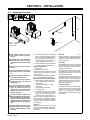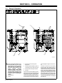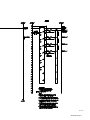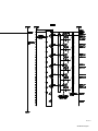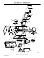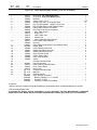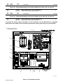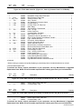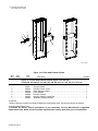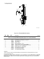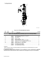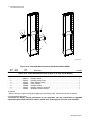
1
OM-263 001C 2014−06 Processes Multiprocess Welding Description Stationary Weld Fume Extractor ® FILTAIR Industrial Collector Series (230 Volt Models) Read And Save These Instructions File: Accessory Visit our website at www.MillerWelds.com From Miller to You Thank you and congratulations on choosing Miller. Now you can get the job done and get it done right. We know you don’t have time to do it any other way. That’s why when Niels Miller first started building arc welders in 1929, he made sure his products offered long-lasting value and superior quality. Like you, his customers couldn’t afford anything less. Miller products had to be more than the best they could be. They had to be the best you could buy. Today, the people that build and sell Miller products continue the tradition. They’re just as committed to providing equipment and service that meets the high standards of quality and value established in 1929. This Owner’s Manual is designed to help you get the most out of your Miller products. Please take time to read the Safety precautions. They will help you protect yourself against potential hazards on the worksite. We’ve made installation and operation quick and easy. With Miller you can count on years of reliable service with proper maintenance. And if for some reason the unit needs repair, there’s a Troubleshooting section that will help you figure out what the problem is. The Miller is the first welding parts list will then help you to decide the equipment manufacturer in exact part you may need to fix the problem. the U.S.A. to be registered to the ISO 9001 Quality System Warranty and service information for your Standard. particular model are also provided. Miller Electric manufactures a full line of welders and welding related equipment. For information on other quality Miller products, contact your local Miller distributor to receive the latest full line catalog or individual specification sheets. To locate your nearest distributor or service agency call 1-800-4-A-Miller, or visit us at www.MillerWelds.com on the web. Mil_Thank 2009−09 Working as hard as you do − every power source from Miller is backed by the most hassle-free warranty in the business. TABLE OF CONTENTS SECTION 1 − SAFETY PRECAUTIONS - READ BEFORE USING . . . . . . . . . . . . . . . . . . . . . . . . . . . . . . . . . 1-1. Symbol Usage . . . . . . . . . . . . . . . . . . . . . . . . . . . . . . . . . . . . . . . . . . . . . . . . . . . . . . . . . . . . . . . . . . . . . . . 1-2. Fume Extraction Hazards . . . . . . . . . . . . . . . . . . . . . . . . . . . . . . . . . . . . . . . . . . . . . . . . . . . . . . . . . . . . . . 1-3. Arc Welding And Plasma Cutting Hazards . . . . . . . . . . . . . . . . . . . . . . . . . . . . . . . . . . . . . . . . . . . . . . . . 1-4. Additional Symbols For Installation, Operation, And Maintenance . . . . . . . . . . . . . . . . . . . . . . . . . . . . . 1-5. California Proposition 65 Warnings . . . . . . . . . . . . . . . . . . . . . . . . . . . . . . . . . . . . . . . . . . . . . . . . . . . . . . 1-6. Principal Safety Standards . . . . . . . . . . . . . . . . . . . . . . . . . . . . . . . . . . . . . . . . . . . . . . . . . . . . . . . . . . . . . 1-7. EMF Information . . . . . . . . . . . . . . . . . . . . . . . . . . . . . . . . . . . . . . . . . . . . . . . . . . . . . . . . . . . . . . . . . . . . . SECTION 2 − MESURES DE SÉCURITÉ − EXTRACTION DES FUMÉES − À LIRE AVANT UTILISATION 2-1. Symboles utilisés . . . . . . . . . . . . . . . . . . . . . . . . . . . . . . . . . . . . . . . . . . . . . . . . . . . . . . . . . . . . . . . . . . . . . 2-2. Dangers en matière d’extraction des fumées . . . . . . . . . . . . . . . . . . . . . . . . . . . . . . . . . . . . . . . . . . . . . . 2-3. Dangers du soudage à l’arc et du coupage au plasma . . . . . . . . . . . . . . . . . . . . . . . . . . . . . . . . . . . . . . 2-4. Dangers supplémentaires en relation avec l’installation, le fonctionnement et la maintenance . . . . . 2-5. Proposition californienne 65 Avertissements . . . . . . . . . . . . . . . . . . . . . . . . . . . . . . . . . . . . . . . . . . . . . . 2-6. Principales normes de sécurité . . . . . . . . . . . . . . . . . . . . . . . . . . . . . . . . . . . . . . . . . . . . . . . . . . . . . . . . . 2-7. Informations relatives aux CEM . . . . . . . . . . . . . . . . . . . . . . . . . . . . . . . . . . . . . . . . . . . . . . . . . . . . . . . . . SECTION 3 − DEFINITIONS . . . . . . . . . . . . . . . . . . . . . . . . . . . . . . . . . . . . . . . . . . . . . . . . . . . . . . . . . . . . . . . . . . 3-1. Additional Safety Symbols And Definitions . . . . . . . . . . . . . . . . . . . . . . . . . . . . . . . . . . . . . . . . . . . . . . . . 3-2. Miscellaneous Symbols And Definitions . . . . . . . . . . . . . . . . . . . . . . . . . . . . . . . . . . . . . . . . . . . . . . . . . . SECTION 4 − SPECIFICATIONS . . . . . . . . . . . . . . . . . . . . . . . . . . . . . . . . . . . . . . . . . . . . . . . . . . . . . . . . . . . . . . 4-1. Introduction . . . . . . . . . . . . . . . . . . . . . . . . . . . . . . . . . . . . . . . . . . . . . . . . . . . . . . . . . . . . . . . . . . . . . . . . . 4-2. Standard Equipment . . . . . . . . . . . . . . . . . . . . . . . . . . . . . . . . . . . . . . . . . . . . . . . . . . . . . . . . . . . . . . . . . . 4-3. Serial Number And Rating Label Location . . . . . . . . . . . . . . . . . . . . . . . . . . . . . . . . . . . . . . . . . . . . . . . . 4-4. Fume Extractor Specifications . . . . . . . . . . . . . . . . . . . . . . . . . . . . . . . . . . . . . . . . . . . . . . . . . . . . . . . . . . 4-5. Performance Curves . . . . . . . . . . . . . . . . . . . . . . . . . . . . . . . . . . . . . . . . . . . . . . . . . . . . . . . . . . . . . . . . . . SECTION 5 − INSTALLATION . . . . . . . . . . . . . . . . . . . . . . . . . . . . . . . . . . . . . . . . . . . . . . . . . . . . . . . . . . . . . . . . 5-1. Selecting A Location . . . . . . . . . . . . . . . . . . . . . . . . . . . . . . . . . . . . . . . . . . . . . . . . . . . . . . . . . . . . . . . . . . 5-2. Clearance Requirements . . . . . . . . . . . . . . . . . . . . . . . . . . . . . . . . . . . . . . . . . . . . . . . . . . . . . . . . . . . . . . 5-3. Lifting The Equipment . . . . . . . . . . . . . . . . . . . . . . . . . . . . . . . . . . . . . . . . . . . . . . . . . . . . . . . . . . . . . . . . . 5-4. Mounting The Equipment . . . . . . . . . . . . . . . . . . . . . . . . . . . . . . . . . . . . . . . . . . . . . . . . . . . . . . . . . . . . . . 5-5. Connecting To Compressed Air Supply . . . . . . . . . . . . . . . . . . . . . . . . . . . . . . . . . . . . . . . . . . . . . . . . . . 5-6. Electrical Service Guide − Filtair 2000 . . . . . . . . . . . . . . . . . . . . . . . . . . . . . . . . . . . . . . . . . . . . . . . . . . . 5-7. Electrical Service Guide − Filtair 4000 . . . . . . . . . . . . . . . . . . . . . . . . . . . . . . . . . . . . . . . . . . . . . . . . . . . 5-8. Electrical Service Guide − Filtair 6000 . . . . . . . . . . . . . . . . . . . . . . . . . . . . . . . . . . . . . . . . . . . . . . . . . . . 5-9. Electrical Service Guide − Filtair 8000 . . . . . . . . . . . . . . . . . . . . . . . . . . . . . . . . . . . . . . . . . . . . . . . . . . . 5-10. Electrical Service Guide − Filtair 12000 . . . . . . . . . . . . . . . . . . . . . . . . . . . . . . . . . . . . . . . . . . . . . . . . . . 5-11. Making Electrical Connections To Unit Electrical Panel . . . . . . . . . . . . . . . . . . . . . . . . . . . . . . . . . . . . . SECTION 6 − OPERATION . . . . . . . . . . . . . . . . . . . . . . . . . . . . . . . . . . . . . . . . . . . . . . . . . . . . . . . . . . . . . . . . . . . 6-1. Theory Of Operation . . . . . . . . . . . . . . . . . . . . . . . . . . . . . . . . . . . . . . . . . . . . . . . . . . . . . . . . . . . . . . . . . . 6-2. Controls And Components . . . . . . . . . . . . . . . . . . . . . . . . . . . . . . . . . . . . . . . . . . . . . . . . . . . . . . . . . . . . . 6-3. Controller − General Information . . . . . . . . . . . . . . . . . . . . . . . . . . . . . . . . . . . . . . . . . . . . . . . . . . . . . . . . 6-4. Operating The Controller . . . . . . . . . . . . . . . . . . . . . . . . . . . . . . . . . . . . . . . . . . . . . . . . . . . . . . . . . . . . . . 6-5. Making Setpoint Adjustments . . . . . . . . . . . . . . . . . . . . . . . . . . . . . . . . . . . . . . . . . . . . . . . . . . . . . . . . . . . 6-6. Setpoint Adjustment Table . . . . . . . . . . . . . . . . . . . . . . . . . . . . . . . . . . . . . . . . . . . . . . . . . . . . . . . . . . . . . 6-7. Control Calibration . . . . . . . . . . . . . . . . . . . . . . . . . . . . . . . . . . . . . . . . . . . . . . . . . . . . . . . . . . . . . . . . . . . . 6-8. Changing From English To Metric Units . . . . . . . . . . . . . . . . . . . . . . . . . . . . . . . . . . . . . . . . . . . . . . . . . . 6-9. Changing Optional Settings . . . . . . . . . . . . . . . . . . . . . . . . . . . . . . . . . . . . . . . . . . . . . . . . . . . . . . . . . . . . 6-10. Prestart Checklist (Before Welding) . . . . . . . . . . . . . . . . . . . . . . . . . . . . . . . . . . . . . . . . . . . . . . . . . . . . . 1 1 1 2 4 5 5 5 6 6 6 7 9 11 11 11 12 12 12 13 13 13 13 14 15 16 16 17 17 18 19 20 20 21 21 22 23 24 24 25 26 27 28 29 30 31 32 33 TABLE OF CONTENTS SECTION 7 − USER SERVICING INSTRUCTIONS (MAINTENANCE) . . . . . . . . . . . . . . . . . . . . . . . . . . . . . . 34 7-1. Routine Maintenance . . . . . . . . . . . . . . . . . . . . . . . . . . . . . . . . . . . . . . . . . . . . . . . . . . . . . . . . . . . . . . . . . 34 7-2. Replacing Filters . . . . . . . . . . . . . . . . . . . . . . . . . . . . . . . . . . . . . . . . . . . . . . . . . . . . . . . . . . . . . . . . . . . . . 35 7-3. Emptying Particle Bin . . . . . . . . . . . . . . . . . . . . . . . . . . . . . . . . . . . . . . . . . . . . . . . . . . . . . . . . . . . . . . . . . 36 7-4. Overload Protection . . . . . . . . . . . . . . . . . . . . . . . . . . . . . . . . . . . . . . . . . . . . . . . . . . . . . . . . . . . . . . . . . . 37 7-5. Sprinkler Installation (Optional) . . . . . . . . . . . . . . . . . . . . . . . . . . . . . . . . . . . . . . . . . . . . . . . . . . . . . . . . . 38 7-6. Installing HEPA Filter Option . . . . . . . . . . . . . . . . . . . . . . . . . . . . . . . . . . . . . . . . . . . . . . . . . . . . . . . . . . . 39 SECTION 8 − TROUBLESHOOTING . . . . . . . . . . . . . . . . . . . . . . . . . . . . . . . . . . . . . . . . . . . . . . . . . . . . . . . . . . 40 8-1. Troubleshooting Table . . . . . . . . . . . . . . . . . . . . . . . . . . . . . . . . . . . . . . . . . . . . . . . . . . . . . . . . . . . . . . . . . 40 SECTION 9 − ELECTRICAL DIAGRAMS . . . . . . . . . . . . . . . . . . . . . . . . . . . . . . . . . . . . . . . . . . . . . . . . . . . . . . . 42 SECTION 10 − PARTS LIST . . . . . . . . . . . . . . . . . . . . . . . . . . . . . . . . . . . . . . . . . . . . . . . . . . . . . . . . . . . . . . . . . . 62 Figure 10-1. Filtair 2000 Assembly . . . . . . . . . . . . . . . . . . . . . . . . . . . . . . . . . . . . . . . . . . . . . . . . . . . . . . . . . . . . 62 Figure 10-2. Filtair 2000 Controller . . . . . . . . . . . . . . . . . . . . . . . . . . . . . . . . . . . . . . . . . . . . . . . . . . . . . . . . . . . . 64 Figure 10-3. Filtair 2000 Manifold Assembly . . . . . . . . . . . . . . . . . . . . . . . . . . . . . . . . . . . . . . . . . . . . . . . . . . . . 66 Figure 10-4. Filtair 2000 Exhaust Plenum . . . . . . . . . . . . . . . . . . . . . . . . . . . . . . . . . . . . . . . . . . . . . . . . . . . . . . 67 Figure 10-5. Filtair 2000 Exhaust Plenum w/HEPA Filter . . . . . . . . . . . . . . . . . . . . . . . . . . . . . . . . . . . . . . . . . . 68 Figure 10-6. Filtair 4000 Main Assembly . . . . . . . . . . . . . . . . . . . . . . . . . . . . . . . . . . . . . . . . . . . . . . . . . . . . . . . 70 Figure 10-7. Filtair 4000 Controller . . . . . . . . . . . . . . . . . . . . . . . . . . . . . . . . . . . . . . . . . . . . . . . . . . . . . . . . . . . . 73 Figure 10-8. Filtair 4000 Manifold Assembly . . . . . . . . . . . . . . . . . . . . . . . . . . . . . . . . . . . . . . . . . . . . . . . . . . . . 75 Figure 10-9. Filtair 4000 Exhaust Plenum . . . . . . . . . . . . . . . . . . . . . . . . . . . . . . . . . . . . . . . . . . . . . . . . . . . . . . 76 Figure 10-10. Filtair 4000 Exhaust Plenum w/HEPA Filter . . . . . . . . . . . . . . . . . . . . . . . . . . . . . . . . . . . . . . . . . 77 Figure 10-11. Filtair 6000 Main Assembly . . . . . . . . . . . . . . . . . . . . . . . . . . . . . . . . . . . . . . . . . . . . . . . . . . . . . . 78 Figure 10-12. Filtair 6000 Controller . . . . . . . . . . . . . . . . . . . . . . . . . . . . . . . . . . . . . . . . . . . . . . . . . . . . . . . . . . . 80 Figure 10-13. Filtair 6000 Manifold Assembly . . . . . . . . . . . . . . . . . . . . . . . . . . . . . . . . . . . . . . . . . . . . . . . . . . . 82 Figure 10-14. Filtair 6000 Exhaust Plenum . . . . . . . . . . . . . . . . . . . . . . . . . . . . . . . . . . . . . . . . . . . . . . . . . . . . . 83 Figure 10-15. Filtair 6000 Exhaust Plenum w/HEPA Filter . . . . . . . . . . . . . . . . . . . . . . . . . . . . . . . . . . . . . . . . . 84 Figure 10-16. Filtair 8000 Main Assembly . . . . . . . . . . . . . . . . . . . . . . . . . . . . . . . . . . . . . . . . . . . . . . . . . . . . . . 86 Figure 10-17. Filtair 8000 Controller . . . . . . . . . . . . . . . . . . . . . . . . . . . . . . . . . . . . . . . . . . . . . . . . . . . . . . . . . . . 88 Figure 10-18. Filtair 8000 Manifold Assembly . . . . . . . . . . . . . . . . . . . . . . . . . . . . . . . . . . . . . . . . . . . . . . . . . . . 90 Figure 10-19. Filtair 8000 Exhaust Plenums (All Models Without HEPA) . . . . . . . . . . . . . . . . . . . . . . . . . . . . . 91 Figure 10-20. Filtair 8000 Exhaust Plenum w/HEPA Filter . . . . . . . . . . . . . . . . . . . . . . . . . . . . . . . . . . . . . . . . . 92 Figure 10-21. Filtair 12000 Main Assembly . . . . . . . . . . . . . . . . . . . . . . . . . . . . . . . . . . . . . . . . . . . . . . . . . . . . . 94 Figure 10-22. Filtair 12000 Controller . . . . . . . . . . . . . . . . . . . . . . . . . . . . . . . . . . . . . . . . . . . . . . . . . . . . . . . . . . 96 Figure 10-23. Filtair 12000 Manifold Assembly . . . . . . . . . . . . . . . . . . . . . . . . . . . . . . . . . . . . . . . . . . . . . . . . . . 98 Figure 10-24. Filtair 12000 Exhaust Plenum . . . . . . . . . . . . . . . . . . . . . . . . . . . . . . . . . . . . . . . . . . . . . . . . . . . . 99 Figure 10-25. Filtair 12000 Exhaust Plenum w/HEPA Filter . . . . . . . . . . . . . . . . . . . . . . . . . . . . . . . . . . . . . . . 100 WARRANTY SECTION 1 − SAFETY PRECAUTIONS - READ BEFORE USING fume 2013−09 7 Protect yourself and others from injury — read, follow, and save these important safety precautions and operating instructions. 1-1. Symbol Usage DANGER! − Indicates a hazardous situation which, if not avoided, will result in death or serious injury. The possible hazards are shown in the adjoining symbols or explained in the text. Indicates a hazardous situation which, if not avoided, could result in death or serious injury. The possible hazards are shown in the adjoining symbols or explained in the text. NOTICE − Indicates statements not related to personal injury. Indicates special instructions. This group of symbols means Warning! Watch Out! ELECTRIC SHOCK, MOVING PARTS, and HOT PARTS hazards. Consult symbols and related instructions below for necessary actions to avoid the hazards. 1-2. Fume Extraction Hazards The symbols shown below are used throughout this manual to call attention to and identify possible hazards. When you see the symbol, watch out, and follow the related instructions to avoid the hazard. The safety information given below is only a summary of the more complete safety information found in the Safety Standards listed in Section 1-6. Read and follow all Safety Standards. Only qualified persons should install, operate, maintain, and repair this unit. During operation, keep everybody, especially children, away. FUME EXTRACTOR MISUSE can be hazardous. Welding produces fumes and gases. Breathing these fumes and gases can be hazardous to your health. Combustible materials may ignite and cause fire and explosion. Read and follow these instructions and the safety labels carefully. The fume extractor helps protect the user from specific airborne contaminants but must be used correctly to be fully effective. Have an industrial hygienist test the air in your facility to ensure the fume extractor provides adequate protection from contaminants in your environment. If you have questions about the extractor, see equipment label and consult your Safety Director and a certified Industrial Hygienist. Follow all applicable ANSI, OSHA, CSA, UL, and other regulatory guidelines pertaining to the use of fume extractors and the recirculation of filtered air. Portions of fume collection equipment, including the clean- and dirty-air plenums, may be considered OSHA Confined Spaces. Refer to the appropriate OSHA regulations to determine if a specific installation is a confined space and if a permit program is required. Do not use the fume extractor without an approved and properly installed spark guard unless the unit is designed and intended to be used without one. Without the spark guard, welding sparks may ignite a non-fire retardant filter or fume collected on the filter, or damage the filter and allow unfiltered air into the breathing zone. Do not allow sparks or any burning materials to enter the hood or duct of the fume extractor. Only use the fume extractor to extract weld fumes. Do not use the fume extractor to extract hot gases (above 140°F/60°C) wood or cement dust, engine exhaust, liquid vapors, explosive materials, aggressive fumes (acid), fumes from burning objects, or fumes from cleaning, cutting, gouging, grinding, painting, flame spraying, sand blasting, or other non−welding operations. Fumes from some welding operations may be combustible. Do not install or operate fume extractor where combustible weld fumes may be present unless a fire/and/or explosion protection system is present that has been selected and approved by a qualified person familiar with applicable codes and fire/explosion protection systems. Use the fume extractor only in atmospheres for which it is recommended. Do not use the extractor where contaminant levels are unknown or are immediately dangerous to life, or where the contaminant levels exceed the fume extractor specifications. Do not weld until you are sure the fume extractor is correctly assembled and working properly. Before each use, inspect the fume extractor for damage and verify it operates properly. Dangerous contaminants may not smell or be visible. Leave the area immediately if you notice the following: a. Breathing becomes difficult. b. You experience dizziness, impaired vision, or eye, nose, or mouth irritation. c. The equipment is damaged. d. Air flow decreases or stops. e. If you think the equipment is not supplying adequate protection. Do not repair, modify, or disassemble the fume extractor or use with parts or accessories not supplied by the manufacturer. Use only approved components from the manufacturer. Replace damaged or plugged filter. Do not wash or reuse filter, or clean filter by tapping or with compressed air, unless specifically instructed by the manufacturer in the Owner’s Manual (filter element may be damaged). Do not breathe the particles collected by the fume extractor. Wear approved safety equipment (respirator, gloves, long sleeve shirt) when performing filter maintenance. Dispose of used filter element and collected particles according to local, state, and federal requirements. Read and understand the Safety Data Sheets (SDSs) and the manufacturer’s instructions for adhesives, coatings, cleaners, consumables, coolants, degreasers, fluxes, and metals. The fume extractor must be used with the extraction arm, hoses, filter, and other components recommended by the manufacturer. ELECTRIC SHOCK can kill. Touching live electrical parts can cause fatal shocks or severe burns. The input power circuit and machine internal circuits are also live when power is on. Incorrectly installed or improperly grounded equipment is a hazard. Do not touch live electrical parts. Disconnect input power before installing or servicing this equipment. Lockout/tagout input power according to OSHA 29 CFR 1910.147 (see Safety Standards). Properly install, ground, and operate this equipment according to its Owner’s Manual and national, state, and local codes. Always verify the supply ground − check and be sure that input power cord ground wire is properly connected to ground terminal in disconnect box or that cord plug is connected to a properly grounded receptacle outlet. Frequently inspect input power cord and ground conductor for damage or bare wiring – replace immediately if damaged – bare wiring can kill. OM-263 001 Page 1 FALLING EQUIPMENT can injure. Use equipment of adequate capacity to lift and support unit. If using lift forks to move unit, be sure forks are long enough to extend beyond opposite side of unit. Keep equipment (cables and cords) away from moving vehicles when working from an aerial location. Follow the guidelines in the Applications Manual for the Revised NIOSH Lifting Equation (Publication No. 94−110) when manually lifting heavy parts or equipment. MOVING PARTS can injure. Keep away from moving parts such as fans. Keep all doors, panels, covers, and guards closed and securely in place. Have only qualified persons remove doors, panels, covers, or guards for maintenance and troubleshooting as necessary. Reinstall doors, panels, covers, or guards when maintenance is finished and before reconnecting input power. FIRE OR EXPLOSION hazard. Do not install or place unit on, over, or near combustible surfaces. Do not install unit near flammables. Do not overload building wiring − be sure power supply system is properly sized, rated, and protected to handle this unit. READ INSTRUCTIONS. Read and follow all labels and the Owner’s Manual carefully before installing, operating, or servicing unit. Read the safety information at the beginning of the manual and in each section. Use only genuine replacement parts from the manufacturer. Perform maintenance and service according to the Owner’s Manuals, industry standards, and national, state, and local codes. 1-3. Arc Welding And Plasma Cutting Hazards ELECTRIC SHOCK can kill. Frequently inspect input power cord for damage or bare wiring − replace cord immediately if damaged − bare wiring can kill. Touching live electrical parts can cause fatal shocks or severe burns. The electrode and work circuit is electrically live whenever the output is on. The input power circuit and machine internal circuits are also live when power is on. In semiautomatic or automatic wire welding, the wire, wire reel, drive roll housing, and all metal parts touching the welding wire are electrically live. Incorrectly installed or improperly grounded equipment is a hazard. Turn off all equipment when not in use. Do not touch live electrical parts. Wear dry, hole-free insulating gloves and body protection. Insulate yourself from work and ground using dry insulating mats or covers big enough to prevent any physical contact with the work or ground. Do not use AC output in damp areas, if movement is confined, or if there is a danger of falling. Use AC output ONLY if required for the welding or cutting process. If AC output is required, use remote output control if present on unit. Additional safety precautions are required when any of the following electrically hazardous conditions are present: in damp locations or while wearing wet clothing; on metal structures such as floors, gratings, or scaffolds; when in cramped positions such as sitting, kneeling, or lying; or when there is a high risk of unavoidable or accidental contact with the workpiece or ground. For these conditions, use the following equipment in order presented: 1) a semiautomatic DC constant voltage (wire) welder, 2) a DC manual (stick) welder, or 3) an AC welder with reduced open-circuit voltage. In most situations, use of a DC, constant voltage wire welder is recommended. And, do not work alone! Disconnect input power or stop engine before installing or servicing this equipment. Lockout/tagout input power according to OSHA 29 CFR 1910.147 (see Safety Standards). Properly install, ground, and operate this equipment according to its Owner’s Manual and national, state, and local codes. Always verify the supply ground − check and be sure that input power cord ground wire is properly connected to ground terminal in disconnect box or that cord plug is connected to a properly grounded receptacle outlet. When making input connections, attach proper grounding conductor first − double-check connections. Keep cords dry, free of oil and grease, and protected from hot metal and sparks. OM-263 001 Page 2 Do not use worn, damaged, undersized, or poorly spliced cables. Do not drape cables over your body. If earth grounding of the workpiece is required, ground it directly with a separate cable. Do not touch electrode if you are in contact with the work, ground, or another electrode from a different machine. Do not touch electrode holders connected to two welding machines at the same time since double open-circuit voltage will be present. Use only well-maintained equipment. Repair or replace damaged parts at once. Maintain unit according to manual. Wear a safety harness if working above floor level. Keep all panels and covers securely in place. Clamp work cable with good metal-to-metal contact to workpiece or worktable as near the weld as practical. Insulate work clamp when not connected to workpiece to prevent contact with any metal object. Do not connect more than one electrode or work cable to any single weld output terminal. Disconnect cable for process not in use. SIGNIFICANT DC VOLTAGE exists in inverter power sources AFTER removal of input power. Turn Off inverter, disconnect input power, and discharge input capacitors according to instructions in Maintenance Section before touching any parts. HOT PARTS can burn. Do not touch hot parts bare handed. Allow cooling period before working on equipment. To handle hot parts, use proper tools and/or wear heavy, insulated welding gloves and clothing to prevent burns. FUMES AND GASES can be hazardous. Do not weld or cut where the atmosphere may contain flammable dust, gas, or liquid vapors (such as gasoline). Welding and cutting produces fumes and gases. Breathing these fumes and gases can be hazardous to your health. Connect work cable to the work as close to the welding or cutting area as practical to prevent welding or cutting current from traveling long, possibly unknown paths and causing electric shock, sparks, and fire hazards. Keep your head out of the fumes. Do not breathe the fumes. Do not use welder to thaw frozen pipes. If inside, ventilate the area and/or use local forced ventilation at the arc to remove welding and cutting fumes and gases. The recommended way to determine adequate ventilation is to sample for the composition and quantity of fumes and gases to which personnel are exposed. Remove stick electrode from holder or cut off welding wire at contact tip when not in use. If ventilation is poor, wear an approved air-supplied respirator. Wear body protection made from durable, flame−resistant material (leather, heavy cotton, wool). Body protection includes oil-free clothing such as leather gloves, heavy shirt, cuffless trousers, high shoes, and a cap. Read and understand the Safety Data Sheets (SDSs) and the manufacturer’s instructions for adhesives, coatings, cleaners, consumables, coolants, degreasers, fluxes, and metals. Remove any combustibles, such as a butane lighter or matches, from your person before doing any welding or cutting. Work in a confined space only if it is well ventilated, or while wearing an air-supplied respirator. Always have a trained watchperson nearby. Welding and cutting fumes and gases can displace air and lower the oxygen level causing injury or death. Be sure the breathing air is safe. Use only correct fuses or circuit breakers. Do not oversize or bypass them. Do not weld or cut in locations near degreasing, cleaning, or spraying operations. The heat and rays of the arc can react with vapors to form highly toxic and irritating gases. Do not weld or cut on coated metals, such as galvanized, lead, or cadmium plated steel, unless the coating is removed from the weld area, the area is well ventilated, and while wearing an air-supplied respirator. The coatings and any metals containing these elements can give off toxic fumes if welded. ARC RAYS can burn eyes and skin. Arc rays from welding and cutting processes produce intense visible and invisible (ultraviolet and infrared) rays that can burn eyes and skin. Sparks fly off from the weld. Wear an approved welding helmet fitted with a proper shade of filter lenses to protect your face and eyes from arc rays and sparks when welding, cutting, or watching (see ANSI Z49.1 and Z87.1 listed in Safety Standards). Wear approved safety glasses with side shields under your helmet. Use protective screens or barriers to protect others from flash, glare and sparks; warn others not to watch the arc. Wear body protection made from durable, flame−resistant material (leather, heavy cotton, wool). Body protection includes oil-free clothing such as leather gloves, heavy shirt, cuffless trousers, high shoes, and a cap. WELDING AND CUTTING can cause fire or explosion. Welding or cutting on closed containers, such as tanks, drums, or pipes, can cause them to blow up. Sparks can fly off from the welding or cutting arc. The flying sparks, hot workpiece, and hot equipment can cause fires and burns. Accidental contact of electrode to metal objects can cause sparks, explosion, overheating, or fire. Check and be sure the area is safe before doing any welding or cutting. Remove all flammables within 35 ft (10.7 m) of the welding or cutting arc. If this is not possible, tightly cover them with approved covers. Do not weld or cut where flying sparks can strike flammable material. Protect yourself and others from flying sparks and hot metal. Be alert that welding sparks and hot materials from welding and cutting can easily go through small cracks and openings to adjacent areas. Watch for fire, and keep a fire extinguisher nearby. Be aware that welding or cutting on a ceiling, floor, bulkhead, or partition can cause fire on the hidden side. Do not weld or cut on containers that have held combustibles, or on closed containers such as tanks, drums, or pipes unless they are properly prepared according to AWS F4.1 and AWS A6.0 (see Safety Standards). After completion of work, inspect area to ensure it is free of sparks, glowing embers, and flames. Follow requirements in OSHA 1910.252 (a) (2) (iv) and NFPA 51B for hot work and have a fire watcher and extinguisher nearby. Read and understand the Safety Data Sheets (SDSs) and the manufacturer’s instructions for adhesives, coatings, cleaners, consumables, coolants, degreasers, fluxes, and metals. FLYING METAL or DIRT can injure eyes. Welding, cutting, chipping, wire brushing, and grinding cause sparks and flying metal. As welds cool, they can throw off slag. Wear approved safety glasses with side shields even under your welding helmet. BUILDUP OF GAS can injure or kill. Shut off compressed gas supply when not in use. Always ventilate confined spaces or use approved air-supplied respirator. CYLINDERS can explode if damaged. Compressed gas cylinders contain gas under high pressure. If damaged, a cylinder can explode. Since gas cylinders are normally part of the welding process, be sure to treat them carefully. Protect compressed gas cylinders from excessive heat, mechanical shocks, physical damage, slag, open flames, sparks, and arcs. Install cylinders in an upright position by securing to a stationary support or cylinder rack to prevent falling or tipping. Keep cylinders away from any welding, cutting, or other electrical circuits. Never drape a welding or cutting torch over a gas cylinder. Never allow a welding electrode or cutting torch to touch any cylinder. Never weld on a pressurized cylinder − explosion will result. Use only correct compressed gas cylinders, regulators, hoses, and fittings designed for the specific application; maintain them and associated parts in good condition. Turn face away from valve outlet when opening cylinder valve. Do not stand in front of or behind the regulator when opening the valve. Keep protective cap in place over valve except when cylinder is in use or connected for use. Use the right equipment, correct procedures, and sufficient number of persons to lift and move cylinders. Read and follow instructions on compressed gas cylinders, associated equipment, and Compressed Gas Association (CGA) publication P-1 listed in Safety Standards. OM-263 001 Page 3 ELECTRIC AND MAGNETIC FIELDS (EMF) can affect Implanted Medical Devices. Wearers of Pacemakers and other Implanted Medical Devices should keep away. Implanted Medical Device wearers should consult their doctor and the device manufacturer before going near arc welding, spot welding, gouging, plasma arc cutting, or induction heating operations. NOISE can damage hearing. Noise from some processes or equipment can damage hearing. Wear approved ear protection if noise level is high. 1-4. Additional Symbols For Installation, Operation, And Maintenance FIRE OR EXPLOSION hazard. Do not install or place unit on, over, or near combustible surfaces. Do not install unit near flammables. Do not overload building wiring − be sure power supply system is properly sized, rated, and protected to handle this unit. FALLING EQUIPMENT can injure. Use lifting eye to lift unit only, NOT running gear, gas cylinders, or any other accessories. Use equipment of adequate capacity to lift and support unit. If using lift forks to move unit, be sure forks are long enough to extend beyond opposite side of unit. Keep equipment (cables and cords) away from moving vehicles when working from an aerial location. Follow the guidelines in the Applications Manual for the Revised NIOSH Lifting Equation (Publication No. 94−110) when manually lifting heavy parts or equipment. OVERUSE can cause OVERHEATING Allow cooling period; follow rated duty cycle. Reduce current or reduce duty cycle before starting to weld again. Do not block or filter airflow to unit. FLYING SPARKS can injure. Wear a face shield to protect eyes and face. Shape tungsten electrode only on grinder with proper guards in a safe location wearing proper face, hand, and body protection. Sparks can cause fires — keep flammables away. STATIC (ESD) can damage PC boards. Put on grounded wrist strap BEFORE handling boards or parts. Use proper static-proof bags and boxes to store, move, or ship PC boards. MOVING PARTS can injure. Keep away from moving parts. Keep away from pinch points such as drive rolls. WELDING WIRE can injure. Do not press gun trigger until instructed to do so. Do not point gun toward any part of the body, other people, or any metal when threading welding wire. OM-263 001 Page 4 BATTERY EXPLOSION can injure. Do not use welder to charge batteries or jump start vehicles unless the unit has a battery charging feature designed for this purpose. MOVING PARTS can injure. Keep away from moving parts such as fans. Keep all doors, panels, covers, and guards closed and securely in place. Have only qualified persons remove doors, panels, covers, or guards for maintenance and troubleshooting as necessary. Reinstall doors, panels, covers, or guards when maintenance is finished and before reconnecting input power. COMPRESSED AIR can injure or kill. Before working on compressed air system, turn off and lockout/tagout unit, release pressure, and be sure air pressure cannot be accidentally applied. Relieve pressure before disconnecting or connecting air lines. Check compressed air system components and all connections and hoses for damage, leaks, and wear before operating unit. Do not direct air stream toward self or others. Wear protective equipment such as safety glasses, hearing protection, leather gloves, heavy shirt and trousers, high shoes, and a cap when working on compressed air system. Use soapy water or an ultrasonic detector to search for leaks−−never use bare hands. Do not use equipment if leaks are found. Reinstall doors, panels, covers, or guards when servicing is finished and before starting unit. If ANY air is injected into the skin or body seek medical help immediately. BREATHING COMPRESSED AIR can injure or kill. Do not use compressed air for breathing. Use only for cutting, gouging, and tools. TRAPPED AIR PRESSURE AND WHIPPING HOSES can injure. Release air pressure from tools and system before servicing, adding or changing attachments, or opening compressor oil drain or oil fill cap. READ INSTRUCTIONS. Read and follow all labels and the Owner’s Manual carefully before installing, operating, or servicing unit. Read the safety information at the beginning of the manual and in each section. Use only genuine replacement parts from the manufacturer. Perform maintenance and service according to the Owner’s Manuals, industry standards, and national, state, and local codes. Have the installation regularly checked and maintained. Keep high-frequency source doors and panels tightly shut, keep spark gaps at correct setting, and use grounding and shielding to minimize the possibility of interference. ARC WELDING AND PLASMA CUTTING can cause interference. H.F. RADIATION can cause interference. High-frequency (H.F.) can interfere with radio navigation, safety services, computers, and communications equipment. Have only qualified persons familiar with electronic equipment perform this installation. The user is responsible for having a qualified electrician promptly correct any interference problem resulting from the installation. If notified by the FCC about interference, stop using the equipment at once. Electromagnetic energy can interfere with sensitive electronic equipment such as computers and computer-driven equipment such as robots. Be sure all equipment in the welding area is electromagnetically compatible. To reduce possible interference, keep cables as short as possible, close together, and down low, such as on the floor. Locate welding or cutting operation 100 meters from any sensitive electronic equipment. Be sure welding machine or plasma cutter is installed and grounded according to this manual. If interference still occurs, the user must take extra measures such as moving the welding or cutting machine, using shielded cables, using line filters, or shielding the work area. 1-5. California Proposition 65 Warnings Welding or cutting equipment produces fumes or gases which contain chemicals known to the State of California to cause birth defects and, in some cases, cancer. (California Health & Safety Code Section 25249.5 et seq.) This product contains chemicals, including lead, known to the state of California to cause cancer, birth defects, or other reproductive harm. Wash hands after use. 1-6. Principal Safety Standards Safety in Welding, Cutting, and Allied Processes, ANSI Standard Z49.1, is available as a free download from the American Welding Society at http://www.aws.org or purchased from Global Engineering Documents (phone: 1-877-413-5184, website: www.global.ihs.com). Safe Practices for the Preparation of Containers and Piping for Welding and Cutting, American Welding Society Standard AWS F4.1, from Global Engineering Documents (phone: 1-877-413-5184, website: www.global.ihs.com). Safe Practices for Welding and Cutting Containers that have Held Combustibles, American Welding Society Standard AWS A6.0, from Global Engineering Documents (phone: 1-877-413-5184, website: www.global.ihs.com). National Electrical Code, NFPA Standard 70, from National Fire Protection Association, Quincy, MA 02269 (phone: 1-800-344-3555, website: www.nfpa.org and www. sparky.org). Safe Handling of Compressed Gases in Cylinders, CGA Pamphlet P-1, from Compressed Gas Association, 14501 George Carter Way, Suite 103, Chantilly, VA 20151 (phone: 703-788-2700, website:www.cganet.com). Safety in Welding, Cutting, and Allied Processes, CSA Standard W117.2, from Canadian Standards Association, Standards Sales, 5060 Spectrum Way, Suite 100, Ontario, Canada L4W 5NS (phone: 800-463-6727, website: www.csa-international.org). Safe Practice For Occupational And Educational Eye And Face Protection, ANSI Standard Z87.1, from American National Standards Institute, 25 West 43rd Street, New York, NY 10036 (phone: 212-642-4900, website: www.ansi.org). Standard for Fire Prevention During Welding, Cutting, and Other Hot Work, NFPA Standard 51B, from National Fire Protection Association, Quincy, MA 02269 (phone: 1-800-344-3555, website: www.nfpa.org. OSHA, Occupational Safety and Health Standards for General Industry, Title 29, Code of Federal Regulations (CFR), Part 1910, Subpart Q, and Part 1926, Subpart J, from U.S. Government Printing Office, Superintendent of Documents, P.O. Box 371954, Pittsburgh, PA 15250-7954 (phone: 1-866-512-1800) (there are 10 OSHA Regional Offices— phone for Region 5, Chicago, is 312-353-2220, website: www.osha.gov). Applications Manual for the Revised NIOSH Lifting Equation, The National Institute for Occupational Safety and Health (NIOSH), 1600 Clifton Rd, Atlanta, GA 30333 (phone: 1-800-232-4636, website: www.cdc.gov/NIOSH). 1-7. EMF Information Electric current flowing through any conductor causes localized electric and magnetic fields (EMF).The current from arc welding (and allied processes including spot welding, gouging, plasma arc cutting, and induction heating operations) creates an EMF field around the welding circuit. EMF fields may interfere with some medical implants, e.g. pacemakers. Protective measures for persons wearing medical implants have to be taken. For example, restrict access for passers−by or conduct individual risk assessment for welders. All welders should use the following procedures in order to minimize exposure to EMF fields from the welding circuit: a. Keep cables close together by twisting or taping them, or using a cable cover. b. Do not place your body between welding cables. Arrange cables to one side and away from the operator. c. Do not coil or drape cables around your body. d. Keep head and trunk as far away from the equipment in the welding circuit as possible. e. Connect work clamp to workpiece as close to the weld as possible. f. Do not work next to, sit or lean on the welding power source. g. Do not weld whilst carrying the welding power source or wire feeder. About Implanted Medical Devices: Implanted Medical Device wearers should consult their doctor and the device manufacturer before performing or going near arc welding, spot welding, gouging, plasma arc cutting, or induction heating operations. If cleared by your doctor, then following the above procedures is recommended. OM-263 001 Page 5 SECTION 2 − MESURES DE SÉCURITÉ − EXTRACTION DES FUMÉES − À LIRE AVANT UTILISATION fume_2013−09_fre Se protéger et protéger les autres contre le risque de blessure — lisez, appliquez et rangez en lieu sûr ces consignes importantes de sécurité et d’utilisation. 2-1. Symboles utilisés DANGER! − Indique une situation dangereuse qui si on l’évite pas peut donner la mort ou des blessures graves. Les dangers possibles sont montrés par les symboles joints ou sont expliqués dans le texte. Indique une situation dangereuse qui si on l’évite pas peut donner la mort ou des blessures graves. Les dangers possibles sont montrés par les symboles joints ou sont expliqués dans le texte. NOTE − Indique des déclarations pas en relation avec des blessures personnelles. Indique des instructions spécifiques. Ce groupe de symboles veut dire Avertissement! Attention! DANGER DE CHOC ELECTRIQUE, PIECES EN MOUVEMENT, et PIECES CHAUDES. Consulter les symboles et les instructions ci-dessous y afférant pour les actions nécessaires afin d’éviter le danger. 2-2. Dangers en matière d’extraction des fumées Les symboles représentés ci-dessous sont utilisés dans ce manuel pour attirer l’attention et identifier les dangers possibles. En présence de l’un de ces symboles, prendre garde et suivre les instructions afférentes pour éviter tout risque. Les instructions en matière de sécurité indiquées ci-dessous ne constituent qu’un sommaire des instructions de sécurité plus complètes fournies dans les normes de sécurité énumérées dans la Section 2-6.. Lire et observer toutes les normes de sécurité. Seul un personnel qualifié est autorisé à installer, faire fonctionner, entretenir et réparer cet appareil. Pendant le fonctionnement, maintenir à distance toutes les personnes, notamment les enfants de l’appareil. LA MAUVAISE UTILISATION DES EXTRACTEURS DE FUMÉES peut comporter des dangers. Le soudage produit des vapeurs et des fumées qu’il est dangereux de respirer. Les matériaux combustibles peuvent s’enflammer et causer un incendie ou une explosion. Lire et observer minutieusement les présentes instructions et les étiquettes de sécurité. L’extracteur de fumées aide à protéger l’utilisateur contre les aérocontaminants, mais on doit l’utiliser correctement pour bénéficier de son efficacité. Confiez la vérification de la qualité de l’air dans votre établissement à un hygiéniste industriel pour confirmer que l’extracteur de fumées procure une protection adéquate contre les aérocontaminants présents dans le milieu de travail. Si vous avez des questions au sujet de l’extracteur, consultez l’étiquette apposée sur l’appareil, votre directeur de la sécurité ou un hygiéniste industriel certifié. Suivre toutes les directives ANSI, OSHA, CSA, UL et autres portant sur l’utilisation des extracteurs de fumées et la recirculation de l’air filtré. Certaines sections de l’équipement de captage de fumées, notamment les chambres d’air propre et sale, peuvent être considérées des espaces confinés aux termes d’OSHA. Consulter le règlement OSHA pertinent afin de déterminer si l’installation est un espace confiné qui nécessite l’obtention d’un permis. Ne pas utiliser un extracteur de fumées sans pare−étincelles approuvé et correctement installé, à moins que l’appareil soit conçu pour fonctionner sans pare−étincelles. Sans le pare− étincelles, les étincelles de soudage peuvent enflammer un filtre non ignifuge ou des vapeurs déposées sur le filtre, ou endommager celui−ci et générer la pénétration d’air non filtré dans la zone de respiration. Ne pas laisser des étincelles ou des matériaux qui se consument pénétrer dans le capot ou le conduit de l’extracteur de fumées. Utiliser l’extracteur de fumées uniquement pour extraire les fumées de soudage. Ne pas l’employer pour extraire des gaz OM-263 001 Page 6 chauds (à plus de 140° F/60° C), des poussières de bois ou de ciment, des gaz d’échappement de moteur, des vapeurs de liquides, des matières explosives, des émanations agressives (acides), de la fumée produite par des objets qui se consument ou encore des fumées provenant d’opérations de nettoyage, de découpage, de gougeage, de meulage, de peinture, de projection à la flamme, de sablage ou d’activités autres que le soudage. Ne pas installer ou utiliser un extracteur de fumées aux endroits ou des matériaux combustibles peuvent être présents. Les vapeurs générées par des opérations de soudage peuvent être inflammables. Ne pas installer ou utiliser un extracteur de vapeurs en présence possible de vapeurs de soudage inflammables sauf si un système de protection contre l’incendie et/ou l’explosion est prévu et a été choisi et approuvé par une personne qualifiée bien informée des codes et des systèmes contre l’incendie et/ou l’explosion applicables. Utiliser l’extracteur de fumées seulement dans des atmosphères pour lesquelles il est recommandé. Ne pas utiliser l’extracteur dans des endroits où la concentration de contaminants est inconnue, représente un danger immédiat pour la vie ou dépasse la capacité nominale de l’extracteur. Ne pas souder sans être sûr que l’extracteur de fumées est bien assemblé et qu’il fonctionne correctement. Avant chaque utilisation, inspecter l’extracteur et vérifier qu’il fonctionne correctement. Les contaminants dangereux peuvent être inodores et incolores. Quitter immédiatement l’aire de travail en présence des situations suivantes: h La respiration devient difficile. i Apparition d’étourdissements, de problèmes de vision ou irritation des yeux, du nez ou de la bouche. j L’équipement est endommagé. k La circulation d’air subit une baisse ou s’arrête. l Si vous croyez que l’équipement ne procure pas une protection adéquate. Ne pas réparer, modifier ou démonter l’extracteur de fumées ou l’utiliser avec des pièces ou accessoires non fournis par le fabricant. Utiliser uniquement des composants approuvés par le fabricant. Remplacer tout filtre endommagé ou bouché. Ne pas le laver, le réutiliser ou le nettoyer en le secouant ou avec de l’air comprimé, à moins que le fabricant le recommande expressément dans le mode d’emploi (l’élément filtrant pourrait s’endommager). Ne pas respirer ces particules de poussière. Éliminer tout élément de filtres usés et les particules recueillies selon les réglementations locales, nationales et fédérales.Porter du matériel de sécurité approuvé (appareil respiratoire, gants, chemise à manches longues) pour faire l’entretien du filtre. Éliminer tout élément de filtres usés et les particules recueillies selon les réglementations locales, nationales et fédérales. Lire et comprendre les fiches de données de sécurité et les instructions du fabricant concernant les adhésifs, les revêtements, les nettoyants, les consommables, les produits de refroidissement, les dégraisseurs, les flux et les métaux. L’extracteur de fumées doit être utilisé avec le bras d’extraction, les tuyaux, le filtre et les autres composants recommandés par le fabricant. UNE DÉCHARGE ÉLECTRIQUE peut entraîner la mort. Le contact d’organes électriques sous tension peut provoquer des accidents mortels ou des brûlures graves. Le circuit d’alimentation et les circuits internes de la machine sont également sous tension lorsque l’alimentation est sur Marche. Un équipement installé ou mis à la terre de manière incorrecte ou impropre constitue un danger. Ne pas toucher aux pièces électriques sous tension. Couper l’alimentation ou arrêter le moteur avant de procéder à l’installation, à la réparation ou à l’entretien de l’appareil. Déverrouiller l’alimentation selon la norme OSHA 29 CFR 1910.147 (voir normes de sécurité). Installer le poste correctement et le mettre à la terre convenablement selon les consignes du manuel de l’opérateur et les normes nationales, provinciales et locales. Toujours vérifier la terre du cordon d’alimentation. Vérifier et s’assurer que le fil de terre du cordon d’alimentation est bien raccordé à la borne de terre du sectionneur ou que la fiche du cordon est raccordée à une prise correctement mise à la terre. Vérifier fréquemment le cordon d’alimentation et le conducteur de mise à la terre afin de s’assurer qu’il n’est pas altéré ou dénudé −, le remplacer immédiatement s’il l’est −. Un fil dénudé peut entraîner la mort. LA CHUTE DE L’ÉQUIPEMENT peut provoquer des blessures. Utiliser un équipement de levage de capacité suffisante pour lever l’appareil. En utilisant des fourches de levage pour déplacer l’unité, s’assurer que les fourches sont suffisamment longues pour dépasser du côté opposé de l’appareil. Tenir l’équipement (câbles et cordons) à distance des véhicules mobiles lors de toute opération en hauteur. Suivre les consignes du Manuel des applications pour l’équation de levage NIOSH révisée (Publication Nº94–110) lors du levage manuelle de pièces ou équipements lourds. Les PIÈCES MOBILES peuvent causer des blessures. S’abstenir de toucher des organes mobiles tels que des ventilateurs. Maintenir fermés et verrouillés les portes, panneaux, recouvrements et dispositifs de protection. Lorsque cela est nécessaire pour des travaux d’entretien et de dépannage, faire retirer les portes, panneaux, recouvrements ou dispositifs de protection uniquement par du personnel qualifié. Remettre les portes, panneaux, recouvrements ou dispositifs de protection quand l’entretien est terminé et avant de rebrancher l’alimentation électrique. Risque D’INCENDIE OU D’EXPLOSION. Ne pas placer l’appareil sur, au-dessus ou à proximité de surfaces inflammables. Ne pas installer l’appareil à proximité de produits inflammables. Ne pas surcharger l’installation électrique − s’assurer que l’alimentation est correctement dimensionnée et protégée avant de mettre l’appareil en service. LIRE LES INSTRUCTIONS. Lire et appliquer les instructions sur les étiquettes et le Mode d’emploi avant l’installation, l’utilisation ou l’entretien de l’appareil. Lire les informations de sécurité au début du manuel et dans chaque section. N’utiliser que les pièces de rechange recommandées par le constructeur. 2-3. Dangers du soudage à l’arc et du coupage au plasma UNE DÉCHARGE ÉLECTRIQUE peut entraîner la mort. Le contact d’organes électriques sous tension peut provoquer des accidents mortels ou des brûlures graves. Le circuit de l’électrode et de la pièce est sous tension lorsque le courant est délivré à la sortie. Le circuit d’alimentation et les circuits internes de la machine sont également sous tension lorsque l’alimentation est sur Marche. Dans le mode de soudage avec du fil, le fil, le dérouleur, le bloc de commande du rouleau et toutes les parties métalliques en contact avec le fil sont sous tension électrique. Un équipement installé ou mis à la terre de manière incorrecte ou impropre constitue un danger. Ne pas toucher aux pièces électriques sous tension. Porter des gants isolants et des vêtements de protection secs et sans trous. S’isoler de la pièce à couper et du sol en utilisant des housses ou des tapis assez grands afin d’éviter tout contact physique avec la pièce à couper ou le sol. Ne pas se servir de source électrique à courant électrique dans les zones humides, dans les endroits confinés ou là où on risque de tomber. Utilisez une source de soudage AC UNIQUEMENT si le procédé de soudage et de coupage le demande. Si l’utilisation d’une source électrique à courant électrique s’avère nécessaire, se servir de la fonction de télécommande si l’appareil en est équipé. D’autres consignes de sécurité sont nécessaires dans les conditions suivantes : risques électriques dans un environnement humide ou si l’on porte des vêtements mouillés ; sur des structures métalliques telles que sols, grilles ou échafaudages ; en position coincée comme assise, à genoux ou couchée ; ou s’il y a un risque élevé de contact inévitable ou accidentel avec la pièce à souder ou le sol. Dans ces conditions, utiliser les équipements suivants, dans l’ordre indiqué : 1) un poste à souder DC à tension constante (à fil), 2) un poste à souder DC manuel (électrode) ou 3) un poste à souder AC à tension à vide réduite. Dans la plupart des situations, l’utilisation d’un poste à souder DC à fil à tension constante est recommandée. En outre, ne pas travailler seul ! Couper l’alimentation ou arrêter le moteur avant de procéder à l’installation, à la réparation ou à l’entretien de l’appareil. Déverrouiller l’alimentation selon la norme OSHA 29 CFR 1910.147 (voir normes de sécurité). Installer le poste correctement et le mettre à la terre convenablement selon les consignes du manuel de l’opérateur et les normes nationales, provinciales et locales. Toujours vérifier la terre du cordon d’alimentation. Vérifier et s’assurer que le fil de terre du cordon d’alimentation est bien raccordé à la borne de terre du sectionneur ou que la fiche du cordon est raccordée à une prise correctement mise à la terre. En effectuant les raccordements d’entrée, fixer d’abord le conducteur de mise à la terre approprié et contre-vérifier les connexions. OM-263 001 Page 7 Les câbles doivent être exempts d’humidité, d’huile et de graisse; protégez−les contre les étincelles et les pièces métalliques chaudes. Vérifier fréquemment le cordon d’alimentation afin de s’assurer qu’il n’est pas altéré ou à nu, le remplacer immédiatement s’il l’est. Un fil à nu peut entraîner la mort. L’équipement doit être hors tension lorsqu’il n’est pas utilisé. Ne pas utiliser des câbles usés, endommagés, de grosseur insuffisante ou mal épissés. Ne pas enrouler les câbles autour du corps. Si la pièce soudée doit être mise à la terre, le faire directement avec un câble distinct. Ne pas toucher l’électrode quand on est en contact avec la pièce, la terre ou une électrode provenant d’une autre machine. Ne pas toucher des porte électrodes connectés à deux machines en même temps à cause de la présence d’une tension à vide doublée. N’utiliser qu’un matériel en bon état. Réparer ou remplacer sur-lechamp les pièces endommagées. Entretenir l’appareil conformément à ce manuel. Porter un harnais de sécurité si l’on doit travailler au-dessus du sol. S’assurer que tous les panneaux et couvercles sont correctement en place. Fixer le câble de retour de façon à obtenir un bon contact métal-métal avec la pièce à souder ou la table de travail, le plus près possible de la soudure. Isoler la pince de masse quand pas mis à la pièce pour éviter le contact avec tout objet métallique. Ne pas raccorder plus d’une électrode ou plus d’un câble de masse à une même borne de sortie de soudage. Débranchez le câble pour procédé non utilisé. Il reste une TENSION DC NON NÉGLIGEABLE dans les sources de soudage onduleur UNE FOIS l’alimentation coupée. Arrêter les convertisseurs, débrancher le courant électrique et décharger les condensateurs d’alimentation selon les instructions indiquées dans la partie Entretien avant de toucher les pièces. LES PIÈCES CHAUDES peuvent provoquer des brûlures. Ne pas toucher à mains nues les parties chaudes. Prévoir une période de refroidissement avant de travailler à l’équipement. Ne pas toucher aux pièces chaudes, utiliser les outils recommandés et porter des gants de soudage et des vêtements épais pour éviter les brûlures. LES FUMÉES ET LES GAZ peuvent être dangereux. Le soudage et le coupage produisent des vapeurs et des gaz. Leur inhalation peut être dangereuse pour votre santé. Eloigner votre tête des fumées. Ne pas respirer les fumées. A l’intérieur, ventilez la pièce ou ayez recours à une ventilation aspirante installée près de l’arc pour évacuer les vapeurs et les gaz. Pour déterminer la bonne ventilation, il est recommandé de procéder à un prélèvement pour la composition et la quantité de fumées et de gaz auxquels est exposé le personnel. Si la ventilation est médiocre, porter un respirateur anti-vapeurs approuvé. Lire et comprendre les fiches de données de sécurité et les instructions du fabricant concernant les adhésifs, les revêtements, les nettoyants, les consommables, les produits de refroidissement, les dégraisseurs, les flux et les métaux. Travailler dans un espace fermé seulement s’il est bien ventilé ou en portant un respirateur à alimentation d’air. Prévoyez toujours un surveillant formé à proximité. Les vapeurs de soudage et de coupage peuvent déplacer de l’air et abaisser le niveau d’oxygène, cause de lésion ou de mort. Assurez−vous de la qualité de l’air que vous respirez. Ne soudez pas ou ne coupez pas près de zones où sont effectuées des opérations de dégraissage, nettoyage ou pulvérisation. La chaleur et les rayons de l’arc peuvent réagir en présence de vapeurs et former des gaz hautement toxiques et irritants. OM-263 001 Page 8 Ne soudez pas ou ne coupez pas des métaux enrobés tels que des métaux galvanisés, contenant du plomb ou de l’acier plaqué au cadmium, à moins que l’enrobage ne soit ôté de la surface de soudage, que l’endroit où vous travaillez ne soit bien ventilé, ou, si nécessaire, que vous ne portiez un respirateur alimenté en air. Les enrobages ou tous métaux contenant ces éléments peuvent créer des vapeurs toxiques s’ils sont soudés ou coupés. LES RAYONS DE L’ARC peuvent provoquer des brûlures dans les yeux et sur la peau. Les rayons d’arc issus des procédés de soudage et de coupage produisent des rayons visibles et invisibles intenses (ultraviolets et infrarouges) qui peuvent entraîner des brûlures aux yeux et à la peau. Des étincelles jaillissent de la soudure. Portez un casque de soudage approuvé muni de verres filtrants appropriés pour protéger visage et yeux contre les rayons et les étincelles d’arc pendant le soudage, le coupage ou la surveillance (voir ANSI Z49.1 et Z87.1 énuméré dans les Normes de Sécurité). Porter des lunettes de sécurité avec écrans latéraux même sous votre casque. Avoir recours à des écrans protecteurs ou à des rideaux pour protéger les autres contre les rayonnements les éblouissements et les étincelles ; prévenir toute personne sur les lieux de ne pas regarder l’arc. Porter un équipement de protection pour le corps fait d’un matériau résistant et ignifuge (cuir, coton robuste, laine). La protection du corps comporte des vêtements sans huile comme par ex. des gants de cuir, une chemise solide, des pantalons sans revers, des chaussures hautes et une casquette. Le SOUDAGE ET le COUPAGE présentent un risque d’incendie ou d’explosion. Le soudage ou le coupage effectué sur des conteneurs fermés, tels que réservoirs, tambours ou conduites, peut causer leur explosion. Des étincelles peuvent être projetées de l’arc de soudure. La projection d’étincelles, des pièces chaudes et des équipements chauds peut provoquer des incendies et des brûlures. Le contact accidentel de l’électrode avec des objets métalliques peut provoquer des étincelles, une explosion, un surchauffement ou un incendie. Avant de commencer le soudage, vérifier et s’assurer que l’endroit ne présente pas de danger. Ecartez tout produit inflammable situé à moins de 35 pieds (10,7 m) de l’arc de soudage ou de coupage. En cas d’impossibilité les recouvrir soigneusement avec des protections homologués. Ne soudez pas ou ne coupez pas dans un endroit où des étincelles pourraient atteindre des matières inflammables. Se protéger et d’autres personnes de la projection d’étincelles et de métal chaud. Assurez−vous qu’aucune étincelle ni matière chaude provenant du soudage ou du coupage ne peut se glisser dans de petites fissures ou tomber dans d’autres pièces contiguës. Surveiller tout déclenchement d’incendie et tenir un extincteur à proximité. Si vous soudez ou coupez sur un plafond, un plancher ou une cloison, soyez conscient que cela peut entraîner un incendie de l’autre côté. N’effectuez pas de soudage ou de coupage sur des conteneurs ayant stocké des combustibles ou sur des conteneurs fermés tels que des réservoirs, tambours, ou conduites, à moins qu’ils n’aient été préparés correctement conformément à AWS F4.1 et AWS A6.0 (voir les Normes de Sécurité). Ne soudez pas ou ne coupez pas si l’air ambiant est chargé de particules, gaz, ou vapeurs inflammables (vapeur d’essence, par exemple). Fixez le câble de masse sur la pièce à couper, le plus près possible de la zone à souder ou à couper afin d’éviter que le courant de soudage ou de coupage ne prenne une trajectoire inconnue ou longue et ne cause ainsi une décharge électrique ou un incendie. Ne pas utiliser le poste de soudage pour dégeler des conduites gelées. En cas de non utilisation, enlever la baguette d’électrode du porteélectrode ou couper le fil à la pointe de contact. Porter un équipement de protection pour le corps fait d’un matériau résistant et ignifuge (cuir, coton robuste, laine). La protection du corps comporte des vêtements sans huile comme par ex. des gants de cuir, une chemise solide, des pantalons sans revers, des chaussures hautes et une casquette. Avant de souder, retirer toute substance combustible de vos poches telles qu’un allumeur au butane ou des allumettes. Une fois le travail achevé, assurez−vous qu’il ne reste aucune trace d’étincelles incandescentes ni de flammes. Utiliser exclusivement des fusibles ou coupe−circuits appropriés. Ne pas augmenter leur puissance; ne pas les ponter. Suivre les recommandations dans OSHA 1910.252(a)(2)(iv) et NFPA 51B pour les travaux à chaud et avoir de la surveillance et un extincteur à proximité. Lire et comprendre les fiches de données de sécurité et les instructions du fabricant concernant les adhésifs, les revêtements, les nettoyants, les consommables, les produits de refroidissement, les dégraisseurs, les flux et les métaux. DES PIECES DE METAL ou DES SALETES peuvent provoquer des blessures dans les yeux. Le soudage, l’écaillement, le passage de la pièce à la brosse en fil de fer, et le meulage génèrent des étincelles et des particules métalliques volantes.Pendant la période de refroidissement des soudures, elles risquent de projeter du laitier. Porter des lunettes de sécurité avec écrans latéraux ou un écran facial. LES BOUTEILLES peuvent exploser si elles sont endommagées. Les bouteilles de gaz comprimé contiennent du gaz sous haute pression. Si une bouteille est endommagée, elle peut exploser. Du fait que les bouteilles de gaz font normalement partie du procédé de soudage, les manipuler avec précaution. Protéger les bouteilles de gaz comprimé d’une chaleur excessive, des chocs mécaniques, des dommages physiques, du laitier, des flammes ouvertes, des étincelles et des arcs. Placer les bouteilles debout en les fixant dans un support stationnaire ou dans un porte-bouteilles pour les empêcher de tomber ou de se renverser. Tenir les bouteilles éloignées des circuits de soudage ou autres circuits électriques. Ne jamais placer une torche de soudage sur une bouteille à gaz. Une électrode de soudage ne doit jamais entrer en contact avec une bouteille. Ne jamais souder une bouteille pressurisée − risque d’explosion. Utiliser seulement des bouteilles de gaz comprimé, régulateurs, tuyaux et raccords convenables pour cette application spécifique; les maintenir ainsi que les éléments associés en bon état. Tourner le dos à la sortie de vanne lors de l’ouverture de la vanne de la bouteille. Ne pas se tenir devant ou derrière le régulateur lors de l’ouverture de la vanne. Le couvercle du détendeur doit toujours être en place, sauf lorsque la bouteille est utilisée ou qu’elle est reliée pour usage ultérieur. Utiliser les équipements corrects, les bonnes procédures et suffisamment de personnes pour soulever et déplacer les bouteilles. Lire et suivre les instructions sur les bouteilles de gaz comprimé, l’équipement connexe et le dépliant P-1 de la CGA (Compressed Gas Association) mentionné dans les principales normes de sécurité. LE BRUIT peut endommager l’ouïe. Le bruit des processus et des équipements peut affecter l’ouïe. Porter des protections approuvées pour les oreilles si le niveau sonore est trop élevé. LES BOUTEILLES peuvent exploser si elles sont endommagées. Les bouteilles de gaz comprimé contiennent du gaz sous haute pression. Si une bouteille est endommagée, elle peut exploser. Du fait que les bouteilles de gaz font normalement partie du procédé de soudage, les manipuler avec précaution. Protéger les bouteilles de gaz comprimé d’une chaleur excessive, des chocs mécaniques, des dommages physiques, du laitier, des flammes ouvertes, des étincelles et des arcs. Placer les bouteilles debout en les fixant dans un support stationnaire ou dans un porte-bouteilles pour les empêcher de tomber ou de se renverser. Les bouteilles ne doivent pas être près de la zone de soudage ou de coupage ni de tout autre circuit électrique. Ne placez jamais une torche de soudage ou de coupage sur une bouteille de gaz. Ne laissez jamais une électrode de soudage ou une torche de coupage en contact avec une bouteille. Ne jamais souder une bouteille pressurisée − risque d’explosion. Utiliser seulement des bouteilles de gaz comprimé, régulateurs, tuyaux et raccords convenables pour cette application spécifique; les maintenir ainsi que les éléments associés en bon état. Détourner votre visage du détendeur-régulateur lorsque vous ouvrez la soupape de la bouteille. Le couvercle du détendeur doit toujours être en place, sauf lorsque la bouteille est utilisée ou qu’elle est reliée pour usage ultérieur. Utiliser les équipements corrects, les bonnes procédures et suffisamment de personnes pour soulever et déplacer les bouteilles. Lire et suivre les instructions sur les bouteilles de gaz comprimé, l’équipement connexe et le dépliant P-1 de la CGA (Compressed Gas Association) mentionné dans les principales normes de sécurité. 2-4. Dangers supplémentaires en relation avec l’installation, le fonctionnement et la maintenance Risque D’INCENDIE OU D’EXPLOSION. Ne pas placer l’appareil sur, au-dessus ou à proximité de surfaces inflammables. Ne pas installer l’appareil à proximité de produits inflammables. Ne pas surcharger l’installation électrique − s’assurer que l’alimentation est correctement dimensionnée et protégée avant de mettre l’appareil en service. LA CHUTE DE L’ÉQUIPEMENT peut provoquer des blessures. Utiliser l’anneau de levage uniquement pour soulever l’appareil, NON PAS les chariots, les bouteilles de gaz ou tout autre accessoire. Utiliser un équipement de levage de capacité suffisante pour lever l’appareil. En utilisant des fourches de levage pour déplacer l’unité, s’assurer que les fourches sont suffisamment longues pour dépasser du côté opposé de l’appareil. OM-263 001 Page 9 Tenir l’équipement (câbles et cordons) à distance des véhicules mobiles lors de toute opération en hauteur. Suivre les consignes du Manuel des applications pour l’équation de levage NIOSH révisée (Publication Nº94–110) lors du levage manuelle de pièces ou équipements lourds. L’EMPLOI EXCESSIF peut SURCHAUFFER L’ÉQUIPEMENT. Prévoir une période de refroidissement ; respecter le cycle opératoire nominal. Réduire le courant ou le facteur de marche avant de poursuivre le soudage. Ne pas obstruer les passages d’air du poste. Les PIÈCES MOBILES peuvent causer des blessures. S’abstenir de toucher des organes mobiles tels que des ventilateurs. Maintenir fermés et verrouillés les portes, panneaux, recouvrements et dispositifs de protection. Lorsque cela est nécessaire pour des travaux d’entretien et de dépannage, faire retirer les portes, panneaux, recouvrements ou dispositifs de protection uniquement par du personnel qualifié. Remettre les portes, panneaux, recouvrements ou dispositifs de protection quand l’entretien est terminé et avant de rebrancher l’alimentation électrique. LES ÉTINCELLES PROJETÉES peuvent provoquer des blessures. L’AIR COMPRIMÉ risque de provoquer des blessures ou même la mort. Porter un écran facial pour protéger le visage et les yeux. Affûter l’électrode au tungstène uniquement à la meuleuse dotée de protecteurs. Cette manœuvre est à exécuter dans un endroit sûr lorsque l’on porte l’équipement homologué de protection du visage, des mains et du corps. Les étincelles risquent de causer un incendie − éloigner toute substance inflammable. LES CHARGES ÉLECTROSTATIQUES peuvent endommager les circuits imprimés. Établir la connexion avec la barrette de terre avant de manipuler des cartes ou des pièces. Utiliser des pochettes et des boîtes antistatiques pour stocker, déplacer ou expédier des cartes de circuits imprimes. Les PIÈCES MOBILES peuvent causer des blessures. Ne pas s’approcher des organes mobiles. Ne pas s’approcher des points de coincement tels que des rouleaux de commande. LES FILS DE SOUDAGE peuvent provoquer des blessures. Ne pas appuyer sur la gâchette avant d’en avoir reçu l’instruction. Ne pas diriger le pistolet vers soi, d’autres personnes ou toute pièce mécanique en engageant le fil de soudage. L’EXPLOSION DE LA BATTERIE peut provoquer des blessures. N’utilisez pas l’appareil de soudage pour charger des batteries ou faire démarrer des véhicules à l’aide de câbles de démarrage, sauf si l’appareil dispose d’une fonctionnalité de charge de batterie destinée à cet usage. OM-263 001 Page 10 Avant d’intervenir sur le circuit d’air comprimé, couper l’alimentation électrique, verrouiller et étiqueter l’appareil, détendre la pression et s’assurer que le circuit d’air ne peut être mis sous pression par inadvertance. Détendre la pression avant de débrancher ou de brancher des canalisations d’air. Avant d’utiliser l’appareil, contrôler les composants du circuit d’air comprimé, les branchements et les flexibles en recherchant tout signe de détérioration, de fuite et d’usure. Ne pas diriger un jet d’air vers soi−même ou vers autrui. Pour intervenir sur un circuit d’air comprimé, porter un équipement de protection tel que des lunettes de sécurité, des gants de cuir, une chemise et un pantalon en tissu résistant, des chaussures montantes et une coiffe. Pour rechercher des fuites, utiliser de l’eau savonneuse ou un détecteur à ultrasons, jamais les mains nues. En cas de détection de fuite, ne pas utiliser l’équipement. Remettre les portes, panneaux, recouvrements ou dispositifs de protection quand l’entretien est terminé et avant de mettre en marche l’appareil. En cas d’injection d’air dans la peau ou le corps, demander immédiatement une assistance médicale. Demander seulement à un personnel qualifié d’enlever les dispositifs de sécurité ou les recouvrements pour effectuer, s’il y a lieu, des travaux d’entretien et de dépannage. Remettre en place les portes, panneaux, recouvrements ou dispositifs de protection à la fin des travaux d’entretien et avant de mettre le moteur en marche. LIRE LES INSTRUCTIONS. Lire et appliquer les instructions sur les étiquettes et le Mode d’emploi avant l’installation, l’utilisation ou l’entretien de l’appareil. Lire les informations de sécurité au début du manuel et dans chaque section. N’utiliser que les pièces de rechange recommandées par le constructeur. Effectuer l’entretien en respectant les manuels d’utilisation, les normes industrielles et les codes nationaux, d’état et locaux. LE SOUDAGE À L’ARC ET LE COUPAGE PLASMA risquent de provoquer des interférences. LE RAYONNEMENT HAUTE FRÉQUENCE (H.F.) risque de provoquer des interférences. Le rayonnement haute fréquence (H.F.) peut provoquer des interférences avec les équipements de radio−navigation et de communication, les services de sécurité et les ordinateurs. Demander seulement à des personnes qualifiées familiarisées avec des équipements électroniques de faire fonctionner l’installation. L’utilisateur est tenu de faire corriger rapidement par un électricien qualifié les interférences résultant de l’installation. Si le FCC signale des interférences, arrêter immédiatement l’appareil. Effectuer régulièrement le contrôle et l’entretien de l’installation. Maintenir soigneusement fermés les portes et les panneaux des sources de haute fréquence, maintenir les éclateurs à une distance correcte et utiliser une terre et un blindage pour réduire les interférences éventuelles. L’énergie électromagnétique peut gêner le fonctionnement d’appareils électroniques sensibles comme des ordinateurs et des équipements commandés par ordinateur, tels que des robots. Veillez à ce que tout l’équipement de la zone de soudage soit compatible au plan électromagnétique. Pour réduire la possibilité d’interférence, maintenez les câbles aussi courts que possible, groupez−les et posez−les aussi bas que possible (ex. par terre). Veillez à souder ou à couper à une distance de 100 mètres de tout équipement électronique sensible. Assurez−vous que le poste de soudage ou le découpeur plasma est branché et mis à la terre conformément au présent manuel. Si l’interférence persiste, l’utilisateur doit prendre des mesures supplémentaires comme écarter le poste de soudage ou le découpeur, en utilisant des câbles blindés, des filtres de ligne, ou en protégeant la zone de travail. 2-5. Proposition californienne 65 Avertissements Les équipements de soudage et de coupage produisent des fumées et des gaz qui contiennent des produits chimiques dont l’État de Californie reconnaît qu’ils provoquent des malformations congénitales et, dans certains cas, des cancers. (Code de santé et de sécurité de Californie, chapitre 25249.5 et suivants) Ce produit contient des produits chimiques, notamment du plomb, dont l’État de Californie reconnaît qu’ils provoquent des cancers, des malformations congénitales ou d’autres problèmes de procréation. Se laver les mains après utilisation. 2-6. Principales normes de sécurité Safety in Welding, Cutting, and Allied Processes, ANSI Standard Z49.1, is available as a free download from the American Welding Society at http://www.aws.org or purchased from Global Engineering Documents (phone: 1-877-413-5184, website: www.global.ihs.com). Safe Practices for the Preparation of Containers and Piping for Welding and Cutting, American Welding Society Standard AWS F4.1, from Global Engineering Documents (phone: 1-877-413-5184, website: www.global.ihs.com). Safe Practices for Welding and Cutting Containers that have Held Combustibles, American Welding Society Standard AWS A6.0, from Global Engineering Documents (phone: 1-877-413-5184, website: www.global.ihs.com). National Electrical Code, NFPA Standard 70, from National Fire Protection Association, Quincy, MA 02269 (phone: 1-800-344-3555, website: www.nfpa.org and www. sparky.org). Safe Handling of Compressed Gases in Cylinders, CGA Pamphlet P-1, from Compressed Gas Association, 14501 George Carter Way, Suite 103, Chantilly, VA 20151 (phone: 703-788-2700, website:www.cganet.com). Safety in Welding, Cutting, and Allied Processes, CSA Standard W117.2, from Canadian Standards Association, Standards Sales, 5060 Spectrum Way, Suite 100, Ontario, Canada L4W 5NS (phone: 800-463-6727, website: www.csa-international.org). Safe Practice For Occupational And Educational Eye And Face Protection, ANSI Standard Z87.1, from American National Standards Institute, 25 West 43rd Street, New York, NY 10036 (phone: 212-642-4900, website: www.ansi.org). Standard for Fire Prevention During Welding, Cutting, and Other Hot Work, NFPA Standard 51B, from National Fire Protection Association, Quincy, MA 02269 (phone: 1-800-344-3555, website: www.nfpa.org. OSHA, Occupational Safety and Health Standards for General Industry, Title 29, Code of Federal Regulations (CFR), Part 1910, Subpart Q, and Part 1926, Subpart J, from U.S. Government Printing Office, Superintendent of Documents, P.O. Box 371954, Pittsburgh, PA 15250-7954 (phone: 1-866-512-1800) (there are 10 OSHA Regional Offices—phone for Region 5, Chicago, is 312-353-2220, website: www.osha.gov). Applications Manual for the Revised NIOSH Lifting Equation, The National Institute for Occupational Safety and Health (NIOSH), 1600 Clifton Rd, Atlanta, GA 30333 (phone: 1-800-232-4636, website: www.cdc.gov/NIOSH). 2-7. Informations relatives aux CEM Le courant électrique qui traverse tout conducteur génère des champs électromagnétiques (CEM) à certains endroits. Le courant issu d’un soudage à l’arc (et de procédés connexes, y compris le soudage par points, le gougeage, le découpage plasma et les opérations de chauffage par induction) crée un champ électromagnétique (CEM) autour du circuit de soudage. Les CEM peuvent créer des interférences avec certains implants médicaux comme des stimulateurs cardiaques. Pour les personnes portant des implants médicaux, il convient de prendre des mesures de protection en limitant par exemple tout accès aux passants ou procédant à une évaluation des risques individuels pour les soudeurs. Tous les soudeurs doivent appliquer les procédures suivantes pour minimiser l’exposition aux CEM provenant du circuit de soudage: a Rassembler les câbles en les torsadant ou en les attachant avec du ruban adhésif ou avec une housse. b Ne pas se tenir au milieu des câbles de soudage. Disposer les câbles d’un côté et à distance de l’opérateur. c d e f g Ne pas courber et ne pas entourer les câbles autour de votre corps. Maintenir la tête et le torse aussi loin que possible du matériel du circuit de soudage. Connecter la pince sur la pièce aussi près que possible de la soudure. Ne pas travailler à proximité d’une source de soudage, ni s’asseoir ou se pencher dessus. Ne pas souder tout en portant la source de soudage ou le dévidoir. En ce qui concerne les implants médicaux : Les porteurs d’implants doivent d’abord consulter leur médecin avant de s’approcher des opérations de soudage à l’arc, de soudage par points, de gougeage, du coupage plasma ou de chauffage par induction. Si le médecin approuve, il est recommandé de suivre les procédures précédentes. OM-263 001 Page 11 SECTION 3 − DEFINITIONS 3-1. Additional Safety Symbols And Definitions Keep away from pinch points. Safe110 2012−11 3-2. Miscellaneous Symbols And Definitions On A U1 Amperes Rated Supply Voltage Notes OM-263 001 Page 12 V I1 Off Percent Protective Earth (Ground) Volts Filter Line Connection Rated Supply Current Alternating Current SECTION 4 − SPECIFICATIONS 4-1. Introduction The industrial series of fume extractors come fully assembled and pre-wired, and are designed to easily integrate with existing equipment. These continuous-duty extractors use downward airflow through the extractor housing to deliver high filtration efficiency while using less energy. The rectangular filter packs, with proprietary filter media, can be pulse-cleaned on- or off-line. The industrial series fume extractors also include the following features: High-performance fan mounted in a separate compartment at the base of the unit for maximum noise control. Integrated electrical controls in a convenient location. Energy efficient filter packs with flame-retardant media.; tool-less serviceability. Zero-turn cleaning system with solenoid pilot valves and built-in exhaust silencer. Built-in airflow damper. Particle collection bin. Integrated controller with manual motor starter and 24 volt DC start/stop feedback relay. Equipment options include cleaning controls (low-voltage feedback relay), premium efficiency motors, HEPA after-filters, spark management systems, and top or front inlets. 4-2. Standard Equipment Standard extractors include a fan, motor, control panel, 22 gal (83 L) particle collection bin, and an exhaust silencer and damper. The unit is fully assembled and ready to connect to electrical and compressed air supplies, and building ductwork. A detailed drawing, shipped with each fume extractor, provides weight, specifications, and unit dimensions. The models shown are representative of all units. 254 231-B 4-3. Serial Number And Rating Label Location The serial number and rating information is located on the side of the unit. Use rating label to determine input power requirements and/or rated output. For future reference, write serial number in space provided on back cover of this manual. OM-263 001 Page 13 4-4. Fume Extractor Specifications Model 2000 4000 8000 12000 15 (20) 20 (30) 230-Volt AC, 3-Phase, 60 Hz Input Power Horsepower 6000 5 (3) 7.5 (5, 10) 10 (15) Sound Level 71 − 74 dBA depending on HP. Peak-Cleaning Pulse Noise Is 92.7 dBA External Static Pressure See System Performance Curves in Section 4-5. Housing Construction 3/8 in. (9.525 mm) − 14 Gauge Steel Compliant With IBC2006 STD Housing Rating −15 in. −15 in. −15 in. Seismic Spectral Acceleration Ss = 1.5 S1 = 0.6 Wind Load Rating 90 MPH Compressed Air Required 90 − 100 psi (621 − 689 kPa) SCFM While Cleaning 9 9 9 Operating Temperature 140°F (60°C) Control Voltage 120VAC - 60 HZ And 24 V DC Valves/Controls 60 Hz −15 in. −15 in. 9 18 Nominal Air Flow Range (Based on Clean Filters) 960 − 3200 CFM (27184−90614 LPM) 1920 − 5500 CFM (54368−155743 LPM) 2880 − 8640 CFM (81553−24658 LPM) 3840 − 11,520 CFM 108737−326210 LPM) Number of Filter Packs 2 4 6 8 12 Shipping Weight − Std. Housing 1300 lb (590 kg) 1600 lb (726 kg) 2250 lb (1021 kg) 2900 lb (1315 kg) 3900 lb (1769 kg) Dimensions AxBxC 31.2 x 66.6 x 83.5 in. (79 x 169 x 212 cm) 31.2 x 86.1 x 83.5 in. (79 x 219 x 212 cm) 31.2 x 117.2 x 83.5 in. (79 x 298 x 212 cm) 37.2 x 135 x 83.5 in. (95 x 343 x 212 cm) 59.7 x 120.3 x 83.5 in. (150 x 306 x 212 cm) C B A OM-263 001 Page 14 5760 − 13,440 CFM (163105−330578 LPM) 4-5. Performance Curves B. Filtair 4000 12 12 11 11 10 10 External Static Pressure (in. wg) External Static Pressure (in. wg) A. Filtair 2000 9 8 7 6 5 4 3 2 3 HP 1 5 HP 0 500 1000 1500 2000 2500 Airflow (CFM) 3000 3500 7 6 5 4 3 10 HP 7.5 HP 2 5 HP 1 10 HP 15 HP 0 1000 2000 3000 4000 5000 Airflow (CFM) 6000 7000 D. Filtair 8000 External Static Pressure (in. wg) 14 13 12 11 10 9 8 7 6 5 4 3 2 1 0 4000 C. Filtair 6000 External Static Pressure (in. wg) 8 0 0 0 9 1000 2000 3000 4000 5000 6000 7000 8000 9000 10000 11000 Airflow (CFM) 16 15 14 13 12 11 10 9 8 7 6 5 4 15 HP 3 20 HP 2 1 0 1000 2000 3000 4000 5000 6000 7000 8000 9000 10000 11000 Airflow (CFM) External Static Pressure (in. wg) E. Filtair 12000 16 15 14 13 12 11 10 9 8 7 6 5 4 3 2 1 0 20 HP 30 HP 0 2000 4000 6000 8000 10000 Airflow (CFM) 12000 14000 16000 OM-263 001 Page 15 SECTION 5 − INSTALLATION 5-1. Selecting A Location 3 2 1 Extend lifting forks beyond center of skid. ! ! Only qualified persons should install, operate, maintain, and repair this unit. Installation must meet all National, State, and Local Codes − have only qualified persons make this installation. ! Do not move or operate unit where it could tip. ! Do not use this equipment to support personnel, large tools, or other material. ! Use only the supplied control enclosures when installing this unit. ! Be sure the floor or other structural support will support the weight of the equipment. ! Do not use equipment to support site-installed ducts, interconnecting piping, or electrical services. All ducts, piping, or electrical services supplied by others must be adequately supported. ! Use only mounting hardware specifically designed for the structure or material supporting the equipment. Follow the recommendations and installation guidelines provided by the manufacturer of the mounting hardware. ! Special installation may be required where gasoline or volatile liquids are present − see NEC Article 511 or CEC Section 20. OM-263 001 Page 16 4 The extractor is intended to be installed indoors on a reinforced concrete foundation. Units can be installed outdoors when equipped with appropriate exhaust hoods and remote controls. See Outdoor Installation section below. Prepare locations for rear bolt holes and set anchors prior to final installation. Moving The Equipment 1 Lifting Forks Use lifting forks to move unit. Extend forks beyond opposite side of small containers and beyond midpoint of larger/ longer containers. Use lifting eyes and hoist to lift unit. See Section 5-3 for additional lifting information. Water, Compressed Air, Power Supplies 2 Water Supply For Optional Sprinkler Head − 1/2 NPT Fitting −15 psig (103 kPa) Minimum 3 Compressed Air Supply (1 in. NPT Connection) (90−100 psi/621 − 689 kPa) 4 AC Power Supply A dedicated 230 volt AC individual branch circuit protected by time delay (type J) fuses or circuit breaker is required for each unit. See Section 5-6. Position unit near the welding operation and close to water and compressed air supplies, AC power supply, and particle collection containers. Be sure equipment is accessible for maintenance. Clearance Maintain adequate clearance from heat sources and avoid interference with utilities. See Section 5-2 for specific clearance requirements. Ductwork 254 235-B Select a location that ensures straight inlet and outlet ducts and minimizes directional changes in ductwork. Avoid elbows immediately in front of inlet. Foundation The foundation must be able to support the entire weight of the unit and the collected material. Piping and ductwork must not be supported by the extractor. Prepare the foundation in the selected location. Install 3/4 in. (19 mm) diameter anchor bolts that extend a minimum of 1-3/4 in. (44.5 mm) above the foundation. If explosion-protection devices will be part of the installed system, locate the extractor in accordance with local code requirements (example NFPA 654). These codes may require units be located either outside or against an exterior wall. Outdoor Installation If unit will be located outdoors, install an appropriate exhaust hood and remote controls. Consider the effects of condensation caused by the temperature difference between the process airstream and outdoor temperatures. 5-2. Clearance Requirements Minimum clearance requirements are the same for all models. Standard Model 8 in. (20 cm) w/HEPA Filter Option 24 in. (61 cm) w/Weather Hood Option 12 in. (30 cm) 8 in. (20 cm) 36 in. (91 cm) 36 in. (91 cm) 254 235-B 5-3. Lifting The Equipment 2 3 1 ! Lift only from the lifting eyes located at the top of the unit. Be sure location is clear of all obstructions, including utility lines and roof overhangs. 1 2 3 Lifting Eyes Spreader Bar Fixed Length Lifting Straps Use all lifting points provided. Use clevis connectors, not hooks, on lifting lugs. Use spreader bars to prevent damage to unit. Use fixed length lifting straps to connect to spreader bar(s). See the Specifications in Section 4-4 for weight and dimensions of the unit and to ensure lifting equipment is of adequate capacity. Lift unit and accessories separately, and assemble after unit is in place. 254 235-B OM-263 001 Page 17 5-4. Mounting The Equipment ! Only qualified persons should install, operate, maintain, and repair this unit. ! Installation must meet all National, State, and Local Codes − have only qualified persons make this installation. ! Do not move or operate unit where it could tip. ! Do not use this equipment to support personnel, large tools, or other material. ! Use only the supplied control enclosures when installing this unit. ! Be sure the floor or other structural support will support the weight of the equipment. ! Do not use equipment to support site-installed ducts, interconnecting piping, or electrical services. All ducts, piping, or electrical services supplied by others must be adequately supported. ! Use only mounting hardware specifically designed for the structure or material supporting the equipment. Follow the recommendations and installation guidelines provided by the manufacturer of the mounting hardware. The foundation must be able to support the entire weight of the unit, plus the weight of the collected material, piping, and ductwork. 1 Mounting Holes Prepare the foundation in the selected location. Install 3/4 in. (19 mm) diameter anchor bolts that extend a minimum of 1-3/4 in. (44.5 mm) above the foundation. 1 1 Secure the fume extractor at all mounting hole locations. Tools Needed: 254 231-B OM-263 001 Page 18 5-5. Connecting To Compressed Air Supply ! Shut off air supply before disconnecting or connecting air hose. ! Wear protective equipment when disconnecting compressed air supply. Internal air tank is under pressure and will discharge when air supply is disconnected. ! Close cover before starting unit or operating filter cleaning system. ! Do not direct air stream toward self or others. ! If ANY air is injected into the skin or body seek medical help immediately. ! Install a safety exhaust valve to isolate the compressed air supply. The safety exhaust valve should completely exhaust pressure from the extractor when closed and include provisions to allow closed-position locking. 1 3 2 4 5 6 NOTICE − Do not set air pressure above 100 psi (689 kPa). NOTICE − All compressed−air components must be sized to meet the maximum system requirements of 90−100 psi (621−689 kPa) supply pressure. NOTICE − The compressed air supply must be oil and moisture free. Contam inated air does not clean the filters ef fectively and causes cleaning valve fail ure and affects fume extractor perform ance. NOTICE − Purge compressed air lines to remove debris before connecting to the unit's compressed air manifold. Do not kink or puncture tubing dur- ing installation. Use thread−sealing tape or pipe sealant on all compressed air connections and fittings. 1 2 3 4 5 6 1 In. NPT Connection Air Regulator Bleed-Type Air Filter Shutoff Valve Automatic Condensate Valve Air Supply Line Remove plastic pipe cap and connect coupling to compressed−air supply line. Install customer−supplied shut−off valve, bleed−type regulator with gauge, filter, and automatic condensate valve in the compressed−air supply line. Tools Needed: Set compressed−air supply between 90−100 psig (621−689 kPa). The pulse−cleaning controls are factory-set to clean one filter pack every 10 seconds during each cleaning cycle on the 2000 −8000 models and two filter packs every 10 seconds on the 12,000 model. Sealant 254 248-B OM-263 001 Page 19 5-6. Electrical Service Guide − Filtair 2000 Elec Serv 2014−01 Failure to follow these electrical service guide recommendations could create an electric shock or fire hazard. These recommendations are for a dedicated circuit sized for the rated output of the equipment. 60 Hz Three Phase 3 HP Motor 5 HP Motor Input Voltage (V) 230 230 Input Amperes (A) At Rated Output 10.5 16.1 Time-Delay Fuses 2 15 25 3 −− −− 12 12 12 10 Max Recommended Standard Fuse Rating In Amperes 1 Normal Operating Fuses Min Input Conductor Size In AWG 4 Max Recommended Input Conductor Length In Feet (Meters) Min Grounding Conductor Size In AWG 4 Reference: 2014 National Electrical Code (NEC) (including article 630) 1 If a circuit breaker is used in place of a fuse, choose a circuit breaker with time-current curves comparable to the recommended fuse. 2 “Time-Delay” fuses are UL class “RK5” . See UL 248. 3 “Normal Operating” (general purpose - no intentional delay) fuses are UL class “K5” (up to and including 60 amps), and UL class “H” ( 65 amps and above). 4 Conductor data in this section specifies conductor size (excluding flexible cord or cable) between the panelboard and the equipment per NEC Table 310.15(B)(16). If a flexible cord or cable is used, minimum conductor size may increase. See NEC Table 400.5(A) for flexible cord and cable requirements. 5-7. Electrical Service Guide − Filtair 4000 Elec Serv 2014−01 Failure to follow these electrical service guide recommendations could create an electric shock or fire hazard. These recommendations are for a dedicated circuit sized for the rated output of the equipment. 60 Hz Three Phase 5 HP Motor 7.5 HP Motor 10 HP Motor 230 230 230 16.1 22.9 28.9 Time-Delay Fuses 2 25 30 40 Normal Operating Fuses 3 −− −− −− 12 10 8 10 10 10 Input Voltage (V) Input Amperes (A) At Rated Output Max Recommended Standard Fuse Rating In Amperes 1 Min Input Conductor Size In AWG 4 Max Recommended Input Conductor Length In Feet (Meters) Min Grounding Conductor Size In AWG 4 Reference: 2014 National Electrical Code (NEC) (including article 630) 1 If a circuit breaker is used in place of a fuse, choose a circuit breaker with time-current curves comparable to the recommended fuse. 2 “Time-Delay” fuses are UL class “RK5” . See UL 248. 3 “Normal Operating” (general purpose - no intentional delay) fuses are UL class “K5” (up to and including 60 amps), and UL class “H” ( 65 amps and above). 4 Conductor data in this section specifies conductor size (excluding flexible cord or cable) between the panelboard and the equipment per NEC Table 310.15(B)(16). If a flexible cord or cable is used, minimum conductor size may increase. See NEC Table 400.5(A) for flexible cord and cable requirements. OM-263 001 Page 20 5-8. Electrical Service Guide − Filtair 6000 Elec Serv 2014−01 Failure to follow these electrical service guide recommendations could create an electric shock or fire hazard. These recommendations are for a dedicated circuit sized for the rated output of the equipment. 60 Hz Three Phase 10 HP Motor 15 HP Motor Input Voltage (V) 230 230 Input Amperes (A) At Rated Output 28.9 42.9 Time-Delay Fuses 2 40 60 3 −− −− 8 6 10 8 Max Recommended Standard Fuse Rating In Amperes 1 Normal Operating Fuses Min Input Conductor Size In AWG 4 Max Recommended Input Conductor Length In Feet (Meters) Min Grounding Conductor Size In AWG 4 Reference: 2014 National Electrical Code (NEC) (including article 630) 1 If a circuit breaker is used in place of a fuse, choose a circuit breaker with time-current curves comparable to the recommended fuse. 2 “Time-Delay” fuses are UL class “RK5” . See UL 248. 3 “Normal Operating” (general purpose - no intentional delay) fuses are UL class “K5” (up to and including 60 amps), and UL class “H” ( 65 amps and above). 4 Conductor data in this section specifies conductor size (excluding flexible cord or cable) between the panelboard and the equipment per NEC Table 310.15(B)(16). If a flexible cord or cable is used, minimum conductor size may increase. See NEC Table 400.5(A) for flexible cord and cable requirements. 5-9. Electrical Service Guide − Filtair 8000 Elec Serv 2014−01 Failure to follow these electrical service guide recommendations could create an electric shock or fire hazard. These recommendations are for a dedicated circuit sized for the rated output of the equipment. 60 Hz Three Phase 15 HP Motor 20 HP Motor 230 230 42.9 54.9 Time-Delay Fuses 2 60 80 3 −− −− 6 4 8 8 Input Voltage (V) Input Amperes (A) At Rated Output Max Recommended Standard Fuse Rating In Amperes Normal Operating Fuses Min Input Conductor Size In AWG 1 4 Max Recommended Input Conductor Length In Feet (Meters) Min Grounding Conductor Size In AWG 4 Reference: 2014 National Electrical Code (NEC) (including article 630) 1 If a circuit breaker is used in place of a fuse, choose a circuit breaker with time-current curves comparable to the recommended fuse. 2 “Time-Delay” fuses are UL class “RK5” . See UL 248. 3 “Normal Operating” (general purpose - no intentional delay) fuses are UL class “K5” (up to and including 60 amps), and UL class “H” ( 65 amps and above). 4 Conductor data in this section specifies conductor size (excluding flexible cord or cable) between the panelboard and the equipment per NEC Table 310.15(B)(16). If a flexible cord or cable is used, minimum conductor size may increase. See NEC Table 400.5(A) for flexible cord and cable requirements. OM-263 001 Page 21 5-10. Electrical Service Guide − Filtair 12000 Elec Serv 2014−01 Failure to follow these electrical service guide recommendations could create an electric shock or fire hazard. These recommendations are for a dedicated circuit sized for the rated output of the equipment. 60 Hz Three Phase 20 HP Motor 230 Input Voltage (V) 54.9 Input Amperes (A) At Rated Output Max Recommended Standard Fuse Rating In Amperes Time-Delay Fuses 2 80 3 −− Normal Operating Fuses Min Input Conductor Size In AWG 1 4 4 Max Recommended Input Conductor Length In Feet (Meters) Min Grounding Conductor Size In AWG 4 8 Reference: 2014 National Electrical Code (NEC) (including article 630) 1 If a circuit breaker is used in place of a fuse, choose a circuit breaker with time-current curves comparable to the recommended fuse. 2 “Time-Delay” fuses are UL class “RK5” . See UL 248. 3 “Normal Operating” (general purpose - no intentional delay) fuses are UL class “K5” (up to and including 60 amps), and UL class “H” ( 65 amps and above). 4 Conductor data in this section specifies conductor size (excluding flexible cord or cable) between the panelboard and the equipment per NEC Table 310.15(B)(16). If a flexible cord or cable is used, minimum conductor size may increase. See NEC Table 400.5(A) for flexible cord and cable requirements. Notes Work like a Pro! Pros weld and cut safely. Read the safety rules at the beginning of this manual. OM-263 001 Page 22 5-11. Making Electrical Connections To Unit Electrical Panel Tools Needed: ! 3/8 in. 3/8 in. 3 = GND/PE Earth Ground ! ! 8 ! 7 ! 10 ! 9 See input label on unit and check input voltage available at site. 1 4 Installation must meet all National and Local Codes − have only qualified persons make this installation. Disconnect and lockout/tagout input power before connecting input conductors from unit. Follow established procedures regarding the installation and removal of lockout/tagout devices. Make input power connections to the fume extractor first. Always connect green or green/yellow conductor to supply grounding terminal first, and never to a line terminal. Do not make final electrical connections until installation is complete. Do not install in classified hazardous atmospheres without an enclosure rated for the application. 1 6 Input Power Conductors (Customer Supplied Cord) Select size and length of conductors using Sections 5-6 thru 5-10. Conductors must comply with national, state, and local electrical codes. If applicable, use lugs of proper amperage capacity and correct hole size. 2 Fume Extractor Input Power Connections 2 Strain Relief Route conductors (cord) through strain relief and tighten screws. 3 4 Connect green or green/yellow grounding conductor to grounding terminal first. L1 (U) L2 (V) Grounding Bar Green Or Green/Yellow Grounding Conductor 6 L3 (W) 5 6 Fume Extractor Line Terminals Input Conductors L1 (U), L2 (V) And L3 (W) Connect input conductors L1 (U), L2 (V) and L3 (W) to fume extractor line terminals. Close and secure access door on fume extractor. Disconnect Device Input Power Connections 5 7 8 9 Disconnect Device (switch shown in OFF position) Disconnect Device (Supply) Grounding Terminal Disconnect Device Line Terminals Connect green or green/yellow grounding conductor to disconnect device grounding terminal first. Connect input conductors L1 (U), L2 (V) And L3 (W) to disconnect device line terminals. 10 Over-Current Protection Select type and size of over-current protection using Sections 5-6 thru 5-10 (fused disconnect switch shown). Close and secure door on line disconnect device. Remove lockout/tagout device, and place switch in the On position. 4 3 = GND/ PE Earth Ground OM-263 001 Page 23 SECTION 6 − OPERATION 6-1. Theory Of Operation 1 6 4 3 5 2 257188-A ! 1 2 Only use the fume extractor to extract weld fumes. Do not use the fume extractor to extract hot gases (above 140° F/60° C), wood or cement dust, engine exhaust, liquid vapors, explosive materials, aggressive fumes (acid), fumes from burning objects, or fumes from cleaning, cutting, gouging, grinding, painting, flame spraying, sand blasting, or other non-welding operations. Welding Fumes Hopper OM-263 001 Page 24 3 Fumes Are Forced Through The Filter Packs and discharges through the clean-air outlet. 4 Cleaning System Releases Pulses Of Compressed Air One Valve At A Time 5 Fume Particles Dislodge From Filter 6 Clean Air The filters are cleaned by reverse-pulsing the filter packs with controlled bursts of compressed air. Cleaning control is activated by the pressure drop across the filter packs or by manually initiating the controls to pulse continuously (when the extractor is operating). The cleaning sequence starts at the top filter packs and continues down through each filter pack set. The filter packs are serviced by opening the access door, unclamping the filter banks, and sliding the filter packs out. Fumes enter the unit through the top inlet. Airflow is then directed downward through the extractor and heavier particulate falls directly into the hopper. The filter packs remove fine particulate and filtered air passes through the packs to the clean-air plenum 6-2. Controls And Components 1 Controller Interface See Sections 6-3 thru 6-9 for controller programming information. 2 Power Switch Turn switch to the On position to supply power to the fume extractor. 3 4 Start Button Stop Button Press Start button to turn fan blower on. Press Stop button to turn fan blower off. 5 Remote Control Switch Rotate switch to the Panel position to use front panel controls to turn fan blower on and off. Rotate switch to the Remote position to turn fan blower on and off from a remote location or with a peripheral device. To Start Rotate Power switch to the On position. Press Start button. To Stop Press Stop button. Rotate Power switch to the Off position. 6 6 Damper Control NOTICE − Excess airflow can shorten filter life and cause electrical system and blower motor failure. When replacing filters, reset the damper to the fully-closed position and then open the damper to reestablish desired airflow. 7 The exhaust damper can be adjusted to regulate or limit airflow when unit is in operation. Before start-up, set the exhaust damper to the fully-closed position. Adjustments to airflow can be made by loosening the wing nut and sliding the handle to open or close the damper. 7 Collection Bin See Section 7-3 for information on emptying particles from the collection bin. 1 5 2 OFF LOCAL REMOTE 4 3 254 231-B / 252 992 OM-263 001 Page 25 6-3. Controller − General Information “wg daPa Alarm Menu The controller monitors the differential pressure between the clean and dirty-air plenums to indicate the filter condition. It controls the pressure drop by turning the cleaning mechanism on and off at the set limits. There are three set points: High Pressure On, Low Pressure Off, and Alarm. High Pressure On and Low Pressure Off control the filter cleaning system. The Alarm set point provides a relay output to activate an external alarm (customer supplied). OM-263 001 Page 26 Cleaning Set The controller can be programmed to perform the following functions: Clean filters while the extractor is running to maintain a constant pressure drop across the filters. Clean filters only after the extractor is shut down (after-shift cleaning). Clean filters while running and at end of shift. Downtime Clean Controller Features 24 Volt DC Motor Start/Feedback Relay The 24 volt DC start relay allows customer-supplied equipment to start the fume extractor fan and cleaning systems. The low voltage feedback signal allows the fume extractor to interlock with other customer-supplied equipment (when the extractor is running) by relaying the low voltage signal back to the sending equipment. 6-4. Operating The Controller “wg daPa Alarm Menu Description The controller continuously monitors and displays differential pressure drop in inches of water or decaPascals on the panel face. When combined with a pulse timer, it can control the extractor cleaning mechanism to maintain the differential pressure drop between chosen limits. Three cleaning modes are available along with an alarm function and a 4 – 20 mA signal output. Set Differential Pressure Cleaning (DFF) − When the differential pressure drop reaches the controller’s High setpoint, the controller closes an output relay initiating the cleaning cycle. When the differential pressure drop reaches the Low setpoint, the relay opens and the cleaning cycle stops. This sequence continues as long as the extractor is running, maintaining the differential pressure drop within a Downtime Clean specified range. Abnormal changes in pressure drop in dicate a change in operating conditions and possibly a fault to be corrected. For example, prolonged lack of com pressed air will cause an excess build‐up of particles on the filters result ing in increased pressure drop. Down time cleaning with no flow usually re stores the filters to normal pressure drop. Normal Operation Three cleaning modes, Differential Pressure Cleaning (DFF), Downtime Cleaning (DTC), and Combined Differential and Downtime Cleaning (ALL) are available with this controller and can be individually chosen by the user. Cleaning Downtime Cleaning (DTC) – The controller monitors for the differential pressure drop to exceed the Low setpoint (indicates the blower has been started). When the differential pressure drop later approaches zero (indicating the blower has been shut down), the controller engages the cleaning cycle for a pre−selected time. A delay timer allows the blower to come to a stop before the cleaning cycle starts. The downtime cleaning cycle begins 90 seconds (factory setting) after the system is shut down. Downtime cleaning activates only if the differential pressure drop across the filters is above the low setpoint (factory setting of 2 in. w.g.) when the system is stopped. The delay timer and cleaning cycle durations are both user adjustable but password protected. Combined Differential and Downtime Cleaning (ALL) –The ALL mode combines the two functions described above, maintaining the differential pressure drop in a specified range, then initiating a down−time cleaning cycle when the differential pressure drop approaches zero. The downtime cleaning function can be toggled on or off from the keyboard. The DTC and ALL cleaning modes in- corporate compressed air cleaning of the filters when the main extractor fan is not running. This may result in collected material “drifting” out the inlet duct of the extractor. An isolation valve in the inlet duct of the extractor can reduce or eliminate that drifting. Consideration should be made on the use of the DTC or ALL cleaning mode on small extractors where the relatively low volume of the extractor may produce pressure spikes with each pulse of the cleaning cycle. Such pressure spikes may accelerate the fatigue, or damage of ancillary items such as pressure sensors or explosion relief panels. Alarm The alarm is used to indicate that the differential pressure drop has exceeded a preset value. The alarm setpoint is set to a value exceeding the High setpoint used to start the filter cleaning cycle. The purpose of the alarm is to notify the user, via a light on the panel or dry-contact output, that the cleaning system cannot reduce the pressure drop due to a cleaning system failure, lack of compressed air, or the end of the filter’s useful life. It can also be used to notify the user that the pressure drop has reached a certain value (process related). There is a time delay prior to activating the alarm to prevent nuisance trips of the alarm. The controller also provides an input connection for a remote alarm reset/disable. Once the differential pressure drop reaches the Alarm value, the relay and LED remain activated until the pressure drop falls below the value set for the HIGH set point or until you deactivate the alarm using a remote reset/disable. OM-263 001 Page 27 6-5. Making Setpoint Adjustments 1 2 8 “wg daPa Alarm 3 Cleaning 7 4 Menu Set Downtime Clean 6 1 Display 2 Cleaning LED 3 Set Button 4 Downtime Clean Button 5 Decrease Setpoint Button 6 Increase Setpoint Button 7 Menu Button 8 Alarm LED Quick Start Instructions Press the Menu button, Lo appears. Press the Set button and the current value appears in the display. Use the arrow buttons to change this value. Press Set button again, and the display blinks twice, indicating that the new set point has been accepted. The Lo setting selects the differential pressure drop value used to stop the pulse cleaning cycle; 2.0 in. w.g. is a typical initial value. Press the Menu button twice, Hi appears. Press the Set button and the current value appears in the display. Use the arrow buttons to change this value. Press Set again, and the display blinks twice, indicating that the new set point has been accepted. The Hi setting selects the differential OM-263 001 Page 28 5 pressure drop value used to start the pulse cleaning cycle; 4.0 in. w.g. is a typical initial value. Press the Menu button three times, AL appears. Press the Set button and the current value appears in the display. Use the arrow buttons to change this value. Press the Set button again, and the display blinks twice, indicating the new setpoint has been accepted. The AL setting selects the differential pressure drop value used to close the Alarm relay and turn on the Alarm pilot light on the display. Press the Downtime Clean button, and the display reads either On or Off. Pressing the same button again will toggle the reading (On to Off or Off to On). Press the Set button to lock in your choice. The Cleaning LED lights when the cleaning relay is closed. Adjustments Pressing the Menu button repeatedly scrolls through the following programming choices: Lo — Low set point Hi — High set point AL — Alarm set point rtn — Return to reading current conditions PAS — Password (for access to secured functions) The Set button shows current value and locks in values after adjustments. The Downtime Clean button toggles the function on and off when available. Not pressing any buttons for 10 seconds allows the control to return to monitoring the filter system. Password Protected Settings To reach the password protected settings, press the Menu button five times, the display will show PAS. Press the Set button, use the up arrow button to set the value to “4”, then press Set again. When the display blinks twice, press the Menu button repeatedly until you reach the parameter you wish to change. Once you have selected a parameter, use the arrow buttons to change the value within the setting range as shown in the following table. Press the Set button to lock in the value. 6-6. Setpoint Adjustment Table Parameters Description Setting Range Factory Default Units All P6 Mode Select DTC Function All − Combines differential pressure P (ΔP) based cleaning with downtime cleaning On/Off selectable from keypad. All −− DTC − Filters down-time cleaned only, not based on filterΔP. DFF − filter cleaning based on ΔP with downtime cleaning not available. DFF P7 Display Units 0 = in. w.g. 1 = daPa 0 −1 0 −− Selects units of measure for the digital display. P8 Downtime Start Relay 30 − 99 30 Seconds Adjustable time lag between the pressure dropping below the value set in parameter P11 and the start of the downtime cleaning. P9 Downtime Pressure Enable Relay 30 − 99 30 Seconds Adjustable time required to be above the value set as the Low Set Point (Lo) before the downtime feature is enabled. P10 Downtime Cleaning Time 1 − 999 10 Minutes The amount of time the downtime cleaning will continue once the time set in P9 expires. If the downtime cleaning sequence is in progress and the pressure drop indicates a fan restart, the cleaning sequence will end. P11 Downtime Start Pressure 0 − 9.6 (245) 0.3 (13) In. Water (daPa) The falling pressure that triggers the downtime cleaning sequence. If P11 is set as equal or greater than the Lo value, the Lo value will automatically increase 0.2 in. above the P11 value. P12 Pressure Sensor Input Filtering 0−2 0 −− Sets the time used for ΔP value averaging (0 = 250 ms, 1 = 2.5 sec, 2 = 10 sec). P13 Reset to Factory Defaults 0−1 0 −− 0 = No Reset 1 = Reset P14 Zero Offset 0−1 0 −− 0 = No Operations 1 = Offset and Displayed Zero P15 Software Version −− −− −− −− P16 Password −− −− −− Factory password, no user-adjustable items in subsequent parameters. OM-263 001 Page 29 6-7. Control Calibration 1 “wg daPa Alarm 3 Cleaning 2 Menu Set Downtime Clean 4 The only user calibration is the zero adjustment of the display. Slight changes in electronic components (over time) or pressure within the plant environment may cause the display to read something other than 0.0 while at rest. Use the following procedure to recalibrate the operating system. 1 Display 2 Menu Button 3 Set Button 4 Decrease Setpoint Button 5 Increase Setpoint Button OM-263 001 Page 30 5 Turn power to the controller on for a minimum of 30 minutes to stabilize the operating temperature. Disconnect the pressure tubing, either leaving it to atmosphere, or connecting the two barbed fittings together with a short length of tubing. Use the Menu button to select PAS. Press the Set button. Use the arrow buttons to display “4” then press the Set button again. Press the Menu button repeatedly until you reach P 14. Press the Set button, then use the arrow buttons to display “1”. Press the Set button again. After 10 seconds with no further button action, the display returns to reading the pressure. See Section 6-9 for optional settings. 6-8. Changing From English To Metric Units 1 “wg daPa Alarm 3 Cleaning 2 Menu Set Downtime Clean 4 To Change From English To Metric Units 1 Display 2 Menu Button 3 Set Button 4 5 Increase Button Decrease Button 5 Turn on power to the controller. Use the Menu button to select PAS. Press the Set button. Use the Increase and Decrease buttons to display “4”, then press the Set button again. Press the Menu button repeatedly until you reach P 6. Press the Set button. Use the increase and decrease buttons to display “0”, then press the Set button again. After 10 seconds with no further button action, the display returns to reading the pressure. OM-263 001 Page 31 6-9. Changing Optional Settings Board is located inside electrical panel. 1 8 7 6 5 2 3 4 257126-A Disconnect and lockout/tagout input power. Follow established procedures regarding the installation and removal of lockout/tagout devices. 1 Controller Circuit Board Open control panel access door and internal electrical panel to access circuit board. 2 Terminal Block TB2 3 Disable Setpoints Adjustment 4 External Alarm Reset 5 Mode Jumper Block J5 6 Internal Alarm Disable 7 Terminal Block TB4 8 Analog Sensor Out Terminals 13 And 14 To Disable Setpoint Adjustment (TB2) To restrict setpoint changes, install a jump! OM-263 001 Page 32 er wire across the Prog. Disable terminals (3 and 4) on terminal block TB2. The current settings will still be displayed, but no changes can be made until the jumper is removed. Interrupting the jumper with a key-operated, normally-closed switch installed in the enclosure door provides temporary access to the setting functions without opening the door. To Reset/Disable External Alarm (TB2, Terminals 5 And 6) If desired, wire the Arm Reset terminals (5 and 6) on terminal block TB2 to a key−operated, normally−open switch. Closing the switch turns the alarm off. To Disable Internal Alarm (J5) To disable the alarm internally, remove the jumper on Mode jumper block J5. Disabling the alarm relay reduces the alarm function to the Alarm LED visual display only. Auxiliary Relay Output (J5, Terminals 10, 11, 12) If the jumper on Mode jumper block J5 is not installed, the auxiliary relay output will not function. If the jumper is installed in the Alarm mode position, the auxiliary relay output activates based on the setting of the Alarm setpoint. If the jumper is installed in the Slave mode position, the auxiliary relay output activates in parallel with the Hi/Lo control relay. Analog Output (TB4, Terminals 13 And 14) Terminal block TB4 terminals 13 and 14 provide a 4 to 20 mA output proportional to the 0−to−maximum span of the pressure sensor. This circuit requires a 10k ohm minimum load. 6-10. Prestart Checklist (Before Welding) Do not use the fume extraction equipment unless you are sure it is correctly assembled and working properly. ! Do not look into the fan outlet to check fan rotation. View fan rotation through the top fo the inlet cone. (Fan should rotate counterclockwise.) Make sure the exhaust plenum is free of tools or debris before checking fan rotation. ! Keep away from exhaust outlet. Verify all ductwork and tubing is tight, secure, and does not leak. Verify clean air outlet is not obstructed and discharge air appears clean (free of welding fumes). Check filter if discharge air appears dirty. Make sure panels are closed (and latched) to ensure a tight seal around the filter. Verify electrical connections are tight. ! Motor and fan should be wired for counterclockwise rotation when viewed from the inlet cone. Access this view by ”bumping” the motor (quick start, then stop the motor), then open the control panel access door from view from above through the inlet cone. and all service switches are in the Off position. To Start unit and adjust damper control. reverse fan rotation (three-phase power supply) disconnect input power and switch any two leads on the motor junction box. Do not interchange a power lead with the ground wire. Verify the particle collection bin is properly sealed and clamped. Set the exhaust damper to the fully−closed position. Remove all loose items in or near the inlet and outlet of the unit. Confirm that all remote−mounted controls and solenoid enclosures (if applicable) are properly wired Verify all optional accessories are installed properly and secured. Turn on compressed air supply. Adjust air pressure to 90 psi (621 kPa) The exhaust damper can be adjusted to regulate or limit airflow when unit is in operation. Before start-up, set the exhaust damper to the fully-closed position. Adjustments to airflow can be made by loosening the wing nut and sliding the handle to open or close the damper. When replacing filters, reset the damper to the fully-closed position and then open the damper to reestablish desired airflow. NOTICE − Excess airflow can shorten filter life and cause electrical system and blower motor failure. Notes Work like a Pro! Pros weld and cut safely. Read the safety rules at the beginning of this manual. OM-263 001 Page 33 SECTION 7 − USER SERVICING INSTRUCTIONS (MAINTENANCE) 7-1. Routine Maintenance ! Disconnect and lockout/tagout input power. Follow established procedures regarding the installation and removal of lockout/ tagout devices. ! Turn off compressed air supply and bleed air lines before servicing fume extractor. Bleed manifold air pressure to 0 psi (0 kPa). Service equipment more often if used in severe conditions. = Check = Change = Clean = Replace * To be done by Factory Authorized Service Agent Daily Section 7-3 Pressure Drop At Condition of Extractor Controller. Clean or replace Exhaust Air filter if necessary Extraction Ducts And Tubing Particle Bin And Empty If Necessary Outer Surfaces Drain moisture from Cleaning valves, compressed air supply line. solenoid valves, and tubing for leaks Check filters on Every Month Equipment Mounting Hardware compressed air supply line Every 3 Months Section 7-2 Unreadable Labels Every 6 Months * Motor Bearing Lubrication. Grease Bearings Every 5500 Hours Of Operation. OM-263 001 Page 34 Filter For Damage 7-2. Replacing Filters 5 3 2 5 4 1 Tools Needed: 6 Respirator ! ! Disconnect and lockout/tagout input power. Follow established procedures regarding the installation and removal of lockout/tagout devices. Turn off compressed air supply and bleed air lines before servicing fume extractor. Bleed manifold air pressure to 0 psi (0 kPa). ! Do not operate unit without filter or with dirty (plugged) filter. ! Clean or replace the filter when dirty (plugged). ! Allow cooling period before inspecting or replacing filter, or cleaning particle tray and spark guard. ! Do not breathe the particles collected by the fume extractor. Wear approved safety equipment (respirator, gloves, long sleeve shirt) when servicing filter and spark guard (if equipped). Dispose of used element and collected particles according to local, state, and federal requirements. ! Read and understand the Material Safety Data Sheets (MSDSs) and the manufacturer’s instructions for metals, consumables, coatings, cleaners, and degreasers. 257 126-B 1 Access Door 2 Locking Pin 3 Right Side Arm 4 Left Side Arm 5 Cradle Pin 6 Filter Open access door by turning handles counterclockwise and swinging door fully open. Remove filter. Push new filter all the way to the tubesheet, then pull filter toward you to seat it in the cradle. All filters must be seated fully into the cradles before they can be closed. After new filters are installed, close filter cradles by operating the retention mechanism in opposite order: Position the left side arm on the left side cradle pin. Remove locking pin from right side arm and position on the right side cradle. Rotate retention mechanism clockwise to seal filters. Reinstall locking pins. If retention mechanism is hard to close, check that filter is seated properly in filter cradle. Remove each locking pin Rotate each assembly counter clockwise to decompress filters Detach right side arms. Rotate arms up and reinstall locking pins to hold arms in place. Detach left side arms and let them rotate down and out of the way Open cradles fully to access filters. Holding filter handle, push filter back toward tubesheet. Slide the filter towards the center to clear filter cradle. Close door and secure latches. OM-263 001 Page 35 7-3. Emptying Particle Bin 2 1 ! Disconnect and lockout/tagout input power. Follow established procedures regarding the installation and removal of lockout/ tagout devices. ! Do not operate unit without filter or with dirty (plugged) filter. ! Clean or replace filter when dirty (plugged). ! Allow cooling period before inspecting or replacing filter, or cleaning particle tray and spark guard. ! Do not breathe the particles collected by the fume extractor. Wear approved safety equipment (respirator, gloves, long sleeve shirt) when servicing filter and spark guard. Dispose of used element and collected particles according to local, state, and federal requirements. ! Turn off compressed air supply and bleed air lines before servicing fume extractor. Bleed manifold air pressure to 0 psi (0 kPa). ! If ANY air is injected into the skin or body seek medical help immediately. ! Read and understand the Material Safety Data Sheets (MSDSs) and the manufacturer’s instructions for metals, consumables, coatings, cleaners, and degreasers. ! Wear protective equipment when disconnecting compressed air supply. Internal air tank is under pressure and will discharge when air supply is disconnected. ! Use lifting aid or two persons to remove particle tray. Particle tray is heavy when full. 1 2 Particle Bin Clamps The 22 gal. (83 L) particle bin is standard on all models. Unlatch clamps to lower the bin. Roll bin away from fume extractor. Empty bin. Reinstall bin and secure with clamps. Tools Needed: 254231-B OM-263 001 Page 36 7-4. Overload Protection ! Filtair 2000 and 4000 Models Disconnect and lockout/tagout input power. Follow established procedures regarding the installation and removal of lockout/ tagout devices. Fuses are located inside electrical panel. 2 If a fuse or circuit breaker opens, it usually indicates a more serious problem exists. Contact a Factory Authorized Service Agent. 1 Fuse FU1 (All Models − Qty. 2) FU1 protects the 115 volt AC secondary control circuit from overload. If either FU1 fuse opens, the unit does not run. 2 Fuse FU2 (All Models − Qty. 1) FU2 protects the 24 volt DC supply from overload. If FU2 opens, the remote start/ stop control does not work. To access FU1 and FU2, open control panel access door and remove cover from electrical panel. Check fuses, and replace if open. Reinstall cover on electrical panel and close door. 1 Filtair 6000, 8000, And 12000 Models Tools Needed: Fuse Puller 1 2 257 126-B / 255 316 / 255 319 OM-263 001 Page 37 7-5. Sprinkler Installation (Optional) ! Disconnect and lockout/tagout input power. Follow established procedures regarding the installation and removal of lockout/ tagout devices. ! Sprinkler systems place a large quantity of water in the fume extractor when activated. Provide adequate drainage to remove water from facility. 4 1 NOTICE − Consult local authorities when installing fire control systems on fume extraction equipment. 2 3 Components shown from inside of housing. Fire control sprinklers are available for all models operating under negative pressure. These sprinklers require a minimum water pressure of 15 psig (103 kPa). The sprinkler heads discharge 17 gal (64 L) of water per minute. 1 2 3 4 Reducer Sprinkler Assembly Pipe Sealant Compound 1 In. NPT Tapped Fitting Remove or open the filter access covers to access the sprinkler tap located in the dirty-air plenum. Apply pipe sealant to the threads of the pipe reducer located on the sprinkler assembly. Thread sprinkler assembly onto the 1 in. (25 mm) diameter sprinkler tap and tighten securely. Tools Needed: sealant OM-263 001 Page 38 7-6. Installing HEPA Filter Option ! Remove old sealant from panel. Disconnect and lockout/tagout input power. Follow established procedures regarding the installation and removal of lockout/ tagout devices. The high-efficiency HEPA filters are designed to capture small particulate and can only be used with the factory-installed HEPA exhaust plenum. Installation of the HEPA filter option is shown on a Filtair 8000. Installation is similar on all models. 3 4 1 2 5 Panel HEPA Exhaust Plenum Remove panel from plenum. Retain hardware. Discard panel. Remove old sealant from plenum where panel was installed. 3 4 5 6 7 6 Knob Bracket HEPA Filters Carrier Screw Remove knobs and brackets to remove HEPA filters from carrier. Apply sealant around openings in exhaust plenum. Be sure to apply sealant around holes for mounting hardware. 2 Use the panel hardware (removed earlier) to attach carrier to the exhaust plenum. 1 Apply sealant around openings and screw holes Reinstall HEPA filters in carrier. Secure filters with brackets and knobs. Be sure the filter gasket is compressed against the carrier. Turn unit on. Adjust airflow using the airflow control damper. Tools Needed: 7 257 144-A OM-263 001 Page 39 SECTION 8 − TROUBLESHOOTING 8-1. Troubleshooting Table Trouble No display on controller. Remedy Check fuse FU1 in control panel. Replace fuse if open. Have Factory Authorized Service Agent check for proper supply voltage to controller. Optional Remote Control does not work. Place Remote Control switch on extractor in Remote position. Check fuse Fu2 in control panel. Replace fuse if open. Controller does not read zero when at rest. Recalibrate controller (see Section 6-7). Controller display reads OR or −−−−. Verify high and low pressure tubing is attached and not leaking. Use a differential pressure measurement device to verify actual pressure does not exceed 10 in. wg. Controller is on but cleaning system Have Factory Authorized Service Agent check for damaged or blocked pressure tubing. does not start. Have Factory Authorized Service Agent connect the timer board pressure switch to TB3 terminals 7 and 8. Have Factory Authorized Service Agent check controller relay on circuit board. Pulse cleaning does not stop. Check filters, and replace if necessary. Have Factory Authorized Service Agent remove jumper wire from timer board. Have Factory Authorized Service Agent connect timer board pressure switch to TB3 terminals 7 (normally open) and 8 (common). Have Factory Authorized Service Agent check pressure switch inside control panel. Have Factory Authorized Service Agent adjust high pressure on and low pressure off setpoints to current conditions. Have Factory Authorized Service Agent check for damaged or blocked pressure tubing. Alarm light is on. Check filters, and replace if necessary. Change alarm setpoint to a higher value. Have Factory Authorized Service Agent check for excessive pressure drop. Check cleaning system and compressed air supply. Replace filter packs if they do not clean. Have Factory Authorized Service Agent check for damaged or blocked pressure tubing. Controller arrow buttons do not work. Prior to using the Arrow buttons, press Menu button and choose a parameter, then press Set button. Have Factory Authorized Service Agent remove the program disable jumper from TB2 terminals 3 and 4. Cleaning light is on but cleaning system is not functioning. Have Factory Authorized Service Agent check wiring between the controller and the timer board, and between the timer board and the solenoid valve coils. Have Factory Authorized Service Agent check solenoid coils for proper operation. Have Factory Authorized Service Agent check pressure switch terminals 7 and 8 on TB3. Have Factory Authorized Service Agent check if power On LED is lit on timer board. If LED is not lit, have Factory Authorized Service Agent check supply voltage to the timer board and check timer board fuse. Replace fuse if necessary. If LED is lit, have Factory Authorized Service Agent perform the following test: Observe the output display. Install a temporary jumper across the pressure switch terminals. Output LEDs should flash in a sequence. Check output using an multimeter set to 150 VAC range. Measure from Solenoid Common to solenoid output. The multimeter will indicate if voltage is present for that output when the LED flashes. Replace the board if LEDs do not flash, or if no voltage is present at output terminals during the flash sequence. OM-263 001 Page 40 Trouble Remedy Down-time cleaning time is too long or too short. Reset parameter P10 on controller (see Section 6-5). Pressure display rapidly changes values. Reset parameter P12 on controller (see Section 6-5). Pressure drop does not go to zero at no-flow condition. Correct zero offset on controller. See parameter P13 and controller calibration information (Section 6-6. Place line disconnect switch in On position. Fan motor does not start Check for proper input power connections. Check input power conductor size and motor connections. Check and replace line fuse(s), if necessary, or reset circuit breaker. Fan motor does not continue running. Check motor starter, and replace if necessary. Check airflow in duct. Adjust damper control until proper airflow is achieved and current draw of motor is within manufacturer’s limits. Verify building has sufficient electrical power to operate fume extractor. Clean-air outlet discharging particles. Properly install filter packs. Replace damaged filter packs. Inspect sealing gaskets, and replace if necessary. Insufficient airflow. Check that fan is rotating clockwise from the top of the unit. (Fan can be viewed from back of motor.) Close and tighten access doors. Check that collection bin discharge opening is sealed and bin is properly installed. Remove obstructions from fan exhaust area. Adjust airflow damper control. Check filters, and replace if necessary. Lack of compressed air for cleaning. Verify compressed air supply meets specifications. Have Factory Authorized Service Agent check solenoid valves in control panel. Have Factory Authorized Service Agent check air lines for kinks or obstructions. Pulse valves leaking compressed air. Have Factory Authorized Service Agent check for debris, valve wear, pneumatic tubing fault, or diaphragm failure by removing the diaphragm cover on the pulse valves. Check for solenoid leaks or damage. Replace valves or tubing if damaged. Downtime cleaning cycle does not start Downtime cleaning cycle begins 90 seconds (factory setting) after the system is shut down. Downwhen system is stopped. time cleaning activates only if the differential pressure drop across the filters is above the low setpoint (factory setting of 2 in. w.g.) when the system is stopped. OM-263 001 Page 41 SECTION 9 − ELECTRICAL DIAGRAMS Figure 9-1. Circuit Diagram For Filtair 2000 (230V) 3 HP OM-263 001 Page 42 265 329−A OM-263 001 Page 43 Figure 9-2. Circuit Diagram For Filtair 2000 (230V) 5 HP OM-263 001 Page 44 265 357−A OM-263 001 Page 45 Figure 9-3. Circuit Diagram For Filtair 4000 (230V) 5 HP OM-263 001 Page 46 265 335−A OM-263 001 Page 47 Figure 9-4. Circuit Diagram For Filtair 4000 (230V) 7.5 HP OM-263 001 Page 48 265 336−A OM-263 001 Page 49 Figure 9-5. Circuit Diagram For Filtair 4000 (230V) 10 HP OM-263 001 Page 50 265 358−A OM-263 001 Page 51 Figure 9-6. Circuit Diagram For Filtair 6000 (230V) 10 HP OM-263 001 Page 52 265 339−A OM-263 001 Page 53 Figure 9-7. Circuit Diagram For Filtair 6000 (230V) 15 HP OM-263 001 Page 54 265 360−A OM-263 001 Page 55 Figure 9-8. Circuit Diagram For Filtair 8000 (230V) 15 HP OM-263 001 Page 56 265 346−A OM-263 001 Page 57 Figure 9-9. Circuit Diagram For Filtair 8000 (230V) 20 HP OM-263 001 Page 58 263 037−A OM-263 001 Page 59 Figure 9-10. Circuit Diagram For Filtair 12000 (230V) 20 HP OM-263 001 Page 60 265 353−A OM-263 001 Page 61 SECTION 10 − PARTS LIST Hardware is common and 22 23 Figure 10-1. Filtair 2000 Assembly OM-263 001 Page 62 19 20 21 26 See Figure 10-4 And Figure 10-5 24 See Figure 10-2 25 See Fig 10-3 18 17 OR 16 3 14 15 4 1 1 5 12 6 8 7 13 11 10 9 not available unless listed. 254 329-C Item No. Dia. Mkgs. Part No. Description Quantity Figure 10-1. Filtair 2000 Assembly (Common Parts For All models) . . . 1 . . . . . . . . . . . . . . 257314 . . Roof Panel, Top Inlet Models Only . . . . . . . . . . . . . . . . . . . . . . . . . . . . . . . 1 . . . 1 . . . . . . . . . . . . . . 257319 . . Roof Panel, Front Inlet Models Only . . . . . . . . . . . . . . . . . . . . . . . . . . . . . . 1 . . . 3 . . . . . . . . . . . . . . 253293 . . Deflector . . . . . . . . . . . . . . . . . . . . . . . . . . . . . . . . . . . . . . . . . . . . . . . . . . . . . . . 1 . . . 4 . . . . . . . . . . . . . . 253149 . . Tubing, 3/16 in. Vinyl . . . . . . . . . . . . . . . . . . . . . . . . . . . . . . . . . . . . . . . . . . . . 2.5ft . . . 5 . . . . . . . . . . . . . . 254932 . . Clamp, Hose .250 - .312 Clp Dia Nylon . . . . . . . . . . . . . . . . . . . . . . . . . . . . 2 . . . 6 . . . . . . . . . . . . . . 253147 . . Ftg, Pipe Brs Adapter 1/8 NPT X 3/16 Hose . . . . . . . . . . . . . . . . . . . . . . . 1 . . . 7 . . . . . . . . . . . . . . 254908 . . Ftg, Pipe Brs Elbow 1/8 NPT Male/Female . . . . . . . . . . . . . . . . . . . . . . . . . . 1 . . . 8 . . . . . . . . . . . . . . 253148 . . Fitting, Static Pressure Tee Brass . . . . . . . . . . . . . . . . . . . . . . . . . . . . . . . . . 1 . . . 9 . . . . . . . . . . . . . . 253108 . . Door Assy, Filter Access (Includes) . . . . . . . . . . . . . . . . . . . . . . . . . . . . . . . . 1 . . . . . . . . . . . . . . . . . . . . 256196 . . . . Door, Filter Access . . . . . . . . . . . . . . . . . . . . . . . . . . . . . . . . . . . . . . . . . . . . . 1 . . . . . . . . . . . . . . . . . . . . 253112 . . . . Hinge, Door . . . . . . . . . . . . . . . . . . . . . . . . . . . . . . . . . . . . . . . . . . . . . . . . . . . 2 . . . . . . . . . . . . . . . . . . . . 253113 . . . . Latch, Roller Cam . . . . . . . . . . . . . . . . . . . . . . . . . . . . . . . . . . . . . . . . . . . . . 2 . . . . . . . . . . . . . . . . . . . . 253119 . . . . Handle, Tee . . . . . . . . . . . . . . . . . . . . . . . . . . . . . . . . . . . . . . . . . . . . . . . . . . . 2 . . . . . . . . . . . . . . . . . . . . 253079 . . . . Label, Instruction Filter Change . . . . . . . . . . . . . . . . . . . . . . . . . . . . . . . . . . 1 . . . 10 . . . . . . . . . . . . . . 259161 . . Latch, Rotary Filter Retention . . . . . . . . . . . . . . . . . . . . . . . . . . . . . . . . . . . . . 1 . . . . . . . . . . . . . . . . . . . . 259165 . . Pin Assy . . . . . . . . . . . . . . . . . . . . . . . . . . . . . . . . . . . . . . . . . . . . . . . . . . . . . . . 1 . . . 11 . . . . . . . . . . . . . *300927 . . Filter, Replacement (Order From Machine Sales) . . . . . . . . . . . . . . . . . . . . 2 . . . 12 . . . . . . . . . . . . . +259459 . . Cradle, Filter . . . . . . . . . . . . . . . . . . . . . . . . . . . . . . . . . . . . . . . . . . . . . . . . . . . . 2 . . . 13 . . . . . . . . . . . . . . 253080 . . Label, Caution Pinch Point . . . . . . . . . . . . . . . . . . . . . . . . . . . . . . . . . . . . . . . . 2 . . . 14 . . . . . . . . . . . . . . 253220 . . Gasket, Dust Bin 2x16.5x.25 . . . . . . . . . . . . . . . . . . . . . . . . . . . . . . . . . . . . . . 2 . . . 15 . . . . . . . . . . . . . . 253221 . . Gasket, Dust Bin 2x21x.25 . . . . . . . . . . . . . . . . . . . . . . . . . . . . . . . . . . . . . . . 2 . . . 16 . . . . . . . . . . . . . . 253232 . . Assy, Dust Bin 22 Gal . . . . . . . . . . . . . . . . . . . . . . . . . . . . . . . . . . . . . . . . . . . . 1 . . . 17 . . . . . . . . . . . . . . 253226 . . Caster, Swvl 1.625 in. . . . . . . . . . . . . . . . . . . . . . . . . . . . . . . . . . . . . . . . . . . . . 4 . . . 18 . . . . . . . . . . . . . . 253229 . . Latch, Draw Dust Bin . . . . . . . . . . . . . . . . . . . . . . . . . . . . . . . . . . . . . . . . . . . . 4 . . . 19 . . . . . . . . . . . . . . 253085 . . Venturi . . . . . . . . . . . . . . . . . . . . . . . . . . . . . . . . . . . . . . . . . . . . . . . . . . . . . . . . . 2 . . . 20 . . . . . . . . . . . . . . . . . . . . . . . . Continued On Next Page . . . . . . . . . . . . . . . . . . . . . . . . . . . . . . . . . . . . . . . . . . . . . 21 . . . . . . . . . . . . . +253644 . . Panel, Side Lower . . . . . . . . . . . . . . . . . . . . . . . . . . . . . . . . . . . . . . . . . . . . . . . 1 . . . 22 . . . . . . . . . . . . . . 253077 . . Label, Warning Fume Extractor . . . . . . . . . . . . . . . . . . . . . . . . . . . . . . . . . . . . 1 . . . 23 . . . . . . . . . . . . . . 253123 . . Door, Control Panel . . . . . . . . . . . . . . . . . . . . . . . . . . . . . . . . . . . . . . . . . . . . . . 1 . . . . . . . . . . . . . . . . . . . . 253112 . . Hinge, Door . . . . . . . . . . . . . . . . . . . . . . . . . . . . . . . . . . . . . . . . . . . . . . . . . . . . 2 . . . 24 . . . . . . . . . . . . . Fig. 10-2 . . Continued On Next Page . . . . . . . . . . . . . . . . . . . . . . . . . . . . . . . . . . . . . . . . . . . . . 25 . . . . . . . . . . . . . Fig. 10-3 . . Manifold . . . . . . . . . . . . . . . . . . . . . . . . . . . . . . . . . . . . . . . . . . . . . . . . . . . . . . . . 1 . . . 26 . . . . . . . . . . . . . Fig. 10-4 . . Exhaust Plenum . . . . . . . . . . . . . . . . . . . . . . . . . . . . . . . . . . . . . . . . . . . . . . . . . 1 . . . . . . . . . . . . . . . . . . ♦300959 . . Assy, Sprinkler (Includes) . . . . . . . . . . . . . . . . . . . . . . . . . . . . . . . . . . . . . . . . . 1 . . . . . . . . . . . . . . . . . . ♦253455 . . . . Bushing, Reducer 1 in. X 1/2 NPT . . . . . . . . . . . . . . . . . . . . . . . . . . . . . . . 1 . . . . . . . . . . . . . . . . . . ♦253459 . . . . Sprinkler, 1/2 NPT . . . . . . . . . . . . . . . . . . . . . . . . . . . . . . . . . . . . . . . . . . . . . 1 . . . . . . . . . . . . . . . . . . ♦253454 . . . . Compound, Loctite Pipe Sealant . . . . . . . . . . . . . . . . . . . . . . . . . . . . . . . . . 1 ♦ Optional + When ordering a component originally displaying a precautionary label, the label should also be ordered. * Recommended Spare Parts. To maintain the factory original performance of your equipment, use only Manufacturer’s Suggested Replacement Parts. Model and serial number required when ordering parts from your local distributor. OM-263 001 Page 63 Item No. Dia. Mkgs. Part No. Quantity Description Figure 10-1. Filtair 2000 Assembly (3 HP Parts) For Models 301107−001, 002, 011, And 013 . . . 20 . . . . . . . . . . . . . . 253630 . . Motor, Blower 3HP TEFC 208−230/460/60/3 . . . . . . . . . . . . . . . . . . . . . . . . 1 . . . 24 . . . . . . . . . . . . . Fig. 10-2 . . Delta P Plus Control, 230V 3HP 60Hz . . . . . . . . . . . . . . . . . . . . . . . . . . . . . . 1 Item No. Dia. Mkgs. Part No. Quantity Description Figure 10-1. Filtair 2000 Assembly (5 HP Parts) For Models 301107−003, 004, 012, And 014 . . . 20 . . . . . . . . . . . . . . 253632 . . Motor, Blower 5HP TEFC 208−230/460/60/3 . . . . . . . . . . . . . . . . . . . . . . . . 1 . . . 24 . . . . . . . . . . . . . Fig. 10-2 . . Delta P Plus Control, 230V 5HP 60Hz . . . . . . . . . . . . . . . . . . . . . . . . . . . . . . 1 To maintain the factory original performance of your equipment, use only Manufacturer’s Suggested Replacement Parts. Model and serial number required when ordering parts from your local distributor. Hardware is common and not available unless listed. 14 15 16 17 13 1 12 11 2 10 9 8 7 6 5 4 3 255 315-A Figure 10-2. Filtair 2000 Controller OM-263 001 Page 64 Item No. Dia. Mkgs. Part No. Description Quantity Figure 10-2. Filtair 2000 Controller (Figure 10-1, Item 24) (Common Parts For All Models) . . . 1 . . . . . . . . . . . . . . 252992 . . . . . 2 . . PLC1 . . . . . 254463 . . . . . 3 . SV1, SV2 . . . 254910 . . . . . 4 . . . TB1 . . . . . . 254462 . . . . . . . . . . . . . . . . . . . . . . 254461 . . . . . 5 . . . CR2 . . . . . . 254456 . . . . . 6 . . . CR1 . . . . . . 254455 . . . . . . . . . . . . . . . . . . . . . . 254457 . . . . . 7 . . . . . . . . . . . . . . 254473 . . . . . 8 . . . FU1 . . . . . *254459 . . . . . . . . . . . . . . . . . . . . . . 254454 . . . . . 9 . . . O.L. . . . . . . . . . . . . . . . . . . . 10 . . . M1 . . . . . . 254472 . . . . . 11 . . . . T1 . . . . . . 254468 . . . . . 12 . . . PB2 . . . . . . 254466 . . . . . . . . . . . . . . . . . . . . . . 254467 . . . . . 13 . . DISC1 . . . . . 254470 . . . . . . . . . . . . . . . . . . . . . . 254475 . . . . . 14 . . . SWI . . . . . . 254486 . . . . . . . . . . . . . . . . . . . . . . 254464 . . . . . . . . . . . . . . . . . . . . . . 254465 . . . . . 15 . . ILPB1 . . . . . 254487 . . . . . 16 . . . PU1 . . . . . . 254458 . . . . . 17 . . . FU2 . . . . . *254459 . . . . . . . . . . . . . . . . . . . . . . 254460 . . . . . . . . . . . . . . . . . . . . . . 254481 . . . . . . . . . . . . . . . . . . . . . . 254482 . . . . . . . . . . . . . . . . . . . . . . 254483 . . . . . . . . . . . . . . . . . . . . . . 256256 . . ♦ Optional Nameplate, Control Assy Filtair 2000 . . . . . . . . . . . . . . . . . . . . . . . . . . . . . . . 1 Microprocessor, Filtair 2000 . . . . . . . . . . . . . . . . . . . . . . . . . . . . . . . . . . . . . . . 1 Solenoid, Valve 2−Way . . . . . . . . . . . . . . . . . . . . . . . . . . . . . . . . . . . . . . . . . . . 2 Strip, Terminal . . . . . . . . . . . . . . . . . . . . . . . . . . . . . . . . . . . . . . . . . . . . . . . . . . 1 Arc Suppressor Processor Output . . . . . . . . . . . . . . . . . . . . . . . . . . . . . . . . . 3 Contact, Relay 2 . . . . . . . . . . . . . . . . . . . . . . . . . . . . . . . . . . . . . . . . . . . . . . . . 1 Contact, Relay 1 E−Stop Loop . . . . . . . . . . . . . . . . . . . . . . . . . . . . . . . . . . . . 1 Base, Relay . . . . . . . . . . . . . . . . . . . . . . . . . . . . . . . . . . . . . . . . . . . . . . . . . . . . 2 Terminal Block, Replacement . . . . . . . . . . . . . . . . . . . . . . . . . . . . . . . . . . . . 6 Fuse, 1.0 Amp . . . . . . . . . . . . . . . . . . . . . . . . . . . . . . . . . . . . . . . . . . . . . . . . . . 2 Holder, Dual Fuse . . . . . . . . . . . . . . . . . . . . . . . . . . . . . . . . . . . . . . . . . . . . . . . 1 Overload Relay, See Below . . . . . . . . . . . . . . . . . . . . . . . . . . . . . . . . . . . . . . . . Motor Starter, 3 To 5 HP . . . . . . . . . . . . . . . . . . . . . . . . . . . . . . . . . . . . . . . . . 1 Transformer, 200 VA (460 VAC To 115) . . . . . . . . . . . . . . . . . . . . . . . . . . . . . 1 Block, Contact Selector Switch/Button, NO/NC . . . . . . . . . . . . . . . . . . . . . . 1 Light, Module With Bulb . . . . . . . . . . . . . . . . . . . . . . . . . . . . . . . . . . . . . . . . . 1 Disconnect, 30Amp Mounted . . . . . . . . . . . . . . . . . . . . . . . . . . . . . . . . . . . . . 1 Handle, Disconnect Switch . . . . . . . . . . . . . . . . . . . . . . . . . . . . . . . . . . . . . . . 1 Switch, Remote Local Off . . . . . . . . . . . . . . . . . . . . . . . . . . . . . . . . . . . . . . . . . 1 Block,Contact 1st Selector Switch,N.O.1 . . . . . . . . . . . . . . . . . . . . . . . . . . . 1 Block,Contact Selector Switch/Button, N.O. . . . . . . . . . . . . . . . . . . . . . . . . . 2 Button, Start/Stop Illuminated . . . . . . . . . . . . . . . . . . . . . . . . . . . . . . . . . . . . . 1 Power Supply, 24 VDC . . . . . . . . . . . . . . . . . . . . . . . . . . . . . . . . . . . . . . . . . . . 1 Fuse, 1.0 Amp 24 VDC Loop . . . . . . . . . . . . . . . . . . . . . . . . . . . . . . . . . . . . . . 1 Holder, Single Fuse . . . . . . . . . . . . . . . . . . . . . . . . . . . . . . . . . . . . . . . . . . . . . . 1 Label, Warning Arc Flash Hazard . . . . . . . . . . . . . . . . . . . . . . . . . . . . . . . . . . 1 Label, Warning Electrical Hazard . . . . . . . . . . . . . . . . . . . . . . . . . . . . . . . . . . 1 Ftg, Bulkhead Pressure Connection . . . . . . . . . . . . . . . . . . . . . . . . . . . . . . . . 2 Ftg, Bulkhead Pressure Connection Female . . . . . . . . . . . . . . . . . . . . . . . . 2 + When ordering a component originally displaying a precautionary label, the label should also be ordered. * Recommended Spare Parts. To maintain the factory original performance of your equipment, use only Manufacturer’s Suggested Replacement Parts. Model and serial number required when ordering parts from your local distributor. Item No. Dia. Mkgs. Part No. Quantity Description Figure 10-2. Filtair 2000 Controller (3 HP Parts) For Models 301107−001, 002, 011, And 013 . . . . . . . . . . . . . . . . . . . . 268157 . . Delta P Plus Control, 230V 3HP . . . . . . . . . . . . . . . . . . . . . . . . . . . . . . . . . . 1 . . . 9 . . . O.L. . . . . . . 254873 . . Overload Relay, 5 HP . . . . . . . . . . . . . . . . . . . . . . . . . . . . . . . . . . . . . . . . . . . 1 Item No. Dia. Mkgs. Part No. Quantity Description Figure 10-2. Filtair 2000 Controller (5 HP Parts) For Models 301107−003, 004, 012, And 014 . . . . . . . . . . . . . . . . . . . . 268164 . . Delta P Plus Control, 230V 5HP . . . . . . . . . . . . . . . . . . . . . . . . . . . . . . . . . . . 1 . . . 9 . . . O.L. . . . . . . 254875 . . Overload Relay, 5 HP . . . . . . . . . . . . . . . . . . . . . . . . . . . . . . . . . . . . . . . . . . . 1 To maintain the factory original performance of your equipment, use only Manufacturer’s Suggested Replacement Parts. Model and serial number required when ordering parts from your local distributor. OM-263 001 Page 65 Hardware is common and not available unless listed. 7 1 8 2 3 6 4 5 Ref. 254 336-A Figure 10-3. Filtair 2000 Manifold Assembly Item No. Dia. Mkgs. Part No. Description Quantity Figure 10-3. Filtair 2000 Manifold Assembly (Figure 10-1, Item 25) (All Models) . . . 1 . . . . . . . . . . . . . . 253175 . . . 2 . . . . . . . . . . . . . . 253177 . . . 3 . . . . . . . . . . . . . . 269145 . . . 4 . . . . . . . . . . . . . . 253180 . . . 5 . . . . . . . . . . . . . . 253165 . . . 6 . . . . . . . . . . . . . . 253150 . . . 7 . . . . . . . . . . . . . . 253161 . . . 8 . . . . . . . . . . . . . . 253163 . . . . . . . . . . . . . . . . . . . *269139 .. .. .. .. .. .. .. .. .. Tubing, 1/4 in. OD Vinyl . . . . . . . . . . . . . . . . . . . . . . . . . . . . . . . . . . . . . . . . . . Ftg, Elbow Brs 1/4 Tbg Push In X 1/8 NPT . . . . . . . . . . . . . . . . . . . . . . . . . . Valve, Diaphragm . . . . . . . . . . . . . . . . . . . . . . . . . . . . . . . . . . . . . . . . . . . . . . . Tube, Pulse . . . . . . . . . . . . . . . . . . . . . . . . . . . . . . . . . . . . . . . . . . . . . . . . . . . . Plug, 1 in. NPT . . . . . . . . . . . . . . . . . . . . . . . . . . . . . . . . . . . . . . . . . . . . . . . . . . Manifold Weldment, 2 Port . . . . . . . . . . . . . . . . . . . . . . . . . . . . . . . . . . . . . . . . Clamp, Hose .812 − 1.750 Clp Dia . . . . . . . . . . . . . . . . . . . . . . . . . . . . . . . . Hose, 1.00 ID X 1.41 OD x 3.5 FT . . . . . . . . . . . . . . . . . . . . . . . . . . . . . . . . Kit, Diaphragm Valve Repair . . . . . . . . . . . . . . . . . . . . . . . . . . . . . . . . . . . . . . 8ft 2 2 2 1 1 2 1 1 ♦ Optional + When ordering a component originally displaying a precautionary label, the label should also be ordered. * Recommended Spare Parts. To maintain the factory original performance of your equipment, use only Manufacturer’s Suggested Replacement Parts. Model and serial number required when ordering parts from your local distributor. OM-263 001 Page 66 Hardware is common and not available unless listed. 6 1 2 3 5 4 7 Ref. 254 293-B Figure 10-4. Filtair 2000 Exhaust Plenum Item No. Dia. Mkgs. Part No. Description Quantity Figure 10-4. Filtair 2000 Exhaust Plenum (Figure 10-1, Item 26) For Models 301107−001, 003, 005, 006, 007, 008, 011 And 012 ... ... ... ... ... ... ... 1 2 3 4 5 6 7 .............. .............. .............. .............. .............. .............. .............. 253071 253072 253073 253078 253065 253070 253317 .. .. .. .. .. .. .. Damper Handle . . . . . . . . . . . . . . . . . . . . . . . . . . . . . . . . . . . . . . . . . . . . . . . . . Damper Control (Front) . . . . . . . . . . . . . . . . . . . . . . . . . . . . . . . . . . . . . . . . . . Base, Damper Handle . . . . . . . . . . . . . . . . . . . . . . . . . . . . . . . . . . . . . . . . . . . Label, Damper . . . . . . . . . . . . . . . . . . . . . . . . . . . . . . . . . . . . . . . . . . . . . . . . . . Damper, Exhaust . . . . . . . . . . . . . . . . . . . . . . . . . . . . . . . . . . . . . . . . . . . . . . . . Bearing, Damper Control End . . . . . . . . . . . . . . . . . . . . . . . . . . . . . . . . . . . . . Weldment, Exhaust Plenum . . . . . . . . . . . . . . . . . . . . . . . . . . . . . . . . . . . . . . 1 1 1 1 1 1 1 ♦ Optional + When ordering a component originally displaying a precautionary label, the label should also be ordered. * Recommended Spare Parts. To maintain the factory original performance of your equipment, use only Manufacturer’s Suggested Replacement Parts. Model and serial number required when ordering parts from your local distributor. OM-263 001 Page 67 Hardware is common and not available unless listed. 4 3 1 2 Ref. 254 255-C Figure 10-5. Filtair 2000 Exhaust Plenum w/HEPA Filter Item No. Dia. Mkgs. Part No. Description Quantity Figure 10-5. Filtair 2000 Exhaust Plenum w/HEPA Filter (Figure 10-1, Item 26) For Models 301107−002, 004, 013 And 014 ... ... ... ... 1 2 3 4 .............. .............. .............. .............. 253500 259470 300933 254209 .. .. .. .. Knob, Tri-lobe W/.312-18 Stud . . . . . . . . . . . . . . . . . . . . . . . . . . . . . . . . . . . . Bracket, HEPA Filter Retention . . . . . . . . . . . . . . . . . . . . . . . . . . . . . . . . . . . . Filter, Replacement HEPA . . . . . . . . . . . . . . . . . . . . . . . . . . . . . . . . . . . . . . . . Weldment, Exhaust Plenum . . . . . . . . . . . . . . . . . . . . . . . . . . . . . . . . . . . . . . 4 2 1 1 ♦ Optional + When ordering a component originally displaying a precautionary label, the label should also be ordered. * Recommended Spare Parts. To maintain the factory original performance of your equipment, use only Manufacturer’s Suggested Replacement Parts. Model and serial number required when ordering parts from your local distributor. OM-263 001 Page 68 Notes OM-263 001 Page 69 9 Hardware is common and 16 21 26 27 22 24 23 See Figure 10-8 28 25 See Figure 10-7 29 See Figure 10-9 And Figure 10-10 19 20 18 17 OR 3 14 15 1 1 4 12 5 13 6 8 7 11 10 not available unless listed. 254 344-C Figure 10-6. Filtair 4000 Main Assembly OM-263 001 Page 70 Item No. Dia. Mkgs. Part No. Quantity Description Figure 10-6. Filtair 4000 Main Assembly (Common Parts For All Models) . . . 1 . . . . . . . . . . . . . . 257315 . . Roof Panel, Top Inlet Models . . . . . . . . . . . . . . . . . . . . . . . . . . . . . . . . . . . . 1 . . . 1 . . . . . . . . . . . . . . 257319 . . Roof Panel, Front Inlet Models . . . . . . . . . . . . . . . . . . . . . . . . . . . . . . . . . . . 1 . . . 3 . . . . . . . . . . . . . . 253293 . . Deflector . . . . . . . . . . . . . . . . . . . . . . . . . . . . . . . . . . . . . . . . . . . . . . . . . . . . . . . 1 . . . 4 . . . . . . . . . . . . . . 253149 . . Tubing, 3/16 in. Vinyl . . . . . . . . . . . . . . . . . . . . . . . . . . . . . . . . . . . . . . . . . . . . 2.5ft . . . 5 . . . . . . . . . . . . . . 254932 . . Clamp, Hose .250 - .312 Clp Dia Nylon . . . . . . . . . . . . . . . . . . . . . . . . . . . . 2 . . . 6 . . . . . . . . . . . . . . 253147 . . Ftg, Pipe Brs Adapter 1/8 NPT X 3/16 Hose . . . . . . . . . . . . . . . . . . . . . . . . 1 . . . 7 . . . . . . . . . . . . . . 254908 . . FTG, Pipe Brs Elbow 1/8 NPT Male/Female . . . . . . . . . . . . . . . . . . . . . . . . 1 . . . 8 . . . . . . . . . . . . . . 253148 . . Fitting, Static Pressure Tee Brass . . . . . . . . . . . . . . . . . . . . . . . . . . . . . . . . . 1 . . . 9 . . . . . . . . . . . . . . 253109 . . Door Assy, Filter Access (Includes) . . . . . . . . . . . . . . . . . . . . . . . . . . . . . . . . 1 . . . . . . . . . . . . . . . . . . . . 259322 . . . . Door, Filter Access . . . . . . . . . . . . . . . . . . . . . . . . . . . . . . . . . . . . . . . . . . . . . 1 . . . . . . . . . . . . . . . . . . . . 253112 . . . . Hinge, Door . . . . . . . . . . . . . . . . . . . . . . . . . . . . . . . . . . . . . . . . . . . . . . . . . . . 3 . . . . . . . . . . . . . . . . . . . . 253113 . . . . Latch, Roller Cam . . . . . . . . . . . . . . . . . . . . . . . . . . . . . . . . . . . . . . . . . . . . . 3 . . . . . . . . . . . . . . . . . . . . 253119 . . . . Handle, Tee . . . . . . . . . . . . . . . . . . . . . . . . . . . . . . . . . . . . . . . . . . . . . . . . . . . 3 . . . . . . . . . . . . . . . . . . . . 253079 . . . . Label, Instruction Filter Change . . . . . . . . . . . . . . . . . . . . . . . . . . . . . . . . . . 1 . . . 10 . . . . . . . . . . . . . . 259161 . . Latch, Rotary Filter Retention . . . . . . . . . . . . . . . . . . . . . . . . . . . . . . . . . . . . . 2 . . . 11 . . . . . . . . . . . . . *300927 . . Filter, Replacement (Order From Machine Sales) . . . . . . . . . . . . . . . . . . . . 4 . . . 12 . . . . . . . . . . . . . +259454 . . Cradle, Filter . . . . . . . . . . . . . . . . . . . . . . . . . . . . . . . . . . . . . . . . . . . . . . . . . . . . 2 . . . 13 . . . . . . . . . . . . . . 253080 . . Label, Caution Pinch Point . . . . . . . . . . . . . . . . . . . . . . . . . . . . . . . . . . . . . . . . 2 . . . 14 . . . . . . . . . . . . . . 253220 . . Gasket, Dust Bin 2x16.5x.25 . . . . . . . . . . . . . . . . . . . . . . . . . . . . . . . . . . . . . . 2 . . . 15 . . . . . . . . . . . . . . 253221 . . Gasket, Dust Bin 2x21x.25 . . . . . . . . . . . . . . . . . . . . . . . . . . . . . . . . . . . . . . . 2 . . . 16 . . . . . . . . . . . . . . 253232 . . Assy, Dust Bin 22 Gal . . . . . . . . . . . . . . . . . . . . . . . . . . . . . . . . . . . . . . . . . . . . 1 . . . 17 . . . . . . . . . . . . . . 253226 . . Caster, Swvl 1.625 in. . . . . . . . . . . . . . . . . . . . . . . . . . . . . . . . . . . . . . . . . . . . 4 . . . 18 . . . . . . . . . . . . . . 253229 . . Latch, Draw Dust Bin . . . . . . . . . . . . . . . . . . . . . . . . . . . . . . . . . . . . . . . . . . . . 4 . . . 19 . . . . . . . . . . . . . . . . . . . . . . . . Fan Wheel, Continued On Next Page . . . . . . . . . . . . . . . . . . . . . . . . . . . . . . . . . . 20 . . . . . . . . . . . . . . . . . . . . . . . . Bracket Mount, Continued On Next Page . . . . . . . . . . . . . . . . . . . . . . . . . . . . . . . . . . . 21 . . . . . . . . . . . . . . . . . . . . . . . . Motor Blower, Continued On Next Page . . . . . . . . . . . . . . . . . . . . . . . . . . . . . . . . . . . . 22 . . . . . . . . . . . . . . 253205 . . Cone, Inlet Blower Size 16 Steel . . . . . . . . . . . . . . . . . . . . . . . . . . . . . . . . . . 1 . . . 23 . . . . . . . . . . . . . . 253085 . . Venturi . . . . . . . . . . . . . . . . . . . . . . . . . . . . . . . . . . . . . . . . . . . . . . . . . . . . . . . . . 1 . . . 24 . . . . . . . . . . . . Fig. 10-8 . . Manifold . . . . . . . . . . . . . . . . . . . . . . . . . . . . . . . . . . . . . . . . . . . . . . . . . . . . . . . . 1 . . . 25 . . . . . . . . . . . . . . . . . . . . . . . . Delta P Plus Control 460V, Continued On Next Page . . . . . . . . . . . . . . . . . . . . . 26 . . . . . . . . . . . . . +253373 . . Panel, Side Lower . . . . . . . . . . . . . . . . . . . . . . . . . . . . . . . . . . . . . . . . . . . . . . . 1 . . . 27 . . . . . . . . . . . . . . 253077 . . Label, Warning Fume Extractor . . . . . . . . . . . . . . . . . . . . . . . . . . . . . . . . . . . . 1 . . . 28 . . . . . . . . . . . . . . 253125 . . Door, Control Panel . . . . . . . . . . . . . . . . . . . . . . . . . . . . . . . . . . . . . . . . . . . . . . 1 . . . . . . . . . . . . . . . . . . . . 253112 . . Hinge, Door . . . . . . . . . . . . . . . . . . . . . . . . . . . . . . . . . . . . . . . . . . . . . . . . . . . . 3 . . . 29 . . . . . . . . . . . . . Fig.10-9 . . Exhaust Plenum . . . . . . . . . . . . . . . . . . . . . . . . . . . . . . . . . . . . . . . . . . . . . . . . . 1 . . . . . . . . . . . . . . . . . . ♦300959 . . Assy, Sprinkler Includes) . . . . . . . . . . . . . . . . . . . . . . . . . . . . . . . . . . . . . . . . . 1 . . . . . . . . . . . . . . . . . . ♦253455 . . . . Bushing, Reducer 1 in. X 1/2 NPT . . . . . . . . . . . . . . . . . . . . . . . . . . . . . . . 1 . . . . . . . . . . . . . . . . . . ♦253459 . . . . Sprinkler, 1/2 NPT . . . . . . . . . . . . . . . . . . . . . . . . . . . . . . . . . . . . . . . . . . . . . 1 . . . . . . . . . . . . . . . . . . ♦253454 . . . . Compound, Loctite Pipe Sealant . . . . . . . . . . . . . . . . . . . . . . . . . . . . . . . . . 1 ♦ Optional * Recommended Spare Parts. + When ordering a component originally displaying a precautionary label, the label should also be ordered. To maintain the factory original performance of your equipment, use only Manufacturer’s Suggested Replacement Parts. Model and serial number required when ordering parts from your local distributor. OM-263 001 Page 71 Item No. Dia. Mkgs. Part No. Description Quantity Figure 10-6. Filtair 4000 Assembly (5 HP Parts) For Models 301108−001, 002, 016, And 019 ... ... ... ... 19 . . . . . . . . . . . . . . 253189 20 . . . . . . . . . . . . . . 253324 21 . . . . . . . . . . . . . . 253208 25 . . . . . . . . . . . . . Fig.10-7 Item Dia. Part No. Mkgs. No. .. .. .. .. Fan Wheel, Alum Airfoil Sz 16 5HP 1.13 Bore . . . . . . . . . . . . . . . . . . . . . . . Bracket, Mount 5HP Blower Motor . . . . . . . . . . . . . . . . . . . . . . . . . . . . . . . . Motor, Blower 5HP TEFC 208−230/460/60/3 1.13 Shaft . . . . . . . . . . . . . . Delta P Plus Control, 230V 5HP . . . . . . . . . . . . . . . . . . . . . . . . . . . . . . . . . . Description 1 1 1 1 Quantity Figure 10-6. Filtair 4000 Assembly (7.5 HP Parts) For Models 301108−003, 004, 017, And 020 ... ... ... ... 19 . . . . . . . . . . . . . . 253190 20 . . . . . . . . . . . . . . 253405 21 . . . . . . . . . . . . . . 253209 25 . . . . . . . . . . . . . Fig.10-7 Item Dia. Part No. Mkgs. No. .. .. .. .. Fan Wheel, Alum Airfoil Sz 16 7.5HP 1.38 Bore . . . . . . . . . . . . . . . . . . . . . Bracket, Mount 7.5HP Blower Motor . . . . . . . . . . . . . . . . . . . . . . . . . . . . . . . Motor, Blower 7.5HP TEFC 208−230/460/60/3 1.38 Shaft . . . . . . . . . . . . Delta P Plus Control, 230V 7.5HP . . . . . . . . . . . . . . . . . . . . . . . . . . . . . . . . . Description 1 1 1 1 Quantity Figure 10-6. Filtair 4000 Assembly (10 HP Parts) For Models 301108−005, 006, 018, And 021 . . . 19 . . . . . . . . . . . . . . 253191 . . Fan Wheel, Alum Airfoil Sz 16 10HP 1.38 Bore . . . . . . . . . . . . . . . . . . . . . . 1 . . . 20 . . . . . . . . . . . . . . 253406 . . Bracket, Mount 10HP Blower Motor . . . . . . . . . . . . . . . . . . . . . . . . . . . . . . . 1 . . . 21 . . . . . . . . . . . . . . 253210 . . Motor, Blower 10HP TEFC 208−230/460/60/3 1.38 Shaft . . . . . . . . . . . . . 1 . . . 25 . . . . . . . . . . . . . Fig.10-7 . . Delta P Plus Control, 230V 10HP . . . . . . . . . . . . . . . . . . . . . . . . . . . . . . . . . 1 To maintain the factory original performance of your equipment, use only Manufacturer’s Suggested Replacement Parts. Model and serial number required when ordering parts from your local distributor. OM-263 001 Page 72 Hardware is common and 14 15 not available unless listed. 16 17 13 1 12 2 11 3 10 9 8 7 6 5 255 316-A 4 Figure 10-7. Filtair 4000 Controller Item No. Dia. Mkgs. Part No. Description Quantity Figure 10-7. Filtair 4000 Controller (Figure 10-6, Item 25) (Common Parts For All Models) . . . 1 . . . . . . . . . . . . . . 252998 . . . . . 2 . . . . . . . . . . . . . . 254450 . . . . . 3 . . . TB1 . . . . . . 254462 . . . . . . . . . . . . . . . . . . . . . . 254461 . . . . . 4 . . SV1−4 . . . . . 254910 . . . . . 5 . . . CR2 . . . . . . 254456 . . . . . 6 . . . CR1 . . . . . . 254455 . . . . . . . . . . . . . . . . . . . . . . 254457 . . . . . 7 . . . . . . . . . . . . . . 254473 . . . . . 8 . . . FU1 . . . . . *254459 . . . . . . . . . . . . . . . . . . . . . . 254454 . . . . . 9 . . . . T1 . . . . . . 254468 . . . . . 10 . . . O.L. . . . . . . . . . . . . . . . . . . . 11 . . . M1 . . . . . . . . . . . . . . . . . . . 12 . . . PB2 . . . . . . 254466 . . . . . . . . . . . . . . . . . . . . . . 254467 . . . . . 13 . . DISC1 . . . . . 254470 . . . . . . . . . . . . . . . . . . . . . . 254475 . . . . . 14 . . . SW1 . . . . . 254486 . . . . . . . . . . . . . . . . . . . . . . 254464 . . Nameplate, Control Assy Filtair 4000 . . . . . . . . . . . . . . . . . . . . . . . . . . . . . . . . . 1 Microprocessor, Filtair 4000 . . . . . . . . . . . . . . . . . . . . . . . . . . . . . . . . . . . . . . . 1 Strip, Terminal . . . . . . . . . . . . . . . . . . . . . . . . . . . . . . . . . . . . . . . . . . . . . . . . . . 1 Arc Suppressor Output . . . . . . . . . . . . . . . . . . . . . . . . . . . . . . . . . . . . . . . . . . . 5 Solenoid, Valve 2−Way . . . . . . . . . . . . . . . . . . . . . . . . . . . . . . . . . . . . . . . . . . . 4 Contact, Relay 2 24VDC . . . . . . . . . . . . . . . . . . . . . . . . . . . . . . . . . . . . . . . . . 1 Contact, Relay 1 E−Stop Loop . . . . . . . . . . . . . . . . . . . . . . . . . . . . . . . . . . . . 1 Base, Relay . . . . . . . . . . . . . . . . . . . . . . . . . . . . . . . . . . . . . . . . . . . . . . . . . . . . 1 Terminal Block, Replacement . . . . . . . . . . . . . . . . . . . . . . . . . . . . . . . . . . . . . 6 Fuse, 1.0 Amp . . . . . . . . . . . . . . . . . . . . . . . . . . . . . . . . . . . . . . . . . . . . . . . . . . 2 Holder, Dual Fuse . . . . . . . . . . . . . . . . . . . . . . . . . . . . . . . . . . . . . . . . . . . . . . . 1 Transformer, 200 VA (460 VAC To 115) . . . . . . . . . . . . . . . . . . . . . . . . . . . . . 1 Overload Relay, Continued On Next Page . . . . . . . . . . . . . . . . . . . . . . . . . . . Motor Starter, Continued On Next Page . . . . . . . . . . . . . . . . . . . . . . . . . . . . . Block, Contact Selector Switch/Button, NO/NC . . . . . . . . . . . . . . . . . . . . . . 1 Light, Module With Bulb . . . . . . . . . . . . . . . . . . . . . . . . . . . . . . . . . . . . . . . . . . 1 Disconnect, 30 Amp Mounted . . . . . . . . . . . . . . . . . . . . . . . . . . . . . . . . . . . . . 1 Handle, Disconnect Switch . . . . . . . . . . . . . . . . . . . . . . . . . . . . . . . . . . . . . . . 1 Switch, Remote Local Off . . . . . . . . . . . . . . . . . . . . . . . . . . . . . . . . . . . . . . . . . 1 Block,Contact 1st Selector Switch, N.O. . . . . . . . . . . . . . . . . . . . . . . . . . . . . 1 OM-263 001 Page 73 Item No. Dia. Mkgs. Part No. Description Quantity Figure 10-7. Filtair 4000 Controller (Common Parts For All Models) (Continued) . . . . . . . . . . . . . . . . . . . . 254465 . . . 15 . . ILPB1 . . . . . 254487 . . . 16 . . . PU1 . . . . . . 254458 . . . 17 . . . FU2 . . . . . *254459 . . . . . . . . . . . . . . . . . . . . 254460 . . . . . . . . . . . . . . . . . . . . 254481 . . . . . . . . . . . . . . . . . . . . 254482 . . . . . . . . . . . . . . . . . . . . 254483 . . . . . . . . . . . . . . . . . . . . 256256 .. .. .. .. .. .. .. .. .. Block,Contact Selector Switch/Button, N.O. . . . . . . . . . . . . . . . . . . . . . . . . . 2 Button, Start/Stop Illuminated . . . . . . . . . . . . . . . . . . . . . . . . . . . . . . . . . . . . . 1 Power Supply, 24 VDC . . . . . . . . . . . . . . . . . . . . . . . . . . . . . . . . . . . . . . . . . . . 1 Fuse, 1.0 Amp 24 VDC Loop . . . . . . . . . . . . . . . . . . . . . . . . . . . . . . . . . . . . . . 1 Holder, Single Fuse . . . . . . . . . . . . . . . . . . . . . . . . . . . . . . . . . . . . . . . . . . . . . . 1 Label, Warning Arc Flash Hazard . . . . . . . . . . . . . . . . . . . . . . . . . . . . . . . . . . 1 Label, Warning Electrical Hazard . . . . . . . . . . . . . . . . . . . . . . . . . . . . . . . . . . 1 Ftg, Bulkhead Pressure Connections . . . . . . . . . . . . . . . . . . . . . . . . . . . . . . . . . 2 Ftg, Bulkhead Pressure Connection Female . . . . . . . . . . . . . . . . . . . . . . . . 2 ♦ Optional + When ordering a component originally displaying a precautionary label, the label should also be ordered. * Recommended Spare Parts. To maintain the factory original performance of your equipment, use only Manufacturer’s Suggested Replacement Parts. Model and serial number required when ordering parts from your local distributor. Item No. Dia. Mkgs. Part No. Description Quantity Figure 10-7. Filtair 4000 Controller (5 HP Parts) For Models 301108−001, 002, 016, And 019 . . . . . . . . . . . . . . . . . . . . 268214 . . Delta P Plus Control, 230V 5HP . . . . . . . . . . . . . . . . . . . . . . . . . . . . . . . . . . . 1 . . . 10 . . . O.L. . . . . . . 254875 . . Overload Relay, 5 HP . . . . . . . . . . . . . . . . . . . . . . . . . . . . . . . . . . . . . . . . . . . 1 . . . 11 . . . M1 . . . . . . 254474 . . Motor Starter, 5 HP . . . . . . . . . . . . . . . . . . . . . . . . . . . . . . . . . . . . . . . . . . . . . 1 Item Dia. Part Quantity No. Mkgs. No. Description Figure 10-7. Filtair 4000 Controller (7.5 HP Parts) For Models 301108−003, 004, 017, And 020 . . . . . . . . . . . . . . . . . . . . 268238 . . Delta P Plus Control, 230V 7.5HP . . . . . . . . . . . . . . . . . . . . . . . . . . . . . . . . . 1 . . . 10 . . . O.L. . . . . . . 254876 . . Overload Relay, 15 HP . . . . . . . . . . . . . . . . . . . . . . . . . . . . . . . . . . . . . . . . . . 1 . . . 11 . . . M1 . . . . . . 254478 . . Motor Starter, 15 To 20 HP . . . . . . . . . . . . . . . . . . . . . . . . . . . . . . . . . . . . . . . 1 Item Dia. Part Quantity Description No. Mkgs. No. Figure 10-7. Filtair 4000 Assembly (10 HP Parts) For Models 301108−005, 006, 018, And 021 . . . . . . . . . . . . . . . . . . . . 268261 . . Delta P Plus Control, 230V 10HP . . . . . . . . . . . . . . . . . . . . . . . . . . . . . . . . . . 1 . . . 10 . . . O.L. . . . . . . 254877 . . Overload Relay, 20 HP . . . . . . . . . . . . . . . . . . . . . . . . . . . . . . . . . . . . . . . . . . 1 . . . 11 . . . M1 . . . . . . 254479 . . Motor Starter, 20 To 30 HP . . . . . . . . . . . . . . . . . . . . . . . . . . . . . . . . . . . . . . . 1 OM-263 001 Page 74 Hardware is common and not available unless listed. 8 7 1 2 3 4 6 5 Ref. 254 336-B Figure 10-8. Filtair 4000 Manifold Assembly Item No. Dia. Mkgs. Part No. Quantity Description Figure 10-8. Filtair 4000 Manifold Assembly (Figure 10-6, Item 24) (For All Models) . . . 1 . . . . . . . . . . . . . . 253175 . . . 2 . . . . . . . . . . . . . . 253177 . . . 3 . . . . . . . . . . . . . . 269145 . . . 4 . . . . . . . . . . . . . . 253180 . . . 5 . . . . . . . . . . . . . . 253165 . . . 6 . . . . . . . . . . . . . . 253151 . . . 7 . . . . . . . . . . . . . . 253161 . . . 8 . . . . . . . . . . . . . . 253163 . . . . . . . . . . . . . . . . . . . *269139 .. .. .. .. .. .. .. .. .. Tubing, 1/4 in. OD Vinyl . . . . . . . . . . . . . . . . . . . . . . . . . . . . . . . . . . . . . . . . . 15ft Ftg, Elbow Brs 1/4 Tbg Push In X 1/8 NPT . . . . . . . . . . . . . . . . . . . . . . . . . . 4 Valve, Diaphragm . . . . . . . . . . . . . . . . . . . . . . . . . . . . . . . . . . . . . . . . . . . . . . . 4 Tube, Pulse . . . . . . . . . . . . . . . . . . . . . . . . . . . . . . . . . . . . . . . . . . . . . . . . . . . . 4 Plug, 1 in. NPT . . . . . . . . . . . . . . . . . . . . . . . . . . . . . . . . . . . . . . . . . . . . . . . . . . 1 Manifold Weldment, 4 Port . . . . . . . . . . . . . . . . . . . . . . . . . . . . . . . . . . . . . . . 1 Clamp, Hose 812 − 1.750 Clp Dia . . . . . . . . . . . . . . . . . . . . . . . . . . . . . . . . . 2 Hose, 1.00 ID X 1.41 OD x 3.5 Ft . . . . . . . . . . . . . . . . . . . . . . . . . . . . . . . . . 1 Kit, Diaphragm Valve Repair . . . . . . . . . . . . . . . . . . . . . . . . . . . . . . . . . . . . . . 4 ♦ Optional + When ordering a component originally displaying a precautionary label, the label should also be ordered. * Recommended Spare Parts. To maintain the factory original performance of your equipment, use only Manufacturer’s Suggested Replacement Parts. Model and serial number required when ordering parts from your local distributor. OM-263 001 Page 75 Hardware is common and not available unless listed. 6 1 2 3 5 4 7 Ref. 254 293-B Figure 10-9. Filtair 4000 Exhaust Plenum Item No. Dia. Mkgs. Part No. Description Quantity Figure 10-9. Filtair 4000 Exhaust Plenum (Figure 10-6, Item 29) For Models 301108−001, 003, 005, 007, 008, 009, 010, 011, 012, 016, 017, And 018 ... ... ... ... ... ... ... 1 2 3 4 5 6 7 .............. .............. .............. .............. .............. .............. .............. 253071 253072 253073 253078 253065 253070 253325 .. .. .. .. .. .. .. Damper Handle . . . . . . . . . . . . . . . . . . . . . . . . . . . . . . . . . . . . . . . . . . . . . . . . . Damper Control (Front) . . . . . . . . . . . . . . . . . . . . . . . . . . . . . . . . . . . . . . . . . . Base, Damper Handle . . . . . . . . . . . . . . . . . . . . . . . . . . . . . . . . . . . . . . . . . . . Label, Damper . . . . . . . . . . . . . . . . . . . . . . . . . . . . . . . . . . . . . . . . . . . . . . . . . . Damper, Exhaust . . . . . . . . . . . . . . . . . . . . . . . . . . . . . . . . . . . . . . . . . . . . . . . . Bearing, Damper Control End . . . . . . . . . . . . . . . . . . . . . . . . . . . . . . . . . . . . . Weldment, Exhaust Plenum . . . . . . . . . . . . . . . . . . . . . . . . . . . . . . . . . . . . . . 1 1 1 1 1 1 1 ♦ Optional + When ordering a component originally displaying a precautionary label, the label should also be ordered. * Recommended Spare Parts. To maintain the factory original performance of your equipment, use only Manufacturer’s Suggested Replacement Parts. Model and serial number required when ordering parts from your local distributor. OM-263 001 Page 76 Hardware is common and not available unless listed. 4 3 2 1 Ref. 254 255-C Figure 10-10. Filtair 4000 Exhaust Plenum w/HEPA Filter Item No. Dia. Mkgs. Part No. Quantity Description Figure 10-10. Filtair 4000 Exhaust Plenum w/HEPA Filter (Figure 10-6, Item 29) For Models 301108−002, 004, 006, 019, 020, 021 ... ... ... ... 1 2 3 4 .............. .............. .............. .............. 253500 259470 300933 254210 .. .. .. .. Knob, Tri-lobe W/.312-18 Stud . . . . . . . . . . . . . . . . . . . . . . . . . . . . . . . . . . . . Bracket, HEPA Filter Retention . . . . . . . . . . . . . . . . . . . . . . . . . . . . . . . . . . . . Filter, Replacement HEPA . . . . . . . . . . . . . . . . . . . . . . . . . . . . . . . . . . . . . . . . Plenum w/HEPA . . . . . . . . . . . . . . . . . . . . . . . . . . . . . . . . . . . . . . . . . . . . . . . . 8 4 2 1 ♦ Optional + When ordering a component originally displaying a precautionary label, the label should also be ordered. * Recommended Spare Parts. To maintain the factory original performance of your equipment, use only Manufacturer’s Suggested Replacement Parts. Model and serial number required when ordering parts from your local distributor. OM-263 001 Page 77 Hardware is common and 16 21 20 25 26 27 28 24-See Figure 10-12 23 −See Figure 10-13 29-See Figure 10-14 And Figure 10-15 22 19 18 17 OR 3 14 15 1 1 12 13 4 11 5 10 6 8 7 9 not available unless listed. 254 354-C Figure 10-11. Filtair 6000 Main Assembly OM-263 001 Page 78 Item No. Dia. Mkgs. Part No. Quantity Description Figure 10-11. Filtair 6000 Main Assembly (Common Parts For All Models) . . . 1 . . . . . . . . . . . . . . 257316 . . Roof Panel, Top Inlet Models Only . . . . . . . . . . . . . . . . . . . . . . . . . . . . . . . 1 . . . 1 . . . . . . . . . . . . . . 257319 . . Roof Panel, Front Inlet Models Only . . . . . . . . . . . . . . . . . . . . . . . . . . . . . . 1 . . . 3 . . . . . . . . . . . . . . 253293 . . Deflector . . . . . . . . . . . . . . . . . . . . . . . . . . . . . . . . . . . . . . . . . . . . . . . . . . . . . . . 1 . . . 4 . . . . . . . . . . . . . . 253149 . . Tubing, 3/16 in. Vinyl . . . . . . . . . . . . . . . . . . . . . . . . . . . . . . . . . . . . . . . . . . . . 2.5ft . . . 5 . . . . . . . . . . . . . . 254932 . . Clamp, Hose .250 - .312 Clp Dia Nylon . . . . . . . . . . . . . . . . . . . . . . . . . . . . 2 . . . 6 . . . . . . . . . . . . . . 253147 . . Ftg, Pipe Brs Adapter 1/8 NPT X 3/16 Hose 6 . . . . . . . . . . . . . . . . . . . . . . 1 . . . 7 . . . . . . . . . . . . . . 254908 . . Ftg, Pipe Brs Elbow 1/8 NPT Male/Female . . . . . . . . . . . . . . . . . . . . . . . . . . 1 . . . 8 . . . . . . . . . . . . . . 253148 . . Fitting, Static Pressure Tee Brass . . . . . . . . . . . . . . . . . . . . . . . . . . . . . . . . . 1 . . . 9 . . . . . . . . . . . . . . 253110 . . Door Assy, Filter Access (Includes) . . . . . . . . . . . . . . . . . . . . . . . . . . . . . . . . 1 . . . . . . . . . . . . . . . . . . . . 259408 . . . . Door, Filter Access . . . . . . . . . . . . . . . . . . . . . . . . . . . . . . . . . . . . . . . . . . . . . 1 . . . . . . . . . . . . . . . . . . . . 253112 . . . . Hinge, Door . . . . . . . . . . . . . . . . . . . . . . . . . . . . . . . . . . . . . . . . . . . . . . . . . . . 3 . . . . . . . . . . . . . . . . . . . . 253113 . . . . Latch, Roller Cam . . . . . . . . . . . . . . . . . . . . . . . . . . . . . . . . . . . . . . . . . . . . . 4 . . . . . . . . . . . . . . . . . . . . 253119 . . . . Handle, Tee . . . . . . . . . . . . . . . . . . . . . . . . . . . . . . . . . . . . . . . . . . . . . . . . . . . 4 . . . . . . . . . . . . . . . . . . . . 253079 . . . . Label, Instruction Filter Change . . . . . . . . . . . . . . . . . . . . . . . . . . . . . . . . . . 1 . . . 10 . . . . . . . . . . . . . . 259161 . . Latch, Rotary Filter Retention . . . . . . . . . . . . . . . . . . . . . . . . . . . . . . . . . . . . . 3 . . . 11 . . . . . . . . . . . . . *300927 . . Filter, Replacement (Order From Machine Sales) . . . . . . . . . . . . . . . . . . . . 6 . . . 12 . . . . . . . . . . . . . +259458 . . Cradle, Filter . . . . . . . . . . . . . . . . . . . . . . . . . . . . . . . . . . . . . . . . . . . . . . . . . . . . 2 . . . 13 . . . . . . . . . . . . . . 253080 . . Label, Caution Pinch Point . . . . . . . . . . . . . . . . . . . . . . . . . . . . . . . . . . . . . . . . 6 . . . 14 . . . . . . . . . . . . . . 253220 . . Gasket, Dust Bin 2x16.5x.25 . . . . . . . . . . . . . . . . . . . . . . . . . . . . . . . . . . . . . . 2 . . . 15 . . . . . . . . . . . . . . 253221 . . Gasket, Dust Bin 2x21x.25 . . . . . . . . . . . . . . . . . . . . . . . . . . . . . . . . . . . . . . . 2 . . . 16 . . . . . . . . . . . . . . 253232 . . Assy, Dust Bin 22 Gal . . . . . . . . . . . . . . . . . . . . . . . . . . . . . . . . . . . . . . . . . . . . 1 . . . 17 . . . . . . . . . . . . . . 253226 . . Caster, Swvl 1.625 in. . . . . . . . . . . . . . . . . . . . . . . . . . . . . . . . . . . . . . . . . . . . . 4 . . . 18 . . . . . . . . . . . . . . 253229 . . Latch, Draw Dust Bin . . . . . . . . . . . . . . . . . . . . . . . . . . . . . . . . . . . . . . . . . . . . 4 . . . 19 . . . . . . . . . . . . . . 253206 . . Cone, Inlet Blower Size 18 Steel . . . . . . . . . . . . . . . . . . . . . . . . . . . . . . . . . . 1 . . . 20 . . . . . . . . . . . . . . . . . . . . . . . . Fan Wheel, Continued On Next Page . . . . . . . . . . . . . . . . . . . . . . . . . . . . . . . . . . 21 . . . . . . . . . . . . . . . . . . . . . . . . Motor Blower, Continued On Next Page . . . . . . . . . . . . . . . . . . . . . . . . . . . . . . . . 22 . . . . . . . . . . . . . . 253085 . . Venturi . . . . . . . . . . . . . . . . . . . . . . . . . . . . . . . . . . . . . . . . . . . . . . . . . . . . . . . . . 6 . . . 23 . . . . . . . . . . . . Fig.10-13 . . Manifold . . . . . . . . . . . . . . . . . . . . . . . . . . . . . . . . . . . . . . . . . . . . . . . . . . . . . . . . 1 . . . 24 . . . . . . . . . . . . . . . . . . . . . . . . Delta P Controller, Continued On Next Page . . . . . . . . . . . . . . . . . . . . . . . . . . . . 25 . . . . . . . . . . . . . +253710 . . Panel, Side Lower . . . . . . . . . . . . . . . . . . . . . . . . . . . . . . . . . . . . . . . . . . . . . . . 1 . . . 26 . . . . . . . . . . . . . . 253077 . . Label, Warning Fume Extractor . . . . . . . . . . . . . . . . . . . . . . . . . . . . . . . . . . . . 1 . . . 27 . . . . . . . . . . . . . . . . . . . . . . . . Door, Control Panel, Continued On Next Page . . . . . . . . . . . . . . . . . . . . . . . . . . . . . . . . . . . . . . . . . . . 253112 . . Hinge, Door . . . . . . . . . . . . . . . . . . . . . . . . . . . . . . . . . . . . . . . . . . . . . . . . . . . . 3 . . . 28 . . . . . . . . . . . . . . 253247 . . Panel, Side Upper . . . . . . . . . . . . . . . . . . . . . . . . . . . . . . . . . . . . . . . . . . . . . . . 1 . . . 29 . . . . . . . . . . . . . Fig. 10-9 . . Exhaust, Plenum . . . . . . . . . . . . . . . . . . . . . . . . . . . . . . . . . . . . . . . . . . . . . . . . 1 . . . . . . . . . . . . . . . . . . ♦300959 . . Assy, Sprinkler (Includes) . . . . . . . . . . . . . . . . . . . . . . . . . . . . . . . . . . . . . . . . . 1 . . . . . . . . . . . . . . . . . . ♦253455 . . . . Bushing, Reducer 1 in. X 1/2 NPT . . . . . . . . . . . . . . . . . . . . . . . . . . . . . . . 1 . . . . . . . . . . . . . . . . . . ♦253459 . . . . Sprinkler, 1/2 NPT . . . . . . . . . . . . . . . . . . . . . . . . . . . . . . . . . . . . . . . . . . . . . 1 . . . . . . . . . . . . . . . . . . ♦253454 . . . . Compound, Loctite Pipe Sealant . . . . . . . . . . . . . . . . . . . . . . . . . . . . . . . . . 1 + When ordering a component originally displaying a precautionary label, the label should also be ordered. * Recommended Spare Parts. To maintain the factory original performance of your equipment, use only Manufacturer’s Suggested Replacement Parts. Model and serial number required when ordering parts from your local distributor. ♦ Optional OM-263 001 Page 79 Item No. Dia. Mkgs. Part No. Quantity Description Figure 10-11. Filtair 6000 Assembly (10 HP Parts) For Models 301109−001, 002, 011, And 013 ... ... ... ... 20 . . . . . . . . . . . . . . 253195 21 . . . . . . . . . . . . . . 253216 24 . . . . . . . . . . . . Fig.10-12 27 . . . . . . . . . . . . . . 253128 Item Dia. Part No. Mkgs. No. .. .. .. .. Fan Wheel, Alum Airfoil Sz 18 10HP 1.38 Bore . . . . . . . . . . . . . . . . . . . . . . Motor, Blower 10HP TEFC 208−230/460/60/3 1.38 Shaft . . . . . . . . . . . . . Delta P Control, 460V 10HP 60Hz 3ph . . . . . . . . . . . . . . . . . . . . . . . . . . . . . Door, Control Panel 10HP . . . . . . . . . . . . . . . . . . . . . . . . . . . . . . . . . . . . . . . . 1 1 1 1 Quantity Description Figure 10-11. Filtair 6000 Assembly (15 HP Parts) For Models 301109−003, 004, 012, And 014 ... ... ... ... 20 21 24 27 . . . . . . . . . . . . . . 253197 . . . . . . . . . . . . . . 253213 . . . . . . . . . . . . Fig.10-12 . . . . . . . . . . . . . . 253132 .. .. .. .. Fan Wheel, Alum Airfoil Sz 18 15HP 1.38 Bore . . . . . . . . . . . . . . . . . . . . . . Motor, Blower 15HP TEFC 208−230/460/60/3 1.38 Shaft . . . . . . . . . . . . . Delta P Control, 460V 15HP 60Hz 3ph . . . . . . . . . . . . . . . . . . . . . . . . . . . . . Door, Control Panel . . . . . . . . . . . . . . . . . . . . . . . . . . . . . . . . . . . . . . . . . . . . . . 1 1 1 1 Hardware is common and not available unless listed. 15 16 1 14 13 12 2 11 10 9 8 7 6 5 4 3 255 319-A Figure 10-12. Filtair 6000 Controller OM-263 001 Page 80 Item No. Dia. Mkgs. Part No. Description Quantity Figure 10-12. Filtair 6000 Controller (Figure 10-11, Item 24) (Common Parts For All Models) . . . 1 . . . . . . . . . . . . . . 252999 . . . . . 2 . . PLC1 . . . . . 254451 . . . . . 3 . . . TB1 . . . . . . 254462 . . . . . . . . . . . . . . . . . . . . . . 254461 . . . . . 4 . . . CR2 . . . . . . 254456 . . . . . 5 . . . CR1 . . . . . . 254455 . . . . . . . . . . . . . . . . . . . . . . 254457 . . . . . 6 . . . . . . . . . . . . . . 254473 . . . . . 7 . . . FU2 . . . . . *254459 . . . . . . . . . . . . . . . . . . . . . . 254460 . . . . . 8 . . . PU1 . . . . . . 254458 . . . . . 9 . . . . T1 . . . . . . 254468 . . . . . 10 . . . FU1 . . . . . *254459 . . . . . . . . . . . . . . . . . . . . . . 254454 . . . . . 11 . . . O.L. . . . . . . . . . . . . . . . . . . . 12 . . . M1 . . . . . . . . . . . . . . . . . . . 13 . . . PB2 . . . . . . 254466 . . . . . . . . . . . . . . . . . . . . . . 254467 . . . . . 14 . . DISC1 . . . . . 254470 . . . . . . . . . . . . . . . . . . . . . . 254475 . . . . . 15 . . . SW1 . . . . . 254486 . . . . . . . . . . . . . . . . . . . . . . 254464 . . . . . . . . . . . . . . . . . . . . . . 254465 . . . . . 16 . . ILPB1 . . . . . 254487 . . . . . . . . . . . . . . . . . . . . . . 254481 . . . . . . . . . . . . . . . . . . . . . . 254482 . . . . . . . . . . . . . . . . . . . . . . 254483 . . . . . . . . . . . . . . . . . . . . . . 256256 . . Nameplate, Control Assy Filtair 6000 . . . . . . . . . . . . . . . . . . . . . . . . . . . . . . . 1 Microprocessor, Filtair 6000 . . . . . . . . . . . . . . . . . . . . . . . . . . . . . . . . . . . . . . . 1 Strip,Terminal . . . . . . . . . . . . . . . . . . . . . . . . . . . . . . . . . . . . . . . . . . . . . . . . . . 1 Arc Suppressor Processor Output . . . . . . . . . . . . . . . . . . . . . . . . . . . . . . . . . 7 Contact, Relay 2 24VDC . . . . . . . . . . . . . . . . . . . . . . . . . . . . . . . . . . . . . . . . . 1 Contact, Relay 1 E−Stop Loop . . . . . . . . . . . . . . . . . . . . . . . . . . . . . . . . . . . . 1 Base, Relay . . . . . . . . . . . . . . . . . . . . . . . . . . . . . . . . . . . . . . . . . . . . . . . . . . . . 2 Terminal Block, Replacement . . . . . . . . . . . . . . . . . . . . . . . . . . . . . . . . . . . . . 6 Fuse, 1.0 Amp 24 VDC Loop . . . . . . . . . . . . . . . . . . . . . . . . . . . . . . . . . . . . . . 1 Holder, Single Fuse . . . . . . . . . . . . . . . . . . . . . . . . . . . . . . . . . . . . . . . . . . . . . . 1 Power Supply, 24 VDC . . . . . . . . . . . . . . . . . . . . . . . . . . . . . . . . . . . . . . . . . . . 1 Transformer, 200 VA (460 VAC To 115) . . . . . . . . . . . . . . . . . . . . . . . . . . . . . 1 Fuse, 1.0 Amp . . . . . . . . . . . . . . . . . . . . . . . . . . . . . . . . . . . . . . . . . . . . . . . . . . 2 Holder, Dual Fuse . . . . . . . . . . . . . . . . . . . . . . . . . . . . . . . . . . . . . . . . . . . . . . . 1 Overload Relay, See Below . . . . . . . . . . . . . . . . . . . . . . . . . . . . . . . . . . . . . . . . Motor Starter, See Below . . . . . . . . . . . . . . . . . . . . . . . . . . . . . . . . . . . . . . . . . . Block, Contact Selector Switch/Button, NO/NC . . . . . . . . . . . . . . . . . . . . . . 1 Light, Module With Bulb . . . . . . . . . . . . . . . . . . . . . . . . . . . . . . . . . . . . . . . . . . 1 Disconnect, 30 Amp Mounted . . . . . . . . . . . . . . . . . . . . . . . . . . . . . . . . . . . . . 1 Handle, Disconnect Switch . . . . . . . . . . . . . . . . . . . . . . . . . . . . . . . . . . . . . . . 1 Switch, Remote Local Off . . . . . . . . . . . . . . . . . . . . . . . . . . . . . . . . . . . . . . . . . 1 Block, Contact 1st Selector Switch, N.O. . . . . . . . . . . . . . . . . . . . . . . . . . . . 1 Block, Contact Selector Switch/Button, N.O. . . . . . . . . . . . . . . . . . . . . . . . . 2 Button, Start/Stop Illuminated . . . . . . . . . . . . . . . . . . . . . . . . . . . . . . . . . . . . . 1 Label, Warning Arc Flash Hazard . . . . . . . . . . . . . . . . . . . . . . . . . . . . . . . . . . 1 Label, Warning Electrical Hazard . . . . . . . . . . . . . . . . . . . . . . . . . . . . . . . . . . 1 Ftg, Bulkhead Pressure Connection . . . . . . . . . . . . . . . . . . . . . . . . . . . . . . . . 2 Ftg, Bulkhead Pressure Connection Female . . . . . . . . . . . . . . . . . . . . . . . . 2 ♦ Optional + When ordering a component originally displaying a precautionary label, the label should also be ordered. * Recommended Spare Parts. To maintain the factory original performance of your equipment, use only Manufacturer’s Suggested Replacement Parts. Model and serial number required when ordering parts from your local distributor. Item No. Dia. Mkgs. Part No. Description Quantity Figure 10-12. Filtair 6000 Controller (10 HP Parts) For Models 301109−001, 002, 011, And 013 . . . . . . . . . . . . . . . . . . . . 268544 . . Delta P Plus Control, 230V 10HP . . . . . . . . . . . . . . . . . . . . . . . . . . . . . . . . . . 1 . . . 11 . . . O.L. . . . . . . 254877 . . Overload Relay,10 HP . . . . . . . . . . . . . . . . . . . . . . . . . . . . . . . . . . . . . . . . . . . 1 . . . 12 . . . M1 . . . . . . 254479 . . Motor Starter, 7.5 to 10 HP . . . . . . . . . . . . . . . . . . . . . . . . . . . . . . . . . . . . . . . 1 Item No. Dia. Mkgs. Part No. Description Quantity Figure 10-12. Filtair 6000 Controller (15 HP Parts) For Models 301109−003, 004, 012, And 014 . . . . . . . . . . . . . . . . . . . . 268612 . . Delta P P Plus Control, 230V 15HP . . . . . . . . . . . . . . . . . . . . . . . . . . . . . . . . 1 . . . 11 . . . O.L. . . . . . . 254878 . . Overload Relay,15 HP . . . . . . . . . . . . . . . . . . . . . . . . . . . . . . . . . . . . . . . . . . . 1 . . . 12 . . . M1 . . . . . . 254480 . . Motor Starter, 15 HP . . . . . . . . . . . . . . . . . . . . . . . . . . . . . . . . . . . . . . . . . . . . 1 OM-263 001 Page 81 Hardware is common and not available unless listed. 10 9 1 2 3 7 4 8 6 5 Ref. 254 336-B Figure 10-13. Filtair 6000 Manifold Assembly Item No. Dia. Mkgs. Part No. Description Quantity Figure 10-13. Filtair 6000 Manifold Assembly (Figure 10-11, Item 23) (All Models) . . . 1 . . . . . . . . . . . . . . 253175 . . . 2 . . . . . . . . . . . . . . 253177 . . . 3 . . . . . . . . . . . . . . 269145 . . . 4 . . . . . . . . . . . . . . 253180 . . . 5 . . . . . . . . . . . . . . 253165 . . . 6 . . . . . . . . . . . . . . 253140 . . . 7 . . . . . . . . . . . . . . 253369 . . . 8 . . . . . . . . . . . . . . 253435 . . . 9 . . . . . . . . . . . . . . 253161 . . . 10 . . . . . . . . . . . . . . 253163 . . . . . . . . . . . . . . . . . . . *269139 . . . . . . . . . . . . . . . . . . . *253436 . . . . . . . . . . . . . . . . . . . *253437 .. .. .. .. .. .. .. .. .. .. .. .. .. Tubing, 1/4 in. OD Vinyl . . . . . . . . . . . . . . . . . . . . . . . . . . . . . . . . . . . . . . . . . 20ft Ftg, Elbow Brs 1/4 Tbg Push In X 1/8 NPT . . . . . . . . . . . . . . . . . . . . . . . . . . 6 Valve, Diaphragm . . . . . . . . . . . . . . . . . . . . . . . . . . . . . . . . . . . . . . . . . . . . . . . 6 Tube, Pulse . . . . . . . . . . . . . . . . . . . . . . . . . . . . . . . . . . . . . . . . . . . . . . . . . . . . 6 Plug, 1 in. NPT . . . . . . . . . . . . . . . . . . . . . . . . . . . . . . . . . . . . . . . . . . . . . . . . . . 1 Manifold Weldment, 6 Port . . . . . . . . . . . . . . . . . . . . . . . . . . . . . . . . . . . . . . . 1 Solenoid Enclosure, 110V 6−Valve NEMA 4 . . . . . . . . . . . . . . . . . . . . . . . . 1 Solenoid, 110V 6−Valve NEMA 4 w/Coil 120 VAC . . . . . . . . . . . . . . . . . . . 6 Clamp, Hose .812 − 1.750 Clp Dia . . . . . . . . . . . . . . . . . . . . . . . . . . . . . . . . 2 Hose, 1.00 ID X 1.41 OD x 3.5Ft . . . . . . . . . . . . . . . . . . . . . . . . . . . . . . . . . 1 Kit, Diaphragm Valve Repair . . . . . . . . . . . . . . . . . . . . . . . . . . . . . . . . . . . . . . 6 Kit, Solenoid Valve Rebuild . . . . . . . . . . . . . . . . . . . . . . . . . . . . . . . . . . . . . . . 6 Coil, Solenoid Valve 120 VAC . . . . . . . . . . . . . . . . . . . . . . . . . . . . . . . . . . . . . 6 ♦ Optional + When ordering a component originally displaying a precautionary label, the label should also be ordered. * Recommended Spare Parts. To maintain the factory original performance of your equipment, use only Manufacturer’s Suggested Replacement Parts. Model and serial number required when ordering parts from your local distributor. OM-263 001 Page 82 Hardware is common and not available unless listed. 6 1 2 3 4 5 7 Ref. 254 293-B Figure 10-14. Filtair 6000 Exhaust Plenum Item No. Dia. Mkgs. Part No. Description Quantity Figure 10-14. Filtair 6000 Exhaust Plenum (Figure 10-11, Item 29) For Models 301109−001, 003, 005, 006, 007, 008, 011, 012 ... ... ... ... ... ... ... 1 2 3 4 5 6 7 .............. .............. .............. .............. .............. .............. .............. 253071 253072 253073 253078 253065 253070 253365 .. .. .. .. .. .. .. Damper Handle . . . . . . . . . . . . . . . . . . . . . . . . . . . . . . . . . . . . . . . . . . . . . . . . . Damper Control (Front) . . . . . . . . . . . . . . . . . . . . . . . . . . . . . . . . . . . . . . . . . . Base, Damper Handle . . . . . . . . . . . . . . . . . . . . . . . . . . . . . . . . . . . . . . . . . . . Label, Damper . . . . . . . . . . . . . . . . . . . . . . . . . . . . . . . . . . . . . . . . . . . . . . . . . . Damper, Exhaust . . . . . . . . . . . . . . . . . . . . . . . . . . . . . . . . . . . . . . . . . . . . . . . . Bearing, Damper Control End . . . . . . . . . . . . . . . . . . . . . . . . . . . . . . . . . . . . . Weldment, Exhaust Plenum . . . . . . . . . . . . . . . . . . . . . . . . . . . . . . . . . . . . . . 1 1 1 1 1 1 1 ♦ Optional + When ordering a component originally displaying a precautionary label, the label should also be ordered. * Recommended Spare Parts. To maintain the factory original performance of your equipment, use only Manufacturer’s Suggested Replacement Parts. Model and serial number required when ordering parts from your local distributor. OM-263 001 Page 83 Hardware is common and not available unless listed. 4 5 3 2 1 Ref. 254 255-B Figure 10-15. Filtair 6000 Exhaust Plenum w/HEPA Filter Item No. Dia. Mkgs. Part No. Description Quantity Figure 10-15. Filtair 6000 Exhaust Plenum w/HEPA Filter (Figure 10-11, Item 29) For Models 301109−002, 004, 013, And 014 ... ... ... ... ... 1 2 3 4 5 .............. .............. .............. .............. .............. 253500 253507 300933 254226 254223 .. .. .. .. .. Knob, Tri-lobe W/.312-18 Stud . . . . . . . . . . . . . . . . . . . . . . . . . . . . . . . . . . . . Bracket, HEPA Filter Retention . . . . . . . . . . . . . . . . . . . . . . . . . . . . . . . . . . . . Filter, Replacement HEPA . . . . . . . . . . . . . . . . . . . . . . . . . . . . . . . . . . . . . . . . Weldment, Rear Exhaust Plenum Filtair 6000 W/HEPA . . . . . . . . . . . . . . . Weldment, Exhaust Plenum W/HEPA . . . . . . . . . . . . . . . . . . . . . . . . . . . . . . 12 12 3 1 1 ♦ Optional + When ordering a component originally displaying a precautionary label, the label should also be ordered. * Recommended spare parts. To maintain the factory original performance of your equipment, use only manufacturer’s suggested replacement parts. Model and serial number required when ordering parts from your local distributor. OM-263 001 Page 84 Notes OM-263 001 Page 85 Hardware is common and 15 20 23−See Figure 10-17 Figure 10-16. Filtair 8000 Main Assembly OM-263 001 Page 86 24 25 26 27 29 −See Figure 10-19 And Figure 10-20 22 28 −See Figure 10-18 19 18 21 17 16 OR 14 3 1 1 13 12 4 11 8 5 6 7 10 9 not available unless listed. 254 365-C Item No. Dia. Mkgs. Part No. Quantity Description Figure 10-16. Filtair 8000 Main Assembly (Common Parts For All Models) . . . 1 . . . . . . . . . . . . . . 257317 . . Roof Panel, Front Inlet Models Only . . . . . . . . . . . . . . . . . . . . . . . . . . . . . . 1 . . . 1 . . . . . . . . . . . . . . 257322 . . Roof Panel, Top Inlet Models Only . . . . . . . . . . . . . . . . . . . . . . . . . . . . . . . 1 . . . 3 . . . . . . . . . . . . . . 253293 . . Deflector . . . . . . . . . . . . . . . . . . . . . . . . . . . . . . . . . . . . . . . . . . . . . . . . . . . . . . . 1 . . . 4 . . . . . . . . . . . . . . 253149 . . Tubing, 3/16 In. Vinyl . . . . . . . . . . . . . . . . . . . . . . . . . . . . . . . . . . . . . . . . . . . 2.5ft . . . 5 . . . . . . . . . . . . . . 254932 . . Clamp, Hose .250 - .312 Clp Dia Nylon . . . . . . . . . . . . . . . . . . . . . . . . . . . . 2 . . . 6 . . . . . . . . . . . . . . 253147 . . Ftg, Pipe Brs Adapter 1/8 NPT X 3/16 Hose . . . . . . . . . . . . . . . . . . . . . . . . 1 . . . 7 . . . . . . . . . . . . . . 254908 . . Ftg, Pipe Brs Elbow 1/8 Npt Male/Female . . . . . . . . . . . . . . . . . . . . . . . . . . 1 . . . 8 . . . . . . . . . . . . . . 253148 . . Fitting, Static Pressure Tee Brass . . . . . . . . . . . . . . . . . . . . . . . . . . . . . . . . . 1 . . . 9 . . . . . . . . . . . . . . 253111 . . Door Assy, Filter Access (Includes) . . . . . . . . . . . . . . . . . . . . . . . . . . . . . . . . 1 . . . . . . . . . . . . . . . . . . . . 259409 . . . . Door, Filter Access . . . . . . . . . . . . . . . . . . . . . . . . . . . . . . . . . . . . . . . . . . . . . 1 . . . . . . . . . . . . . . . . . . . . 253112 . . . . Hinge, Door . . . . . . . . . . . . . . . . . . . . . . . . . . . . . . . . . . . . . . . . . . . . . . . . . . . 4 . . . . . . . . . . . . . . . . . . . . 253113 . . . . Latch, Roller Cam . . . . . . . . . . . . . . . . . . . . . . . . . . . . . . . . . . . . . . . . . . . . . 4 . . . . . . . . . . . . . . . . . . . . 253119 . . . . Handle, Tee . . . . . . . . . . . . . . . . . . . . . . . . . . . . . . . . . . . . . . . . . . . . . . . . . . . 4 . . . . . . . . . . . . . . . . . . . . 253079 . . . . Label, Instruction Filter Change . . . . . . . . . . . . . . . . . . . . . . . . . . . . . . . . . . 1 . . . 10 . . . . . . . . . . . . . . 259161 . . Latch, Rotary Filter Retention . . . . . . . . . . . . . . . . . . . . . . . . . . . . . . . . . . . . . 4 . . . 11 . . . . . . . . . . . . . *300927 . . Filter, Replacement (Order From Machine Sales) . . . . . . . . . . . . . . . . . . . . 8 . . . 12 . . . . . . . . . . . . . +259454 . . Cradle, Filter . . . . . . . . . . . . . . . . . . . . . . . . . . . . . . . . . . . . . . . . . . . . . . . . . . . . 4 . . . 13 . . . . . . . . . . . . . . 253080 . . Label, Caution Pinch Point . . . . . . . . . . . . . . . . . . . . . . . . . . . . . . . . . . . . . . . . 8 . . . 14 . . . . . . . . . . . . . . 253220 . . Gasket, Dust Bin 2x16.5x.25 . . . . . . . . . . . . . . . . . . . . . . . . . . . . . . . . . . . . . . 2 . . . 15 . . . . . . . . . . . . . . 253221 . . Gasket, Dust Bin 2x21x.25 . . . . . . . . . . . . . . . . . . . . . . . . . . . . . . . . . . . . . . . 2 . . . 16 . . . . . . . . . . . . . . 253232 . . Assy, Dust Bin 22 Gal . . . . . . . . . . . . . . . . . . . . . . . . . . . . . . . . . . . . . . . . . . . . 1 . . . 17 . . . . . . . . . . . . . . 253226 . . Caster, Swvl 1.625 In. . . . . . . . . . . . . . . . . . . . . . . . . . . . . . . . . . . . . . . . . . . . . 4 . . . 18 . . . . . . . . . . . . . . 253229 . . Latch, Draw Dust Bin . . . . . . . . . . . . . . . . . . . . . . . . . . . . . . . . . . . . . . . . . . . . 4 . . . 19 . . . . . . . . . . . . . . . . . . . . . . . . Motor, Blower, Continued On Next Page . . . . . . . . . . . . . . . . . . . . . . . . . . . . . . . . 20 . . . . . . . . . . . . . . . . . . . . . . . . Fan Wheel, Continued On Next Page . . . . . . . . . . . . . . . . . . . . . . . . . . . . . . . . . . 21 . . . . . . . . . . . . . . 253207 . . Cone, Inlet Blower Size 20 Steel . . . . . . . . . . . . . . . . . . . . . . . . . . . . . . . . . . 1 . . . 22 . . . . . . . . . . . . . . 253085 . . Venturi . . . . . . . . . . . . . . . . . . . . . . . . . . . . . . . . . . . . . . . . . . . . . . . . . . . . . . . . . 8 . . . 23 . . . . . . . . . . . . . . . . . . . . . . . . Delta P Plus Control, Continued On Next Page . . . . . . . . . . . . . . . . . . . . . . . . . . 24 . . . . . . . . . . . . . +254314 . . Panel, Side Lower . . . . . . . . . . . . . . . . . . . . . . . . . . . . . . . . . . . . . . . . . . . . . . . 1 . . . 25 . . . . . . . . . . . . . . 253077 . . Label, Warning Fume Extractor . . . . . . . . . . . . . . . . . . . . . . . . . . . . . . . . . . . . 1 . . . 26 . . . . . . . . . . . . . . 253135 . . Door, Control Panel . . . . . . . . . . . . . . . . . . . . . . . . . . . . . . . . . . . . . . . . . . . . . . 1 . . . . . . . . . . . . . . . . . . . . 253112 . . Hinge, Door . . . . . . . . . . . . . . . . . . . . . . . . . . . . . . . . . . . . . . . . . . . . . . . . . . . . 3 . . . 27 . . . . . . . . . . . . . . 254313 . . Panel, Side Upper . . . . . . . . . . . . . . . . . . . . . . . . . . . . . . . . . . . . . . . . . . . . . . . 1 . . . 28 . . . . . . . . . . . . Fig.10-18 . . Manifold . . . . . . . . . . . . . . . . . . . . . . . . . . . . . . . . . . . . . . . . . . . . . . . . . . . . . . . . 1 . . . 29 . . . . . . . . . . . . Fig.10-19 . . Exhaust Plenum . . . . . . . . . . . . . . . . . . . . . . . . . . . . . . . . . . . . . . . . . . . . . . . . . 1 . . . . . . . . . . . . . . . . . . ♦300959 . . Assy, Sprinkler Includes) . . . . . . . . . . . . . . . . . . . . . . . . . . . . . . . . . . . . . . . . . 1 . . . . . . . . . . . . . . . . . . ♦253455 . . . . Bushing, Reducer 1 In. X 1/2 NPT . . . . . . . . . . . . . . . . . . . . . . . . . . . . . . . 1 . . . . . . . . . . . . . . . . . . ♦253459 . . . . Sprinkler, 1/2 NPT . . . . . . . . . . . . . . . . . . . . . . . . . . . . . . . . . . . . . . . . . . . . . 1 . . . . . . . . . . . . . . . . . . ♦253454 . . . . Compound, Loctite Pipe Sealant . . . . . . . . . . . . . . . . . . . . . . . . . . . . . . . . 1 ♦ Optional + When Ordering A Component Originally Displaying A Precautionary Label, The Label Should Also Be Ordered. * Recommended Spare Parts. To Maintain The Factory Original Performance Of Your Equipment, Use Only Manufacturer’S Suggested Replacement Parts. Model And Serial Number Required When Ordering Parts From Your Local Distributor. OM-263 001 Page 87 Item No. Dia. Mkgs. Part No. Quantity Description Figure 10-16. Filtair 8000 Assembly (15 HP Parts) For Models 301110−001, 002, 005, 007, 011, And 013 . . . 19 . . . . . . . . . . . . . . 253213 . . Motor, Blower 15HP Tefc 208−230/460/60/3 1.38 Shaft . . . . . . . . . . . . . . . 1 . . . 20 . . . . . . . . . . . . . . 253202 . . Fan Wheel, Alum Airfoil Sz 20 15hp 1.38 Bore . . . . . . . . . . . . . . . . . . . . . . 1 . . . 23 . . . . . . . . . . . . Fig.10-17 . . Delta P Plus Control, 460v 15HP . . . . . . . . . . . . . . . . . . . . . . . . . . . . . . . . . . 1 Item Dia. Part Quantity No. Mkgs. No. Description Figure 10-16. Filtair 8000 Assembly (20 HP Parts) For Models 301110−003, 004, 006, 008, 012, And 014 . . . 19 . . . . . . . . . . . . . . 253214 . . Motor, Blower 20HP Tefc 208−230/460/60/3 1.63 Shaft . . . . . . . . . . . . . . . 1 . . . 20 . . . . . . . . . . . . . . 253203 . . Fan Wheel, Alum Airfoil Sz 20 20HP 1.63 Bore . . . . . . . . . . . . . . . . . . . . . . 1 . . . 23 . . . . . . . . . . . . Fig.10-17 . . Delta P Plus Control, 460v 20HP . . . . . . . . . . . . . . . . . . . . . . . . . . . . . . . . . . 1 Hardware is common and not available unless listed. 15 16 1 14 13 12 2 11 10 9 8 7 6 5 4 3 255 321-A Figure 10-17. Filtair 8000 Controller OM-263 001 Page 88 Item No. Dia. Mkgs. Part No. Description Quantity Figure 10-17. Filtair 8000 Controller (Figure 10-16, Item 23) (Common Parts For All Models) . . . 1 . . . . . . . . . . . . . . 253000 . . . . . 2 . . PLC1 . . . . . 254452 . . . . . 3 . . . TB1 . . . . . . 255122 . . . . . . . . . . . . . . . . . . . . . . 254461 . . . . . 4 . . . CR2 . . . . . . 254456 . . . . . 5 . . . CR1 . . . . . . 254455 . . . . . . . . . . . . . . . . . . . . . . 254457 . . . . . 6 . . . . . . . . . . . . . . 254473 . . . . . 7 . . . FU2 . . . . . *254459 . . . . . . . . . . . . . . . . . . . . . . 254460 . . . . . 8 . . . PU1 . . . . . . 254458 . . . . . 9 . . . . T1 . . . . . . 254468 . . . . . 10 . . . FU1 . . . . . *254459 . . . . . 10 . . . . . . . . . . . . . . 254454 . . . . . 11 . . . O.L. . . . . . . . . . . . . . . . . . . . 12 . . . M1 . . . . . . . . . . . . . . . . . . . 13 . . . PB2 . . . . . . 254466 . . . . . . . . . . . . . . . . . . . . . . 254467 . . . . . 14 . . . . . . . . . . . . . . . . . . . . . . . . . . . 15 . . . SW1 . . . . . 254486 . . . . . . . . . . . . . . . . . . . . . . 254464 . . . . . . . . . . . . . . . . . . . . . . 254465 . . . . . 16 . . ILPB1 . . . . . 254487 . . . . . . . . . . . . . . . . . . . . . . 254475 . . . . . . . . . . . . . . . . . . . . . . 254481 . . . . . . . . . . . . . . . . . . . . . . 254482 . . . . . . . . . . . . . . . . . . . . . . 254483 . . . . . . . . . . . . . . . . . . . . . . 256256 . . Nameplate, Control Assy Filtair 8000 . . . . . . . . . . . . . . . . . . . . . . . . . . . . . . . 1 Microprocessor, Filtair 8000 . . . . . . . . . . . . . . . . . . . . . . . . . . . . . . . . . . . . . . . 1 Strip, Terminal Filtair 8000 . . . . . . . . . . . . . . . . . . . . . . . . . . . . . . . . . . . . . . . . 1 Arc Suppressor Processor Output . . . . . . . . . . . . . . . . . . . . . . . . . . . . . . . . . 9 Contact, Relay 2 24VDC . . . . . . . . . . . . . . . . . . . . . . . . . . . . . . . . . . . . . . . . . 1 Contact, Relay 1 E−Stop Loop . . . . . . . . . . . . . . . . . . . . . . . . . . . . . . . . . . . . 1 Base, Relay . . . . . . . . . . . . . . . . . . . . . . . . . . . . . . . . . . . . . . . . . . . . . . . . . . . . 2 Terminal Block, Replacement . . . . . . . . . . . . . . . . . . . . . . . . . . . . . . . . . . . . . 6 Fuse,1.0 Amp 24 VDC Loop . . . . . . . . . . . . . . . . . . . . . . . . . . . . . . . . . . . . . . 1 Holder, Single Fuse . . . . . . . . . . . . . . . . . . . . . . . . . . . . . . . . . . . . . . . . . . . . . . 1 Power Supply, 24 VDC . . . . . . . . . . . . . . . . . . . . . . . . . . . . . . . . . . . . . . . . . . . 1 Transformer, 200 VA (460 VAC To 115) . . . . . . . . . . . . . . . . . . . . . . . . . . . . . 1 Fuse,1.0 Amp . . . . . . . . . . . . . . . . . . . . . . . . . . . . . . . . . . . . . . . . . . . . . . . . . . . 2 Holder, Dual Fuse . . . . . . . . . . . . . . . . . . . . . . . . . . . . . . . . . . . . . . . . . . . . . . . 1 Overload Relay, See Below . . . . . . . . . . . . . . . . . . . . . . . . . . . . . . . . . . . . . . . . Motor Starter, See Below . . . . . . . . . . . . . . . . . . . . . . . . . . . . . . . . . . . . . . . . . . Block, Contact Selector Switch/Button, No/Nc . . . . . . . . . . . . . . . . . . . . . . . 1 Light, Module With Bulb . . . . . . . . . . . . . . . . . . . . . . . . . . . . . . . . . . . . . . . . . . 1 Disconnect, See Below . . . . . . . . . . . . . . . . . . . . . . . . . . . . . . . . . . . . . . . . . . . . Switch, Remote Local Off . . . . . . . . . . . . . . . . . . . . . . . . . . . . . . . . . . . . . . . . . 1 Block, Contact 1st Selector Switch N.O. . . . . . . . . . . . . . . . . . . . . . . . . . . . . 1 Block, Contact Selector Switch/Button N.O. . . . . . . . . . . . . . . . . . . . . . . . . . 2 Button, Start/Stop Illuminated . . . . . . . . . . . . . . . . . . . . . . . . . . . . . . . . . . . . . 1 Handle, Disconnect Switch . . . . . . . . . . . . . . . . . . . . . . . . . . . . . . . . . . . . . . . 1 Label, Warning Arc Flash Hazard . . . . . . . . . . . . . . . . . . . . . . . . . . . . . . . . . . 1 Label, Warning Electrical Hazard . . . . . . . . . . . . . . . . . . . . . . . . . . . . . . . . . . 1 Ftg, Bulkhead Pressure Connection . . . . . . . . . . . . . . . . . . . . . . . . . . . . . . . . 2 Ftg, Bulkhead Pressure Connection Female . . . . . . . . . . . . . . . . . . . . . . . . . 2 ♦ Optional + When ordering a component originally displaying a precautionary label, the label should also be ordered. * Recommended spare parts. To maintain the factory original performance of your equipment, use only manufacturer’s suggested replacement parts. Model and serial number required when ordering parts from your local distributor. Item No. Dia. Mkgs. Part No. Description Quantity Figure 10-17. Filtair 8000 Controller (15 HP Parts) For Models 301110−001, 002, 011, And 013 .................... . . . 11 . . . O.L. . . . . . . . . . 12 . . . M1 . . . . . . . . . 14 . . DISC1 . . . . . Item No. Dia. Mkgs. 268303 254878 254480 254471 .. .. .. .. Part No. Delta P Plus Control, 230v 15HP . . . . . . . . . . . . . . . . . . . . . . . . . . . . . . . . . . Overload Relay, 15 HP . . . . . . . . . . . . . . . . . . . . . . . . . . . . . . . . . . . . . . . . . . Motor Starter, 15HP . . . . . . . . . . . . . . . . . . . . . . . . . . . . . . . . . . . . . . . . . . . . . Disconnect, 60 Amp Mounted . . . . . . . . . . . . . . . . . . . . . . . . . . . . . . . . . . . . . Description 1 1 1 1 Quantity Figure 10-17. Filtair 8000 Controller (20 HP Parts) For Models 301110−003, 004, 012, And 014 .................... . . . 11 . . . O.L. . . . . . . . . . 12 . . . M1 . . . . . . . . . 14 . . DISC1 . . . . . 268479 254878 254480 254471 .. .. .. .. Delta P Plus Control, 230v 20HP . . . . . . . . . . . . . . . . . . . . . . . . . . . . . . . . . . Overload Relay, 20 HP . . . . . . . . . . . . . . . . . . . . . . . . . . . . . . . . . . . . . . . . . . Motor Starter, 20HP . . . . . . . . . . . . . . . . . . . . . . . . . . . . . . . . . . . . . . . . . . . . . Disconnect, 60 Amp Mounted . . . . . . . . . . . . . . . . . . . . . . . . . . . . . . . . . . . . . 1 1 1 1 OM-263 001 Page 89 Hardware is common and not available unless listed. 10 9 1 2 3 7 4 8 6 5 Ref. 254 336-B Figure 10-18. Filtair 8000 Manifold Assembly Item No. Dia. Mkgs. Part No. Description Quantity Figure 10-18. Filtair 8000 Manifold Assembly (Figure 10-16, Item 28) (All Models) . . . 1 . . . . . . . . . . . . . . 253175 . . . 2 . . . . . . . . . . . . . . 253177 . . . 3 . . . . . . . . . . . . . . 269145 . . . 4 . . . . . . . . . . . . . . 253180 . . . 5 . . . . . . . . . . . . . . 253165 . . . 6 . . . . . . . . . . . . . . 253154 . . . 7 . . . . . . . . . . . . . . 253377 . . . 8 . . . . . . . . . . . . . . 253435 . . . 9 . . . . . . . . . . . . . . 253161 . . . 10 . . . . . . . . . . . . . . 253163 . . . . . . . . . . . . . . . . . . . *269139 . . . . . . . . . . . . . . . . . . . *253436 . . . . . . . . . . . . . . . . . . . *253437 .. .. .. .. .. .. .. .. .. .. .. .. .. Tube, ¼ In. Od Vinyl . . . . . . . . . . . . . . . . . . . . . . . . . . . . . . . . . . . . . . . . . . . . 20ft Ftg, Elbow Brs 1/4 Tbg Push In X 1/8 NPT . . . . . . . . . . . . . . . . . . . . . . . . . . 8 Valve, Diaphragm . . . . . . . . . . . . . . . . . . . . . . . . . . . . . . . . . . . . . . . . . . . . . . . 8 Tube, Pulse . . . . . . . . . . . . . . . . . . . . . . . . . . . . . . . . . . . . . . . . . . . . . . . . . . . . 8 Plug, 1 In. NPT . . . . . . . . . . . . . . . . . . . . . . . . . . . . . . . . . . . . . . . . . . . . . . . . . 1 Manifold Weldment, 8 Port . . . . . . . . . . . . . . . . . . . . . . . . . . . . . . . . . . . . . . . 1 Solenoid Enclosure, 110v 8−Valve NEMA 4 . . . . . . . . . . . . . . . . . . . . . . . . . 1 Solenoid, 110v 2−Valve NEMA 4 W/Coil 120 VAC . . . . . . . . . . . . . . . . . . . 8 Clamp, Hose .812 − 1.750 Clp Dia . . . . . . . . . . . . . . . . . . . . . . . . . . . . . . . . 2 Hose, 1.00 Id X 1.41 Od x 3.5 Ft . . . . . . . . . . . . . . . . . . . . . . . . . . . . . . . . . . 1 Kit, Diaphragm Valve Repair . . . . . . . . . . . . . . . . . . . . . . . . . . . . . . . . . . . . . . 8 Kit, Solenoid Valve Rebuild . . . . . . . . . . . . . . . . . . . . . . . . . . . . . . . . . . . . . . . 8 Coil, Solenoid Valve 120 VAC . . . . . . . . . . . . . . . . . . . . . . . . . . . . . . . . . . . . . 8 ♦ Optional + When ordering a component originally displaying a precautionary label, the label should also be ordered. * Recommended spare parts. to maintain the factory original performance of your equipment, use only manufacturer’s suggested replacement parts. Model and serial number required when ordering parts from your local distributor. OM-263 001 Page 90 Hardware is common and not available unless listed. 6 1 2 3 4 5 7 Ref. 254 293-B Figure 10-19. Filtair 8000 Exhaust Plenums (All Models Without HEPA) Item No. Dia. Mkgs. Part No. Quantity Description Figure 10-19. Filtair 8000 Exhaust Plenum (Figure 10-16, Item 29) (All Models) ... ... ... ... ... ... ... 1 2 3 4 5 6 7 .............. .............. .............. .............. .............. .............. .............. 253071 253072 253073 253078 253068 253070 254335 .. .. .. .. .. .. .. Damper Handle . . . . . . . . . . . . . . . . . . . . . . . . . . . . . . . . . . . . . . . . . . . . . . . . . Damper Control (Front) . . . . . . . . . . . . . . . . . . . . . . . . . . . . . . . . . . . . . . . . . . Base, Damper Handle . . . . . . . . . . . . . . . . . . . . . . . . . . . . . . . . . . . . . . . . . . . Label, Damper . . . . . . . . . . . . . . . . . . . . . . . . . . . . . . . . . . . . . . . . . . . . . . . . . . Damper, Exhaust . . . . . . . . . . . . . . . . . . . . . . . . . . . . . . . . . . . . . . . . . . . . . . . . Bearing, Damper Control End . . . . . . . . . . . . . . . . . . . . . . . . . . . . . . . . . . . . . Weldment, Exhaust Plenum . . . . . . . . . . . . . . . . . . . . . . . . . . . . . . . . . . . . . . 1 1 1 1 1 1 1 ♦ Optional + When ordering a component originally displaying a precautionary label, the label should also be ordered. * Recommended spare parts. To maintain the factory original performance of your equipment, use only manufacturer’s suggested replacement parts. Model and serial number required when ordering parts from your local distributor. OM-263 001 Page 91 Hardware is common and not available unless listed. 5 4 3 2 1 Ref. 254 255-B Figure 10-20. Filtair 8000 Exhaust Plenum w/HEPA Filter Item No. Dia. Mkgs. Part No. Description Quantity Figure 10-20. Filtair 8000 Exhaust Plenum w/HEPA Filter (Figure 10-16, Item 29) For Models 301110−002, 004, 013, And 014 ... ... ... ... ... 1 2 3 4 5 .............. .............. .............. .............. .............. 253500 253507 300933 254225 254224 .. .. .. .. .. Knob, Tri-lobe W/.312-18 Stud . . . . . . . . . . . . . . . . . . . . . . . . . . . . . . . . . . . . Bracket, HEPA Filter Retention . . . . . . . . . . . . . . . . . . . . . . . . . . . . . . . . . . . . Filter, Replacement HEPA . . . . . . . . . . . . . . . . . . . . . . . . . . . . . . . . . . . . . . . . Weldment, Rear Exhaust Plenum Filtair 8000 W/HEPA . . . . . . . . . . . . . . Weldment, Exhaust Plenum W/HEPA . . . . . . . . . . . . . . . . . . . . . . . . . . . . . . 16 16 4 1 1 ♦ Optional + When ordering a component originally displaying a precautionary label, the label should also be ordered. * Recommended spare parts. To maintain the factory original performance of your equipment, use only manufacturer’s suggested replacement parts. Model and serial number required when ordering parts from your local distributor. OM-263 001 Page 92 Notes OM-263 001 Page 93 OM-263 001 Page 94 Figure 10-21. Filtair 12000 Main Assembly 26 27 28 29 31 -See Figure 10-24 And Figure 10-25 25 -See Figure 10-22 30 -See Figure 10-23 23 24 21 22 20 19 1 18 16 17 4 OR 2 5 14 6 10 7 8 15 9 2 13 12 not available unless listed. 11 Hardware is common and 254 442-C Item No. Dia. Mkgs. Part No. Quantity Description Figure 10-21. Filtair 12000 Main Assembly (Common Parts For All Models) . . . 1 . . . . . . . . . . . . . . 254120 . . Panel, Top . . . . . . . . . . . . . . . . . . . . . . . . . . . . . . . . . . . . . . . . . . . . . . . . . . . . . . 1 . . . 2 . . . . . . . . . . . . . . 257318 . . Roof Panel, Top Inlet Models Only . . . . . . . . . . . . . . . . . . . . . . . . . . . . . . . 1 . . . 2 . . . . . . . . . . . . . . 257323 . . Roof Panel, Front Inlet Models Only . . . . . . . . . . . . . . . . . . . . . . . . . . . . . . 1 . . . 4 . . . . . . . . . . . . . . 253293 . . Deflector . . . . . . . . . . . . . . . . . . . . . . . . . . . . . . . . . . . . . . . . . . . . . . . . . . . . . . . 2 . . . 5 . . . . . . . . . . . . . . 254113 . . Panel,Side Full . . . . . . . . . . . . . . . . . . . . . . . . . . . . . . . . . . . . . . . . . . . . . . . . . 1 . . . 6 . . . . . . . . . . . . . . 253149 . . Tubing, 3/16 In. Vinyl . . . . . . . . . . . . . . . . . . . . . . . . . . . . . . . . . . . . . . . . . . . 2.5ft . . . 7 . . . . . . . . . . . . . . 253932 . . Clamp, Hose. 250−312 Clp Dia Nylon . . . . . . . . . . . . . . . . . . . . . . . . . . . . . 2 . . . 8 . . . . . . . . . . . . . . 253147 . . Ftg, Pipe Brs Adapter 1/8 NPT X 3/16 Hose . . . . . . . . . . . . . . . . . . . . . . . . 1 . . . 9 . . . . . . . . . . . . . . 254908 . . Ftg, Pipe Brs Elbow 1/8 NPT Male/Female . . . . . . . . . . . . . . . . . . . . . . . . . . 1 . . . 10 . . . . . . . . . . . . . . 253148 . . Fitting, Static Pressure Tee Brass . . . . . . . . . . . . . . . . . . . . . . . . . . . . . . . . . 1 . . . 11 . . . . . . . . . . . . . . 253110 . . Door Assy, Filter Access (Includes) . . . . . . . . . . . . . . . . . . . . . . . . . . . . . . . . 2 . . . . . . . . . . . . . . . . . . . . 259408 . . . . Door, Filter Access . . . . . . . . . . . . . . . . . . . . . . . . . . . . . . . . . . . . . . . . . . . . . 2 . . . . . . . . . . . . . . . . . . . . 253112 . . . . Hinge Door . . . . . . . . . . . . . . . . . . . . . . . . . . . . . . . . . . . . . . . . . . . . . . . . . . . 6 . . . . . . . . . . . . . . . . . . . . 253113 . . . . Latch, Roller Cam . . . . . . . . . . . . . . . . . . . . . . . . . . . . . . . . . . . . . . . . . . . . . 8 . . . . . . . . . . . . . . . . . . . . 253119 . . . . Handle, Tee . . . . . . . . . . . . . . . . . . . . . . . . . . . . . . . . . . . . . . . . . . . . . . . . . . . 8 . . . . . . . . . . . . . . . . . . . . 253079 . . . . Label, Instruction Filter Change . . . . . . . . . . . . . . . . . . . . . . . . . . . . . . . . . . 1 . . . 12 . . . . . . . . . . . . . . 259161 . . Latch, Rotary Filter Retention . . . . . . . . . . . . . . . . . . . . . . . . . . . . . . . . . . . . . 6 . . . 13 . . . . . . . . . . . . . *300927 . . Filter, Replacement (Order From Machine Sales) . . . . . . . . . . . . . . . . . . . . 12 . . . 14 . . . . . . . . . . . . . +259458 . . Cradle, Filter . . . . . . . . . . . . . . . . . . . . . . . . . . . . . . . . . . . . . . . . . . . . . . . . . . . . 4 . . . 15 . . . . . . . . . . . . . . 253080 . . Label, Caution Pinch Point . . . . . . . . . . . . . . . . . . . . . . . . . . . . . . . . . . . . . . . . 12 . . . 16 . . . . . . . . . . . . . . 253220 . . Gasket, Dust Bin 2x16.5x.25 . . . . . . . . . . . . . . . . . . . . . . . . . . . . . . . . . . . . . . 4 . . . 17 . . . . . . . . . . . . . . 253221 . . Gasket, Dust Bin 2x21x.25 . . . . . . . . . . . . . . . . . . . . . . . . . . . . . . . . . . . . . . . 4 . . . 18 . . . . . . . . . . . . . . 253232 . . Assy, Dust Bin 22 Gal . . . . . . . . . . . . . . . . . . . . . . . . . . . . . . . . . . . . . . . . . . . 2 . . . 19 . . . . . . . . . . . . . . 253226 . . Caster, Swvl 1.625 In. . . . . . . . . . . . . . . . . . . . . . . . . . . . . . . . . . . . . . . . . . . . 8 . . . 20 . . . . . . . . . . . . . . 253229 . . Latch, Draw Dust Bin . . . . . . . . . . . . . . . . . . . . . . . . . . . . . . . . . . . . . . . . . . . . 8 . . . 21 . . . . . . . . . . . . . . . . . . . . . . . . Motor, Blower, Continued On Next Page . . . . . . . . . . . . . . . . . . . . . . . . . . . . . . . . 22 . . . . . . . . . . . . . . 253203 . . Fan Wheel, Continued On Next Page . . . . . . . . . . . . . . . . . . . . . . . . . . . . . . . . . . 23 . . . . . . . . . . . . . . 253207 . . Cone, Inlet Blower Size 20 Steel . . . . . . . . . . . . . . . . . . . . . . . . . . . . . . . . . . 1 . . . 24 . . . . . . . . . . . . . . 253085 . . Venturi . . . . . . . . . . . . . . . . . . . . . . . . . . . . . . . . . . . . . . . . . . . . . . . . . . . . . . . . . 12 . . . 25 . . . . . . . . . . . . . . . . . . . . . . . . Delta P Plus Control, Continued On Next Page . . . . . . . . . . . . . . . . . . . . . . 1 . . . 26 . . . . . . . . . . . . . +253709 . . Panel, Side Lower . . . . . . . . . . . . . . . . . . . . . . . . . . . . . . . . . . . . . . . . . . . . . . . 1 . . . 27 . . . . . . . . . . . . . . 253077 . . Label, Warning Fume Extractor . . . . . . . . . . . . . . . . . . . . . . . . . . . . . . . . . . . . 1 . . . 28 . . . . . . . . . . . . . . 253132 . . Door, Control Panel . . . . . . . . . . . . . . . . . . . . . . . . . . . . . . . . . . . . . . . . . . . . . . 1 . . . . . . . . . . . . . . . . . . . . 253112 . . Hinge, Door . . . . . . . . . . . . . . . . . . . . . . . . . . . . . . . . . . . . . . . . . . . . . . . . . . . . 3 . . . 29 . . . . . . . . . . . . . . 254104 . . Panel, Side Upper . . . . . . . . . . . . . . . . . . . . . . . . . . . . . . . . . . . . . . . . . . . . . . . 1 . . . 30 . . . . . . . . . . . . Fig.10-23 . . Manifold . . . . . . . . . . . . . . . . . . . . . . . . . . . . . . . . . . . . . . . . . . . . . . . . . . . . . . . . 1 . . . 31 . . . . . . . . . . . . Fig.10-24 . . Exhaust, Plenum . . . . . . . . . . . . . . . . . . . . . . . . . . . . . . . . . . . . . . . . . . . . . . . . 1 . . . . . . . . . . . . . . . . . . ♦300959 . . Assy, Sprinkler (Includes) . . . . . . . . . . . . . . . . . . . . . . . . . . . . . . . . . . . . . . . . . 1 . . . . . . . . . . . . . . . . . . ♦253455 . . . . Bushing, Reducer 1 In. X 1/2 NPT . . . . . . . . . . . . . . . . . . . . . . . . . . . . . . . 2 . . . . . . . . . . . . . . . . . . ♦253459 . . . . Sprinkler, 1/2 NPT . . . . . . . . . . . . . . . . . . . . . . . . . . . . . . . . . . . . . . . . . . . . . 2 . . . . . . . . . . . . . . . . . . ♦253454 . . . . Compound, Loctite Pipe Sealant . . . . . . . . . . . . . . . . . . . . . . . . . . . . . . . . . 2 ♦ Optional + When ordering a component originally displaying a precautionary label, the label should also be ordered. * Recommended spare parts. To maintain the factory original performance of your equipment, use only manufacturer’s suggested replacement parts. Model and serial number required when ordering parts from your local distributor. OM-263 001 Page 95 Item No. Dia. Mkgs. Part No. Quantity Description Figure 10-21. Filtair 12000 Assembly (20 HP Parts) For Models 301111−001, 002, 011, And 012 . . . 21 . . . . . . . . . . . . . . 253214 . . Motor, Blower 20HP Tefc 208−230/460/60/3 1.63 Shaft . . . . . . . . . . . . . . . 1 . . . 22 . . . . . . . . . . . . . . 253203 . . Fan Wheel, Alum Airfoil Sz 20 20HP 1.63 Bore . . . . . . . . . . . . . . . . . . . . . . 1 . . . 25 . . . . . . . . . . . . Fig.10-22 . . Delta P Plus Control, 230V 20HP . . . . . . . . . . . . . . . . . . . . . . . . . . . . . . . . . . 1 Hardware is common and not available unless listed. 15 16 1 14 13 2 3 4 12 5 11 10 9 8 7 6 255 323-A Figure 10-22. Filtair 12000 Controller OM-263 001 Page 96 Item No. Dia. Mkgs. Part No. Description Quantity Figure 10-22. Filtair 12000 Controller (Figure 10-21, Item 25) (Common Parts For All Models) . . . 1 . . . . . . . . . . . . . . 253001 . . . . . 2 . . . . . . . . . . . . . . 254473 . . . . . 3 . . . CR1 . . . . . . 254455 . . . . . 4 . . . CR2 . . . . . . 254456 . . . . . . . . . . . . . . . . . . . . . . 254457 . . . . . 5 . . PLC1 . . . . . 254989 . . . . . 6 . TB1, TB2 . . . 254462 . . . . . . . . . . . . . . . . . . . . . . 254461 . . . . . 7 . . . FU2 . . . . . . 254459 . . . . . . . . . . . . . . . . . . . . . . 254460 . . . . . 8 . . . PU1 . . . . . . 254458 . . . . . 9 . . . . T1 . . . . . . 254468 . . . . . 10 . . . FU1 . . . . . . 254459 . . . . . . . . . . . . . . . . . . . . . . 254454 . . . . . 11 . . . O.L. . . . . . . . . . . . . . . . . . . . 12 . . . M1 . . . . . . . . . . . . . . . . . . . 13 . . . PB2 . . . . . . 254466 . . . . . . . . . . . . . . . . . . . . . . 254467 . . . . . 14 . . DISC1 . . . . . 254471 . . . . . . . . . . . . . . . . . . . . . . 254475 . . . . . 15 . . . SW1 . . . . . 254486 . . . . . . . . . . . . . . . . . . . . . . 254464 . . . . . . . . . . . . . . . . . . . . . . 254465 . . . . . 16 . . ILPB1 . . . . . 254487 . . . . . . . . . . . . . . . . . . . . . . 254481 . . . . . . . . . . . . . . . . . . . . . . 254482 . . . . . . . . . . . . . . . . . . . . . . 254483 . . . . . . . . . . . . . . . . . . . . . . 256256 . . Nameplate, Control Assy Filtair 12000 . . . . . . . . . . . . . . . . . . . . . . . . . . . . . . 1 Terminal Block, Replacement . . . . . . . . . . . . . . . . . . . . . . . . . . . . . . . . . . . . . 6 Contact, Relay 1 E−Stop Loop . . . . . . . . . . . . . . . . . . . . . . . . . . . . . . . . . . . . 1 Contact, Relay 2 24VDC . . . . . . . . . . . . . . . . . . . . . . . . . . . . . . . . . . . . . . . . . 1 Base, Relay . . . . . . . . . . . . . . . . . . . . . . . . . . . . . . . . . . . . . . . . . . . . . . . . . . . . 2 Microprocessor, Filtair 12000 . . . . . . . . . . . . . . . . . . . . . . . . . . . . . . . . . . . . . 1 Strip, Terminal . . . . . . . . . . . . . . . . . . . . . . . . . . . . . . . . . . . . . . . . . . . . . . . . . . 2 Arc Suppressor Processor Output . . . . . . . . . . . . . . . . . . . . . . . . . . . . . . . . . 7 Fuse, 1.0 Amp 24 VDC Loop . . . . . . . . . . . . . . . . . . . . . . . . . . . . . . . . . . . . . . 1 Holder, Single Fuse . . . . . . . . . . . . . . . . . . . . . . . . . . . . . . . . . . . . . . . . . . . . . . 1 Power Supply, 24 VDC . . . . . . . . . . . . . . . . . . . . . . . . . . . . . . . . . . . . . . . . . . . 1 Transformer, 200 VA (460 VAC To 115) . . . . . . . . . . . . . . . . . . . . . . . . . . . . . 1 Fuse, 1.0 Amp . . . . . . . . . . . . . . . . . . . . . . . . . . . . . . . . . . . . . . . . . . . . . . . . . . 2 Holder, Dual Fuse . . . . . . . . . . . . . . . . . . . . . . . . . . . . . . . . . . . . . . . . . . . . . . . 1 Overload Relay, See Below . . . . . . . . . . . . . . . . . . . . . . . . . . . . . . . . . . . . . . . . Motor Starter, See Below . . . . . . . . . . . . . . . . . . . . . . . . . . . . . . . . . . . . . . . . . . Block, Contact Selector Switch/Button, NO/NC . . . . . . . . . . . . . . . . . . . . . . 1 Light, Module With Bulb . . . . . . . . . . . . . . . . . . . . . . . . . . . . . . . . . . . . . . . . . . 1 Disconnect, 60Amp Mounted . . . . . . . . . . . . . . . . . . . . . . . . . . . . . . . . . . . . . 1 Handle, Disconnect Switch . . . . . . . . . . . . . . . . . . . . . . . . . . . . . . . . . . . . . . . 1 Switch, Remote Local Off . . . . . . . . . . . . . . . . . . . . . . . . . . . . . . . . . . . . . . . . . 1 Block, Contact 1st Selector Switch N.O. . . . . . . . . . . . . . . . . . . . . . . . . . . . . 1 Block, Contact Selector Switch/Button N.O. . . . . . . . . . . . . . . . . . . . . . . . . . 2 Button, Start/Stop Illuminated . . . . . . . . . . . . . . . . . . . . . . . . . . . . . . . . . . . . . 1 Label, Warning Arc Flash Hazard . . . . . . . . . . . . . . . . . . . . . . . . . . . . . . . . . . 1 Label, Warning Electrical Hazard . . . . . . . . . . . . . . . . . . . . . . . . . . . . . . . . . . 1 Ftg, Bulkhead Pressure Connection . . . . . . . . . . . . . . . . . . . . . . . . . . . . . . . . 2 Ftg, Bulkhead Pressure Connection Female . . . . . . . . . . . . . . . . . . . . . . . . 2 ♦ Optional + When ordering a component originally displaying a precautionary label, the label should also be ordered. * Recommended spare parts. To maintain the factory original performance of your equipment, use only manufacturer’s suggested replacement parts. Model and serial number required when ordering parts from your local distributor. Item No. Dia. Mkgs. Part No. Description Quantity Figure 10-22. Filtair 12000 Controller (20 HP Parts) For Models 301111−001, 002, 011, And 013 . . . . . . . . . . . . . . . . . . . . 268479 . . Delta P Plus Control, 230V 20HP . . . . . . . . . . . . . . . . . . . . . . . . . . . . . . . . . . 1 . . . 11 . . . O.L. . . . . . . 254878 . . Overload Relay, 20HP . . . . . . . . . . . . . . . . . . . . . . . . . . . . . . . . . . . . . . . . . . . 1 . . . 12 . . . M1 . . . . . . 254480 . . Motor Starter, 20HP . . . . . . . . . . . . . . . . . . . . . . . . . . . . . . . . . . . . . . . . . . . . . 1 OM-263 001 Page 97 Hardware is common and not available unless listed. 12 9 11 10 13 2 1 3 8 4 7 6 5 Ref. 254 336-B Figure 10-23. Filtair 12000 Manifold Assembly Item No. Dia. Mkgs. Part No. Description Quantity Figure 10-23. Filtair 12000 Manifold Assembly (Figure 10-21, Item 30) (All Models) . . . 1 . . . . . . . . . . . . . . 253175 . . . 2 . . . . . . . . . . . . . . 253177 . . . 3 . . . . . . . . . . . . . . 253181 . . . 4 . . . . . . . . . . . . . . 253180 . . . 5 . . . . . . . . . . . . . . 253165 . . . 6 . . . . . . . . . . . . . . 253156 . . . 7 . . . . . . . . . . . . . . 253378 . . . 8 . . . . . . . . . . . . . . 255435 . . . 9 . . . . . . . . . . . . . . 253168 . . . 10 . . . . . . . . . . . . . . 253161 . . . 11 . . . . . . . . . . . . . . 253163 . . . 12 . . . . . . . . . . . . . . 253172 . . . 13 . . . . . . . . . . . . . . 253174 . . . . . . . . . . . . . . . . . . . *253186 . . . . . . . . . . . . . . . . . . . *253436 . . . . . . . . . . . . . . . . . . . *253437 .. .. .. .. .. .. .. .. .. .. .. .. .. .. .. .. Tubing, 1/4 In. Od Vinyl . . . . . . . . . . . . . . . . . . . . . . . . . . . . . . . . . . . . . . . . . 45ft Ftg, Elbow Brs 1/4 Tbg Push In X 1/8 NPT . . . . . . . . . . . . . . . . . . . . . . . . . . 12 Valve, Diaphragm . . . . . . . . . . . . . . . . . . . . . . . . . . . . . . . . . . . . . . . . . . . . . . . 12 Tube, Pulse . . . . . . . . . . . . . . . . . . . . . . . . . . . . . . . . . . . . . . . . . . . . . . . . . . . . 12 Plug, 1 In. NPT . . . . . . . . . . . . . . . . . . . . . . . . . . . . . . . . . . . . . . . . . . . . . . . . . 2 Manifold Weldment, 6 Port . . . . . . . . . . . . . . . . . . . . . . . . . . . . . . . . . . . . . . . . 2 Solenoid Enclosure, 110v 12−Valve NEMA 4 . . . . . . . . . . . . . . . . . . . . . . . . 1 Solenoid, 110v 12Valve NEMA 4 W/Coli 120 VAC . . . . . . . . . . . . . . . . . . . . 12 Elbow−Brass Street 1 In.−90deg . . . . . . . . . . . . . . . . . . . . . . . . . . . . . . . . . . 1 Clamp, Hose .812 − 1.750 Clp Dia . . . . . . . . . . . . . . . . . . . . . . . . . . . . . . . . 4 Hose, 1.00 Id X 1.41 Od x 3.5 Ft . . . . . . . . . . . . . . . . . . . . . . . . . . . . . . . . . . 2 Ftg, Hose Brs Barbed Nipple 1 In. Tbg . . . . . . . . . . . . . . . . . . . . . . . . . . . . . 3 Ftg, Pipe Galv Tee 1 In. NPT . . . . . . . . . . . . . . . . . . . . . . . . . . . . . . . . . . . . 1 Kit, Diaphragm Valve Repair . . . . . . . . . . . . . . . . . . . . . . . . . . . . . . . . . . . . . . 12 Kit, Solenoid Valve Rebuild . . . . . . . . . . . . . . . . . . . . . . . . . . . . . . . . . . . . . . . 12 Coil, Solenoid Valve 120 VAC . . . . . . . . . . . . . . . . . . . . . . . . . . . . . . . . . . . . . 12 ♦ Optional + When ordering a component originally displaying a precautionary label, the label should also be ordered. * Recommended spare parts. To maintain the factory original performance of your equipment, use only manufacturer’s suggested replacement parts. Model and serial number required when ordering parts from your local distributor. OM-263 001 Page 98 Hardware is common and not available unless listed. 8 3 1 2 4 7 5 6 9 Ref. 254 293-A Figure 10-24. Filtair 12000 Exhaust Plenum Item No. Dia. Mkgs. Part No. Description Quantity Figure 10-24. Filtair 12000 Exhaust Plenum (Figure 10-21, Item 31) For Models 301111−001, 005, 007, 011 ... ... ... ... ... ... ... ... ... 1 2 3 4 5 6 7 8 9 .............. .............. .............. .............. .............. .............. .............. .............. .............. 253071 253072 254191 253073 253078 253069 254955 253070 254110 .. .. .. .. .. .. .. .. .. Damper Handle . . . . . . . . . . . . . . . . . . . . . . . . . . . . . . . . . . . . . . . . . . . . . . . . . Damper Control . . . . . . . . . . . . . . . . . . . . . . . . . . . . . . . . . . . . . . . . . . . . . . . . . Bearing, Open Ended 1/2 Square . . . . . . . . . . . . . . . . . . . . . . . . . . . . . . . . . . Base, Damper Handle . . . . . . . . . . . . . . . . . . . . . . . . . . . . . . . . . . . . . . . . . . . Label, Damper . . . . . . . . . . . . . . . . . . . . . . . . . . . . . . . . . . . . . . . . . . . . . . . . . . Damper, Exhaust . . . . . . . . . . . . . . . . . . . . . . . . . . . . . . . . . . . . . . . . . . . . . . . . Shaft, Rod Damper . . . . . . . . . . . . . . . . . . . . . . . . . . . . . . . . . . . . . . . . . . . . . . Bearing, Damper Control End . . . . . . . . . . . . . . . . . . . . . . . . . . . . . . . . . . . . . Weldment, Exhaust Plenum . . . . . . . . . . . . . . . . . . . . . . . . . . . . . . . . . . . . . . 1 1 1 1 1 2 1 1 1 ♦ Optional +When ordering a component originally displaying a precautionary label, the label should also be ordered. * Recommended spare parts. To maintain the factory original performance of your equipment, use only manufacturer’s suggested replacement parts. Model and serial number required when ordering parts from your local distributor. OM-263 001 Page 99 Hardware is common and not available unless listed. 4 5 3 2 1 Ref. 254 255-B Figure 10-25. Filtair 12000 Exhaust Plenum w/HEPA Filter Item No. Dia. Mkgs. Part No. Description Quantity Figure 10-25. Filtair 12000 Exhaust Plenum w/HEPA Filter (Figure 10-21, Item 31) For Models 301111−002 And 013 ... ... ... ... ... 1 2 3 4 5 .............. .............. .............. .............. .............. 253500 253507 300933 254226 254228 .. .. .. .. .. Knob, Tri-lobe W/.312-18 Stud . . . . . . . . . . . . . . . . . . . . . . . . . . . . . . . . . . . . Bracket, HEPA Filter Retention . . . . . . . . . . . . . . . . . . . . . . . . . . . . . . . . . . . . Filter, Replacement HEPA . . . . . . . . . . . . . . . . . . . . . . . . . . . . . . . . . . . . . . . . Assy, Exhaust Plenum W/HEPA . . . . . . . . . . . . . . . . . . . . . . . . . . . . . . . . . . . Weldment, Exhaust Plenum Filtair 12000 W/HEPA . . . . . . . . . . . . . . . . . . . 24 24 6 2 1 ♦ Optional + When ordering a component originally displaying a precautionary label, the label should also be ordered. * Recommended spare parts. To maintain the factory original performance of your equipment, use only manufacturer’s suggested replacement parts. Model and serial number required when ordering parts from your local distributor. OM-263 001 Page 100 Effective January 1, 2014 (Equipment with a serial number preface of ME or newer) Warranty Questions? Call 1-800-4-A-MILLER for your local Miller distributor. Your distributor also gives you ... Service You always get the fast, reliable response you need. Most replacement parts can be in your hands in 24 hours. Support Need fast answers to the tough welding questions? Contact your distributor. The expertise of the distributor and Miller is there to help you, every step of the way. This limited warranty supersedes all previous Miller warranties and is exclusive with no other guarantees or warranties expressed or implied. LIMITED WARRANTY − Subject to the terms and conditions below, 5. 6 Months — Parts Miller Electric Mfg. Co., Appleton, Wisconsin, warrants to its original * Batteries retail purchaser that new Miller equipment sold after the effective * Bernard Guns (No Labor) date of this limited warranty is free of defects in material and * Tregaskiss Guns (No Labor) workmanship at the time it is shipped by Miller. THIS WARRANTY IS EXPRESSLY IN LIEU OF ALL OTHER WARRANTIES, EXPRESS 6. 90 Days — Parts * Accessory (Kits) OR IMPLIED, INCLUDING THE WARRANTIES OF MERCHANTABILITY AND FITNESS. * Canvas Covers * Induction Heating Coils and Blankets, Cables, and Within the warranty periods listed below, Miller will repair or replace Non-Electronic Controls any warranted parts or components that fail due to such defects in * M-Guns material or workmanship. Miller must be notified in writing within * MIG Guns and Subarc (SAW) Guns thirty (30) days of such defect or failure, at which time Miller will * Remote Controls and RFCS-RJ45 provide instructions on the warranty claim procedures to be * Replacement Parts (No labor) followed. * Roughneck Guns Miller shall honor warranty claims on warranted equipment listed * Spoolmate Spoolguns below in the event of such a failure within the warranty time periods. All warranty time periods start on the delivery date of the equipment to the original end-user purchaser, and not to exceed twelve months after the equipment is shipped to a North American distributor or eighteen months after the equipment is shipped to an International distributor. 1. 2. 3. 4. 5 Years Parts — 3 Years Labor * Original Main Power Rectifiers Only to Include SCRs, Diodes, and Discrete Rectifier Modules 3 Years — Parts and Labor * Auto-Darkening Helmet Lenses (Except Classic Series) (No Labor) * Engine Driven Welding Generators (NOTE: Engines are Warranted Separately by the Engine Manufacturer.) * Inverter Power Sources (Unless Otherwise Stated) * Plasma Arc Cutting Power Sources * Process Controllers * Semi-Automatic and Automatic Wire Feeders * Transformer/Rectifier Power Sources 2 Years — Parts and Labor * Auto-Darkening Helmet Lenses − Classic Series Only (No Labor) * Fume Extractors − Capture 5, Filtair 400 and Industrial Collector Series 1 Year — Parts and Labor Unless Specified * Automatic Motion Devices * CoolBelt and CoolBand Blower Unit (No Labor) * External Monitoring Equipment and Sensors * * * * * * * * * * * * * * * * * * * Field Options (NOTE: Field options are covered for the remaining warranty period of the product they are installed in, or for a minimum of one year — whichever is greater.) RFCS Foot Controls (Except RFCS-RJ45) Fume Extractors − Filtair 130, MWX and SWX Series HF Units ICE/XT Plasma Cutting Torches (No Labor) Induction Heating Power Sources, Coolers (NOTE: Digital Recorders are Warranted Separately by the Manufacturer.) LiveArc Welding Performance Management System Load Banks Motor Driven Guns (except Spoolmate Spoolguns) PAPR Blower Unit (No Labor) Positioners and Controllers Racks Running Gear/Trailers Spot Welders Subarc Wire Drive Assemblies Water Coolant Systems TIG Torches (No Labor) Wireless Remote Foot/Hand Controls and Receivers Work Stations/Weld Tables (No Labor) Miller’s True Blue® Limited Warranty shall not apply to: 1. 2. 3. Consumable components; such as contact tips, cutting nozzles, contactors, brushes, relays, work station table tops and welding curtains, or parts that fail due to normal wear. (Exception: brushes and relays are covered on all engine-driven products.) Items furnished by Miller, but manufactured by others, such as engines or trade accessories. These items are covered by the manufacturer’s warranty, if any. Equipment that has been modified by any party other than Miller, or equipment that has been improperly installed, improperly operated or misused based upon industry standards, or equipment which has not had reasonable and necessary maintenance, or equipment which has been used for operation outside of the specifications for the equipment. MILLER PRODUCTS ARE INTENDED FOR PURCHASE AND USE BY COMMERCIAL/INDUSTRIAL USERS AND PERSONS TRAINED AND EXPERIENCED IN THE USE AND MAINTENANCE OF WELDING EQUIPMENT. In the event of a warranty claim covered by this warranty, the exclusive remedies shall be, at Miller’s option: (1) repair; or (2) replacement; or, where authorized in writing by Miller in appropriate cases, (3) the reasonable cost of repair or replacement at an authorized Miller service station; or (4) payment of or credit for the purchase price (less reasonable depreciation based upon actual use) upon return of the goods at customer’s risk and expense. Miller’s option of repair or replacement will be F.O.B., Factory at Appleton, Wisconsin, or F.O.B. at a Miller authorized service facility as determined by Miller. Therefore no compensation or reimbursement for transportation costs of any kind will be allowed. TO THE EXTENT PERMITTED BY LAW, THE REMEDIES PROVIDED HEREIN ARE THE SOLE AND EXCLUSIVE REMEDIES. IN NO EVENT SHALL MILLER BE LIABLE FOR DIRECT, INDIRECT, SPECIAL, INCIDENTAL OR CONSEQUENTIAL DAMAGES (INCLUDING LOSS OF PROFIT), WHETHER BASED ON CONTRACT, TORT OR ANY OTHER LEGAL THEORY. ANY EXPRESS WARRANTY NOT PROVIDED HEREIN AND ANY IMPLIED WARRANTY, GUARANTY OR REPRESENTATION AS TO PERFORMANCE, AND ANY REMEDY FOR BREACH OF CONTRACT TORT OR ANY OTHER LEGAL THEORY WHICH, BUT FOR THIS PROVISION, MIGHT ARISE BY IMPLICATION, OPERATION OF LAW, CUSTOM OF TRADE OR COURSE OF DEALING, INCLUDING ANY IMPLIED WARRANTY OF MERCHANTABILITY OR FITNESS FOR PARTICULAR PURPOSE, WITH RESPECT TO ANY AND ALL EQUIPMENT FURNISHED BY MILLER IS EXCLUDED AND DISCLAIMED BY MILLER. Some states in the U.S.A. do not allow limitations of how long an implied warranty lasts, or the exclusion of incidental, indirect, special or consequential damages, so the above limitation or exclusion may not apply to you. This warranty provides specific legal rights, and other rights may be available, but may vary from state to state. In Canada, legislation in some provinces provides for certain additional warranties or remedies other than as stated herein, and to the extent that they may not be waived, the limitations and exclusions set out above may not apply. This Limited Warranty provides specific legal rights, and other rights may be available, but may vary from province to province. miller_warr 2014-04-14 Owner’s Record Please complete and retain with your personal records. Model Name Serial/Style Number Purchase Date (Date which equipment was delivered to original customer.) Distributor Address City State Zip For Service Contact a DISTRIBUTOR or SERVICE AGENCY near you. Always provide Model Name and Serial/Style Number. Contact your Distributor for: Welding Supplies and Consumables Options and Accessories Personal Safety Equipment Service and Repair Miller Electric Mfg. Co. An Illinois Tool Works Company 1635 West Spencer Street Appleton, WI 54914 USA Replacement Parts Training (Schools, Videos, Books) Technical Manuals (Servicing Information and Parts) Circuit Diagrams For International Locations Visit www.MillerWelds.com Welding Process Handbooks To locate a Distributor or Service Agency visit www.millerwelds.com or call 1-800-4-A-Miller Contact the Delivering Carrier to: File a claim for loss or damage during shipment. For assistance in filing or settling claims, contact your distributor and/or equipment manufacturer’s Transportation Department. ORIGINAL INSTRUCTIONS − PRINTED IN USA International Headquarters−USA USA Phone: 920-735-4505 Auto-Attended USA & Canada FAX: 920-735-4134 International FAX: 920-735-4125 © 2014 Miller Electric Mfg. Co. 2014−01