1
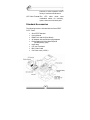
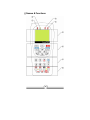
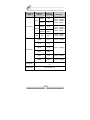
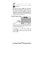
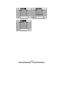
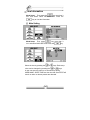
SecuriTEST User’s Manual
Table of Contents
Before Using SecuriTEST................................... 2
SecuriTEST Safety Precautions ........................ 3
Battery Charging Precautions ............................ 5
Standard Accessories.......................................... 8
Names & Functions.............................................. 9
General Specifications ...................................... 14
Meter Specifications .......................................... 15
Digital Multi-Meter .............................................. 23
PTZ Controller..................................................... 30
UTP Cable Tester............................................... 36
View Information................................................. 38
Before Using SecuriTEST
WARNING
Read the “Safety Information” portion of the manual
before using the SecuriTEST CCTV tester.
This manual is for users of the IDEAL SecuriTEST multifunction CCTV tester. The manual describes the
operation and function of the various features of
SecuriTEST.
It is highly recommended that operators read the entire
manual before using SecuriTEST to prevent damage to
the tester or injury to the operator.
2
WARNING
SecuriTEST Safety Precautions
When using the Digital MultiMeter function to measure
voltage or current, be sure that the input does not
exceed the capabilities of the tester. Overloading the
tester can cause damage or personal injury.
When measuring current of unknown values, always
begin with the 10A mode, then step down to the 400mA
input if necessary.
Environmental Limitations
Temperature:
-10 to 50 degrees C
14 to 122 degrees F
Relative Humidity:
0-90%, non-condensing
DC input voltage:
12V +/-10%, 1A
3
1. SAFETY INFORMATION
Do not use the unit in damp conditions or environments
where explosive gases may be present.
Do not handle the unit with wet hands.
Avoid dropping or causing mechanical shock to the unit.
Do not expose the ports to liquids and avoid exposure to
dust.
Use only specified replacement fuses.
Do not use damaged test leads with the DMM.
Do not measure resistance on powered circuits.
When using the DMM function, set the proper mode
before connecting to the circuit under test.
When measuring resistance, make certain that the circuit
is de-energized before connecting the test leads to the
circuit.
4
1. SAFETY INFORMATION
WARNING
Battery Charging Precautions
SecuriTEST is capable of
recharging NiMH batteries
installed in its battery
compartment.
To charge the batteries attach
the included 12V adapter to the
handset and set the main
power switch to the ON
position. Charging time takes 8
hours. Although the charge
LED will light regardless of the
position of the power switch,
charging will only occur with the
switch in the ON position.
Operation time is approximately
3-4 hours on a fully charged set
of batteries.
When using alkaline batteries
the
tester
can
run
for
approximately 2 hours on a new
set of batteries.
When using alkaline batteries,
set the switch inside the battery
compartment to OFF to prevent
accidental charging of alkaline
batteries.
5
- Battery Precautions The following batteries can be used with SecuriTEST:
> AA size alkaline batteries
> AA size rechargeable nickel metal hydrogen
(Ni-MH) batteries
When charging batteries in SecuriTEST:
Place both the MAIN POWER and the CHARGE
SWITCH to the “ON” position. The charge LED will light
when the MAIN POWER SWITCH is in either position,
but the batteries will charge only when the switch is set
to “ON”.
The CHARGE SWITCH is located on the upper part of
battery compartment. (Refer to the figure below)
The performance of batteries can be very different,
depending on manufacturers. Please use any reputable
brand for best performance. Do not mix batteries of
different manufacturers when charging batteries. Make
sure not to reverse the polarization of the batteries. Do
not short-circuit or disassemble batteries. Make sure to
check the polarization, voltage and current ratings before
charging batteries. Immediately disconnect the charger
should an abnormal situation arise.
6
FEATURES
SecuriTEST is a portable device for testing and
troubleshooting various functions of CCTV cameras. It
includes functions to test video image quality, control
PTZ operation, analyzes various PTZ protocols,
generates video test patterns, test UTP cables and
includes a full-function Digital MultiMeter.
All functions are controlled through the front keypad and
on-screen display for quick and easy setup of fixed and
PTZ camera systems.
2. SecuriTEST Introduction
Video Tester
►Displays the output signal from the
connected CCTV camera. Used to
adjust aim and adjust and
troubleshoot cameras.
►Video signal generator mode:
Outputs color bars and Red, Blue
and Green screens to allow
technicians to configure monitors
and troubleshot cameras by sending
a known good video signal down a
questionable coax run. Supports
both PAL & NTSC video signal
formats.
MultiMeter
►Measures
resistance,
AC/DC
voltage and current, and provides
continuity beep and display hold
functions.
PTZ Controller
►The PTZ controller tests the
movement of the dome and allows
manual zoom and manual focus
control of the camera. Supports
various
RS-485
and RS-422
7
protocols to allow operation with a
variety of camera manufacturers.
UPT Cable Tester ►The UTP cable check tests
unshielded cables for continuity,
opens, shorts and mis-wired pairs.
Standard Accessories
The following items are included with the SecuriTEST
CCTV Tester.
•
•
•
•
•
•
•
•
•
SecuriTEST Handset
User’s Manual
DMM Test Lead Set (Red, Black)
AC Adapter with international plug adapters
Rechargeable AA Nickel Metal Hydride
(Ni-MH) Battery (6ea)
Neck Strap
UTP test Terminator
BNC Video Cable
Car Power Jack (12VDC)
8
Names & Functions
9
Part
Name
Function
Power LED
Red LED is on when the system is
switched on
Charge LED
Green LED is on when AC adapter
connected
Data
Transmitting LED
Red LED is on when PTZ data is
transmitted
Data Receiving
LED
Red LED is on when PTZ data is
received
LCD
2.5” Color TFT LCD
Keypad
Main keypad for SecuriTEST
operation
MODE Button
SET Button
OSD Button
Mode Select: Video, MultiMeter, PTZ
Control, UTP Test (press and hold to
display main menu)
Used to confirm selection in menu
screens. Press and hold to access
PTZ protocol menu
Press to toggle on-screen display on
or off. Press and hold to turn off
power.
FAR Button
Adjusts PTZ focus (far direction) &
Video Mode Brightness
NEAR Button
Adjust PTZ focus (near direction) &
Video Mode Brightness
TELE Button
Zoom PTZ (zoom in) &
Adjusts Video Mode Contrast
WIDE Button
Zoom PTZ (zoom out) &
Adjusts Video Mode Contrast
Direction Keys
Moves up, down, right, left for PTZ
& for menus
10
Part
Name
MultiMeter Keys
Function
Selects functions of Digital MultiMeter
Resistance
Button
Selects Resistance Mode
Voltage Button
Selects Voltage Mode
Setup Change
Button
Toggles AC/DC Mode &
Selects Continuity Test
Current
Measuring
Button 1
Current
Measuring
Button 2
Current
Measuring
Button 3
Selects Current (below 400mA) Mode
HOLD, HELP
Button
Locks Auto-Ranging Function.
Hold for HELP
Selects low Current (below 4mA)
Mode
Selects Current (up to 10A) Mode
Ports for Digital MultiMeter
Test Lead Connection
Voltage & Resistance Port
Common Port
Current Measurement below 400mA
Port
Current Measurement up to 10A Port
11
PART
NAME
FUNCTION
Input BNC
Connect to camera output to display
image on screen
Output BNC
Use as pass-through port for camera
image or to output video test signal to
external monitor
Communication
Port
Input & Output of PTZ
communications signals
Kickstand
Holds unit upright when extended
Neck-strap Hook Connect neck-strap here to hang unit
Neck-strap Hook
Can be used to hang the unit upside
down
12
PART
NAME
FUNCTION
UTP Jack
Test jack for UTP Cable w/ RJ45 plug
AUX Jack
Audio, AUX Input Port
(for future use)
DC Power Jack
DC Power Input Jack
(DC12V, 1A)
Power Switch
Main Power Supply ON/OFF switch
13
3. SECURITEST SPECIFICATIONS
General Specifications
Electric
Characteristics
Input Voltage
12V ± 10% above 1A
Battery
Rechargeable Ni-MH battery
6ea (AAsize)
Built-in Charger
Charging
Time
Above 8 hrs
Operation
Time
> 3 hrs
TV Type
NTSC / PAL
Image Level
1 Vpp, 140IRE
Protocol
Multi-Protocol support
Transmission
Speed
2400bps ~ 38400bps
Transmission
Mode
RS-422, RS-485
Test
Direct / Cross Cable, and
Broken or Short-Circuit
Image
PTZ Operation
Test
UTP Cable
Test
Size
W 3.5” (88mm) X L 7.9” (190mm) X H 2.3”
(58mm)
14
3. SECURITEST SPECIFICATIONS
Meter Specifications
Measuring
Item
Measured
Value
Minimum
Measuring
Accuracy
400mV
100uV
± (0.8% + 2dgts)
4V
1mV
40V
10mV
400V
100mV
4V
1mV
40V
10mV
400V
100mV
DC Voltage
AC Voltage
400uA
± (1.0% + 2dgts)
4mA
2uA
40mA
20uA
400mA
200uA
10A
2mA
400mV
10A
± (1.2% + 3dgts)
(40Hz ~ 500Hz)
0.2uA
4mV
DC Current
± (1.0% + 2dgts)
± (1.5% + 2dgts)
15
± (2.0% + 3dgts)
Measuring
Item
Measured
Value
Minimum
Measuring
Accuracy
400uA
0.2uV
4mA
2uV
40mA
20uV
400mA
200uV
10A
2mV
± (3.0% + 4dgts)
40Hz ~ 500Hz
400 Ω
0.1 Ω
± (1.0% + 4dgts)
4k Ω
1Ω
40k Ω
10 Ω
400k Ω
100 Ω
4M Ω
1k Ω
± (2.0% + 4dgts)
40M Ω
10k Ω
± (3.0% + 5dgts)
4mV
AC Current
400mV
10A
± (1.5% + 5dgts)
(40Hz ~ 500Hz)
40Hz ~ 500Hz
± (1.8% + 5dgts)
(40Hz ~ 500Hz)
40Hz ~ 500Hz
± (1.0% + 2dgts)
Resistance
Continuity
Beeper is activated when the resistance is below 80
Ω
Rated Fuse
250 Volt 800 mA
16
4. FUNCTIONAL USE
Power ON/OFF
The power switch is located on the side of the
handset.
Turn the power switch on, and press
SecuriTEST.
to start
To turn off the system, press & hold
for more
than 3 sec. Then, POWER OFF is displayed on the
main screen with a beep. Release the button. Turn
the power switch OFF to prevent battery drain during
storage. The switch must remain ON to recharge the
batteries.
A rechargeable battery should be plugged in over 8
hrs to fully charge. The charged battery can operate
for about 3 hours.
When the battery indicator shows below [][], recharge
it for use. (Full charge: [][][][])
OSD Setup Screen When Power is ON
When power is turned on, the OSD is displayed, and it
automatically changes to the video test mode after 3-5
seconds.
The initial OSD displays the SecuriTEST version and the
initial setup on the screen.
Product Version:
2.02
Firmware Version: 2.03
Initital Protocol:
PELCO-D
TV Mode:
NTSC / PAL (automatic setup)
17
Battery Indicator: [][][][]
User Name:
User’s name (Name can be changed
in the Main menu)
Model & Software versions are subject to change without
notice.
Mode Setup
Pressing the
key changes the operation mode
between VIDEO, DMM, PTZ, and UTP.
To directly select a mode, press and hold the
key for 3 seconds then choose a mode and press the
key again to select the mode.
Video Tester Mode:
In this mode, the image quality of the external input
picture signal is tested. Unlike most monitors,
SecuriTEST does not have a video input amplifier,
thus picture quality problems caused by long cable
runs or poor connectors will be seen. The same signal
input into a standard external monitor may look fine
since the monitor will boost the signal to make the
image look clear. The un-amplified input circuit allows
users to troubleshoot cable and connector problems
that would normally go unnoticed. The VIDEO mode
also outputs color test patterns to aide in
troubleshooting or setting up monitors.
18
Digital MultiMeter Mode:
Use the MultiMeter mode to measure voltage, current
and resistance. In the resistance mode the continuity
beeper can be turned on to generate an audible tone
when the measured resistance is less than 80 ohms.
PTZ Controller Mode:
In this mode, the up, down, right, left movement for
PTZ cameras is controlled. Zoom and focus can also
be adjusted using the Tele/Wide and Far/Near buttons.
UTP Cable Test Mode:
UTP cables are tested for straight (direct), crossover,
opens, and shorts. The yellow UTP terminator must be
placed on the far end of the cable to make
measurements. Press the SET button to begin the
cable test.
The UTP test does not report the length of the cable.
View Information Mode:
In this mode, the basic information of SecuriTEST can
be seen (firmware version, battery level,
communications protocol and speed).
Main Setting Mode:
In this mode, the basic setup of SecuriTEST can be
changed (user’s name, auto power off time, beeper,
brightness, contrast, etc).
HELP:
HELP information relevant to the
current mode is displayed when
the key is pressed on for more
than 2 seconds.
This function gives a brief
explanation of the current
function.
19
VIDEO TEST
Connect the output of video output system to the video
input BNC of SecuriTEST.
Connect the video output BNC of SecuriTEST to the
video input terminal of the CCTV system. The image that
is displayed on SecuriTEST is passed through to the
external monitor.
OSD Screen Setup
VIDEO:
mode.
Indicates that the system is in the video test
20
NTSC:
Indicates if input or output video signal
system is NTSC or PAL. Input video signal
is displayed on LCD screen automatically.
Output video signal in Pattern Generator
mode can be switched to NTSC or PAL,
using the
B [][][][]:
or
keys.
Indicates screen brightness. The brightness
of the SecuriTEST LCD increases gradually
by +1 when
key is pressed, and
decreases gradually by -1 when the
key is pressed. Returns to the initial setup
value when one of the two keys is pressed
for more than 3 sec. Changes to brightness
do not effect the image sent through
SecuriTEST’s Video OUT port.
C [][][][]:
Indicates screen contrast, and the contrast
increases gradually by +1 when
key is
pressed, and decreases gradually by -1
key is pressed. Returns to the
when
initial setup value when one of the two keys
is pressed for more than 3 sec. Changes to
contrast do not effect the image sent
through SecuriTEST’s Video OUT port.
21
Pattern Generation Mode
To enter the PATTERN GENERATION MODE press the
key while in the VIDEO mode.
Output is changed between NTSC or
or
keys.
PAL, using
Output patterns can be cycled between
COLOR BAR, RED, BLUE, GREEN
using
COLOR
BAR
Press
or
RED
keys.
BLUE
key to return to Video MODE.
22
GREEN
Digital Multi-Meter
Voltage, Current,
measured.
Resistance,
continuity
can
be
WARNING
To prevent an electric shock, injury or damage to
SecuriTEST, turn off the power supply of the circuit and
discharge all the high-voltage capacitors before testing
resistance and continuity.
When using the meter function of your SecuriTEST,
make sure to turn on its power and set the proper mode
before connecting the test leads to the circuit to be
tested.
Key Selections
Press the
button, and then press
button to
change to continuity mode (continuity beeper on).
Press the
button, and then press
cycle between ACV/DCV.
button to
This button is used to test Current below 4mA.
This button is used to test Current below
400mA.
This button is used to test Current below
10A.This input is not fused. Be careful not to
measure across a live circuit (as when making
a voltage measurement) when the probe is
connected to the 10A input. Doing so will
create a short circuit and damage the meter.
23
Description of Meter Mode LCD Window
PART
FUNCTION
Test Mode
Test Value
DESCRIPTION
- Resistance test
- Continuity test
- Set-up tests of DC/AC voltage,
current
- Ω unit of resistance test is indicated
- Indicator of AC or DC value of
voltage or current
- AC voltage & current are indicated
as RMS (root mean square)
Measured Value
Graph
- Input measured value is indicated
in the form of a bar graph relative
to the maximum input level of the
selected mode
-
Measured Value
in Memory Hold
The measured value is stored and
indicated here when SET key is
pressed while taking measurements
MODE Display
Digital MultiMeter Mode is displayed
24
PART
FUNCTION
DESCRIPTION
DC
DC Voltage test
AC
AC Voltage test
OHM
VOLT
AMP
Resistance test
(Measuring unit: Ω)
Voltage test
(Measuring unit: V)
Current test
(Measuring unit: mA, A)
Continuity test
(Beeps below 80 Ω)
Measuring Resistance
The unit of measurement is Ω. The meter sends low
current into the circuit to measure its resistance.
How to measure: Connect the
red lead to
and the black
lead to
as shown in the
figure to the left. Measure in
the resistance mode by
pressing
25
on the keypad.
Testing Continuity
Continuity indicates the presence of a complete path for
current flow. The continuity test features a beeper that
sounds when a circuit is complete. The beep allows
users to quickly test continuity without having to watch
the display.
How to test: The resistance mode changes to the
continuity mode, when
is pressed. The beeper is
activated when the resistance between the red probe
and black probe is below 80Ω.
26
Measuring AC & DC Voltage
Voltage means the difference in electrical potential
between two points. The polarity of AC voltage varies
over time, while the polarity of DC is constant over time.
The meter displays AC voltage value as RMS (root
mean square) readings. The RMS value means the
equivalent dc voltage that can produce the same amount
of heat in a resistance as the measured sinewave
voltage.
How to measure: First, press
, the voltage
measuring button, then selects AC or DC by
pressing
. When measuring DC, place the red lead
on the “+” point, and the black lead on “-” point of the
circuit.
27
Measuring AC & DC Current
Current is simply defined as a flow of electrons running
through a conductor. To measure current, you must
break the circuit under test, and place the meter in series
with the circuit. The current measuring range of the
meter is 10A max.
How to measure: First, turn off the power to the circuit
and discharge any high voltage capacitors. Place the red
lead into the mA or 10A terminals in accordance with the
value to be measured. Select one of the buttons
or
When
mA. When
10A.
,
.
&
are selected, place the red lead on
button is selected, place the red lead on
28
WARNING
Check the position of the test lead set in current test
mode. Place the red lead at mA only when below
400mA, and place it at 10A when the value to be tested
is over 400mA, or the value is unknown.
WARNING
Do not attempt to measure voltage when the test leads
are connected to the mA or 10A port. Doing so will
create a short circuit condition and blow the internal fuse
or cause damage to the instrument and possibly cause
bodily injury.
29
PTZ Controller
Connecting Camera and Monitor
PTZ Operation Test: Up, Down, Left, Right, Zoom and
Manual focus control are possible. The tester can also
be set to various protocols and transmission speeds
(baud rates).
- PTZ Control Setup Screen
Press and hold the SET button for 3 seconds until PTZ
protocol menu activates.
Address Setup
Screen
Protocol Setup
Screen
30
Communications
Speed Setup
Screen
- Keyboard Control Code Screen
- The control
commands from the
keyboard of an external
control are displayed on
the screen. Most
important is that the
communications speed
be matched.
When you want to know the input signal of an exterior
controller, you can see the input data by connecting the
communications cable to the RX terminal of the
SecuriTEST.
Using the PTZ Controls
PT control (Up, Down, Left, Right), is performed using
the arrow keys.
Zoom is controlled using the
TELE/WIDE buttons, and focus is controlled with the
FAR/NEAR buttons.
PTZ Function Setup
Press the
key then use the arrow keys to
select GPST / SPST / TOUR / and SPD functions. Press
to activate a function
GPST: Short for GO TO PRESET - Moves the
camera view to the designated preset location.
SecuriTEST can address up to 99 stored
positions in the camera. The camera goes to
the GPST position after the
key is
pressed. Select the previously memorized
PRESET number using the arrow keys. When
the desired number is displayed, press
31
to move the camera to the stored
position.
SPST: Short for SET PRESET - Memorizes
PRESET. Setup can range from 1 up to 99.
First, move the camera to the desired
position. Press the
key to activate
&
keys,
the menu, then using the
select SPST and set the address to store
using the
&
keys. Press the
key once more to save the
address. This function saves the current
camera position into the cameras internal
memory. This set position can be recalled
from SecuriTEST or any other PTZ
controller at a later time.
TOUR: Operates TOUR through SPST points. Can
be programmed from 1 to 99. TOUR is set
using the same process described for the
SPST function. To program the camera tour,
the camera must support programming via
the SecuriTEST interface. This is accessed
by using the MENU function on the
SecuriTEST PTZ screen. If the camera
already has tours programmed, use the
TOUR mode to recall and activate a tour
that was previously saved in the camera.
SPD:
Sets the speed of the camera. Programmed
using the same described for SPST. Range
is from 1 to 16. Always defaults to 15 when
cycling power or changing modes. High
speeds are preferred to test the cameras
operation while low speeds are used for
precise control when storing set points
(SPST).
32
MENU: Activates the PTZ camera’s internal menu.
Manu PTZ cameras have an on-screen
menu system that allows SecuriTEST to
program various functions of the camera
including day/night mode, focus settings,
and tours. When a tour is programmed into
the camera it can be activated with
SecuriTEST using the TOUR function in the
menu.
33
CAUTION
Make sure to check communications protocol,
transmission speed, and ID.
PTZ Control Setup
PTZ ADDR is activated on the upper part of the LCD
screen, when
key is held for more than 3
seconds. The menu also controls the PTZ Protocol and
Baud rate.
Use the
&
keys to move between the menus.
PTZ ADDR: Select the address of the PTZ Camera.
Each PTZ camera in a system must have a unique
address from 1 to 255 to allow it to be operated by a
PTZ controller. Use the PTZ ADDR function to set the
address of the camera to control.
34
PROTOCOL: Choose PTZ PROTOCOL
Camera manufacturer use various communications
protocols to control the PTZ functions of the camera.
Use the PROTOCOL menu to set the output of
SecuriTEST to match the protocol of the camera system
in use.
* BAUDRATE: Select TRANSMISSION SPEED
The initial setup is 2.4kbps, it can be set
from 2.4kbps to 38.4kbps.
To escape from the PTZ CONTROL SETUP mode,
press the
key again.
35
CAUTION
Make sure to check CAMERA ID, PROTOCOL,
BAUDRATE when testing. PTZ operation can not be
done when the setup is different from the camera. If you
are unsure of the cameras configuration, connect the
camera to the Video IN of SecuriTEST then cycle the
cameras power. Often the camera will display its PTZ
configuration during the boot process allowing the tester
to be set to a matching configuration.
UTP Cable Tester
Connect one end of the UTP cable to be tested to the
UTP Cable Test port of SecuriTEST and the other end to
the yellow UTP Cable terminator.
The
condition
of
the
cable
can
be
tested
by
pressing
. The test can detect straight and
crossover cables as well as shorts, opens and most
miswire conditions.
36
Crossover Cable
Short-circuit & Disconnection
Direct Cable
37
View Information
Mode Setup: First, press the
key more than 3
sec. and select VIEW INFORMATION. Press the
key to view the information.
Main Setting
Mode Setup:
First, press
key more than 3
sec. and select MAIN SETTING. Press the
Select the item by pressing the
&
key.
keys. Each setup
value can be changed by pressing the
&
keys.
A user can enter the name he or she wants by editing
USER NAME. SLEEP TIME sets the time that SecuriTEST will
remain on when no button presses are detected.
38
IDEAL Industries, INC.
Becker Place
Sycamore, IL 60178
Customer Service: 800-435-0705
www.idealindustries.com
www.idealindustries.co.uk
www.idealindustries.de
Printed in Korea
Rev 2.0 May 2007