1
i
SEAl, S
OWNERS
MANUAl.
MODEL
NO.
315.! 1713!
CAUTION:
Read Rules for
Safe Operation
and Instructions
Carefully
£
3
SANDER
DOUBLE INSULATED
SAVE THIS
MANUAL
FOR
FUTURE REFERENCE
Warranty
Introduction
Operation
Maintenance
Repair Parts
Designed exclusively for and sold only by
SEARS, ROEBUCK AND CO,, Sears Tower, Chicago, lL 60684
6_2_47 525
1 _J0
PRINTED
IN U S A
FULL ONE YEAR WARRANTY ON CRAFTSMAN BELTSANDER
If this Craftsman Belt Sander faits to give complete satisfaction wtthin one year from the date of purchase RETURN1TTO THE NEARESTSEARS SERVICECENTER/DEPARTMENT THROUGHOUTTHE
UNITED STATESand Sears will repair it, free of charge
tf this bett sander is used for commercial or rental purposes this warranty applies for only 90 days from
the date of purchase
This warranty gives you specific
legal rights, and you may also have other rights which vary from state
to state
SEARS, ROEBUCKAND CO,
DEPT 731CR-W
SEARS TOWER
CHICAGO, IL 60684
INTRODUCTION
GENERAL
Your Craftsman 3-lnch Belt Sander is suitable for
coarse, medium and fine sanding of wood, metals,
plastics and other materials it is ideal when used for
smoothing
rough boards, chamfering, rounding
edges and many other general sanding applications
Its balanced design makes it easy to use.
IMPORTANT -- Servicing of a tool with double Insulation requires extreme care and knowledge of the
system and should be performed only by a qualified
service technician. For service, return the tool to
your nearest Sears store for repair which wilt be
done with original factory replacement parts.
DOUBLE INSULATION
Double insulation is a concept in safety, in electric
power tools, which eliminates the need for the usual
three wire grounded power cord and grounded supply system Wherever there ts electric current _n the
too! there are two complete sets of insulation to protect the user Alt exposed metal parts are isolated
from the tnternat metal motor components with pro..
tecttng insulation.
RULES FOR SAFE OPERATION
READ ALL INSTRUCTIONS
1 KNOW YOUR POWER TOOL -- Read owner's manual carefully
Learn its applications and limitations
as well as the specific potential hazards related to
this toot
2 GUARD AGAINST ELECTRICAL SHOCK BY PREVENTING
BODY CONTACT
WITH GROUNDED SURFACES. For example: Pipes, radiators, ranges, refrigerator enclosures.
3 KEEP GUARDS IN PLACE and in working order.
4 KEEP WORK AREA CLEAN. Cluttered areas and benches invite accidents
5, AVOID DANGEROUS ENVIRONMENT.
Don't use power tool in damp or wet
locations or expose to rain. Keep work area well lit,
6 KEEP CHILDREN
AWAY. All visitors
should
wear safety-glasses
and
be kept a safe distance
from work area_ Do not let visitors
contact tool or
extension cord.
7, STORE IDLE TOOLS. When not in use, tools should be stored in a dry, high or
locked-up place -- out of the reach of children_
8, DON'T FORCE TOOL. It wilt do the job better and safer at the rate for which it
was designed.
9_ USE RIGHT TOOL. Don't force small toot or attachment to do the job of a heavy
duty toot_ Don't use tool for purpose not intended - for example - Don't use
a circular saw for cutting tree limbs or logs,
Page
2
RULESFORSAFEOPERATION
(Continued)
1OrWEAR PROPER APPAREL, NO loose clothing
11.
12
13
14
15
16
17
18
19
20
21
22
23
24
25
26
27
28
29
30
31.
32
or jewelry to get caught in moving
parts.. Rubber gloves and non-skid footwear are recommended
when working
outdoors, Also, wear protective hair covering to contain long hair.
USE SAFETY GLASSES with all tools Also face or dust mask if sanding operation is dusty
DON'T ABUSE CORD. Never carry tool by cord or yank it to disconnect
from
receptacle. Keep cord from heat, oil, and sharp edges.
SECURE WORK. Use clamps or a vise to hold work It's safer than using your
hand and it frees both hands to operate tool
DON'T OVERREACH,. Keep proper footing and balance at all times Do not use
on a ladder or unstable support.
MAINTAIN TOOLS WITH CARE. Keep tools sharp at all times, and clean for best
and safest performance
Follow instructions
for lubricating
and changing accessories
DISCONNECT TOOLS. When not in use, before servicing, or when changing attachments, blades, bits, cutters, etc, all tools should be disconnected
REMOVE ADJUSTING KEYS AND WRENCHES° Form habit of checking to see
that keys and adjusting wrenches are removed from tool before turning it on
AVOID ACCIDENTAL
Si"ARTINGo Don't carry plugged-in tools with finger on
switch. Be sure switch is off when plugging in.
OUTDOOR USE EXTENSION CORDS. When tool is used outdoors, use only
extension cords suitable for use outdoors Outdoor approved cords are marked
with the suffix W-A, for example -- SJTW-A or SJOW-A.
NEVER USE THIS OR ANY POWER SANDER FOR WET SANDING. Failure to
comply can result in electrical shock causing serious injury or worse.
KEEP HANDS AND FINGERS AWAY FROM SANDING AREA AND MOVING
SANDING BELT.
NEVER USE IN AN EXPLOSIVE ATMOSPHERE. Normal sparking of the motor
could ignite fumes.
INSPECT TOOL CORDS PERIODICALLY and if damaged, have repaired at your
nearest Sears Repair Center. Stay constantly aware of cord location
INSPECT EXTENSION CORDS PERIODICALLY and replace if damaged.
KEEP HANDLES DRY, CLEAN, AND FREE FROM OIL AND GREASE. Always
use a clean cloth when cleaning
Never use brake fluids, gasoline, petroleumbased products, or any strong solvents to clean your tool.
STAY ALERT. Watch what you are doing and use common sense Do not operate tool when you are tired. Do not rush
CHECK DAMAGED PARTS. Before further use of the tool, a guard or other part
that is damaged should be carefully checked to determine that it wilt operate
properly and perform its intended function. Check for alignment
of moving
parts, binding of moving parts, breakage of parts, mounting, and any other conditions that may affect its operation
A guard or other part that is damged
should be properly repaired or replaced by an authorized service center.
DO NOT USE TOOL IF SWITCH DOES NOT TURN IT ON AND OFF. Have defective switches replaced by an authorized service center.
Inspect for and remove all nails from lumber before sanding
DRUGS, ALCOHOL, MEDICATION.. Do not operate tool while under the influence of drugs, alcohol, or any medication
WEAR HEARING PROTECTION DURING EXTENDED PERIODS OF OPERATION°
SAVE THESE INSTRUCTIONS_
Refer to them frequently
and use them to
instruct third party users If you loan someone your Sander, loan them these
instructions
also
Page 3
OPERATION
Make sure power supply
only.
is 110-120
Before attempting
to use
yourself
with all operating
and safety requirements.
REAR
TRACKING
HAN DLE'-..._,..
SCREW
volts, 60 HZ, AC
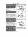
HANDLE
your Sander, familiarize
features
(See Figure
1)
_,,IG Fig
PULLEY
1
BELT
LOCK "ON"
BUTTON
SWITCH
The switch
of your sander is equipped
with a "lockon" feature which is convenient
when sanding
for
extended periods of time, To lock-on, simply depress
the trigger
of the switch,
push in the lock button
located on the side of the handle, then while holding
the lock button
pushed in, release the trigger
See
Figure 2 To release the lock, depress the trigger and
release it If you have the "Lock-On"
feature engaged
during use and your Sander becomes
disconnected
from power supply, disengage
the "Lock-On"
feature
immediatel,
CORRECT
Fig
2
PREPARING
FOR OPERATION
For ease of operation
and maintaining
proper con..
trot, your Sander has a front handle and a rear han
die These handles allow two-hand
operation
which
aid in maintaining
controi,
keeping
sanding
area
level with workpiece,
and keeping
hands clear of
sanding
belt. When operating
your Sander always
hold the front handle with your left hand and the rear
handle with your right hand as shown in Fig. 2.
KEEP HANDS AND FINGERS
AWAY FROM THESE AREAS AT ALL TIMES
See
Fig
3
Fig, 3
Always
operate
your
Sander
as shown
in Fig
2,,
Page 4
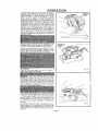
OPERATION
Selecting the correct size and type sanding beit is an
important step in achieving a high quality sanded
finish. Standard 3 inch x 21 inch sanding belts made
' of alumt'num oxide, silicone carbide, and other synthetic abrasives are best for power sanding, in
general, coarse grit will remove the most material
and fine grit wilt produce the smoothest fintsh in alt
sanding operations. The condition of the surface to
be sanded wtlt determine which grit belt will do the
job, if the surface is rough, start with a coarse grit
belt sanding until surface is uniform Medium grit
belt may then be used to remove scratches left by
the coarser belt and fine grit belt used for finishing
of the surface. Always continue sanding with each
grit belt until the surface is uniform
LIFT TENSION RELEASE LEVER TO REMOVE
SANDING BELT
Fig 4
INSTALLING
AND ADJUSTING SANDING BELT
DISCONNECT SANDER FROM POWER SUPPLY
WHILE ASSEMBLING
PARTS OR MAKING AD.
JUSTMENTS,
To release the sanding belt, lift tenslon release lever
straight up as shown in f_gure 4. When sufficient
force is exerted, the spring wilt be compressed
allowing the pulley to lock in a rear position This
frees the sanding belt so It can be removed. Instalt
new belt making sure arrow inside of belt is pointing
in the direction of rotation, which is cfockwise when
looking into open side of sander See Fig 5. Roughly
align the belt to its correct position, then release tension on pulley Release tension by lowering tension
release _ever as shown in Figure 6 The pulley will
snap back into operating position
Fig
SANDING
5
BELT
LOWER TENSION RELEASE LEVER TO SECURE
SANDING BELT
Fig 6
1,1.1
Page 5
OPERATgON
ALWAYS
WEAR SAFETY
GOGGLES
OR SAFETY
GLASSES WiTH SIDE SHIELDS WHEN OPERATING
YOUR SANDER
To adust
sanding
belt, connect
Sander to power
supply
Place Sander
in upside
down position
as shown
in Figure 7, NOTE: This
position
is for adjustments
only. The Sander ts not in
an operating
position
Putl switch trtgger and release
immediately.
Observe tracking
of sanding belt If the
sanding
belt runs inward, turn the tracking
screw
clockwise
If the sanding belt runs outward, turn the
tracking
screw
counterclockwise.
This should
be
done until you are sure belt will not run off sander, or
come in contact with internal parts After installing
a
new sanding
belt, tt may become
necessary
to
change the adjustment
several times until the bett
becomes
)liable.
..........
'........
SAN DING
BELT
Fig
When you are sure the belt will not rub against internal parts start your Sander and fine adjust the tracking screw until the belt stab
zes See Figure 8
7
TRACKING
SCREW
When correctly
adjusted,
the outer edge of the belt
wilt be even with the outer edge of the base of your
Sander. #ell life wilt be greatly increased
if a few
seconds
are spent adjusting
the belt tracking.
TO OPERATE
Clamp or otherwise
from moving under
secure
the
your Sander.
work
to prevent
Fig. 8
it
Before placing Sander on work surfac
squeeze the trigger switch
and let the motor reach
its maximum
speed, then toweryour
Sander to the
work surface with a slight forwardmotion
Using the
rear handle to control your Sander and the front handle only to guide it, move it slowly over the work See
Fig 9. Allowing
your Sander to remain in one place
will result in an uneven surface.
Your sander
was designed
to provide
the proper
weight on the sanding belt Extra pressure wilt result
in uneven work, clogged
belts, and possible
motor
burnout.
NOTE: The front roller of your sander was
not designed
for contour
sanding
Sanding
on lhe
front ro!ler could cause irregularity
in sanding
belt
tracking
Fig
Use a coarser belt when heavy cutting
is desired, not
heavy pressure
The importance
of this cannot be
over-emphasized
The weight has been built into the
tool to give the most efficient
pressure
at the proper
location
Page 6
9
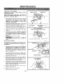
MAINTENANCE
TIMING
BELT
REPLACEMENT
DISCONNECT
SANDER
BEFORE SERVICING
FROM
POWER
SUPPLY
SMALL
TIMING
PULLEY
BELT
WHEN
REPLACING
TIMING
BELT. USE REPLACE,
MENT BELT NUMBER
989368.,000 ONLY
See Key
Number 5 on Parts Mst, Page 11
1
2
3
Remove sanding belt from sander
See installing
and adjusting
sanding
belt,
Page 5. NOTE:
REMOVING
THE
SANDING
BELT
WILL
SIMPLIFY
THE
PROCESS
OF
INSTALLING
YOUR NEW TIMING
BELT,
Remove the two belt cover screws, Then remove
the belt cover
See Key Numbers
! and 2 on exploded view and parts list, pages !0 and 11,
Force
old
be{t
from
small
puttey
with
a
screwdriver
and remove it from large pulley
If it
is worn out, simply cut the old belt and remove it
4
Install
Figure
5
Holding the belt as shown in Figure 1t, press the
belt onto the smelt pulley, NOTE: TO SIMPLIFY
THE PROCESS,
TURN THE LARGE PULLEY AS
YOU PRESS THE BELT ONTO
THE SMALL
PULLEY,
Reassemble
belt cover and screws
6
new
10
belt
_NEVER
YOUR
SANDER
PLACE
SWITCH
over
large
pulley
first
BELT
BELT COVER
SCREWS
COVER
==_ 10
APPLY PRESSURE
HERE AND TURN LARGE PULLEY
See
ATTEMPT
TO OPERATE
WITHOUT
BELT
COVER
tN
REPLACEMENT
DISCONNECT
THE SANDER
FROM POWER SUPP.
LY WHILE
REPLACING
PARTS OR MAKING
AD.,
JUSTMENTS,
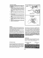
t
Remove the handle cover and screws. NOTETHE
LOCATIONS
OF ALL WIRING IN THE HANDLE
AND HOW EACH CONNECTION
IS MADE TO
THE SWITCH, Connections
and wiring
position
must
be identical
when
installing
the new
switch
See Figure I2
Lift the switch
away from
the handle,
then
release the leads to the switch
by inserting
a
!/32"
diameter
pin or nail into each switch
lead
receptacle
See Figure 13
3
Make the lead connections
to the new swilch
by
pushing
each lead as far as possible
into the
switch
lead receptacles
Pull on leads to check
lead connections
with lead receptacles
4
Arrange the wiring in the handle so that it will not
be pinched
or contact
screws when the handle
cover and screws are replaced,
then position
the
switch
in place: See Figure 12
5,,
Place the
locations
cord and bend
See Figure I2
6,
Replace
handle
7,
Tighten
all screws
cover
relief
in their
correct
and screws
securely
Page
BEND
RELIEF
SCREWS
HANDLE_OVER
Fig 12
1/32" DIAMETER
NAIL OR PIN
CORD REPLACEMENT
DISCONNECT THE SANDER FROM POWER SUPPLY WHILE REPLACING PARTS OR MAKING ADJUSTMENTS.
1 Remove handle cover and screws as described
on Page 7, Note the locations of all wiring in the
handle end how each connection is made to the
cord, Connections and wid.ng position must be
identical when installing the new cord See
Figure 14.,
2 Remove the switch from the handle and disconnect the cord reads lrom the switch, See Figure
15
3 Remove the bend relief from old cord and place it
on the new one
4, Push each lead of the new cord as far as possible
into the proper sw_tch lead receptacles
Pull on
leads to check lead connections with lead receptacles
5 Arrange the widng in the handle so that it will not
be pinched when handle cover and screws are
replaced
Posttion the switch in place See
Figure 14_
6, Place the bend relief and cord in their correct
locations, then replace handle cover and screws
7 Tighten all screws securely,
GENERAL
Only the parts shown on parts list, page eleven, are
intended to be repa}red or replaced
by the customer
All other parts represent
an {mportant
part of the
double insulation
system and should be serviced only by a quatified
service technician
Avoid using solvents
when cleaning
plastic
parts.
Most plastics
are susceptible
to various
types of
commerciaI
solvents
and may be damaged
by their
use Use clean cieths
to remove dirt, carbon dust,
etc
BEND
RE
SCREWS
HANDLE
COVER
Fig
14
Fig,
15
1/32" DIAMETER
NAIL OR PIN
/
When electric
tools are used on fiberglass
boats,
sports cars, etc, it has been found that lhey are subiect to accelerated
wear and possible
premature
failure,
as the fiberglass
chips and grtndings
are
highly
abrasive
to bearings,
brushes
commutator,
etc, Consequently
it is not recommended
that this
tool be used for extended
work on any tiberglass
material
During any use on fiberglass
it is extremely
important
that the tool is cleaned frequently
by blowo
ing with an air jet ALWAYS
WEAR SAFETY GOGGLES, SAFETY GLASSES WITH SIDE SHIELDS, OR
A DUST MASK DURING POWER TOOL OPERATtON
OR WHEN BLOWING DUST,,
LUBRICATION
All the bearings in this tool are lubricated with a suf.
ficient amounl of high grade lubricant
for the life of
the
unit
under
normal
operating
conditions,
therefore,
no further lubrication
is required
EXTENSION
CORDS
The use of any extension
cord witl cause some loss
of power To keep the loss to a minimum
and to pro.
vent too! overheating,
follow the recommended
cord
sizes on the chart at right
When too_ ',s used out,,
doors, use only extension
cords suitable
for outdoor
use and so marked
Extension
cords are available at
Sears Catalog Order or Retail Stores
Extension Cord Length
25.,50Ft
50,100 Ft
Page 8
Wire Size A,W.G
16
14
I
THE FOLLOWING RECOMMENDED ACCESSORIES ARE CURRENT AND .......
WERE AVAILABLE AT THE TIME THIS MANUAL WAS PRINTED.
CORD LOCK
Cat, No,.-9 2595
CARRYING CASE
Cat. NOo 9 14703
I
CRRF'r_MRN
CLOTH BACKED SANDING BELTS
Cat, No, 9 22304-X..Fine
Cat, NOo 9 22301.Fine
Cat° No. _9 22302-Medium
Cat, No. 9 22303-Coarse
cat° No, 9_ 22305-X,Coarse
POLYESTER BACKED SANDING BELTS
Cat. No. _9 23201,X, Fine
Cat° No, 9 23202-Fine
Cat, Noo -9 23203oMedlum
Cat, No, 9 23204-Coarse
Dustless Sanding Attachment 9 11766
The use of attachments or accessories not listed above might be hazardous°
i
i
i i
The operation of any Sander can result in foreign objects being thrown into your
eyes, which can result in severe eye damage, Before commencing power tool
operation, always wear safety goggles or safety glasses with side shields and a full
face shield when needed. We recommend wide vision safety mask for use over
spectacles or standard safety glasses with side shields, available at Sears Catalog
Order or Retail Stores°
NOTES
Page 9
CRAFTSMAN
3 INCH BELT SANDER
-- MODEL NUMBER
315.117131--
2
11
SEE NOTE 'W" PAGE 11
15
12
13
17
32
3O
42
35
34
31
For Parts
ill
List --
See Page 11
;
Page 10
CRA[
AN 3 INCH BELT SANDER
-- MODEL NUMBER
315.117131
i
!
mention
the Model Number
in all correspondence
regarding
your CRAFTSMAN
SANDER
or
I The
Number
be found on a plate attached
to the End Cap ot your Sander. Always
I
when Model
ordering
repair wil_
parts.
SEE BACK PAGE FOR PARTS ORDERING
INSTRUCTIONS
i ii
KEY
NO.
PART
NUMBER
1 610122-003
2 998367-001
3 607776-002
4 726693-020
5 989368-000
6 "998366-004
7 703493-809
8 998423-002
9 725693-004
t0
989366-000
11 99837_001
12 999448-003
13 607461-002
t4
516103-802
15 998373-002
16 999954-002
17 999945-004
18 999927-001
19 622347.001
20 999923-001
21 998370-00t
22 99837!-001
23 998376-002
24 612665-005
DESCRIPTION
PARTS
LIST
QUAN.
KEY
NO,
PART
NUMBER
998378-001
"Screw (#8-32 x 3/8" Pan Hd, T.C,) ...........
Belt Cover ...............................
Driven
Pulley ............................
4
1
!
25
26
27
•Screw (#8-32 x 3/8'" Fit. Hd.) ...............
Timing Belt ..............................
Gear Housing Cover w/Bearing
.............
Washer .................................
3
1
1
2
28
29
30
31
Pinion ..................................
*Screw (#8-32 x 7/8" Fii. HdJ ................
Pulley .................................
I
1
1
32
33
34
Tracking
Knob ..........................
Wear
Strip ..............................
1
1
35
36
Retaining
Ring ...........................
Thrust Washer ...........................
2
1
37
38
idler Roller W/Bearings
...................
Idler Rotter Shaft .........................
Yoke Assembly
W/Spring
.................
1
1
1
39
40
41
Release Lever Assembly
Washer ................................
1
!
42
44
*Screw (#10-32 x 1/2" Pan Hd,) ..............
Bushing
................................
Torsion
Spring ...........................
Platen .................................
1
2
1
1
45
"Screw
2
(#10-32 x 1/2"
i.l,llp
..................
Pan Hd. T.F.) ..........
46
47
DESCRIPTION
998380-001
99811_001
999942-001
703774-003
98959_001
999932-001
817966-009
990493-006
999929-001
613651-001
998895-001
706239-845
998358-001
616247-001
Backing
Pad .............................
Sanding
Belt (3" x 21") ....................
Wear Plate ..............................
Data Plate ...............................
1
1
1
1
Drive
Steel
1
1
Roller Assembly
....................
Bait ...............................
*Screw (#8-10 x 1-1/8"
Fif. Hd.) ..............
End Cap ................................
*Screw (#8-10 x 5/8" Pan Hd.) ...............
Cord ....................................
Handle Cover ............................
Bend
Retiet .............................
Switch ..................................
931744-818
999463-001
622347,003
705239-847
612547-525
1
1
Spnng ..................................
Washer ................................
1
1
NOTE: "A" -- The assemblyshown represents an tmportanl part of the Double Insulated System.To avoid the possibility of alieratlon or damage to the system service should be performed
by your nearest Sears Repair Center. Contact your nearest
Oatalog Order or Retail Store.
,i.ii.Niii
i
i
i
i
i
*Standard Hardware Item i May Be Purchased Locally
"*Available From Div. 98 -- Source 980.00
•"*Sanding Belts m assorted grits {or both sanding wood and metal may be obtained from your nearest Sears Catalog Order or
Retail Store,
iiii
ii
i
Page t 1
, i ii
i
Jllll.
i
3
1
7
1
1
1
1
Thrust Washer ...........................
Gear ...................................
Logo Plate ..............................
Glamor
Plate ............................
*Screw (#10-32 x 7/8" Pan Hd. T.F.)
(For use with Key No. 44 only) ............
Spring Washer ...........................
Washer .................................
Owner's
Manual
967878-003
612665.006
QUAN.
i
i i
2
1
2
1
1
!
C
3 raNCH
ELT SANDER
OWNERS
MANUAL
DOUBLE iNSULATED
SERVICE
Now that you have purchased
your Belt Sander,
should a need ever exist for repair parts or service,
simply contact any Sears Service Center and most
Sears, Roebuck and Co. stores Be sure to provide
all pertinent facts when you caII or visiL
MODEL NO.
315.117131
The model number of your Belt Sander will be found
on the plate located on the side of your sander
HOW TO ORDER
REPAIR
WHEN ORDERING REPAIR PARTS, ALWAYS
THE FOLLOWING INFORMATION:
PARTS
• PART NUMBER
MODEL NUMBER
315.117131
GIVE
• PART DESCRIPTION
o NAME OF ITEM
3" Belt Sander
Alt parts listed may be ordered from any Sears Service Center and most Sears stores
.
If the parts you need are not stocked locally, your
order will be electronically
transmitted
to a Sears
Repair Parts Distribution
Center for handling°
SEARS,
ROEBUCK
AND
CO,
Sears Tower,
Chicago,
IL 60684


![j:j_"Xt$l"j:]:":,lg]:"r/Human Resources have been duty - e](http://vs1.manualzilla.com/store/data/005657435_1-26d97049bf04f0fd92265d73e45a9ab3-150x150.png)