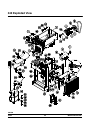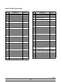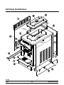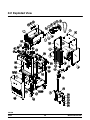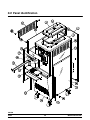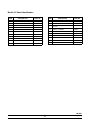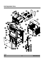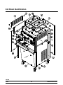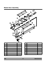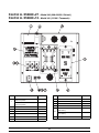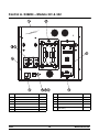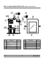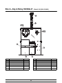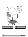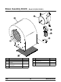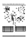
1
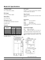
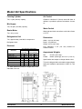
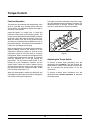
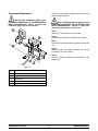
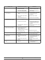
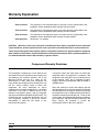
Models 340/341/342
Slush Freezers
Service Manual
028764- S
11/10/08
Table of Contents
Section 1: Introduction . . . . . . . . . . . . . . . . . . . . . . . . . . . . . . . . . . . . . . . . . . . . . . .
1
Safety . . . . . . . . . . . . . . . . . . . . . . . . . . . . . . . . . . . . . . . . . . . . . . . . . . . . . . . . . . . . .
2
Model 340 Specifications . . . . . . . . . . . . . . . . . . . . . . . . . . . . . . . . . . . . . . . . . . . . .
4
Model 341 Specifications . . . . . . . . . . . . . . . . . . . . . . . . . . . . . . . . . . . . . . . . . . . . .
5
Model 342 Specifications . . . . . . . . . . . . . . . . . . . . . . . . . . . . . . . . . . . . . . . . . . . . .
6
Running Specifications . . . . . . . . . . . . . . . . . . . . . . . . . . . . . . . . . . . . . . . . . . . . . . .
7
General Installation Instructions . . . . . . . . . . . . . . . . . . . . . . . . . . . . . . . . . . . . . . .
8
Environmental Notices . . . . . . . . . . . . . . . . . . . . . . . . . . . . . . . . . . . . . . . . . . . . . . .
11
Section 2: Systems and Controls . . . . . . . . . . . . . . . . . . . . . . . . . . . . . . . . . . . . . .
13
Refrigeration System . . . . . . . . . . . . . . . . . . . . . . . . . . . . . . . . . . . . . . . . . . . . . . . .
14
Torque Control . . . . . . . . . . . . . . . . . . . . . . . . . . . . . . . . . . . . . . . . . . . . . . . . . . . . . .
15
Section 3: Troubleshooting . . . . . . . . . . . . . . . . . . . . . . . . . . . . . . . . . . . . . . . . . . .
17
General Troubleshooting Guide . . . . . . . . . . . . . . . . . . . . . . . . . . . . . . . . . . . . . . .
18
Troubleshooting Torque Components . . . . . . . . . . . . . . . . . . . . . . . . . . . . . . . . . .
20
Section 4: Parts . . . . . . . . . . . . . . . . . . . . . . . . . . . . . . . . . . . . . . . . . . . . . . . . . . . . . .
21
Warranty Explanation . . . . . . . . . . . . . . . . . . . . . . . . . . . . . . . . . . . . . . . . . . . . . . . .
22
340 Exploded View . . . . . . . . . . . . . . . . . . . . . . . . . . . . . . . . . . . . . . . . . . . . . . . . . .
24
340 Panel Identification . . . . . . . . . . . . . . . . . . . . . . . . . . . . . . . . . . . . . . . . . . . . . .
26
341 Exploded View . . . . . . . . . . . . . . . . . . . . . . . . . . . . . . . . . . . . . . . . . . . . . . . . . .
28
341 Panel Identification . . . . . . . . . . . . . . . . . . . . . . . . . . . . . . . . . . . . . . . . . . . . . .
30
Table of Contents
Models 340/341/342
Table of Contents -- Page 2
342 Exploded View . . . . . . . . . . . . . . . . . . . . . . . . . . . . . . . . . . . . . . . . . . . . . . . . . .
32
342 Panel Identification . . . . . . . . . . . . . . . . . . . . . . . . . . . . . . . . . . . . . . . . . . . . . .
34
Beater Door Assembly . . . . . . . . . . . . . . . . . . . . . . . . . . . . . . . . . . . . . . . . . . . . . . .
36
Control A. X52469--27 -- Model 340 (208--230/60/1 Bristol)
Control A. X52469--12 -- Model 340 (115/60/1 Tecumseh) . . . . . . . . . . . . . . . .
37
Control A. X49284 -- Models 341 & 342 . . . . . . . . . . . . . . . . . . . . . . . . . . . . . . . .
38
Control A. X49284SP -- Model 342 (Left Side) . . . . . . . . . . . . . . . . . . . . . . . . . .
39
Box A.--Cap & Relay X48892--27E -- Model 340 (208--230/60/1 Bristol) . . . . .
40
Box A.--Cap & Relay X50292--12 -- Model 340 (115/60/1 Tecumseh) . . . . . . .
41
Box A.--Cap & Relay X49151--27E -- Model 341 (208--230/60/1) . . . . . . . . . . .
42
Box A.--Cap & Relay X52588--27 -- Model 342 (208--230/60/1) . . . . . . . . . . . .
43
Blower Assembly X53725--27 -- Model 341 . . . . . . . . . . . . . . . . . . . . . . . . . . . . .
44
Blower Assembly X47833--12 -- Model 342 (115/60/1) . . . . . . . . . . . . . . . . . . .
45
Blower Assembly X53478 -- Model 342 (208--230/60/1) . . . . . . . . . . . . . . . . . .
46
Switch A.--Torque X29601--SER -- Models 340, 341 & 342 . . . . . . . . . . . . . . . .
47
Parts List . . . . . . . . . . . . . . . . . . . . . . . . . . . . . . . . . . . . . . . . . . . . . . . . . . . . . . . . . . .
48
Wiring Diagrams . . . . . . . . . . . . . . . . . . . . . . . . . . . . . . . . . . . . . . . . . . . . . . . . . . . .
56
CAUTION: Information in this manual is intended to be used by Taylor Authorized Service
Technicians only.
Note: Continuing research results in steady improvements; therefore, information in this
manual is subject to change without notice.
E November, 2008 Taylor
All rights reserved.
028764--S
The word Taylor and the Crown design
are registered trademarks in the United States
of America and certain other countries.
Models 340/341/342
Taylor Company
a division of Carrier Commercial Refrigeration, Inc.
750 N. Blackhawk Blvd.
Rockton, IL 61072
Table of Contents
Section 1: Introduction
Models 340/341/342
S
Safety
S
Specifications
S
Running Specifications
S
General Installation Instructions
S
Environmental Notices
1
Introduction
S
Safety
_________________________________
We at Taylor are committed to manufacturing safe
operating and serviceable equipment. The many
built--in safety features that are part of all Taylor
equipment are aimed at protecting operators and
trained service technicians alike.
S
This manual is intended exclusively for
Taylor authorized service personnel.
DO NOT attempt to run the equipment unless
you have been properly trained to do so.
Failure to follow these instructions may result in
electrocution or damage to the machine.
Note: This unit is provided with an equipotential
grounding lug that is to be properly attached to either
the rear of the frame or the under side of the base pan
near the entry hole for incoming power, by the
authorized installer. The installation location is marked
by the equipotential bonding symbol (5021 of IEC
60417-1) on both the removable panel and the
equipment’s frame, as well as on the diagram.
CAUTION: THIS EQUIPMENT MUST BE
PROPERLY GROUNDED! Do not operate this freezer
unless it is properly grounded and all service panels
and access doors are restrained with screws. Failure
to do so can result in severe personal injury from
electrical shock!
S
S
S
DO NOT remove the freezer door or any
internal operating parts (examples: beater, scraper
blades, etc.) unless all control switches are in the OFF
position. Failure to follow these instructions may result
in severe personal injury from hazardous moving
parts.
DO NOT attempt any repairs unless the
main power supply to the freezer has been
disconnected.
DO NOT operate the freezer with larger
fuses than specified on the data label.
Stationary appliances which are not
equipped with a power cord and a plug or
other device to disconnect the appliance
from the power source must have an
all--pole disconnecting device with a contact
gap of at least 3 mm installed in the external
installation.
Introduction
Appliances that are permanently connected
to fixed wiring and for which leakage
currents may exceed 10 mA, particularly
when disconnected or not used for long
periods, or during initial installation, shall
have protective devices such as a GFI, to
protect against the leakage of current,
installed by the authorized personnel to the
local codes.
Supply cords used with this unit shall be
oil--resistant, sheathed flexible cable not
lighter than ordinary polychloroprene or
other equivalent synthetic
elastomer--sheathed cord (Code designation
60245 IEC 57) installed with the proper cord
anchorage to relieve conductors from strain,
including twisting, at the terminals and
protect the insulation of the conductors from
abrasion.
THIS UNIT HAS MANY SHARP EDGES
THAT CAN CAUSE SEVERE INJURIES.
Examples:
S
S
2
scraper blades
condenser fins
Models 340/341/342
This unit must be installed on a level surface
to avoid the hazard of tipping. Extreme care should be
taken in moving this equipment for any reason.
Two or more people are required to safely move this
unit. Failure to comply may result in personal injury or
equipment damage.
Cleaning and sanitizing schedules are
governed by your state or local regulatory agencies
and must be followed accordingly. Please refer to the
cleaning section of the Operator Manual for the proper
procedure to clean this unit.
This unit must NOT be installed in an area
where a water jet or hose can be used. NEVER use a
water jet or hose to rinse or clean this unit. Using a
water jet or hose on or around this equipment may
result in electrocution to the user or damage to the
equipment.
Models 340/341/342
3
Introduction
Model 340 Specifications
Freezing Cylinder
Air Cooled
One, 7 quart (6.6 liter) capacity.
Clearance: 6” (152 mm) around both sides. It is
recommended to install a skirt to one side of the unit
and place the back of the unit against a wall.
Mix Hopper
One, 20 quart (18.9 liter) capacity.
Water Cooled
Beater Motor
Water inlet and drain connections under side of base
3/8” FPT.
One, .25 hp. motor.
Dimensions
Refrigeration Unit
Width:
18--7/16” (468 mm)
Refrigerant 404A.
Depth:
Height:
31” (787 mm)
36--3/8” (924 mm)
Electrical
Counter Clearance: 4--1/4” (108 mm) mounted on
standard legs.
One, approximately 6,000 btu/hr compressor.
Electrical
115/60/1 Air
115/60/1 Water
208--230/60/1 Air
208--230/60/1 Water
220--240/50/1 Air
One dedicated connection.
Maximum
Minimum
Fuse Size
Circuit Ampacity
30
20
25
18
20
14
20
14
15
11
Approximate Weights
Net:
Crated:
Specifications are subject to change without notice.
This unit is designed and constructed to meet stringent
safety and sanitation requirements for NSF, UL, and
CSA.
For exact electrical information, always refer to the
data label of the unit.
Introduction
253 lbs. (114.8 kgs.)
321 lbs. (145.6 kgs), 20 cu. ft. (.56 cu. m.)
4
Models 340/341/342
Model 341 Specifications
Freezing Cylinder
Air Cooled
One, 7 quart (6.6 liter) capacity.
Clearance: 3” (76 mm) around all sides. A deflector
has been added to the underside.
Mix Hopper
One, 20 qt. (18.9 liter) capacity.
Water Cooled
Beater Motor
Water inlet and drain connections under side of base
3/8” FPT.
One, .25 hp. motor.
Dimensions
Refrigeration Unit
Width:
18--7/16” (468 mm)
One, approximately 7,500 btu/hr compressor.
Depth:
30” (762 mm)
Refrigerant 404A.
Height:
59--7/8” (1521 mm)
Electrical
Counter Clearance: 7--1/2” (191 mm) mounted on
standard legs.
Electrical
115/60/1 Air
115/60/1 Water
208--230/60/1 Air
208--230/60/3 Air
220--240/50/1 Air
380--415/50/3N~Air
One dedicated connection.
Maximum
Minimum
Fuse Size
Circuit Ampacity
40
29
30
22
20
16
15
13
15
13
10
9
Approximate Weights
Net:
Crated:
Specifications are subject to change without notice.
This unit is designed and constructed to meet stringent
safety and sanitation requirements for NSF, UL, and
CSA.
For exact electrical information, always refer to the
data label of the unit.
Models 340/341/342
393 lbs. (178.3 kgs.)
458lbs. (207.8 kgs), 35.4 cu. ft. (.99 cu. m.)
5
Introduction
Model 342 Specifications
Freezing Cylinder
Air Cooled
Two, 7 quart (6.6 liter) capacity.
Clearance: Minimum 3” (76 mm) around all sides. A
deflector is provided to prevent recirculation of warm
air.
Mix Hopper
Two, 20 quart (18.9 liter) capacity.
Water Cooled
Beater Motor
Water inlet and drain connections under side of base
1/2” FPT.
Two, .25 hp. motor.
Refrigeration Unit
Dimensions
Two, approximately 7,500 btu/hr compressors.
Width: 26--7/16 (672 mm)
Depth: 33” (838 mm)
Height: 59--7/8 (1521 mm)
Floor Clearance: 7--1/2” (191 mm) mounted on
standard casters.
Refrigerant 404A.
Electrical
Electrical
Electrical
115/60/1 Air
208--230/60/1 Air
208--230/60/1 Water
208--230/60/3 Air
220--240/50/1 Air
380--415/50/3N~Air
Two dedicated connections.
Maximum
Minimum
Fuse Size
Circuit Ampacity
Left
Right
Left
Right
40
30
29
21
20
20
16
13
20
20
14
13
15
15
13
9
15
15
14
10
10
7
9
6
Approximate Weights
Net:
Crated:
Specifications are subject to change without notice.
This unit is designed and constructed to meet stringent
safety and sanitation requirements for NSF, UL, and
CSA.
For exact electrical information, always refer to the
data label of the unit.
Introduction
519 lbs. (235.4 kgs.)
609 lbs. (276.2 kgs), 48.1 cu. ft. (1.3 cu. m.)
6
Models 340/341/342
Running Specifications
Expansion Valve Setting
Ambient Temperature
Normal Operating Head
Pressures
R404A
340--12:
38 -- 39 PSI (262 -- 268 kPa.)
340--27, 341 & 342: 35 -- 36 PSI (241 -- 248 kPa.)
Low Side Pressure
Low side pressure = expansion valve setting.
To adjust the low side pressure, place the gauge on the
low side suction port at the compressor. With the
compressor running, turn the adjustment knob of the
automatic expansion valve clockwise to raise low side
pressure and counterclockwise to lower pressure.
C.
PSI
70_
21.1_
240 -- 270
(1,655 -- 1,862 kPa.)
80_
26.7_
270 -- 300
(1,862 -- 2,069 kPa.)
90_
32.2_
300 -- 340
(2,069 -- 2,344 kPa.)
100_
37.8_
340 -- 380
(2,344 -- 2,620 kPa.)
E.P.R. Valve Setting (Dairy Units, Only)
38 -- 40 PSIG (262 -- 276 kPa.) for normal product at
temperatures of 27_ to 30_F (--2.8_C to --1.1_C).
1 PSI (7 kPa) lower for every 2_F (1.1_C) colder
product.
1 PSI (7 kPa) higher for every 2_F (1.1_C) warmer
product.
Note: If product in the freezing cylinder contains
alcohol (liquor) the expansion valve pressure setting
may have to be reduced approximately 10 PSI (70
kPa) to attain the desired product consistency. It may
be necessary to reduce the pressure setting further,
depending on the level of alcohol content.
High Side Pressure
Air Cooled: The following chart indicates normal
operating head pressures at various ambient
temperatures:
Models 340/341/342
F.
7
Introduction
General Installation Instructions
The following are general installation instructions. For
complete installation details, please see the check out
card.
Uncrate the machine. Inspect the unit for damage.
Report any damage to the Taylor factory immediately.
This piece of equipment is made in the USA and has
USA sizes of hardware. All metric conversions are
approximate and vary in size.
Site Preparation
Review the area the unit is to be installed in before
uncrating the unit. Make sure that all possible hazards
the user or equipment may come into have been
addressed.
Clearance: Air Cooled Units
Installer Safety
The Model 340 requires a minimum of 6” (152 mm) of
clearance around both sides of the freezer. The
Models 341 and 342 require 3” (76 mm) of clearance
around all sides.
In all areas of the world, equipment should be
installed in accordance with existing local codes.
Please contact your local authorities if you have any
questions.
DO NOT obstruct air intake and discharge openings.
Failure to allow proper clearance and airflow may
cause poor freezer performance and damage to the
machine.
For Indoor Use Only: This unit is designed to operate
indoors, under normal ambient temperatures of 70_ 75_F (21_ - 24_C). The freezer has successfully
performed in high ambient temperatures of
104_(40_C) at reduced capacities.
Care should be taken to ensure that all basic safety
practices are followed during the installation and
servicing activities related to the installation and
service of Taylor equipment.
This unit must NOT be installed in an area
where a water jet or hose can be used. NEVER use a
water jet or hose to rinse or clean this unit. Using a
water jet or hose on or around this equipment may
result in electrocution to the user or damage to the
equipment.
This unit must be installed on a level surface
to avoid the hazard of tipping. Extreme care should be
taken in moving this equipment for any reason.
Two or more people are required to safely move this
unit. Failure to comply may result in personal injury or
equipment damage.
Introduction
8
S
Only authorized Taylor service personnel
should perform installation and repairs on
the equipment.
S
Authorized service personnel should consult
OSHA Standard 29CFRI910.147 or the
applicable code of the local area for the
industry standards on lockout/tagout
procedures before beginning any installation
or repairs.
S
Authorized service personnel must ensure
that the proper PPE is available and worn
when required during installation and
service.
S
Authorized service personnel must remove
all metal jewelry, rings, and watches before
working on electrical equipment.
Models 340/341/342
Note: This unit is provided with an equipotential
grounding lug that is to be properly attached to either
the rear of the frame or the under side of the base pan
near the entry hole for incoming power, by the
authorized installer. The installation location is marked
by the equipotential bonding symbol (5021 of IEC
60417-1) on both the removable panel and the
equipment’s frame, as well as on the diagram.
THIS UNIT HAS MANY SHARP EDGES
THAT CAN CAUSE SEVERE INJURIES.
Examples:
S
S
S
scraper blades
condenser fins
cup/cone dispenser (if applicable)
Electrical Connections
S
In the United States, this equipment is
intended to be installed in accordance with the
National Electrical Code (NEC), ANSI/NFPA 70-1987.
The purpose of the NEC code is the practical
safeguarding of persons and property from hazards
arising from the use of electricity. This code contains
provisions considered necessary for safety.
S
In all other areas of the world, equipment should be
installed in accordance with the existing local codes.
Please contact your local authorities.
S
Each unit requires one power supply for each data
label on the unit. Check the data label on the unit for
fuse, circuit ampacity and other electrical
specifications.
Refer to the wiring diagram provided inside of the
electrical box for proper power connections.
S
FOLLOW YOUR LOCAL ELECTRICAL CODES!
CAUTION: THIS EQUIPMENT MUST BE
PROPERLY GROUNDED! FAILURE TO DO SO
CAN RESULT IN SEVERE PERSONAL INJURY
FROM ELECTRICAL SHOCK!
Models 340/341/342
DO NOT operate the freezer with larger
fuses than specified on the data label.
Stationary appliances which are not
equipped with a power cord and a plug or
another device to disconnect the appliance
from the power source must have an all-pole
disconnecting device with a contact gap of
at least 3mm installed in the external
installation.
Appliances that are permanently connected
to fixed wiring and for which leakage
currents may exceed 10 mA, particularly
when disconnected or not used for long
periods, or during initial installation, shall
have protective devices such as a GFI, to
protect against the leakage of current,
installed by the authorized personnel to the
local codes.
Supply cords used with this unit shall be
oil-resistant, sheathed flexible cable not
lighter than ordinary polychloroprene or
other equivalent synthetic
elastomer-sheathed cord (Code designation
60245 IEC 57) installed with the proper cord
anchorage to relieve conductors from strain,
including twisting, at the terminals and
protect the insulation of the conductors from
abrasion.
Failure to follow these instructions may result in
electrocution or damage to the machine.
9
Introduction
Beater Rotation
A back flow prevention device is required
on the incoming water connection side. Please
refer to the applicable National, State, and local codes
for determining the proper configuration.
Beater rotation must be clockwise as viewed
looking into the freezing cylinder.
The following repairs must be performed by an
authorized Taylor Service Technician.
Refrigerant
Disconnect all power to the unit. Failure to
follow this instruction may result in electrocution.
To correct rotation on a three-phase unit, interchange
any two incoming power supply lines at the freezer
main terminal block only.
In consideration of our environment, Taylor proudly
uses only earth friendly HFC refrigerants. The HFC
refrigerant used in this unit is R404A. This refrigerant
is generally considered non-toxic and non-flammable,
with an Ozone Depleting Potential (ODP) of zero (0).
To correct rotation on a single-phase unit, change the
leads inside the beater motor by following the diagram
printed on the motor label.
However, any gas under pressure is potentially
hazardous and must be handled with caution.
Water Connections
NEVER fill any refrigerant cylinder completely with
liquid. Filling the cylinder to approximately 80% will
allow for normal expansion.
(Water Cooled Units, Only)
An adequate cold water supply must be provided with
a hand shut--off valve. The water inlet and drain
connections are located on the right side or the
underside of the base. These connections are either
3/8” or 1/2” FTP, depending on the model of the unit.
(Refer to “Model Specifications”.)
Refrigerant liquid sprayed onto the skin may
cause serious damage to tissue. Keep eyes and skin
protected. If refrigerant burns should occur, flush
immediately with cold water. If burns are severe, apply
ice packs and contact a physician immediately.
Flexible lines are recommended, if local codes permit.
In Europe, hose sets for connection of appliances to
the water mains must comply to the international IEC
61770 standard.
Taylor reminds technicians to be cautious of
government laws regarding refrigerant recovery,
recycling, and reclaiming systems. If you have any
questions regarding these laws, please contact the
factory Service Department.
The water expansion valve setting should be set at 255
PSIG (1758 kPa).
Depending on local water conditions, it may be
advisable to install a water strainer to prevent foreign
substances from clogging the automatic water valve.
There will be only one water “in” and one water “out”
connection.
WARNING: R404A refrigerant used in
conjunction with polyolester oils is extremely moisture
absorbent. When opening a refrigeration system, the
maximum time the system is open must not exceed 15
minutes. Cap all open tubing to prevent humid air or
water from being absorbed by the oil.
DO NOT install a hand shut--off valve on the water
“out” line! Water should always flow in this order: first,
through the automatic water valve; second, through
the condenser; and third, through the outlet fitting to an
open trap drain.
Introduction
10
Models 340/341/342
Compressor Warranty Disclaimer
Environmental Notices
_________________________________
The refrigeration compressor(s) on this machine are
warranted for the term indicated on the warranty card
accompanying this machine. However, due to the
Montreal Protocol and the U.S. Clean Air Act
Amendments of 1990, many new refrigerants are
being tested and developed; thus seeking their way
into the service industry. Some of these new
refrigerants are being advertised as drop--in
replacements for numerous applications. It should be
noted that, in the event of ordinary service to this
machine’s refrigeration system, only the refrigerant
specified on the affixed data label should be used. The
unauthorized use of alternate refrigerants will void
your compressor warranty. It will be the owners’
responsibility to make this fact known to any
technicians they employ.
In consideration of our environment, Taylor proudly
uses only earth friendly HFC refrigerants. The HFC
refrigerant used in this unit is R404A. This refrigerant
is generally considered non-toxic and non-flammable,
with an Ozone Depleting Potential (ODP) of zero (0).
However, any gas under pressure is potentially
hazardous and must be handled with caution.
If the crossed out wheeled bin symbol is
affixed to this product, it signifies that this product is
compliant with the EU Directive as well as other similar
legislation in effect after August 13, 2005. Therefore,
it must be collected separately after its use is
completed, and cannot be disposed as unsorted
municipal waste.
It should be noted, that Taylor does not warrant the
refrigerant used in its equipment. For example, if the
refrigerant is lost during the course of ordinary service
to this machine, Taylor has no obligation to either
supply or provide its replacement either at billable or
unbillable terms. Taylor does have the obligation to
recommend a suitable replacement if the original
refrigerant is banned, obsoleted, or no longer available
during the five year warranty of the compressor.
The user is responsible for returning the product to the
appropriate collection facility, as specified by your local
code.
Taylor will continue to monitor the industry and test
new alternates as they are being developed. Should a
new alternate prove, through our testing, that it would
be accepted as a drop--in replacement, then the above
disclaimer would become null and void. To find out the
current status of an alternate refrigerant as it relates to
your compressor, call the local Taylor Distributor or the
Taylor Factory. Be prepared to provide the
model/serial number of the unit in question.
Models 340/341/342
For additional information regarding applicable local
laws, please contact the municipal facility and/or local
distributor.
NOISE LEVEL: Airborne noise emission does not
exceed 78 dB(A) when measured at a distance of 1.0
meter from the surface of the machine and at a height
of 1.6 meters from the floor.
11
Introduction
Notes:
Introduction
12
Models 340/341/342
Section 2: Systems and Controls
Models 340/341/342
S
Refrigeration System
S
Torque Control
13
Systems and Controls
Refrigeration System
Systems and Controls
14
Models 340/341/342
Torque Control
Function/Operation
To product a hard slush, the beater, torque arm, torque
rotor and adjustment spring will have to changed. The
adjustment spring is stronger, therefore, the torque
arm has to work harder to trip the microswitch.
The thickness (and indirectly the temperature) of the
slush is controlled by a sensing device called the
Torque Switch. The refrigeration system is brought on
and off by a microswitch.
11178
Inside the beater is a torque rotor to sense the
thickness of the product in the freezing cylinder. The
torque rotor should be inserted in the beater drive shaft
at the rear, and in the center of the door at the front.
When the beater turns, the moving product freezes
and exerts a clockwise pressure against the rotor as
the product thickens. This pressure is transmitted to a
torque arm, operating arm and spring.
When enough tension is produced, the microswitch is
tripped, breaking current to the holding coil of the
compressor; cycling the system off. As soon as the
compressor cycles off, the timer starts its 10 minute
timing period. When 10 minutes have elapsed, power
is sent through the timer to the solenoid. The solenoid
pulls the operating arm to the left, tripping the
microswitch. The microswitch sends power to the
holding coil of the compressor contactor; and the
system starts. When the product reaches serving
viscosity, the torque arm moves to the right, tripping
the microswitch, and the compressor stops. At this
time, the timer resets back to “0”.
Adjusting the Torque Switch
When the draw handle is raised, the anticipator arm
assembly moves the torque arm to the left, tripping the
microswitch; starting the compressor.
To achieve a thinner slush consistency, turn the
adjustment knob counter--clockwise, to decrease
the spring tension.
Models 340/341/342
Figure 1
To achieve a thicker slush consistency, turn the
adjustment knob clockwise. This will increase the
spring tension, making it more difficult for the torque
arm to overcome the spring tension to trip the
microswitch.
15
Systems and Controls
Component Replacement
If the timer, microswitch, toggle switch or solenoid is
faulty, simply replace by:
Note: DO NOT attempt any repairs unless
the MAIN POWER SUPPLY TO THE FREEZER HAS
BEEN DISCONNECTED. Failure to follow this
instruction may result in electrocution.
Note: DO NOT attempt any repairs unless
the MAIN POWER SUPPLY TO THE FREEZER HAS
BEEN DISCONNECTED. Failure to follow this
instruction may result in electrocution.
Step 1
Remove the front switch cover assembly.
Step 2
Disconnect the wires to the particular component.
Step 3
Remove the mounting screws and pull the component
out.
Step 4
Install the new component, following the reverse
procedure of the above steps.
Step 5
Check for proper adjustment and operation of the
component.
Figure 2
ITEM
DESCRIPTION
1
Timer
2
Solenoid
3
Microswitch
4
Adjustment Knob
5
Mechanical Anticipator Arm
Systems and Controls
16
Models 340/341/342
Section 3: Troubleshooting
Models 340/341/342
S
General Troubleshooting Guide
S
Troubleshooting Torque Components
17
Troubleshooting
General Troubleshooting Guide
PROBLEM
1.
2.
3.
4.
No product is being dispensed with
the draw valve opened.
The product is too thin.
The product is too stiff.
The walls of the freezing cylinder
are scored.
Troubleshooting
PROBABLE CAUSE
REMEDY
a. Improper mixing of product.
a. Carefully follow the directions for
mixing the product.
b. There is a mix low condition.
b. Add mix to the mix hopper.
c. The torque arm is not installed.
c. Install the torque arm.
d. The torque rotor is bent or
improperly installed.
d. Replace the bent rotor or follow the
assembly procedures.
a. Improper mixing of product.
a. Carefully follow the directions for
mixing product.
b. Scraper blades are missing or
incorrectly installed.
b. Replace or install the scraper
blades correctly.
c. The consistency control knob
needs adjusting.
c. Adjust accordingly.
d. The torque rotor bound, leaving
the torque arm in the “COLD”
position. Therefore, the
compressor will not run. (Far Right)
d. Free the torque rotor.
a. The torque rotor bound, leaving
the torque arm in the “WARM”
position. Therefore, the
compressor continually runs. (Far
Left)
a. Free the torque rotor.
b. The torque arm is bent or is
missing.
b. Install or replace the torque arm.
c. The consistency control knob
needs adjusting.
c. Adjust accordingly.
d. Improper mixing of product.
d. Carefully follow the directions for
mixing product.
e. There is insufficient product in the
freezing cylinder.
e. Keep the hopper full of mix.
a. Broken beater pins.
a. Repair or replace the beater
assembly.
b. The gear unit is out of alignment.
b. Align the gear unit.
c. The beater assembly is bent.
c. Repair or replace the beater
assembly.
d. The front bearing is missing.
d. Replace or install the front bearing.
18
Models 340/341/342
PROBLEM
5.
REMEDY
a. There is lubrication on the square
end of the drive shaft.
a. Remove lubrication from the
square end of the drive shaft.
b. The corners of the drive shaft
and/or drive coupling are bent.
b. Replace the drive shaft and/or
drive coupling.
a. There is improper or inadequate
lubrication on the drive shaft o-ring
or seal.
a. Use an approved food grade
lubricant (Example: Taylor Lube)
and follow the lubrication
procedures.
b. Bad or missing o-ring or seal on
drive shaft.
b. Replace every 3 months.
c. The rear shell bearing is worn.
c. Replace the rear shell bearing.
a. The unit is unplugged.
a. Plug cord in wall receptacle.
b. The beater motor has tripped.
b. Place the power switch in the
“OFF” position. Allow the motor to
cool and then resume normal
operation.
c. The circuit breaker is tripped or the
fuse is blown.
c. Reset the circuit breaker or replace
the blown fuse.
a. The torque rotor bound, leaving
the torque arm in the “COLD”
position. Therefore, the
compressor will not run. (Far Right)
a. Free the torque rotor.
b. The torque arm is bent.
b. Replace the torque arm.
c. The condensers are dirty.
c. Clean the condensers regularly.
The guide bearing is missing.
a. The guide bearing is stuck in the
drive shaft.
a. Remove the guide bearing from
the hole in the drive shaft.
10. There is excessive leakage from
the door spout.
a. There is improper or inadequate
lubrication on the draw valve
o-rings.
a. Use an approved food grade
lubricant (Example: Taylor Lube)
and follow the lubrication
procedures.
b. The draw valve o-ring is bad or
missing.
b. Replace o-rings every three
months.
a. The beater assembly is incorrectly
positioned.
a. The open end of the beater
assembly should be in the
11 o’clock position.
6.
7.
8.
9.
Unable to remove the drive shaft.
PROBABLE CAUSE
There is excessive mix leakage in
the rear drip pan.
There is no freezer operation with
the unit in the “AUTO” position.
The unit is not freezing product
when in the “AUTO” position.
11. The door will not go into position
easily.
Models 340/341/342
19
Troubleshooting
Troubleshooting Torque Components
C. If incorrectly sized, damaged or improperly
lubricated o-rings are used, the rotor, door,
torque arm, torque rotor and torque lever may be
damaged.
D. If the torque arm is missing, the product will
freeze and the pulley belt will begin slipping. The
beater reset will then deactivate freezer
operation. In addition, torque components may
be damaged.
A. A missing or worn guide bearing will cause
uneven movement of the rotor system, and will
result in product inconsistencies (too stiff/too
thin). If product becomes too stiff, the door,
torque arm, torque rotor and torque lever may be
damaged.
B. Any distortion or incorrect assembly of the torque
rotor will damage the torque components.
Troubleshooting
20
Models 340/341/342
Section 4: Parts
Models 340/341/342
S
Part Warranty Explanation
S
Operator Parts Identification
S
Exploded Views
S
Complete Parts List
S
Wiring Diagrams
21
Parts
Warranty Explanation
Class 103 Parts:
The warranty for new equipment parts is one year from the original date of unit
installation, with a replacement parts warranty of three months.
Class 212 Parts:
The warranty for new equipment parts is two years from the original date of unit
installation, with a replacement parts warranty of twelve months.
Class 512 Parts:
The warranty for new equipment parts is five years from the original date of unit
installation, with a replacement parts warranty of twelve months.
Class 000 Parts:
Wear Items - no warranty.
CAUTION: Warranty is valid only if the parts are authorized Taylor parts, purchased from an authorized
Taylor Distributor, and the required service work is provided by an authorized Taylor service technician.
Taylor reserves the right to deny warranty claims on equipment or parts if non--approved parts or refrigerant
were installed in the machine, system modifications were performed beyond factory recommendations, or
it is determined that the failure was caused by neglect or abuse.
Compressor Warranty Disclaimer
The refrigeration compressor(s) on this machine are
warranted for the term indicated on the warranty card
accompanying this machine. However, due to the
Montreal Protocol and the U.S. Clean Air Act
Amendments of 1990, many new refrigerants are
being tested and developed; thus seeking their way
into the service industry. Some of these new
refrigerants are being advertised as drop-in
replacements for numerous applications. It should be
noted that, in the event of ordinary service to this
machine’s refrigeration system, only the refrigerant
specified on the affixed data label should be used. The
unauthorized use of alternate refrigerants will void
your compressor warranty. It will be the owners’
responsibility to make this fact known to any
technicians they employ.
081009
Parts
It should be noted, that Taylor does not warrant the
refrigerant used in its equipment. For example, if the
refrigerant is lost during the course of ordinary service
to this machine, Taylor has no obligation to either
supply or provide its replacement either at billable or
unbillable terms.
Taylor will continue to monitor the industry and test
new alternates as they are being developed. Should a
new alternate prove, through our testing, that it would
be accepted as a drop-in replacement, then the above
disclaimer would become null and void. To find out the
current status of an alternate refrigerant as it relates to
your compressor, call the local Taylor Distributor or the
Taylor Factory. Be prepared to provide the
model/serial number of the unit in question.
22
Models 340/341/342
Notes:
Models 340/341/342
23
Parts
340 Exploded View
081009
Parts
24
Models 340/341/342
Model 340 Parts Identification
ITEM
DESCRIPTION
PART NO.
ITEM
DESCRIPTION
PART NO.
1
SHELL A.-INSULATED
X39936-SP1
26
WASHER-5/16 USS FLAT CR3
000651
1a
BEARING-REAR SHELL
032511
27
SCREW-5/16-18X1-3/4
019691
1b
WASHER-BEARING LOCK
012864
28
051958-
1c
NUT-BRASS BEARING
028991
COMPRESSOR
RS80C1E-CAV-224
1d
GUIDE-DRIP SEAL
028992
29
SWITCH-PRESSURE 405 PSI
052663
2
GEAR A.*REDUCER 4.92:1
015985
30
VALVE-ACCESS-1/4 MFL X 3/8
053565
31
BRACKET-VALVE-ACCESS
055175
32
SCREW-8X1/4 SLTD HEX
009894
33
DRYER-FILTER-HP62-3/8 X 1/4
048901
34
VALVE-EXP-AUTO-1/4S X 1/4
046365
35
BOLT-CARRIAGE 1/4-20 X 3/4
012347
36
PANEL A.-FRONT
X46881
37
SWITCH A.-TOGGLE
X15204
38
SCREW-8X1-1/4 SLTD PAN A
028540
39
WASHER-#10 FLAT 18-8 SS
037841
40
TIMER-DELAY ON MAKE-10
029312-
41
LIGHT A.-ADD MIX-AMBER
X47218-
42
SWITCH A.-TORQUE
X29601
43
ARM A.-ANTICIPATOR
X29556
44
SCREW-8X3/8 SAW SLOT PAN
013234
45
BRACKET-SOLENOID
030245
46
SOLENOID-PULL
030202-
47
STUD-NOSE
CONE-5/16-18X5/16
013496
48
BRACKET-CONTROL BOX
016197
49
COVER-RELAY BOX
015311
50
CONTROL A.
X52469-
51
PROBE A.-MIX *SQUARE*
X30922
52
DISC-PROBE *SQ HOLE*
030965
53
SPACER-PROBE *SQ HOLE*
030966
2a
COUPLING-DRIVE
018962
3
WASHER-3/8 USS FLAT CR3
000653
4
SCREW-5/16-18X1 HEX HEAD
016178
5
PULLEY-AK69 X 5/8
051012
6
BELT-V-4L460
013859
7
PULLEY-AK23-1/2
013997
8
MOTOR-1/4 HP
014477-
9
SCREW-5/16-18X5/8 SERR.
017326
GUIDE A.-DRIP PAN
X47190
10
11
SCREW-10X3/8 SLOTTED HEX 015582
12
CONDENSER-AC-15LX14H
046558
13
SCREW-1/4-20X5/8 SERR.
017522
14
NUT-1/4-20 WHIZ FLANGE
017523
15
SHROUD-FAN
052472
16
FAN-5 BLADE 12"PUSH 32°
047279
17
MOTOR-FAN 80 WATT 1550
051744-
18
BRACKET-FAN
038641
19
SCREW-10-32X3/8 SLTD RND
002742
20
LEG-4"·SS-W/ORING
013458
21
SCREW-10-32X3/8 UNSL HWH
039381
22
BOX A.-CAP&RELAY
X52419-
23
NUT-5/16-18 WHIZ FLANGE
017327
24
SLEEVE-MOUNTING-COMP.
039924
25
GROMMET-COMPRESSOR MT 037428
Models 340/341/342
25
081009
Parts
340 Panel Identification
081009
Parts
26
Models 340/341/342
Model 340 Panel Identification
ITEM
DESCRIPTION
PART NO.
ITEM
DESCRIPTION
PART NO.
1
LOUVER-SIDE-TOP
051192
10
TRIM-FRONT
050913
2
HOOD
021222
11
TRAY-DRIP 14-7/8L X 5-1/8
013690
3
COVER A.-HOPPER-STD
X38458-SER
12
022763
3a
KNOB-MIX COVER
025429
SHIELD-SPLASH 15”L X
5-13/32
4
GASKET-HOPPER CVR-20 QT
038375
13
PAN-DRIP 19-1/2 LONG
035034
5
PANEL-REAR
047008
14
PANEL A.-FRONT
X46881
15
DECAL-DEC
048359
16
PLATE-DEC
043456
17
PANEL-SIDE-LEFT
047006
18
SKIRT-AIR FLOW
049069
TRIM-CORNER-LEFT
047002
6
PANEL-SIDE-RIGHT/UPPER
042317
7
PANEL-SIDE-RIGHT/LOWER
047007
8
TRIM-CORNER-RIGHT
047003
9
SCREW-1/4-20 X 3/8 RHM SS
011694
*
*NOT SHOWN
Models 340/341/342
27
081009
Parts
341 Exploded View
081009
Parts
28
Models 340/341/342
Model 341 Parts Identification
ITEM
DESCRIPTION
PART NO.
ITEM
DESCRIPTION
PART NO.
1
SHELL A.-INSULATED
X39936-SP1
24
NUT-5/16-18 WHIZ FLANGE
017327
1a
BEARING-REAR SHELL
032511
25
BOX A.-CAP&RELAY
X52636-
1b
WASHER-BEARING LOCK
012864
26
COVER-CAP & RELAY BOX
030315
1c
NUT-BRASS BEARING
028991
27
ADAPTOR A.-CASTER
X18915
1d
GUIDE-DRIP SEAL
028992
28
018794
2
GEAR A.*REDUCER 4.92:1
015985
CASTER-SWV 5/8 STEM 4IN
WHEEL
2a
COUPLING-DRIVE
018962
29
SCREW-10-32X3/8 UNSL
039381
3
WASHER-3/8 USS FLAT CR3
000653
30
PANEL-SERVICE
013638-SP1
4
SCREW-5/16-18X1 HEX HEAD
016178
31
COVER-RELAY BOX
015311
32
CONTROL A.R*
X49284-
33
PANEL A.-FRONT
X46881
34
BOLT-CARRIAGE 1/4-20 X 3/4
012347
35
SCREW-5/16-18X5/8 SERR.
017326
36
MOTOR-1/4 HP
014477-
37
PULLEY-AK23-1/2
013997
38
GUIDE A.-DRIP PAN
X47190
39
SWITCH A.-TORQUE
X29601
5
PULLEY-AK69 X 5/8
051012
6
BELT-V-4L400
007590
7
SCREW-10X3/8 SLOTTED HEX 015582
8
SHROUD-TOP PANEL
013820
9
VALVE-ACCESS 1/4FL X 3/8
043232
SHROUD-LEFT
013821
10
11
SWITCH-PRESSURE 405 PSI
052663
12
CONDENSERAC-12LX18HX2.6T-3R
048233
40
ARM A.-ANTICIPATOR
X29556
13
SCREW-1/4-20X5/8 SERR.
017522
41
SCREW-8X3/8 SAW SLOT PAN
013234
14
NUT-1/4-20 WHIZ FLANGE
017523
42
TIMER-DELAY ON MAKE-10
029312-
15
BLOWER A.
X30153-
43
WASHER-#10 FLAT 18-8 SS
037841
15a
SCREEN-BLOWER
030158
44
SCREW-8X1-1/4 SLTD PAN A
028540
16
SHROUD-RIGHT
013822
45
LIGHT A.-ADD MIX-AMBER
X47218-
17
DRYER-FILTER-HP62-3/8 X
1/4S
048901
46
SWITCH A.-TOGGLE
X15204
47
SOLENOID-PULL
030202-
18
VALVE-EXP-AUTO-1/4S X 1/4
046365
48
BRACKET-SOLENOID
030245
19
COMPRESSOR
RS80C1E-CAV-224
051958-
49
STUD-NOSE CONE-5/16-18
013496
50
PROBE A.-MIX *SQUARE*
X30922
51
DISC-PROBE *SQ HOLE*
030965
52
SPACER-PROBE *SQ HOLE*
030966
20
SCREW-5/16-18X1-3/4
019691
21
WASHER-5/16 USS FLAT CR3
000651
22
GROMMET-COMPRESSOR MT 037428
23
SLEEVE-MOUNTING-COMP.
Models 340/341/342
039924
29
081009
Parts
341 Panel Identification
081009
Parts
30
Models 340/341/342
Model 341 Panel Identification
ITEM
DESCRIPTION
PART NO.
ITEM
DESCRIPTION
PART NO.
1
PANEL-UPPER SIDE-R & L
024576
11
ANGLE-PANEL-LEFT
013829
2
COVER A.-HOPPER-STD
X38458-SER
12
TRAY-DRIP 14-7/8L X 5-1/8 SG
013690
2a
KNOB-MIX COVER
025429
13
022763
3
GASKET-HOPPER CVR-20 QT
038375
SHIELD-SPLASH 15” L X
5-13/32
4
PANEL-REAR
013637
14
PANEL A.-FRONT
X46881
5
HOOD
023285
15
PAN-DRIP 19-1/2 LONG
035034
16
PANEL A.-LOWER SIDE-R & L
X24397-SER
17
DECAL-DEC-TAYLOR
048359
18
PLATE-DEC
043456
19
BUSHING-PANEL
013289
20
BUSHING-PANEL
013289
6
LOUVER-SIDE-TOP
051192
7
TRIM-REAR CORNER-R & L
013620
8
SCREW-1/4-20X3/8·RHM-SS
011694
9
10
ANGLE-PANEL-RIGHT
013828
PANEL-SERVICE
013638-SP1
Models 340/341/342
31
081009
Parts
342 Exploded View
081009
Parts
32
Models 340/341/342
Model 342 Parts Identification
ITEM
DESCRIPTION
PART NO.
ITEM
DESCRIPTION
PART NO.
1
SHELL A.-INSULATED
X39936-SP1
23
SLEEVE-MOUNTING-COMP.
039924
1a
BEARING-REAR SHELL
032511
24
NUT-5/16-18 WHIZ FLANGE
017327
1b
WASHER-BEARING LOCK
012864
26
VALVE-EXP-AUTO-1/4SX1/4
046365
1c
NUT-BRASS BEARING
028991
25
051958-
1d
GUIDE-DRIP SEAL
028992
COMPRESSOR
RS80C1E-CAV-224
2
GEAR A.*REDUCER 4.92:1
015985-SER
27
CONTROL A. RIGHT
(SEE PG. 38)
X49284-
2a
COUPLING-DRIVE
018962
28
ADAPTOR A.-CASTER
X18915
3
WASHER-3/8 USS FLAT CR3
000653
4
SCREW-5/16-18X1 HEX HEAD
016178
29
30
CASTER-SWV 5/8 STEM 4IN
SCREW-10-32X3/8 UNSL HWH
018794
039381
5
PULLEY-AK69 X 5/8
051012
31
BOX A.-CAP&RELAY
(SEE PG 43)
6
BELT-V-4L430
009613
32
COVER-RELAY BOX
015311
7
SHROUD-COND
046576
33
PANEL-SERVICE
024439-SP1
8
SHROUD-COND
046575
34
CONDENSER-AC-12LX18H
048233
CONTROL A. LEFT
(SEE PG. 39)
X4928427SP
9
10
BLOWER A. (SEE PG. 45)
X47833-
35
BOLT-CARRIAGE 1/4-20 X 3/4
012347
PANEL A.-FRONT
X25807
10a
SCREEN-BLOWER
030158
36
11
SHROUD-COND
046574
37
PLATE-DEC
022602-BLK
12
VALVE-ACCESS 1/4FL X 3/8
043232
38
SWITCH-TOGGLE
014464
39
SWITCH A.-TORQUE
(SEE PG. 47)
X29601-SER
40
TIMER-DELAY ON MAKE-10
029312-
41
LIGHT-ADD MIX-AMBER
047141-
42
ARM A.-ANTICIPATOR MECH.
X29556-SER
43
BRACKET-SOLENOID MTG
030245
44
SOLENOID-PULL
030202-
45
PROBE A.-MIX *SQUARE*
X30922
46
DISC-PROBE *SQ HOLE*
030965
47
SPACER-PROBE *SQ HOLE*
030966
13
SWITCH-PRESSURE 405 PSI
052663
14
STUD-NOSE CONE-5/16-18
013496
15
MOTOR-1/4 HP
014477-
16
GUIDE A.-DRIP PAN
X28698
17
PULLEY-AK23-1/2
013997
18
DRYER-FILTER-HP62-3/8X1/4
048901
19
VALVE-ACCESS-1/4 MFLX1/4
047016
20
SCREW-5/16-18X1-3/4
019691
21
WASHER-5/16 USS FLAT CR3
000651
22
GROMMET-COMPRESSOR MT 037428
Models 340/341/342
33
081009
Parts
342 Panel Identification
081009
Parts
34
Models 340/341/342
Model 342 Panel Identification
ITEM
DESCRIPTION
PART NO.
ITEM
DESCRIPTION
PART NO.
1
LOUVER-SIDE-TOP
051191
12
SCREW-1/4-20X3/8 RHM-SS
011694
2
BUSHING-PANEL
013289
13
ANGLE-PANEL-RIGHT
013828
3
COVER A.-HOPPER
X38458-SER
14
PANEL-SERVICE
024439-SP1
3a
KNOB-MIX COVER
025429
15
ANGLE-PANEL-LEFT
013829
4
TRIM-REAR CORNER-LEFT
013761
16
PANEL A.-SIDE-LOWER LEFT
X44853-SER
5
PANEL-REAR
017563
17
TRAY-DRIP 22-7/8L X 5-1/8W
014533
6
GASKET-HOPPER CVR-20 QT
038375
18
SHIELD-SPLASH
037041
7
HOOD
023263
19
PANEL A.-FRONT
X25807
8
TRIM-REAR CORNER-RIGHT
013663
20
DECAL-DEC
021872
9
PANEL-UPPER SIDE-RIGHT
028701
21
PLATE-DEC-TWIN
022602-BLK
10
PAN-DRIP 11-5/8 LONG
027503
22
PANEL-UPPER SIDE-LEFT
028700
11
PANEL A.-SIDE-LOWER RIGHT
X44855-SER
Models 340/341/342
35
081009
Parts
Beater Door Assembly
ITEM
DESCRIPTION
PART NO.
ITEM
DESCRIPTION
PART NO.
1
DOOR A.-PARTIAL
X39248-SER
11
BEARING-FRONT
013116
2
HANDLE A.-DRAW-SLUSH BLK
X47384
12
BEATER A.-7 QT-1 PIN
X46233
3
VALVE-DRAW
047734
13
CLIP-SCRAPER BLADE*8.75
046238
4
PIN A.-VALVE HANDLE
X25929
14
TORQUE ARM
014500
5
O-RING-1 OD x .139 W
032504
15
SHAFT-BEATER
035418
6
BUSTER-ICE
047735
16
SEAL-DRIVE SHAFT
032560
7
O-RING-.291 ID x .080 W
018550
17
O-RING-7/8 OD x .139 W
025307
8
TORQUE ASSEMBLY
X14488
18
NUT-STUD 5/16-18 X 9/16 D
043666
9
BEARING-GUIDE
014496
19
BLADE-SCRAPER-PLASTIC
046237
GASKET-DOOR-5.109 D x 5.63
014030
10
Parts
36
Models 340/341/342
Control A. X52469--27 -- Model 340 (208-- 230/60/1 Bristol)
Control A. X52469--12 -- Model 340 (115/60/1 Tecumseh)
ITEM
DESCRIPTION
PART NO.
CAPACITOR-RUN- 4UF-440V
(230 VOLT) FAN
051785
CAPACITOR-RUN- 7.5UF-370V
(115 VOLT) FAN
034749
2
STRAP-CAPACITOR
041350
3
BOX-CONTROL
049041
4
CONTROL-MIX LEVEL
031799-
5
SCREW-8X1/4 SL HEX HD B
009894
6
RELAY-3 POLE-20A-208/240
012725-
7
LUG-GROUND. 260 W/ SCREW
020928
1
Models 340/341/342
ITEM
PART NO.
8
SCREW-10-32X1/2 MF HEX
020982
9
NUT-10-32 MF LOCK
020983
10
LABEL-GROUNDING SYMBOL
017669
11
SCREW-8 X 1-1/4 RD HD TYP B
039420
BLOCK-TERMINAL 2P-L1,L2
(230 VOLT)
039422
BLOCK-TERMINAL 2P-L1
(115 VOLT)
039421
LABEL-COPPER COND ONLY
025948
12
13
37
DESCRIPTION
Parts
Control A. X49284 -- Models 341 & 342
ITEM
DESCRIPTION
PART NO.
ITEM
DESCRIPTION
PART NO.
1
BOX-CONTROL
049041
7
NUT-10-32 MF LOCK
020983
2
RELAY-3 POLE-20A-208/240
012725-
8
LABEL-GROUNDING SYMBOL
017669
3
CONTROL-MIX LEVEL
031799-
9
LABEL-COPPER COND ONLY
025948
4
SCREW-8X1/4 SL HEX HD TYP B
009894
10
SCREW-8 X 1-1/4 RD HD TYP B
039420
5
LUG-GROUNDING 260
020928
11
SCREW-10-32X1/2 MF HEX CAP
020982
BLOCK-TERMINAL 2P-L1,L2
(230 VOLT)
039422
6
Parts
38
Models 340/341/342
Control A. X49284SP -- Model 342 (Left Side)
ITEM
DESCRIPTION
PART NO.
ITEM
DESCRIPTION
PART NO.
1
BOX-CONTROL
049041
7
NUT-10-32 MF LOCK
020983
2
RELAY-3 POLE-20A-208/240
012725-
8
LABEL-GROUNDING SYMBOL
017669
3
CONTROL-MIX LEVEL
031799-
9
LABEL-COPPER COND ONLY
025948
4
SCREW-8X1/4 SL HEX HD TYP B
009894
10
SCREW-8 X 1-1/4 RD HD TYP B
039420
5
LUG-GROUNDING 260
020928
11
039422
6
SCREW-10-32X1/2 MF HEX CAP
020982
BLOCK-TERMINAL 2P-L1,L2
(230 VOLT)
Models 340/341/342
39
Parts
Box A.--Cap & Relay X48892--27E
ITEM
DESCRIPTION
1
RELAY--START--COMPRESSOR
047067
7
COVER--CAP.RELAY BOX
030315
2
SCREW--8--32X1/4 SLTD
000953
8
SCREW--10X3/8 SLOTTED HEX
015582
3
WASHER--#8 EXTERNAL
TOOTH
000964
9
LABEL--WIRING SINGLE PHASE
036880--2
4
SLEEVE--WIRE 7/16 ID
020919--20
10
CAPACITOR--RUN 30UF/370V
038487
5
CONNECTOR--BX 3/8 STR--2
014569
11
CAPACITOR--START
161--193UF/25
031790
6
SLEEVE--WIRE 7/16 ID
020919--15
12
STRAP--CAPACITOR 5--5/8 IN.
030258
Parts
PART NO.
- Model 340 (208-- 230/60/1 Bristol)
ITEM
40
DESCRIPTION
PART NO.
Models 340/341/342
Box A.--Cap & Relay X50292--12
ITEM
DESCRIPTION
PART NO.
1
SCREW--8--32X1/4 SLTD
ROUND
000953
2
WASHER--#8 EXTERNAL
TOOTH
000964
3
RELAY--START--COMPRESSOR
047609
4
CONNECTOR--BX 3/8 STR--2
014569
5
SLEEVE--WIRE 7/16 ID
020919--20
6
CONNECTOR--BX 3/8 90 DEG
001793
Models 340/341/342
41
- Model 340 (115/60/1 Tecumseh)
ITEM
DESCRIPTION
PART NO.
7
SCREW--10X3/8 SLOTTED HEX
015582
8
COVER--CAP.RELAY BOX
030315
9
LABEL--WIRING SINGLE PHASE
036880--1
10
CAPACITOR--RUN 15UF/370V
027087
11
CAPACITOR--START 340--408UF
047608
12
STRAP--CAPACITOR 7--11/32
037890
13
SCREW--8--32X5/16 SLTD
008399
Parts
Box A.--Cap & Relay X49151--27E
ITEM
DESCRIPTION
1
RELAY--START--COMPRESSOR
047067
7
SLEEVE--WIRE 7/16 ID
020919--24
2
SCREW--8--32X1/4 SLTD
ROUND
000953
8
COVER--CAP.RELAY BOX
030315
3
WASHER--#8 EXTERNAL
TOOTH LOCK
000964
9
SCREW--10X3/8 SLOTTED HEX
015582
10
LABEL--WIRING SINGLE PHASE
036880--2
4
SLEEVE--WIRE .330 ID
020918--12
11
CAPACITOR--RUN 30UF/370V
038487
5
CONNECTOR--BX 3/8 STR--2
014569
12
CAPACITOR--START 161--193UF
031790
6
CONNECTOR--BX 3/8 90 DEG
001793
13
STRAP--CAPACITOR 7--11/32
037890
Parts
PART NO.
- Model 341 (208-- 230/60/1)
ITEM
42
DESCRIPTION
PART NO.
Models 340/341/342
Box A.--Cap & Relay X52588--27
ITEM
DESCRIPTION
PART NO.
- Model 342 (208-- 230/60/1)
ITEM
DESCRIPTION
PART NO.
1
RELAY-START-COMPRESSOR
051957-27
7
BOX-CAPACITOR RELAY
030183
2
SCREW-10 X 3/8 TYPE B-HEX
015582
8
CAPACITOR-RUN- 20UF/440V
012906
3
CONNECTOR-BX 3/8 STR
001791
9
CAPACITOR-START-189-227UF
033044-1
4
GREENFIELD-3/8
020495-12
STRAP-CAPACITOR 7-11/32
037890
5
CONNECTOR-BX 3/8 90D
001793
*
COVER-CAP.RELAY BOX
030315
6
SLEEVE-WIRE 7/16 ID
020919-20
*
LABEL-WIRING SINGLE PHASE
036880-2E
10
*NOT SHOWN
Models 340/341/342
43
Parts
Blower Assembly X53725--27 -- Model 341
ITEM
DESCRIPTION
PART NO.
ITEM
DESCRIPTION
PART NO.
1
MOTOR-BLOWER·FAN
053481
4
SCREEN-BLOWER
053729
2
WHEEL-BLOWER
053726
5
CLIP-SCREEN-BLOWER
053730
3
HOUSING-BLOWER-6 POLE
053728
070305
Parts
44
Models 340/341/342
Blower Assembly X47833--12
ITEM
DESCRIPTION
PART NO.
1
HOUSING-BLOWER W/FAN
058739
2
SCREEN-BLOWER
030158
3
MOTOR-BLOWER-208/230V
(230 VOLT)
046536-27
4
BRACKET-CAPACITOR
031205
Models 340/341/342
- Model 342 (115/60/1)
ITEM
5
6
45
DESCRIPTION
PART NO.
CAPACITOR-RUN-15UF/370V
(115 VOLT)
049356
BOOT-CAPACITOR
INSULATING
031314
Parts
Blower Assembly X53478
ITEM
DESCRIPTION
PART NO.
1
HOUSING-BLOWER-4 POLE
053727
2
MOTOR-BLOWER FAN HIGH
OUTPUT
053480-27
3
BOOT-CAPACITOR
INSULATING
031314
4
CAPACITOR-RUN- 10 UF/370V
033047
Parts
- Model 342 (208-- 230/60/1)
ITEM
46
DESCRIPTION
PART NO.
5
BRACKET-CAPACITOR
1-1/4X2-1/16
031205
6
SCREEN-BLOWER
053729
7
WHEEL-BLOWER
053726
Models 340/341/342
Switch A.--Torque X29601--SER -- Models 340, 341 & 342
ITEM
DESCRIPTION
PART NO.
ITEM
DESCRIPTION
PART NO.
1
SCREW-SHOULDER 3/8 X 5/8
037361
*8
SPRING-TORQUE *GREEN*
014497
2
BUSHING
037904
*9
SCREW-ADJUSTMENT
014498
3
BRACKET-CONTROL
052610
*10
KNOB-ADJUSTMENT
014499
4
NUT-1/4-20 MF LOCK
017523
*11
HUB A.-ARM
X52608
5
INSULATOR-ARMITE-4 HOLE
012992
*12
SPRING-EXTENSION *SILVER*
029310
6
SWITCH-LEVER-SPDT-20A
027026
*13
SPRING-TORQUE *BLUE*
029259
7
SCREW-6-32X7/8 SLOTTED RD
007017
*SEPARATE ITEMS (NOT PART OF SWITCH A.)
Models 340/341/342
47
Parts
Parts List
ACCUMULATOR-COPPER 2”DIA 10”LG
ADAPTOR A.-CASTER
ARM A.-ANTICIPATOR MECHANICAL
ARM-TORQUE
BEARING-FRONT
BEARING-GUIDE
BEARING-REAR SHELL *PLASTIC*
+GUIDE-DRIP SEAL
+NUT-BRASS BEARING
+O-RING-1-1/16 OD X .070 WALL
+WASHER-BEARING LOCK
BEATER A.-7QT-1 PIN-SUPPORT
+ BLADE-SCRAPER-PLASTIC 9-13/16L
CLIP-SCRAPER BLADE
BELT-V-4L460
BELT-V-4L400
BELT-V-4L430
BLOCK-TERMINAL 2P
BLOCK-TERMINAL 2 POLE 115V
BLOWER A.
MOTOR-BLOWER FAN 230V
HOUSING A.-W/WHEEL
BLOWER A.
BOOT-CAPACITOR INSULATING
CAPACITOR-RUN- 15UF/370V
CAPACITOR-RUN- 10 UF/370V
HOUSING A.-W/WHEEL
MOTOR-BLOWER FAN 120V 60HZ
MOTOR-BLOWER-208/230V 50/60
BRUSH-DOUBLE ENDED-PUMP&FEED TUBE
DESCRIPTION
047062
X18915
X29556-SER
014500
013116
014496
032511
028992
028991
018432
012864
X46233
046237
046238
013859
007590
009613
039422
039421
X30153030157X30160-SER
X47833031314
049356
033047
X30160-SER
049355-12
046536-27
013072
PART
NUMBER
48
1
1
1
1
1
1
1
1
1
1
1
1
1
2
2
1
1
1
1
1
1
1
1
1
1
1
1
1
1
1
1
4
1
1
1
1
1
1
1
1
1
1
2
2
1
1
1
1
1
1
1
1
1
2
2
2
4
2
2
2
2
2
2
2
2
2
2
4
4
340
341
342
QTY. QTY. QTY.
103
103
103
103
000
000
000
000
000
000
000
103
000
000
000
000
000
103
103
103
103
103
103
000
103
103
103
103
103
000
WARR.
CLASS
115/60/1
208-230/60/1
115/60/1
208-230/60/1
341-PRIOR TO J9012199
208-230/60/1
115/60/1
341-J9012199/UP
TORQUE ASSEMBLY
REMARKS
137
137
PARTS
UPDATE
HP62 Refrigerant 340 & 341 J5113655/Up, 342 J5092092/Up
COPELAND COMPRESSOR - 340-J9026004 (230-60-1), 340-J9073064 (230-50-1), 341-J90112199/UP, 342-J8071822/UP
Parts List
020729
+ Available Separately
Models 340/341/342
+ Available Separately
Models 340/341/342
49
Parts List
013073
023316
013071
018794
051958012906
033044-1
051957-27
048727-
023606
031790
048765
023606
033044-1
049656
050301-12
027087
047608
047609
046558
048233
031799X38458-SER
038375
025429
019029
021872
+CAPACITOR-RUN 20UF/440V
+CAPACITOR-START 189-227UF/330V
+RELAY-COMPRESSOR-START
COMPRESSOR L61B562BBCB - BRISTOL
+CAPACITOR-RUN- 20UF/370V
+CAPACITOR-START-161-193UF/250V
+RELAY-START-COMPRESSOR
+CAPACITOR-RUN- 20UF/370V
+CAPACITOR-START-189-227UF/330V
+RELAY-START-COMPRESSOR
COMPRESSOR AJ7455Z *-115V-TECUMSEH
+CAPACITOR-RUN- 15UF/370V
+CAPACITOR-START-340-408UF/165V
+RELAY-START-COMPRESSOR
* Also includes serial numbers J6041406 thru
J6041448, and J6041459 thru J6041472.
CONDENSER-AC-15LX14HX2.59T-3RW
CONDENSER-AC-12LX18HX2.6T
CONTROL-MIX LEVEL
COVER A.-HOPPER-STD
+GASKET-HOPPER COVER-20 QT-SGL
KNOB-MIX COVER
DECAL-CLEAN INST.-HOPPER
DECAL-DEC-TAYLOR
PART
NUMBER
BRUSH-DRAW VALVE 1”ODX2”X17”L
BRUSH-MIX PUMP BODY-3”X7”WHITE
BRUSH-REAR BRG 1IN.DX2IN.LGX14
CASTER-SWV 5/8 STEM 4IN W
COMPRESSOR - RS80C1E-CAV - COPELAND
DESCRIPTION
1
1
1
1
1
1
1
1
1
1
1
1
1
1
1
1
1
1
1
1
1
1
1
1
1
1
1
1
1
1
1
1
1
1
1
1
1
1
1
1
1
1
1
1
1
4
1
340 341
QTY. QTY.
2
2
2
2
2
1
1
2
2
2
2
2
2
2
2
2
2
1
1
1
4
2
342
QTY.
103
103
103
103
000
103
000
000
103
103
103
103
103
103
512
103
103
103
103
103
103
512
000
000
000
103
512
WARR.
CLASS
340 & 341 - PRIOR TO J7010000
208-230/60/1
208-230/60/1
208-230/60/1
115/60/1
115/60/1
115/60/1
115/60/1
J6053972/UP
115/60/1
J6053972/UP
115/60/1
J6053972/UP
115/60/1
J6053972/UP
208-230/60/1
208-230/60/1
208-230/60/1
340 - J5113655-J9026004 (230V Only),
341-J5113655-J9012198,
342-J5092092-J8071821
340-J9026004/UP - (230 V Only),
341-J9012199/UP, 342-J8071822/UP
REMARKS
134, 137,
& 140
PARTS
UPDATE
+ Available Separately
Parts List
50
Models 340/341/342
048359
038374
047912
048345
052720-27
049359
X39248-SER
047735
014030
X25124
X25929
047734
032504
048901
015985
023843
X47190
X28698
021222
023285
023263
027815
X39969
013116
014496
014030
018550
032504
025307
032560
048260-WHT
014499
KIT A.-TUNE UP*SLUSH*
BEARING-FRONT
BEARING-GUIDE
GASKET-DOOR 5.109”ID X 5.630OD
O-RING-.291 ID X .080W
O-RING-1”OD X .139W
O-RING-7/8 OD X .139W
SEAL-DRIVE SHAFT
TOOL-CLEANING 0-RING REMOVAL
KNOB-ADJUSTMENT
PART
NUMBER
DECAL-DEC-TAYLOR 490
DECAL-TROUBLESHOOTING
DEFLECTOR-BLOWER-EXHAUST
DEFLECTOR-BLOWER EXHAUST
DIAGRAM-WIRING *342*
DIAGRAM-WIRING *340-341-342*
DOOR A.-PARTIAL *340-350-450*
+BUSTER-ICE
+GASKET-DOOR 5.109”ID X 5.630OD
+HANDLE A.-DRAW-SLUSH-BLUE
+VALVE A.-HANDLE PIN
+VALVE-DRAW *SLUSH* ICE BUSTER
+O-RING-1”OD X .139W
DRYER-FILTER-HP62-3/8 X 1/4S
GEAR A.*REDUCER
GUARD-BELT
GUIDE A.-DRIP PAN
GUIDE A.-DRIP PAN
HOOD *310-311 320-321
HOOD *410-40-41-710-41
HOOD
HUB-5/8 BORE SPLIT
DESCRIPTION
1
1
1
1
1
2
1
1
1
1
1
1
1
1
1
1
1
1
1
1
2
1
1
1
1
1
1
1
1
1
2
1
1
1
1
1
1
1
1
1
1
1
1
1
1
2
1
1
1
1
1
340 341
QTY. QTY.
2
2
2
2
2
4
2
2
2
2
1
2
2
1
2
2
2
2
2
2
2
4
2
2
1
1
1
342
QTY.
000
000
000
000
000
000
000
000
000
103
000
000
103
103
000
000
103
103
000
103
103
103
000
000
212
103
103
103
103
103
103
103
WARR.
CLASS
GEAR PULLEY - USE W/ OLD STYLE
010840 PULLEY
J8071822/UP
342 PRIOR TO J8071822
J8071822/UP
J7010000/UP
REMARKS
134
134
PARTS
UPDATE
+ Available Separately
Models 340/341/342
51
Parts List
014498
032749
014502
051433
013458
047141-
023056013631
017471
047518
028764-M
014477041401-12
038641
034749
047279
041401-27
038641
019624
047279
051744-27
051785
047279
029880
023348
013163
035034
027503
X46881
X25807
X44853
LIGHT-INDICATOR-RED-RECT.
LOUVER-SIDE
LOUVER-SIDE
LUBRICANT-TAYLOR 4 OZ.
MAN-OPER 340/341/342
MOTOR-1/4 HP
MOTOR-FAN 120 W 115V 60HZ
+BRACKET-FAN
+CAPACITOR-RUN-7.5UF/370V
+FAN-5 BLADE 12”PUSH 32DEG CCW
MOTOR-FAN 120 W 208/230V 60HZ
+BRACKET-FAN *453*750*
+CAPACITOR-RUN- 4UF-370V
+FAN-5 BLADE 12”PUSH 32DEG CCW
MOTOR-FAN 80 WATT 1550 RPM (NEW)
+CAPACITOR-RUN-4UF/440V
+FAN-5 BLADE 12”PUSH 32DEG CCW
NUT-STUD *340-342-344-350-450*
PAIL-6 QT.
PAIL-MIX 10 QT.
PAN-DRIP 19-1/2 LONG
PAN-DRIP 11-5/8 LONG
PANEL A.-FRONT
PANEL A.-FRONT
PANEL A.-SIDE
PART
NUMBER
+SCREW-ADJUSTMENT
LABEL-DOOR CAUTION
LABEL-SW-WASH/OFF/AUTO-SYMBOL
LABEL-WARN-COVER
LEG-4” SS-W/ORING
LIGHT-AMBER-RECT-250VAC-ADD MIX (NEW)
DESCRIPTION
1
1
1
1
1
1
1
1
2
8
2
1
1
2
4
1
1
1
1
1
1
1
1
1
1
1
1
1
1
1
1
1
4
1
2
2
1
1
2
2
1
2
7
342
QTY.
1
1
1
5
1
1
1
1
1
5
4
1
340 341
QTY. QTY.
103
103
103
000
000
212
103
103
103
103
103
103
103
103
103
103
103
103
000
000
103
103
103
103
103
103
000
000
000
103
103
WARR.
CLASS
HANDSCREWS
J9026004/UP (230V)
J9026004/UP (230V)
208-230/60/1
PRIOR TO J9026004 (230V)
115/60/1
340-J8120000/UP(115V),
340-J9026004/UP (230V),
341-J9012199/UP, 342-J8071822/UP
OLD STYLE
340 UPPER LEFT SIDE
REMARKS
140
140
140
134, 137
& 140
PARTS
UPDATE
071017
+ Available Separately
Parts List
52
Models 340/341/342
PANEL A.-SIDE
PANEL A.-SIDE LOWER
PANEL-REAR
PANEL-REAR *390*340*490*
PANEL-REAR
PANEL-SERVICE *341*
PANEL-SERVICE *342*
PANEL-SIDE *390*340*490*LEFT
PANEL-SIDE *390*340*490*RIGHT
PANEL-SIDE *5472 HT* UPPER
PANEL-UPPER SIDE *410-15*
PANEL-UPPER SIDE LEFT
PANEL-UPPER SIDE RIGHT
PLATE-DEC-340-341
PLATE-DEC-TWIN
PLUG-DRIP TRAY HOLE
PROBE A.-MIX *SQUARE*
+DISC-PROBE *SQ HOLE*
+SPACER-PROBE *SQ HOLE*
PULLEY-AK23-1/2
PULLEY-AK69
RELAY-3 POLE-20A-208/240 50/60
SANITIZER KAY-5 125 PACKETS
SANITIZER-STERA SHEEN-GREEN
SHAFT-BEATER *341-2 RFB*
+O-RING-7/8 OD X .139W
+SEAL-DRIVE SHAFT
SHELL A.-INSULATED *340*
+STUD-NOSE CONE-5/16-18X5/16-18
SHIELD-SPLASH 15”L X 5-13/32”W
SHIELD-SPLASH
SHROUD-FAN
SHROUD-FAN
DESCRIPTION
X44855
X24397
013637
047008
017563
013638-SP1
024439-SP1
047006
047007
042317
024576
028700
028701
043456
022602-BLK
029595
X30922
030965
030966
013997
051012
012725041082
065293
035418
025307
032560
X39936-SP1
013496
022763
037041
052472
039023
PART
NUMBER
1
1
1
1
4
1
1
1
1
1
4
1
1
1
1
1
1
1
1
1
1
1
1
2
1
1
1
1
1
1
1
1
1
1
1
1
1
2
1
340 341
QTY. QTY.
1
1
2
2
2
2
8
2
2
2
2
2
2
1
1
1
1
1
1
342
QTY.
103
103
103
103
103
103
103
103
103
103
103
103
103
000
103
103
103
103
103
103
000
000
103
000
000
512
103
103
103
103
103
103
WARR.
CLASS
J9026004/UP
PRIOR TO J9026004
BEATER MOTOR
GEAR (REPLACES 010840 - 1/31/97)
OLD STYLE
UPPER RIGHT SIDE
REMARKS
140
140
PARTS
UPDATE
+ Available Separately
Models 340/341/342
53
Parts List
SWITCH-TOGGLE-DPDT*ON-OFF-ON
TIMER-DELAY ON MAKE-10 MIN
TORQUE A. *340-1-2-3-50-1-450*
+O-RING-.291 ID X .080W
TRAY-DRIP 14-7/8L X 5-1/8 SGL
TRAY-DRIP 22-7/8L X 5-1/8W
TRIM-CORNER *390*LEFT
TRIM-CORNER *390*RIGHT
TRIM-FRONT *390*
TRIM-REAR CORNER
TRIM-REAR CORNER
TRIM-REAR CORNER
TUBE-FEED-3/8 HOLE
VALVE-ACCESS 1/4FL X 3/8S
VALVE-ACCESS 1/4FL X 3/8SDR-90
VALVE-ACCESS-1/4 MFLX1/4 S-90
VALVE-EXP-AUTO-1/4S X1/4 FPT
+BOOT-EXPANSION VALVE
SKIRT-AIR FLOW *062*340*AC
+COLLAR-HOLDING
+SCREW-10-32X3/4 OVAL HD-SS
SOLENOID-PULL
SPRING-EXTENSION.375X.025X2.25
SPRING-TORQUE*BLUE*
SPRING-TORQUE*GREEN*
SWITCH A.-TORQUE *340-341-342*
BUSHING-1/2OD X 3/8ID-PLASTIC
HUB A.-ARM
HUB-PIVOT
SWITCH-LEVER-SPDT-20A-125-480V
SWITCH-PRESSURE 440 PSI-SOLDER
SWITCH-PRESSURE 405 PSI-SOLDER
DESCRIPTION
014464
029312X14488
018550
013690
014533
047002
047003
047001
013620
013663
013761
015176-9
043232
044455
047016
046365
050900
049069
019481
001086
030202029310
029259
014497
X29601-SER
014474
X29602
014475
027026
048230
052663
PART
NUMBER
1
1
1
1
1
1
1
1
1
1
1
1
1
1
2
2
1
1
1
1
1
2
1
1
1
1
1
1
1
1
1
1
2
2
2
2
1
1
2
2
1
2
2
2
2
2
1
1
1
1
1
1
2
2
2
2
2
4
2
2
2
342
QTY.
1
1
1
1
1
2
1
1
1
340 341
QTY. QTY.
103
103
103
000
103
103
103
103
103
103
103
103
103
103
103
103
103
000
103
103
000
103
103
103
103
103
000
103
103
103
103
103
WARR.
CLASS
LOW SIDE
DISCHARGE LINE
115/60/1
COPELAND COMP. INTERCHANGEABLE W/048230 ON SLUSH UNITS
TO SOLENOID
RETURN SPRING
HARD SLUSH
REMARKS
134, 137
& 140
PARTS
UPDATE
+ Available Separately
Parts List
54
Models 340/341/342
007994
007530
009387
024156
051958023606
051960
051957-40
048727027087
031790
048766
049359-40
047178-34
016190
+CAPACITOR-RUN - 20UF/370V
+CAPACITOR-START-64-77UF/250
+RELAY-START-COMPRESSOR
COMPRESSOR L61B562BBKB (BRISTOL)
+CAPACITOR-RUN- 15UF/370V
+CAPACITOR-START-161-193UF/250V
+RELAY-START-COMPRESSOR
DIAGRAM-WIRING *340-341-342*
MOTOR-FAN 100W 220-240V 50HZ
PULLEY-AK27-1/2
047062
012796038777
048287
049309
022505
R50200
012768016289
X25900
X24397
048231
032953
046686
PART
NUMBER
BELT-V-4L470
BELT-V-4L410
BELT-V-4L440
BLOCK-TERMINAL-7 POLE GREEN
COMPRESSOR RS80C1E-CAZ (COPELAND)
50Hz
ACCUMULATOR-COPPER 2”DIA 10”LG
BLOWER-100 CFM
BRACKET-MOUNTING-WATER VALVE
CONDENSER-WC-COAX
CONDENSER-WC-SPIRAL 11-1/2 OD
GUARD-BLOWER
HOSE-RUBBER 1/2 ID X 7/8 OD
MOTOR-FAN 9 WATT 1550RPM-CW
+FAN-5 BLADE 7 ” PUSH 30DEG CW
OUTLET A.-TEE
PANEL A.-SIDE LOWER
SWITCH-PRESSURE 350 PSI-SOLDER
TEE-3/8” PIPE WATER VALVE
VALVE-WATER 3/8 REG/HEAD PRESS
WATER COOLED
DESCRIPTION
1
1
1
1
1
1
1
1
1
1
1
1
1
1
1
1
1
1
1
1
1
1
1
1
1
1
1
1
1
4ft
1
1
1
1
4ft
1
1
1
1
1
340 341
QTY. QTY.
2
2
2
2
2
2
2
2
2
2
2
2
1
2
2
1
2
2
8ft
2
2
1
342
QTY.
103
103
103
512
103
103
103
000
103
103
000
000
000
103
512
103
103
103
103
103
103
000
103
103
103
103
103
103
103
WARR.
CLASS
208-230/50/1
BEATER MOTOR
208-230/50/1
208-230/50/1
208-230/50/1
208-230/50/1
208-230/50/1
208-230/50/1
340-J9073064/UP (208-230/50/1)
341-J9012199/UP, 342-J8071822/UP
REMARKS
PARTS
UPDATE
+ Available Separately
Models 340/341/342
55
Parts List
PART
NUMBER
ARM A.-ANTICIPATOR
BEATER ASSEMBLY
+BLADE-SCRAPER
+CLIP-SCRAPER BLADE
BELT-V-4L410
DIAGRAM-WIRING
DIAGRAM-WIRING
HUB A.-ARM
MOTOR-1/2 HP
PANEL A.-SIDE LEFT
PANEL-SERVICE
PULLEY-AK64-5/8
PULLEY-AK34-5/8
SHELL A.-INSULATED
STARTER-1 PHASE 2 TO 3.3 AMP
SWITCH-LEVER SPDT - 20A
SWITCH-TOGGLE 3PDT
TIMER A.-CYCLE 4 OFF - 9 ON
VALVE-ACCESS - 1/4FL X 1/4SOLDER
VALVE-EPR
X50536
X46233
046237
046238
007530
049360
052722X29602
024839-27
X51361
024439
007538
016055
X46878
041950-27H
027026
017184
X38055-27
044404
022665
1
1
1
1
2
1
1
1
1
1
1
2
1
1
1
1
1
1
1
1
1
1
1
1
1
2
2
1
1
1
1
2
2
1
2
2
2
2
4
2
2
2
2
1
2
2
2
2
4
4
340
341
342
QTY. QTY. QTY.
REFRIGERATED HOPPER - 4 MINUTE TIMER (COPELAND)
DESCRIPTION
103
103
000
103
000
000
000
103
103
103
103
103
103
512
103
103
103
103
103
103
WARR.
CLASS
208-230/60/1
TORQUE
POWER
GEAR
MOTOR
208-230/60/1
REMARKS
PARTS
UPDATE
Models 340/341
049359
Rev. 10/08
Model 341
049359--33
Rev. 10/08
Model 340/341
049359--40
Rev. 10/08
Model 341
049359--58
Rev. 10/08
Model 342
052720--27
Rev. 10/08
Model 342
052720--33
Rev. 10/08
Model 342
052720--40
Rev. 10/08
Model 342
052720--58
Rev. 10/08