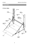
1
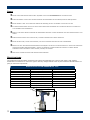
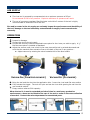
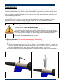
Instruction Manual Model# RK-8000M For sales, service or support call your local distributor or: 1800-BUY-RIVET www.rivet.com or 1-800-289-7483 CONTENTS Features Page 3 Safety Page 3 Specifications Page 3 Air supply Page 4 Operation Page 4 Jaw Cleaning Procedure / Jam Remedy Page 5 Maintenance / Service Oil Change/Replacement Procedure Valve Spool Assembly Trigger Page 6 Preventive Maintenance Daily Weekly Monthly Page 7 Parts Schematic Part List Page 8 Page 9 Material Safety Data Sheet Oil MSDS Page 10 Troubleshooting Page 11 Warranty Page 12 2 SAFETY DO NOT USE OUTSIDE DEISNG INTENT OR WITH EQUIPMENT THAT IS NOT RECOMMENDED BY THE MANUFACTURER. ALWAYS DISCONNECT THE AIR SUPPLY BEFORE ATTEMPTING ANY MAINTENANCE OR ADJUSTMENT/FITTING OF NOSE EQUIPMENT DO NOT OPERATE A TOOL THAT IS DIRECTED TOWARDS ANY PERSON(S) OR WITH THE MANDREL CATCHER OFF THE TOOL ALL MODIFICATIONS CARRIED OUT ON THE TOOL WITHOUT EXPRESS WRITTEN CONSENT OF THE MANUFACTURER SHALL BE DONE SO AT THE CUSTOMERS’ SOLE RESPONSIBILITY REFER TO THIS MANUAL BEFORE ATTEMPTING ANY MAINTENANCE OPERATION. DO NOT DISASSEMBLE THIS TOOL BEFORE RFERING TO THIS MANUAL. AVOID EXCESSIVE CONTACT WITH HYDRAULIC OIL, AS SOON AS POSSIBLE WASH HANDS THOROUGHLY DO NOT EXCEED 7 BAR / 100 PSI INLET PRESSURE, THE USE OF A PRESSURE REGULATOR IS HIGHLY RECOMMENDED INSPECT THE TOOL USING PREVENTITIVE MAINTENANCE TECHNIQUES AT REUGULARLY SCHEDULED INTERVALS. INSPECT FOR DAMAGE AND FUNCTION BY TRAINED COMPETANT PERSONEL. REPLACE THE PNEUMATIC CYLINDER HOUSING OR HYDRAUILIC CYLINDER HOUSING WHERNEVER THERE IS EVIDANEC OF IMPACT DAMAGE, CHIPPING, OR CRACKING. WEAR SAFETY GLASSES AND ADOPT FIRM FOOTING DURING OPERATION. SPECIFICATIONS The specifications and information contained in this manual are applicable only to the tool with which it was supplied. Industrial Rivet & Fastener Co reserve the right to make any changes without notice as part of Industrial Rivet & Fastener Co policy of continuous improvement. SPECIFICATIONS FOR RK-8000M RIVET TOOL Air Pressure Stroke Pull Force Cycle Time Noise Level Weight Vibration Hydraulic Oil Nose Pieces Nose Pieces 85-100psi 0.787 Inches 2,450 lbsF 0.9 seconds 75 dB(A) 3.3 lbs Min/Max Minimum @90psi Approximately Less than Less than 2.5m/s2 Mobil DTFE 24 3/32, 1/8 , 5/32 ,3/16 3/16 ManoBolt .9” All material rivets 12” 2.5” 11” 4” 3 AIR SUPPLY The rivet tool is powered by compressed air at an optimum pressure of 85 psi. Do not exceed 90 PSI of air pressure. Explosion and harm to operators can result. The use of a pressure regulator filter/lubricator unit within 3 meters of the tool is highly recommended to extend the life of the tool. Dirt and/or water in the air supply can seriously impact the performance and durability of the tool; damage to the tool caused by contaminated air supply is not covered under warranty. OPERATION 1 1 1... Inspect for damage 2 2 2... Connect the tool to the air supply 3 3 3... Choose and securely install the applicable nose piece for the rivets you wish to apply. A ¼” flat face nose piece is installed as standard. 4 4 4... Adjust the vacuum until rivet is held in the nose piece while tool is pointed downward and such that the mandrel after actuation flows to the back of the tool in any position... a. Adjust vacuum by rotating the valve located at left of the blue handle. FIG 1 VACUUM ON (COUNTERCLOCKWISE) FIG 2 VACUUM OFF (CLOCKWISE) 5 5 5... Bring the tool and the rivet into the application hole. Insure the rivet head flat onto surface 6 6 6... Fully actuate the trigger. The tool will cycle and set the rivet while ejecting the nail into the rear mandrel catcher. 7 7 7... Empty catcher when at 50% capacity When the tool is in use for extended periods of time in a stationary production environment, a hose can be fitted to the rear of the tool to assist in the mass collection of mandrel. Contact the sales department for associated parts. 4 JAW CLEANING PROCEDURE / JAMMED GUN REMEDY 1. Disconnect tool from air supply 2. Leaving the nose piece attached, remove the nose case 3 using the wrench provided by loosening at the wrench point. 3. Fit two wrenches, one on Jaw Case 05 and the other on 11 keeping the nut 11 stationary while unscrewing the jaw casing 05. It is important that you only unscrew the nut closest to the jaws (jaw casing) 05. DO NUT ADJUST SET NUT 13. See Fig. 5 4. Take care during removal as this jaw casing is spring loaded and contains 3 small jaws 06, a jaw pusher 07, washer 08, and a spring 09. Do not lose these pieces. Inspect 06, 07, 08, 09 for wear, cracks or damage. Replace as necessary. 5. Once removed if a mandrel has jammed the tool, dislodge the mandrel from the jaws, discard mandrel. 6. Clean Jaws 06 with a mineral spirit then and coat outside of jaws (outside only) with a drop of clean oil or a light layer of red / white grease . Be sure to coat the outside of the jaws only. See Fig. 6. Oil is preferred. 7. Replace jaws into jaw case 05. 8. Followed by jaw pusher 07, and spring 09, if necessary. 9. Re-apply jaw case 05 securely onto 11 using a wrench keeping 11 stationary.. 10. Reapply the nose case 03 securely to the tool 11. Reattach air supply. Actuate tool without rivet. Check Function. Drawing Fig. 5 Fig. 6 - Stationary 5 =light lubrication =liberal lubrication MAINTENANCE IMPORTANT: DISCONNECT THE TOOL FROM THE AIR SUPPLY OR SWITCH OFF AT VALVE (54). REMOVE NOSE ASSEMBLY OR SWIVEL HEAD COMPONENTS. All operations should be carried out on a clean bench, with clean hands in a clean area. Ensure that the new oil is perfectly clean and free from air bubbles. Care MUST be taken at all times, to ensure that no foreign matter enters the tool, or serious damage may result. Oil Priming After 100,000 cycles, or when the tool loses enough stroke and/or power to place rivets in one actuation, a priming procedure may be required. Please use the oil provided with the tool. Replacements are available at 1-800-BUY-RIVET. Do not remove the bleed screw unless you have extensive knowledge in the maintenance of hydraulic tools. - The bleed screw IS NOT AN ADJUSTMENT. - Removal of the bleed screw WILL NOT FIX A JAMED GUN. - If the bleed screw is loosed, even slightly, oil will leak out of the tool which may create an air bubble in hydraulic system causing loss of stroke and stroke cavitation. - If the bleed screw is loosed or the oil priming procedure is attempted without proper training, the tool will need to be returned to the service center for maintenance and a labor fee may be charged. Oil Priming Procedure (For trained personnel only! See above!) Disconnect air supply to tool and switch ON/OFF valve (54) to OFF position. Remove the priming pump and the excessive oil will flow out. Then clean out the excessive oil and replace the bleed screw and seal. Remove bleed screw(76) and seal(75).(see Fig 7) Fill the syringe(priming pump) with oil and screw it into the bleed screw hole. Actuate the pump be pressing down and releasing several times until resistance is felt. Overfilling the tool with oil and actuating it may result in hydraulic body fractures. (see Fig 8) Figure 7 Figure 8 6 MAINTENANCE (CONTINUED) Valve Spool Assembly Maintenance Send into authorized repair center for service. Trigger Maintenance Procedure Inspect trigger pin valve by insuring 35 has not come loose. The proper depth should be just under the valve stem. If adjustment is necessary using a fork wrench or tire valve tool, screw the trigger pin 34 into the valve stem. A very small amount of loctite243 is ok around the threaded portion only. If the trigger still fails, remove the trigger pin assembly from the valve stem and inspect the seal around the trigger pin for damage. If damaged, purchase a replacement part. Reassemble according to the previous step. PREVENTIVE MAINTENANCE In order to maintain the tool in a safe working order it is important to carry out regular maintenance as prescribed by the manufacturer. A thorough inspection replacement of all seals within the tool should be carried out after 500,000 actuations or annually, whichever is the sooner. Seal Life is dependent on the size of the rivet applied, the frequency of use in one minute, the cleanliness of the tool, proper maintenance within the time interval suggested and total number of actuations. The seal life is a limited warranty item and should only be replaced by trained personnel. Item numbers in parentheses refer to assembly drawing part numbers Daily Check for air leaks. Any damaged hoses should be replaced Lubricate the tool by pouring a 1 drop of the enclosed lubricating oil into the air inlet on the tool If there is no pressure regulator, bleed the airline to clear it of accumulated dirt or water before connecting the air hose to the tool. If there is a filter, drain it. Check for proper nose piece use depending on the size of the rivet. Remove front jaw nose assembly and clean all visible areas beneath the Nose Cap (3) with an air hose to remove metal shavings and debris. Remove jaw housing as necessary and consumable parts thoroughly with mineral spirits. Inspect for cracks or other damage to jaw or nose area. Replace if necessary. Insure that rotary valve for the vacuum on the mandrel collection unit is correctly adjusted for fastener retention Weekly Carry out procedures as per daily maintenance instructions above Clean and inspect the jaws for signs of damage or wear (groove running through the jaw serrations). Follow the instructions on page 4 for cleaning of jaws. Reassemble the tail jaws with a light coating of red grease on the outer face that contacts the jaw housing. Do not allow grease to contaminate the grooved inner face of the jaws as mandrel slippage may result. Monthly Carry out procedures as per weekly maintenance instructions above Check and replace cylinder bodies if there are signs of damage or cracks. Semi-Annually 7 Carry out procedures as per monthly maintenance instructions above Check that the stroke is greater than 1.0”. If less, follow bleeding procedure. Depending on the frequency of use, further maintenance may be required to replace the hydraulic seals. SCHEMATIC 8 SERVICE KITS & SPARE 9 OIL MATERIAL SAFETY DATA SHEET (MSDS) Priming is ALWAYS necessary after the tool has been dismantled and prior to operating. It may also be necessary to restore the full stroke after considerable use, when the stroke may be reduced and fasteners are not fully placed by one operation of the trigger Oil Details The recommended oil for priming is Mobil DTE 24 or Hyspin VG32 available in 0.51 or one gallon containers, or, you can use 30W hydraulic oil. Please see safety data below. Mobil DTE 24 or Hyspin VG 32 Oil Safety Data First Aid SKIN: Wash thoroughly with soap and water as soon as possible. Casual or short term contact requires no immediate attention. INGESTION: Seek medical attention immediately. DO NOT induce vomiting. EYES: Irrigate immediately with water for several minutes. Although NOT a primary irritant, minor irritation may occur following contact. Fire Flash point 232°C. Not classified as flammable. Suitable extinguishing media: CO2, dry powder, foam or water fog. DO NOT use water jets. Environment WASTE DISPOSAL: Through authorized contractor to a licensed site. May be incinerated. Used product may be sent for reclamation. SPILLAGE: Prevent entry into drains, sewers, and water courses. Soak up with absorbent material. Handling Wear eye protection, impervious gloves (e.g. of PVC) and a plastic apron. Use in well ventilated area. Storage No special precautions. Priming Kit To enable you to follow the priming procedure opposite, you will need to obtain a priming kit: PRIMING KIT: RK-8000LS PART NO DESCRIPTION HO HO-B Mobil DTE 24 Refill Bottle 10 TROUBLESHOOTING Item numbers in parentheses refer to assembly drawing part numbers on page 9. Problem More than one operation of the trigger needed to place fastener Tool will not grip stem of fastener Jaws will not release broken stem of fastener Jammed Gun / Cannot feed next fastener Slow cycle Tool fails to operate Fastener fails to break Insufficient Vacuum Pressure Possible Cause Tighten joints or replace components Adjust air pressure to within specification Lubricate tool at air inlet point Install new jaws adjust set nut (13) clockwise 1 rotation See Priming Procedure Service nose assembly Fit new jaws See Jaw Cleaning Procedure Tighten against locking ring Fit new spring Identify and replace Read ‘Operation’ See Jaw Cleaning Procedure Tighten nose assembly and adjust if necessary Low oil level or air bubble in hydraulic oil Broken stems jammed inside tool adjust set nut (13) counter-clockwise 1 rotation Fit new spring Tighten joints or replace components Adjust as in ‘Operating Procedure’ to 90 psi See Priming Procedure Empty mandrel collector Check if jaw pusher (7) is cracked/broken Check if Vacuum Sleeve (16) is cracked/broken Rotary valve incorrectly adjusted Air pressure below 90 psi Lack of lubrication Low air pressure Low oil level or air bubble in hydraulic oil Build up of dirt inside the nose assembly No air pressure On/Off switch is in off position Damaged trigger valve Loose pneumatic piston cover Loose stem collector Oil leaking in the air filter Air leaking in the air filter Insufficient air pressure Fastener outside tool capability Low oil level or air present in oil Insufficient Air Pressure Improper Vacuum Pressure Adjustment The part # (17) plastic sealing sleeve are broke. The air is pushed the mandrel out from the nose. 11 Remedy Air leak Insufficient air pressure Air Lubrication Worn or broken jaws Improper adjustment of set nut (13) Low oil level or air bubble in hydraulic oil Build up of dirt inside the nose assembly Worn, broken or missing jaws Build up of dirt inside the nose assembly Loose jaw housing Weak or broken spring in nose assembly Incorrect component in nose assembly Rotary valve incorrectly adjusted Build up of dirt inside the nose assembly Jaw housing, nose tip or nose casing not properly seated Improper adjustment of set nut (13) Weak or broken spring in nose assembly Air Leak or Air pressure below 90 psi Adjust vacuum pressure Adjust as in ‘Operating Procedure’ to 90 psi Lubricate tool at air inlet point Adjust air pressure to within specification See Priming Procedure Service nose assembly Adjust as in ‘Operating Procedure’ to 90 psi Slide On/Off sleeve (54) down until air is flowing See ‘Trigger Maintenance’ Page 7 Disconnect Air Pressure, Tighten all connections Disconnect Air Pressure, Tighten Cap (28) Replace part number RK8000M-63 With Berent Tool (call for service for especial tool ) Replace Number # 48 , 47 , 48 , 55 , 49 . Adjust as in ‘Operating Procedure’ to 90 psi Use more powerful tool Contact Industrial Rivet for assistance See Priming Procedure Adjust as in ‘Operating Procedure’ to 90 psi See “Operation” for proper adjustment Replace with new part Make sure the part # (13) set nut are in the correct distance. Warranty Statement: Industrial Rivet & Fastener Co. Inc. (hereinafter “IRF”), hereby warrants to the initial retail customer or original authorized distributor (“Warrantee”) only that its products will be free from defects in material and workmanship for a period of 1 year from the purchase date provided that the products are used in accordance with “IRF’s” instructions as to maintenance, operation and use. The said warranty does not extend to goods subjected to misuse, neglect, accidental/improper installation, improper maintenance or which have been altered/repaired by anyone other than the seller or its certifiably authorized agents. The said warranty does not extend to consumable components or wear components as listed in schedule A. The warrantee’s only remedy and IRF’s only obligation in the event of a defect or failure in the products, is that IRF, at its sole option, repair, replace or re work the products, but in no case shall the cost of the foregoing exceed the invoice price of the products. This warranty shall be void if any person seeking to make a claim for defective products fails to notify IRF within 30 days, or, if distributor fails to provide evidence that the product failed within 30 days of the failure. Proof and date of purchase, maintenance records as well as details regarding failure must be sent via e-mail, and a sample of the failed products sent via postal service is required for warranty evaluation. This warranty is in lieu of all other warranties, expressed or implied, including merchantability, or fitness provided for herein. Under no circumstance shall IRF be liable for incidental or consequential damages arising from the defect or failure in its products. Seller’s sole obligation under the foregoing warranty will be limited to, at Seller’s option, repair or replacement of the tool (and shipping to the buyer with transportation charges paid to any place within the contiguous 48 states). Returned goods will be evaluated by our warranty repair department and a conclusion will be determined and classified as: a) Warranty Repair (free of charge) b) Non-Warranty repair or Abuse/Neglect (Hourly rate, Schedule B) c) Maintenance (Flat Fee, Schedule B) Schedule A – Limited Warranty The following are considered consumable or wear parts and are not covered under the warranty. Consumables: Jaws, Nosepieces, Jaw Pusher, Jaw Spring Wear Parts: Mandrel Catcher, O-Rings, Pneumatic Seals, Hydraulic Seals* *Hydraulic seals have a limited warranty (6 months) and the replacement is at the sole discretion of the manufacturer. Schedule B – Maintenance/Repair Price Schedule as of 1/1/2011 Bench Fee: $ 60.00 (up to one hour) Hourly Rate: $ 60.00 per hour Flat Fee: Level 1 - Adjustments, cleaning and light repair $45.00 + parts Level 2 – Maintenance, Oil Change, plus Level 1 service $65.00 + parts Level 3 – Complete disassembly, change all seals, plus level 2 service $120.00 + parts If inspection by the seller of returned goods shows no breach of the forgoing warranty, Seller’s regular conditioning charges (Schedule B) apply. Upon this conclusion we will either repair the tool at no cost to you and return it postage paid, or call you to inform you of the repair cost. The repair will need to be approved in writing before any work is performed. A comprehensive tool service and repair program, for details contact your local area sales representative or call: Industrial Rivet & Fastener Co. 200 Paris Ave Northvale, NJ 07647 1-800-BUY-RIVET 12