1
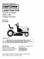
Operator's Manual
....
I RI:IFTSMFIN°
LAWN TRACTOR
18.0 HP, 42" Mower
Electric Start
6 Speed Transaxle
Model No.
917.27639
• Espafiol, p. 33
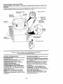
This product has a low emission engine which operates
[_
differently from previously built engines. Before you start the
engine, read and understand this Owner's Manual.
IMPORTANT:
For answers to your questions about
Read and follow all Safety
Rules and Instructions before
this product, Call:
operating this equipment.
Sears Craftsman Help Line
5 am - 5 pm, Mon- Sat
1-600-659-5917
Sears, Roebuck and Co., Hoffman Estates, IL 60179 U.S.A.
Visit our Craftsman
website:www,sears,com/craftsman
Warranty..................................................
2
SafetyRules...........................................
3
ProductSpecifications............................6
Assembly/Pre-Operation........................8
Operation..............................................
11
MaintenanceSchedule.........................17
LIMITED WARRANTY ON CRAFTSMAN
2-YEAR
Maintenance.........................................
17
Serviceand Adjustments......................22
Storage.................................................
28
Troubleshooting....................................
29
Sears Service.........................BackCover
TRACTOR AND BATTERY
ON TRACTOR
When used and maintained
according to the operator's manual instructions,
if this tractor
fails due to a defect in material or workmanship
within two years from the date of purchase, call 1-800-4-MY-HOME®
to arrange for free repair.
During the first 30 days of purchase, there will be no charge to service the product in
your home, For your convenience,
in-home warranty service wilt still be available after
the first 30 days of purchase, but a trip charge will apply. This charge will be waived if
you transport the product to an authorized Craftsman drop-off location. For the nearest
authorized
location, call 1-800-4-MY-HOME®°
Tractor warranty
coverage
does not include:
• Expendable
items which become
blades, spark plugs, air cleaners,
worn during normal
belts, and oiE filters.
use, including but not limited to
• Standard maintenance
servicing, oil changes, or tune-ups.
= Tire replacement
or repair caused by punctures from outside
thorns, stumps, or glass.
objects,
such as nails,
. Repairs necessary because of operator abuse, including but not limited to damage
caused by towing objects beyond the capability of the tractor, impacting objects that
bend the frame or crankshaft,
or over-speeding
the engine.
° Repairs necessary because of operator negligence,
including but not limited to electrical and mechanical
damage caused by improper storage, failure to use the proper
grade and amount of engine oil, failure to keep the deck clear of flammable debris,
or failure to maintain the equipment according to the instructions
contained in the
operator's manual.
° Engine (fuel system) cleaning or repairs necessary
because of fuel determined
to be
contaminated
or oxidized (stale)_ In general, fuel should be used within 30 days of its
purchase date.
= Normal deterioration
and wear of the exterior finishes, or product label replacement.
° The tractor battery, which is covered for only 90 days as stated below.
90-DAYS ON BATTERY
For ninety (90) days from the date of purchase, if the battery included with this tractor =s
defective in material or workmanship
(our testing proves it will not hold a charge), it will
be replaced free of charge.
During the first 30 days of purchase, there will be no charges to replace the battery in
your home. For your convenience,
in-home warranty service wilt still be available after
the first 30 days of purchase, but a trip charge will apply. This charge will be waived if
you transport the battery to an authorized Craftsman drop-off location. For the nearest
authorized
location, call t-800-4-MY-HOME®,
All tractor and battery warranty coverage is void if this product is used for commercial
rental purposes.
This warranty applies only while this product is within the United States.
This warranty gives you specific
vary, from state to state.
Sears, Roebuck
legal rights, and you may also have other
and Co., Hoffman
Estates,
IL 60179
or
rights, which
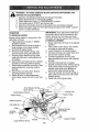
DANGER:This cutting machine is capable of amputating hands and feet and
throwing objects. Failure to observe the following safety instructions could result
in serious
injury or death°
= Never direct discharged
material toward
anyone. Avoid discharging
material
against a wall or obstruction. Material
may ricochet back toward the operator°
Stop the blades when crossing gravel
surfaces.
, Do not operate machine without the
entire grass catcher, discharge guard,
or other safety devices in place and
working.
• Slow down before turning.
° Never leave a running machine unattended. Always turn off blades, set
parking brake, stop engine, and remove
keys before dismounting_
• Disengage blades when not mowing.
Shut off engine and wait for all parts to
come to a complete stop before clean _
ing the machine, removing the grass
catcher, or unclogging the discharge
guard.
• Operate machine only in daylight or
good artificial lighto
, Do not operate the machine while under
the influence of alcohol or drugs.
o Watch for traffic when operating near or
crossing roadways.
o Use extra care when loading or unloading the machine into a trailer or truck°
o Always wear eye protection when operating machine.
, Data indicates that operators, age 60
years and above, are involved in a large
percentage of riding mower-related
injuries° These operators should evaluate
their ability to operate the riding mower
safely enough to protect themselves
and others from serious injury.
° Follow the manufacturer's
recommendation for wheel weights or counterweights.
° Keep machine free of grass, leaves or
other debris build-up which can touch
hot exhaust / engine parts and burn.
Do not allow the mower deck to plow
leaves or other debris which can cause
_)AWARNING:
In order to prevent accidental starting when setting up, transporting, adjusting or making repairs,
always disconnect spark plug wire and
place wire where it cannot contact spark
plug.
_I, WARNING:
Do not coast down a hill in
neutral, you may lose control of the tractor.
_0&.WARNING:
Tow only the attachments
that are recommended
by and comply with
specifications
of the manufacturer
of your
tractor. Use common sense when towing.
Operate only at the lowest possible speed
when on a slope. Too heavy of a load,
while on a slope, is dangerous.
Tires can
lose traction with the ground and cause
you to lose control of your tractor.
_bWARNING:
Engine exhaust, some of
its constituents,
and certain vehicle components contain or emit chemicals
known
to the State of California to cause cancer
and birth defects
harm.
or other reproductive
_WARNING:
Battery posts, terminals
and related accessories
contain lead and
lead compounds,
chemicals known to the
State of California to cause cancer and
birth defects or other reproductive
harm.
Wash hands after handling.
I. GENERAL
OPERATION
• Read, understand,
and follow all instructions on the machine and in the manual
before starting.
° Do not put hands or feet near rotating
parts or under the machine. Keep clear
of the discharge opening at all times.
° Only allow responsible adults, who are
familiar with the instructions, to operate
the machine.
° Clear the area of objects such as rocks,
toys, wire, etc, which could be picked
up and thrown by the blades.
° Be sure the area is clear of bystanders before operating.
Stop machine if
anyone enters the area°
• Never carry passengers.
° Do not mow in reverse unless absolutely necessary.
Always look down and
behind before and while backing.
build-up to occur_ Clean any oil or fuel
spillage before operating or storing the
machine. Allow machine to cool before
storage.
3
II. SLOPE
OPERATION
Slopes are a major factor related to loss of
control and tip-over accidents, which can
result in severe injury or death. Operation on all slopes requires extra caution. If
you cannot back up the slope or if you feel
uneasy on it, do not mow it.
• Mow up and down slopes, not across.
• Watch for holes, ruts, bumps, rocks, or
other hidden objects. Uneven terrain
could overturn the machine. Tall grass
can hide obstacles°
, Choose a low ground speed so that you
will not have to stop or shift while on the
slope_
• Do not mow on wet grass.Tires
may
lose traction.
Always keep the machine in gear when
going down slopes. Do not shift to neutral and coast downhill.
o Avoid starting, stopping, or turning on a
slope. If the tires lose traction, disengage the blades and proceed slowly
straight down the slope.
• Keep all movement on the slopes slow
and gradual.
Do not make sudden
changes in speed or direction, which
could cause the machine to roll over°
• Use extra care while operating machine
with grass catchers or other attachments; they can affect the stability of the
machine. Do no use on steep slopes.
• Do not try to stabilize the machine by
putting your foot on the ground.
• Do not mow near drop-offs, ditches,
or embankments.
The machine could
suddenly roll over if a wheel is over the
edge or if the edge caves in.
III, CHILDREN
Tragic accidents
can occur if the operator
is not alert to the presence
of children.
Children are often attracted to the machine
and the mowing activity.
Never assume
that children will remain where you last
saw them.
• Keep children out of the mowing area
and in the watchful care of a responsible
adult other than the operator.
• Be alert and turn machine off if a child
enters the area.
• Before and while backing, look behind
and down for small children.
o Never carry children, even with the
blades shut off. They may fall off and
be seriously injured or interfere with
safe machine operation. Children who
have been given rides in the past may
suddenly appear in the mowing area for
another ride and be run over or backed
over by the machine.
° Never allow children to operate the
machine.
° Use extra care when approaching
blind
corners, shrubs, trees, or other objects
that may block your view of a child.
IV. TOWING
• Tow only with a machine that has a
hitch designed for towing. Do not attach
towed equipment except at the hitch
point°
° Follow the manufacturer's
recommendation for weight limits for towed equipment and towing on slopes°
o Never allow children or others in or on
towed equipment.
• On slopes, the weight of the towed
equipment may cause loss of traction
and loss of control.
• Travel slowly and allow extra distance
stop.
to
V. SERVICE
SAFE
HANDLING
OF GASOLINE
To avoid personal injury or property
damage, use extreme care in handling
gasoline. Gasoline is extremely flammable
and the vapors are explosive_
• Extinguish all cigarettes, cigars, pipes,
and other sources of ignition.
• Use only approved gasoline container.
• Never remove gas cap or add fuel with
the engine running_ Atlow engine to cool
before refueling°
• Never fuel the machine indoors.
• Never store the machine or fuel container where there is an open flame,
spark, or pilot light such as on a water
heater or other appliances.
• Never fill containers inside a vehicle or
on a truck or trailer bed with plastic liner.
Always place containers on the ground
away from your' vehicle when filtingo
,
• Remove gas-powered equipment from
the truck or trailer and refuel it on the
ground° If this is not possible, then
refuel such equipment with a portable
container, rather than from a gasoline
dispenser nozzle.
• Keep the nozzle in contact with the rim
of the fuel tank or container opening at
all times until fueling is complete. Do not
use a nozzle lock-open device.
• If fuel is spilled on clothing, change
clothing immediately.
• Never overfill fuel tank. Replace gas cap
and tighten securely.
Keep machine free of grass, leaves, or
other debris bui_d-up. Clean oil or fue!
spillage and remove any fuel-soaked
debris. Allow machine to cool before
storing°
• If you strike a foreign object, stop and
inspect the machine. Repair, if necessary, before restarting.
• Never make any adjustments
or repairs
with the engine running.
• Check grass catcher components
and
the discharge guard frequently and
replace with manufacturer's
recommended parts, when necessary.
, Mower blades are sharp. Wrap the
blade or wear gloves, and use extra
caution when servicing them.
• Check brake operation frequently.
Adjust and service as required.
• Maintain or replace safety and instruction labeis, as necessary.
GENERAL
SERVICE
° Never operate machine in a closed area.
• Keep all nuts and bolts tight to be sure
the equipment is in safe working condition.
• Never tamper with safety devices. Check
their proper operation regularly.
• Before and while backing, look behind
and down for small children.
• Mow up and down slopes (15 ° Max), not
• Be sure the area is clear of bystanders before operating.
Stop machine if
anyone enters the area.
• Never carry passengers.
• Do not mow in reverse unless absolutely necessary. Always look down and
behind before and while backing,
• Never carry children, even with the
blades shut off. They may fall off and
be seriously injured or interfere with
safe machine operation. Children who
have been given rides in the past may
suddenly appear in the mowing area for
another ride and be run over or backed
over by the machine.
• Keep children out of the mowing area
and in the watchful care of a responsible
adult other than the operator.
° Be alert and turn machine off if a child
enters the area.
across,
• Choose a low ground speed so that you
will not have to stop or shift while on the
slope.
• Avoid starting, stopping, or turning on a
slope. If the tires lose traction,
disengage the blades and proceed slowly
straight down the slope_
° If machine stops while going uphil;,
disengage blades, shift into reverse and
back down slowly.
• Do not turn on slopes unless necessary, and then, turn slowly and gradually
downhill, if possible.
5
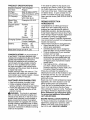
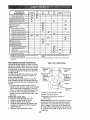
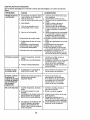
PRODUCT
SPECIFICATIONS
Gasoline Capacity
and Type:
!.25 Unleaded
Regular
Oil ]_jpe
API-SG-SL):
SAE 30 (above 32°F)
SAE 5W-30(below 32°F
Oil Capacity:
W/Filter 56 oz.
W/O Filter 48 ozo
Spark
(Gap:
Champion
RC12YC
Forward:
1st
2nd
3rd
4th
5th
6th
Reverse:
1.1
1o4
2.2
3.4
4,3
5.5
1,7
Plug:
.030")
Ground
(MPH):
Charging
Speed
System:
Battery:
3 Amps Battery
5 Amps Headlights
Amp/Hr:
Min. CCA:
Case Size:
28
230
U1R
Blade Bolt Torque: 27-35 Ft. Lbs.
CONGRATULATIONS
on your purchase of
a new tractor. It has been designed, engineered and manufactured to give you the best
possible dependability and performance.
Should you experience any problem you
cannot easily remedy, please contact a
Sears or other qualified service center.
We have competent, welHrained
representatives and the proper tools to service
or repair this tractor.
Please read and retain this manual. The
instructions will enable you to assemble
and maintain your tractor properly. Always
observe the "SAFETY RULES".
CUSTOMER
RESPONSIBILITIES
Read and observe the safety rules.
Follow a regular schedule in maintaining, caring for and using your tractor.
- Follow the instructions under"Maintenance" and "Storage" sections of this
owner's manual.
4_IbWARNING" This tractor is equipped
with an internal combustion engine and
should not be used on or near any unimproved foresbcovered, brush-covered or
grass-covered land unless the engine's
exhaust system is equipped with a spark
arrester meeting applicable local or state
laws (if any). If a spark arrester is used, it
should be maintained in effective working
order by the operator°
In the state of California the above is required by law (Section 4442 of the California Public Resources Code). Other states
may have similar laws. Federal laws apply
on federal lands° A spark arrester for the
muffler is available through your nearest
Sears service center (See REPAIR PARTS
manual).
REPAIR
PROTECTION
AGREEMENTS
Congratulations on making a smart purchase.Your new Craftsman@ product is
designed and manufactured for years of
dependable operation. But like all products,
it may require repair from time to time. That's
when having a Repair Protection Agreement
can save you money and aggravation.
Purchase a Repair Protection Agreement
now and protect yourseff from unexpected
hassle and expense_
Here's what's included in the Agreement:
•
Expert service by our 12,000 profesional repair specialists.
•
Unlimited service and no charge for
parts and labor on all covered repairs.
° Product replacement
if your covered
product can't be fixed.
,
Discount of 10% from regular price of
service and service-related
parts not
covered by the agreement; also, 10%
off regular price of preventive maintenance check.
o
Fast help by phone - phone support from a Sears representative
on
products requiring in-home repair, plus
convenient repair scheduling.
Once you purchase the Agreement, a
simple phone call is all that it takes for you
to schedule service. You can call anytime
day or night, or schedule a service appointment online°
Sears has over 12,000 professional
repair
specialists, who have access to over 4_5
million quality parts and accessories.
That's the kind of professionalism
you can
count on to help prolong the life of your
new purchase for years to come. Purchase
your Repair Protection Agreement
today!
Some limitations
and exclusions
apply.
For prices and additional information
call 1-800-827-6655.
SEARS INSTALLATION
SERVICE
For Sears professional installation of home
appliances, garage door openers, water
heaters, and other major home items, in
the U.S.A. call 1-800-4-MY-HOME®
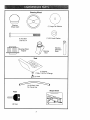
ilnlll, ii ,
n
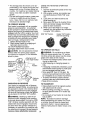
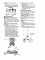
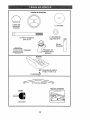
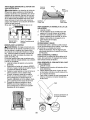
Steering Wheel
@
Steering
Wheel Insert
(1) Large Flat Washer
©
(1) 5/I6 Lock Washer
(1) Hex Bolt
5/16-18 x 4
_
Steering
Extension
Shaft
Steedng Wheel
,IIII1111tl,
I
Adapter
I
i,
Seat
(1) Oil Drain Tube
For Future Use
Slope
Keys
Sheet
(2) Keys
,i,iiiiii,in I i I
7
n,, '11111
'I
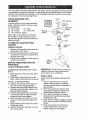
"four new tractor has been assembled at the factory with the exception of those parts left
unassembled for shipping purposes. To ensure safe and proper operation of your tractor
all parts and hardware you assemble must be tightened securely° Use the correct tools
as necessary to insure proper tightness,
TOOLS REQUIRED
ASSEMBLY
FOR
A socket wrench set will make assembly
easier° Standard wrench sizes you need
are listed below.
(1) 3/4" wrench
(1) Pliers
(1) 1/2" wrench
(1) Utility knife
(1) Tire pressure gauge
When right or left hand is mentioned in
this manual, it means when you are in
the operating position (seated behind the
steering wheel).
TO REMOVE TRACTOR FROM
CARTON
UNPACK CARTON
1. Remove all accessible loose parts and
parts boxes from carton.
2. Cut along dashed lines on all four panels of carton. Remove end panels and
lay side panels flat.
3. Check for any additional loose parts or
cartons and remove.
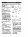
BEFORE REMOVING TRACTOR
FROM SKID
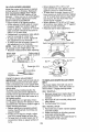
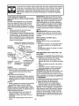
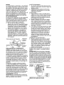
ATTACH STEERING WHEEL
ASSEMBLE
BOOT
EXTENSION
SHAFT
AND
1. Slide extension shaft onto lower steering shaft.
2. Place tabs of steering boot over tab
slots in dash and push down to secure.
iNSTALL STEERING
WHEEL
3. Position front wheels of the tractor
so
they are pointing straight forward.
Remove steering wheel adapter from
steering wheel and slide adapter onto
steering shaft extension.
5. Position steering wheel so cross bars
are horizontal (left to right) and slide
inside boot and onto adapter.
6 Assemble large flat washer, 5/16 lock
washer, 5/16 hex bolt and tighten securely.
7. Snap steering wheel insert into center
of steering wheel.
8. Remove protective materials from tractor hood and grill.
4.
IMPORTANT:
Check for and remove any
staples in skid that may puncture tires
where tractor is to roll off ski&
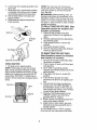
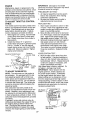
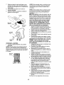
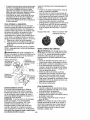
INSTALL
SEAT
Adjust seat before tightening adjustment
knob.
t. Remove adjustment
knob and flat
washer securing seat to cardboard
packing and set aside for assembly of
seat to tractor_
2.
Pivot seat upward and remove from
the cardboard packing. Remove the
cardboard packing and discar&
3. Place seat on seat pan so head of
shoulder bolt is positioned over large
slotted hole in pan.
4o Push down on seat to engage shoulder
bolt in slot and pull seat towards rear of
tractor°
5_ Pivot seat and pan forward and assemble adjustment
knob and flat
washer loosely. Do not tighten°
6. Lowerseat into operatingpositionand
sit in seat.
7. Slide seat untila comfortableposition
is reachedwhich allowsyou to press
clutch/brakepedal all the way down,
8, Get off seat withoutmovingits ad-
NOTE: You may now roll or drive your
tractor off the skid. Follow the appropriate
instruction below to remove the tractor
from the skid.
WARNING:
Before starting, read, understand and follow all instructions
in the
Operation section of this manual. Be sure
tractor is in a well-ventilated
area, Be sure
the area in front of tractor is clear of other
people and objects.
justed position.
Raise seat and tighten adjustment
knob securely.
9.
Seat
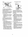
TO ROLL
Operation
TRACTOR
section
OFF SKID
for location
function
of controls)
1. Press lift lever plunger and raise
attachment lift lever to its highest
sition.
po-
2o Release parking brake by depressing
clutch/brake
pedal.
3. Place gearshift lever in neutral (N)
position.
4, Roll tractor forward off skid.
5. Remove banding holding the deflector
shield up against tractor,
Bolt
Flat Washer
\.
TO DRIVE
(See
TRACTOR
Operation
and function
Adjost /oo(Knob
CHECK
(See
and
OFF
section
SKID
for location
of controls)
1o Be sure all the above assembly steps
have been completed.
2. Check engine oil level and fill fuel tank
with gasoline.
3. Sit on seat in operating position,
depress clutch/brake
pedal and set the
parking brake.
4. Place gear shift lever in neutral (N)
position.
5. Press lift lever plunger and raise
attachment
lift lever to its highest position.
6. Remove key from bag and start the
engine (see "TO START ENGINE" in
the Operation section of this manual),
After engine has started, move throttle
control to idle (slow) position.
7. Depress clutch/brake
pedal into full
"BRAKE" position and holdo Move
gearshift lever to 1st gear,
8. Slowly release clutch/brake
pedal and
slowly drive tractor off skid.
9. Apply brake to stop tractor, set parking brake and place gearshift lever in
neutral position.
1&Turn ignition key to "STOP" position.
Continue with the instructions that follow.
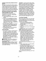
BATTERY
1_ Lift seat pan to raised position.
NOTE: If this battery is put into service
after month and year indicated on label
(label located between terminals) charge
battery for minimum of one hour at 6-10
amps. (See "BATTERY" in Maintenance
section of this manual for charging instructions).
Seat
Label
Terminal
Term
9
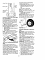
CHECK
TIRE
PRESSURE
,/CHECKLIST
The tires on your tractor were overinflared at the factory for shipping purposes.
Correct tire pressure is important for best
cutting performance°
• Reduce tire pressure to PSI shown on
tires.
Before you operate and enjoy your new
tractor, we wish to assure that you receive
the best performance
and satisfaction
from this Quality Product.
Please review the following checklist:
v" All assembly instructions
have been
completed.
CHECK DECK LEVELNESS
For best cutting results, mower housing should be properly leveled, See '"TO
LEVEL MOWER HOUSING" in the Service
and Adjustments section of this manual.
CHECK FOR PROPER
OF ALL BELTS
,/No remaining loose parts in carten_
,/Battery
is properly prepared and
charged.
_" Seat is adjusted comfortably
and tightened securely.
,/All tires are properly inflated.
(For shipping purposes, the tires were overinflated at the factory).
POSITION
See the figures that are shown for replacing motion and mower blade drive belts
in the Service and Adjustments section
of this manual° Verify that the belts are
routed correctly,
CHECK
BRAKE
v" Be sure mower deck is properly leveled
side-to-side/front-to-rear
for best cutting
results. (Tires must be properly inflated
for leveling)°
¢ Check mower and drive belts. Be sure
they are routed properly around pulleys
and inside all belt keepers.
v" Check wiring. See that all connections
are still secure and wires are properly
clamped,
While learning how to use your tractor, pay
extra attention to the following important
items:
¢ Engine oil is at proper level.
SYSTEM
After you learn how to operate your tractor, check to see that the brake is operating properly, See "TO CHECK BRAKE"
in the Service and Adjustments section of
this manual,
,/Fuel tank is filled with fresh, clean, regular unleaded gasoline_
,,/Become familiar with all controls - their
location and function.
Operate them
before you start the engine.
v" Be sure brake system is in safe operating condition.
7' Be sure Operator Presence System
and Reverse Operation System (ROS)
are working properly (See the Operation and Maintenance
sections in this
manual).
10
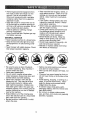
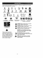
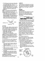
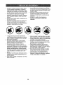
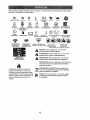
These symbols may appear on your tractor or in literature supplied with the product,
Learn and understand their meaning,
R
N
H
L
REVERSE
NEUTRAL
HIGH
LOW
I\i
CHOKE
FAST
SLOW
IGN_TI;ON SWITCH
ENGINE OFF
REVERIe
OPERATION
ENGINE ON
ENGINE START
PARKING BRAKE
SYSTEM (ROS)
;r,
LIGHTS ON
FUEL
BATTERY
REVERSE
t
FORWARD
MOWER LiFT
®$111])o
CRUISE CONTROL
CLUTCH/BRA KE
PEDAL
®@@@@
m
ATTACHMENT
CLUTCH DISENGAGED
MOWER HEIGHT
ATTACHMENT
CLUTCH ENGAGED
DANGERr KEEP HANDS
AND FEET AWAY
KEEP AREA CLEAR
SLOPE HAZARDS
(SEE SAFETY RULES SECTION)
DANGER indfcatesa hazard which, if not avoided,
will result In death or serious Injury.
FREE WHEEL
(AutornBtle Models only)
WARNING indicatesa hazard which, if not avoided,
could result In death or serious Injury.
CAUTION indicatesa hazard which,tf not avoided,
might result In minor or moderate injury,
CAUTION when used without the alert symbol,
indicates a situation that could result In damage
to the tractor and/or englneo
Failure to follow instructions
could result in serious injury or
death, The safety alert symbol
is used to identify safety information about hazards which can
result in death, serious injury
and/or property damage,
HOT SURFACES Indicates a hazard which,
If not avoided, could result In death, serious injury
and/or property damage.
FIRE Indicates a hazard which, if not avoided,
could result In death, serious Injury and/or
property damage.
11
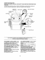
KNOW
YOUR
TRACTOR
READ THIS OWNER'S
TRACTOR
MANUAL
AND SAFETY
RULES
BEFORE
OPERATING
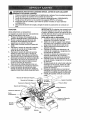
Compare the illustrations
with your tractor to familiarize yourself with the locations
various controls and adjustments,
Save this manual for future reference.
Attachment
Clutch Lever
YOUR
of
Position
Ignition Switch
Throttle/Choke
Control
ift Lever
Plunger
Light Switch
Attachment
Lift Lever
o Height
Adjustment
Indicator
Clutch!Brake
Pedal
Parking Brake Lever
Gearshift Lever
Our tractors conform to the applicable safety standards of the
American National Standards Institute,
ATTACHMENT
CLUTCH LEVER - Used
to engage the mower blades, or other attachments mounted to your tractor_
ATTACHMENT
LIFT LEVER - Used to
LIFT LEVER PLUNGER
- Used to release
attachment lift lever when changing its
position.
LIGHT SWITCH - Turns the headlights on
and off.
PARKING BRAKE LEVER - Locks clutch/
brake pedal into the brake position.
THROTTLE/CHOKE
CONTROL
- Used
for starting and controlling engine speed.
REVERSE OPERATION
SYSTEM (ROS)
"ON" POSITION
- Allows operation of
mower deck or other powered attachment
while in reverse.
raise, lower, and adjust the mower deck or
other attachments
mounted to your tractor.
CLUTCH/BRAKE
PEDAL - Used for
declutching
and braking the tractor and
starting the engine.
GEARSHIFT
LEVER - Selects the speed
and direction of tractor.
IGNITION SWITCH - Used for starting
and stopping the engine.
12
The operation of any tractor can result in foreign objects thrown into
the eyes, which can result in severe eye damage.
Always wear safety
glasses or eye shields while operating your tractor or performing any
adjustments
or repairs, We recommend
a wide vision safety mask over
spectacles or standard safety glasses.
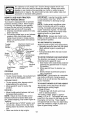
HOWTO
USEYOUR
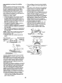
TO SET PARKING
IMPORTANT:
Leaving the ignition switch
in any position other than "STOP" wil!
cause the battery to discharge and go
dead.
NOTE: Under certain conditions when
TRACTOR
BRAKE
Your tractor is equipped with an operator
presence sensing
switch. When engine
is running, any attempt by the operator
to leave the seat without first setting the
parking brake wil! shut off the engine,
1. Depress clutch/brake
pedal all the way
down and hold,
2_ Pull parking brake lever up and release
pressure from clutch/brake
pedal.
Pedal should remain in brake position.
Make sure parking brake will hold tractor secure.
Throttle/
Choke
tractor is standing idle with the engine
running, hot engine exhaust gases may
cause "browning" of grass. To eliminate
this possibility, always stop engine when
stopping tractor on grass areas.
_J_CAUTION:
Always stop tractor completely, as described above, before leaving
the operator's position,
TO USE THROTTLE
Attachment Clutch Lever
Position
Control _
Always operate engine at full speed (fast).
° Operating engine at less than full speed
(fast) reduces engine's operating efficiency.
• Full speed (fast) offers the best mower
performance_
nition Key
_led"
Position
Parking Brake
"Engaged"
Position
"Brake"
Position
%
TO MOVE
Clutch/Brake
Pedal
Lever
STOPPING
MOWER
&
BLADES
DRIVE
-
• To stop ground drive, depress clutch/
brake pedal all the way down,
• Move gearshift
lever to neutral (N)
position.
ENGINE -
BACKWARD
Slowly release clutch/brake
start movement.
TO ADJUST
pedal to
MOWER
CUTTING
HEIGHT
The position of the attachment
lift lever
determines
the cutting height.
° Grasp lift lever,
o Press plunger with thumb and move
lever to desired position.
The cutting height range is approximately 1-1/2 to 4". The heights are measured from the ground to the blade tip with
the engine not running. These heights
are approximate
and may vary depending
upon soil conditions, height of grass and
types of grass being mowed.
• Move throttle control between half and
full speed (fast) position.
NOTE: Failure to move throttle control
between half and full speed (fast) position, before stopping, may cause engine to
"backfire".
° Turn ignition key to "STOP" position and
remove key, Always remove key when
leaving tractor to prevent unauthorized
use.
• Never use choke to stop engine.
AND
IMPORTANT:
Bring tractor to a complete
stop before shifting or changing gears,
Failure to do so wiii shorten the useful life
of your transaxte.
• To stop mower blades, move attachment
clutch lever to disengaged position.
GROUND
FORWARD
The direction and speed of movement
is
controlled by the gearshift
lever.
1. Start tractor with clutch/brake
pedal depressed and gearshift lever in neutral
(N) position.
2. Move gearshift lever to desired position.
Gearshift
"Disengaged"
Position
CONTROL
t3
USING THE REVERSE
SYSTEM -
o The average lawn should be cut to approximately
2-1/2 inches during the cool
season and to over 3 inches during hot
months, For healthier and better looking
lawns, mow often and after moderate
growth.
• For best cutting performance,
grass over
6 inches in height should be mowed
twice. Make the first cut relatively high;
the second to desired height.
TO OPERATE
t.
Depress clutch/brake
pedal all the way
down and hold.
2_ With engine running, turn ignition key
counterclockwise
to ROS "ON" position,
3. Look down and behind before and
while backing up.
Move gear shift lever to reverse (R) position and slowly release clutch/brake
pedal to start movement,
5. When use of the ROS is no longer
needed, turn the ignition key clockwise
to engine "ON" position.
4.
MOWER
Your tractor is equipped with an operator
presence sensing switch. Any attempt
by the operator to leave the seat with the
engine running and the attachment
clutch
engaged will shut off the engineoYou must
remain fully and centrally positioned in the
seat to prevent the engine from hesitating
or cutting off when operating your equipment on rough, rolling terrain or hills.
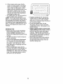
1. Select desired height of cut.
2. Start mower blades by engaging attachment clutch control.
TO STOP MOWER BLADES disengage attachment clutch control.
ROS "ON" Position
TO OPERATE
_ICAUTION:
Do not operate the mower
without either the entire grass catcher,
on mowers so equipped, or the deflector
shield in place.
Lever High Position
/
,',:_"-_Low
Position
(/(/_
_,_.
Shield
OPERATING
IN REVERSE
TO TRANSPORT
Your tractor is equipped with a Reverse
Operation System (ROS)o Any attempt by
the operator to travel in the reverse direction with the attachment clutch engaged
will shut off the engine unless the ignition
key is placed in the ROS "ON" position.
_IWARNING:
Backing
• Raise attachment
lift to highest position
with attachment lift control,
• When pushing or towing your tractor,
be sure gearshift lever is in neutral (N)
position.
• Do not push or tow tractor at more than
five (5) MPH,
NOTE: To protect hood from damage
when transporting
your tractor on a truck
or a trailer, be sure hood is closed and
secured to tractor_ Use an appropriate
means of tying hood to tractor (rope, cord,
up with the at-
tachment clutch engaged while mowing
is strongly discouraged.
Turning the ROS
"ON", to allow reverse operation with the
attachment clutch engaged, should only
be done when the operator decides it is
necessary to reposition the machine with
the attachment engaged. Do not mow in
reverse unless absolutely necessary,
ON HILLS
• If stopping is absolutely necessary, push
clutch/brake
pedal quickly to brake position and engage parking brake.
• Move gearshift
lever to 1stgear.
Be
sure you have allowed room for tractor
to roll slightly as you restart movement.
• To restart movement, slowly release
parking brake and clutch/brake
pedal.
• Make all turns slowly°
"Disen
Position
Engine "ON" Position
(Normal Operating)
_I_WARNING:
Do not drive up or down
hills with slopes greater than 15 ° and do
not drive across any slope. Use the slope
guide at the back of this manual.
• Choose the slowest speed before starting up or down hills.
• Avoid stopping or changing speed on
hills,
Attachment (
Clutch Lever
OPERATION
etc.),
14
TOWING
MENTS
CARTS
AND OTHER
ATTACH-
Tow only the attachments
that are recommended by and comply with specifications
of the manufacturer
of your tractor. Use
common sense when towing. Too heavy
of a load, while on a slope, is dangerous.
Tires can lose traction with the ground and
cause you to lose control of your tractor.
BEFORE
CHECK
STARTING
ENGINE
THE
ENGINE
OIL LEVEL
The engine in your tractor has been
shipped, from the factory, already filled
with summer weight oit.
1. Check engine oil with tractor on level
ground.
2_ Remove oil fill cap!dipstick
and wipe
clean, reinsert the dipstick and screw
cap tight, wait for a few seconds, remove and read oii level. If necessary,
add oil until "FULU' mark on dipstick is
reached. Do not overfill.
• For cold weather operation you should
change oil for easier starting (See the
oil viscosity chart in the Maintenance
section of this manual).
o To change engine oil, see the Maintenance section in this manual.
ADD GASOLINE
- Fill fuel tank to bottom of filler neck. Do
not overfill. Use fresh, clean, regular
unleaded gasoline with a minimum of
87 octane. (Use of leaded gasoline will
increase carbon and lead oxide deposits
and reduce valve life). Do not mix oil
with gasoline.
Purchase fuel in quantities that can be used within 30 days to
assure fuel freshness°
,40&.CAUTION: Wipe off any spilled oil or
fuel. Do not store, spill or use gasoline
near an open flame.
IMPORTANT:
When operating in temperatures below32°F(0°C),
use fresh, clean
winter grade gasoline to help insure good
cold weather starting.
CAUTION:
Alcohol blended fuels (calfed
gasohot or using ethanol or methanol) can
attract moisture which leads to separation and formation of acids during storage.
Acidic gas can damage the fuel system
of an engine while in storage. To avoid
engine problems, the fuel system should
be emptied before storage of 30 days
or longer. Drain the gas tank, start the
engine and let it run until the fuel lines
and carburetor are empty. Use fresh fuel
next season, See Storage Instructions for
additional information. Never use engine
or carburetor cleaner products in the fuel
tank or permanent
damage may occur.
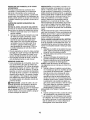
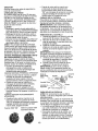
TO START
ENGINE
When starting the engine for the first time
or if the engine has run out of fuel, it will
take extra cranking time to move fuel from
the tank to the engine.
1o Sit on seat in operating position,
depress clutch/brake
pedal and set
parking brake.
2. Place gear shift lever in neutral (N)
position.
3. Move attachment clutch to disengaged
position_
4. Move throttle control to choke position.
NOTE: Before starting, read the warm
and cold starting procedures
below.
5. Insert key into ignition and turn key
clockwise to start position and release
key as soon as engine starts. Do
not run starter continuously
for more
than fifteen seconds per minute, tf the
engine does not start after several
attempts, move throttle control to fast
position, wait a few minutes and try
again. If engine still does not start,
move the throttle control back to the
choke position
WARM
above)
WEATHER
and retry.
STARTING
(50 ° F and
6.
When engine starts, move the throttle
control to the fast position.
, The attachments
and ground drive can
now be used. If the engine does not
accept the load, restart the engine and
allow it to warm up for one minute using
the choke as described above.
COLD WEATHER STARTING ( 50 ° F and
betow)
15
(
6.
When engine starts, leave throttle
control in choke position until engine
warms up and begins to run roughly.
Once rough running begins, immediately move the throttle control to the
fast position, Engine warm-up may
take from several seconds to several
minutes (the colder the temperature,
the longer the warm-up),
• The attachments
can also be used dur-
]
00272
ing the engine warm-up period,
NOTE: If at a high altitude (above 3000
feet) or in cold temperatures
(below 32 F)
the carburetor fuel mixture may need to
be adjusted for best engine performance
(see "TO ADJUST CARBURETOR"
in the
Service and Adjustments
section of this
manual).
MOWING
• If grass is extremely tall, it should be
mowed twice to reduce load and possible fire hazard from dried clippings.
Make first cut relatively high; the second
to the desired height,
, Do not mow grass when it is wet°
Wet grass will plug mower and leave
undesirable
clumps. Allow grass to dry
before mowing.
• Always operate engine at full throttle
when mowing to assure better mowing
performance
and proper discharge of
material.
Regulate ground speed by
selecting a low enough gear to give the
mower cutting performance
as well as
the quality of cut desired.
° When operating attachments,
select a
ground speed that will suit the terrain
and give best performance
of the attachment being used°
TIPS
. Mower should be properly leveled for
best mowing performance_ See "TO
LEVEL MOWER HOUSING" in the
Service and Adjustments section of this
manual.
° The left hand side of mower should be
used for trimming_
• Drive so that clippings are discharged
onto the area that has already been
cut° Have the cut area to the right of
the tractor. This will result in a more
even distribution of clippings and more
uniform cutting.
° When mowing large areas, start by
turning to the right so that clippings will
discharge away from shrubs, fences,
driveways, etc_ After one or two rounds,
mow in the opposite direction making
left hand turns until finished.
16
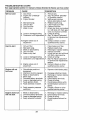
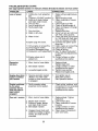
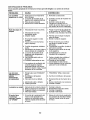
Chock Brake Operation
Check Tire Pressure
Check Operelor
Presence & ROS SysI_ms
v,...................
A Cheek for Loose Fasteners
C Check/Rap!ace Mower Blades
T Lubrication Chart
v' ........
VS
v'
0
Check Battery Level
R
clean Battery and Terminals
iv'
Dheek Transaxle Cooling
v'
.....
v"
_4
v'
_hock Mower Levelness
i C,heek V-Belts
....................
v''
V"
3h,eqk Engine O|I Leve!
,V'%
3han_e Engine 011(wtth oil filter)
3hange
Engine Oil (wlIhoul
oil fllte_
,,,
V
......
V#
V'2
3lean Air Filter
G q!eg.nAtrScreen
!
n,spect MufflerlSpark Arrestor
N
!Repiace Oil Filler (!! egutpped)
V'e
E c!,ean ,Engine cooling Fins
Replace Spark Ptug
Replace Air Filter Paper Cartridge
v'
Replace Fuel Filter
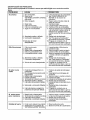
t - Chenge
more often when operating
in high ambient
temperetut_s,
under
2 - Service
in dirty or dusty
GENERAL
more
often
when
operating
a heavy
toad
or
3 - Replace blades mere eflen when mowing tn sandy soil
4 - NoI required Ifequtpped wIIhmaielenance-lree
batiery
cendtIIons
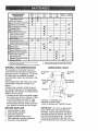
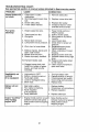
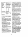
RECOMMENDATIONS
LUBRICATION
The warranty on this tractor does not
cover items that have been subjected to
operator abuse or negligence.
To receive
fu!l value from the warranty, operator
must maintain tractor as instructed in this
manual.
@ SF
Zerk
@Front Wheel
Bearing
Zerk
Some adjustments
wilt need to be made
periodically
to properly maintain your
tractor.
At least once a season, check to see if
you should make any of the adjustments
described in the Service and Adjustments
section of this manual°
EACH
Spindle
Zerk
, @Front Wheel
Bearing Zerk
®Engine
• At least once a year you should replace
the spark plug, clean or replace air filter,
and check blades and belts for wear,
A new spark plug and clean air filter
assure proper air-fuel mixture and help
your engine run better and last longer°
BEFORE
CHART
o,oo,
"(DGearshift
', Pivots
CJ.)SAE30 or 10w30 Motor Oil
@General Purpose Grease
@Refer to Maintenance "ENGINE" Section
USE
IMPORTANT:
Do not oil or grease the
pivot points which have special nylon
bearings.
Viscous lubricants will attract
dust and dirt that will shorten the life of
the self-lubricating
bearings,
If you feel
they must be lubricated, use only a dry,
powdered graphite type lubricant sparingly.
1,
2.
3,
4_
Check engine oil level.
Check brake operation.
Check tire pressure.
Check operator presence and
ROS systems for proper operation,
5. Check for loose fasteners.
17
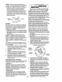
ROS "ON" Position
TRACTOR
Alwaysobserve
forming
BRAKE
safety rules when perany maintenance°
OPERATION
If tractor requires more than five (5) feet to
stop at highest speed in highest gear on a
level, dry concrete or paved surface, then
brake must be checked and adjusted. (See
"TO ADJUST BRAKE" in the Service and
Adjustments
TIRES
section
° When the engine is running with the
ignition switch in the ROS "ON" position
and the attachment
clutch is engaged,
any attempt by the operator to shift into
reverse should NOT shut off the engine.
BLADE CARE
For best results mower blades must be
of this manual).
= Maintain proper air pressure in all tires
(See "PRODUCT
SPECIFICATIONS"
section of this manual).
• Keep tires free of gasoline, oil, or insect
control chemicals which can harm rubber.
• Avoid stumps, stones, deep ruts, sharp
objects and other hazards that may
cause tire damage.
NOTE: To seat tire punctures and prevent
flat tires due to slow leaks, tire sealant
may be purchased
from your local parts
dealer_ Tire sealant also prevents tire dry
rot and corrosion.
OPERATOR
PRESENCE
SYSTEM AND
REVERSE
OPERATION
SYSTEM (ROB)
kept sharp. Replace bent or damaged
blades.
A CAUTION:
Use only a replacement
blade approved by the manufacturer
of
your tractor. Using a blade not approved
by the manufacturer
of your tractor is
hazardous, could damage your tractor and
void your warranty.
BLADE
PRESENCE
• When the engine is running, any attempt by the operator to leave the seat
without first setting the parking brake
should shut off the engine.
° When the engine is running and the
attachment clutch is engaged, any attempt by the operator to leave the seat
should shut off the engine.
° The attachment clutch should never operate unless the operator is in the seat.
CHECK REVERSE
SYSTEM
OPERATION
REMOVAL
1. Raise mower to highest position to allow access to blades.
2. Remove blade bolt, lock washer and
flat washer securing blade.
3. Install new or resharpened
blade
with trailing edge up towards deck as
shown.
IMPORTANT:
To ensure proper assembly,
center hole in blade must align with star
on mandrel assembly.
4. Reassemble
blade bolt, lock washer
and flat washer in exact order as
shown.
5. Tighten blade bolt securely (27-35 Ft.
Lbs. torque).
IMPORTANT:
Blade bolt is heat treated_
Be sure operator presence and reverse
operation systems are working properly. If
your tractor does not function as described, repair the problem immediately.
° The engine should not start unless the
brake pedal is fully depressed,
and the
attachment clutch control is in the disengaged position.
CHECK OPERATOR
SYSTEM
Engine "ON" Position
(Normal Operating)
Trailing
Edge Up_-.._ Blade
(ROS)
Mandrel
;embly
Centel
If bolt needs replacing, replace only with
approve bolt shown in the Repair Parts.
TO SHARPEN
BLADE
° When the engine is running with the ignition switch in the engine "ON" position
and the attachment clutch is engaged,
any attempt by the operator to go into
reverse should shut off the engine.
NOTE: We do not recommend
sharpening blade - but if you do, be sure the
blade is balanced.
Care should be taken to keep the blade
balanced.
An unbalanced
blade will cause
excessive vibration and eventual damage
fl
8to mower and engine.
• The blade can be sharpened with a file
or on a grinding wheel. Do not attempt
to sharpen while on the mower.
, To check blade balance, you will need a
5/8" diameter steel bolt, pin, or a cone
balancer.
(When using a cone balancer,
follow the instructions
supplied with
balancero)
NOTE; Do not use a nail for balancing
blade. The lobes of the center hole may
appear to be centered, but are noL
° Slide blade on to an unthreaded portion
of the steel bolt or pin and hold the
bolt or pin parallel with the ground. If
blade is balanced, it should remain in a
horizontal position,
tf either end of the
blade moves downward, sharpen the
heavy end until the blade is balanced_
.
V-BELTS
Check V-belts for deterioration
and wear
after !00 hours of operation and replace
if necessary. The belts are not adjustable.
Replace belts if they begin to slip from
wear.
ENGINE
LUBRICATION
Only use high quality detergent oil rated
with APi service classification
SG-SL.
Select the oil's SAE viscosity grade
according to your expected operating
temperature°
//
O
,30
-;Z{)
-1_)
I}
10
;_8
TEMPERATURE RANQE ANTICIPATED BEFORE NEXT OIL CHANGE
5/8" Bolt or Pin_---_'__
//Blade
NOTE: Although multFviscosity
oils
(5W30, 10W30 etc_) improve starting in
cold weather, the oils will result in increased oil consumption
when used above
32°E Check your engine oil level more
frequently to avoid possible engine damage from running low on oil.
Change the oil after every 50 hours of operation or at least once a year if the tractor
is not used for 50 hours in one year.
Check the crankcase oil level before starting the engine and after each eight (8)
hours of operation.
Tighten oil fill cap/
dipstick securely each time you check the
oil level.
BATTERY
Your tractor has a battery charging system
which is sufficient for normal use, However, periodic charging of the battery with
an automotive charger wilt extend its lifeo
• Keep battery and terminals clean.
° Keep battery bolts tight.
• Keep small vent holes open°
. Recharge at 6-10 amperes for 1 hour,
NOTE: The original equipment battery on
your tractor is maintenance free. Do not
attempt to open or remove caps or covers,
Adding or checking level of electrolyte is
not necessary,
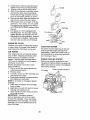
TO CHANGE
OIL
Determine temperature
range expected
before oil change, All oil must meet API
service classification
SG-SL,
. Be sure tractor is on level surface.
° Oil will drain more freely when warm.
• Catch oit in a suitable container.
1, Remove oil fill cap/dipstick_
Be careful
not to allow dirt to enter the engine
when changing oil.
2, Remove yellow cap from end of drain
valve and install the drain tube onto the
fitting.
Oil Drain Valve
TO CLEAN BATTERY AND TERMINALS
Corrosion and dirt on the battery and
terminals can cause the battery to "leak"
power_
1, Disconnect BLACK battery cable first
then RED battery cable and remove
battery from tractor,
2, Rinse the battery with plain water and
dry.
3, Clean terminals and battery cable ends
with wire brush until bright,
4, Coat terminals with grease or petroleum jelly.
5, Reinstall battery (See "REPLACING
BATTERY" in the SERVICE AND ADJUSTMENTS section of this manual),
TRANSAXLE COOLING
Keep transaxle free from build-up of dirt
and chaff which can restrict cooling.
ENGINE
Closed and
Locked
Yellow
Cap
":_
Drain
Tube
19
3,
Unlock drain valve by pushing inward
slightly and turning counterclockwise.
4. To open, pull out on the drain valve.
5, After oil has drained completely, close
and lock the drain valve by pushing
inward and turning clockwise until the
pin is in the locked position as shown.
6_ Remove the drain tube and replace the
cap onto the end of the drain valve.
7. Refill engine with oil through oil fill dipstick tube. Pour slowly. Do not overfill.
For approximate
capacity see "PRODUCT SPECIFICATIONS"
section of this
manual,
8. Use gauge on oil fill cap/dipstick
for
checking level. For accurate reading,
tighten dipstick cap securely onto the
tube before removing dipstick. Keep oil
at "FULl" line on dipstick, Tighten cap
onto the tube securely when finished.
• [/_
--%>, ,_
"__,_ _
-_j[_.
Pre-cleaner.----.J
AIR
CLEAN
Cover
, Cartridge
_yVir_._
Tabs
_'Slots
OIL FILTER
Replace the engine oil filter every season
or every other oil change if the tractor is
used more than 100 hours in one year.
j
/'_"_
Ba_
ENGINE
_.p/Handle
AIR SCREEN
Air screen must be kept free of dirt and
chaff to prevent engine damage from
overheating.
Clean with a wire brush or
compressed
air to remove dirt and stubborn dried gum fibers_
FILTER
Your engine will not run properly using a
dirty air filter. Replace pre-cleaner
after
every 25 hours of operation or every
season. Service paper cartridge every
100 hours of operation or every season,
whichever occurs first,
Service air cleaner more often under
dusty conditions.
t_ Pull up on air filter cover handle and
rotate towards engine.
2. Remove cover,
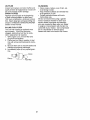
ENGINE COOLING SYSTEM
Debris may clog the engine's air cooling system, Remove blower housing and
clean area shown to prevent overheating
and engine damage.
Air Screen
3.
Carefully remove air filter cartridge and
pre-cleaner
from base.
4o Clean base carefully to prevent debris
from falling into carburetor.
NOTE: If very dirty or damaged, replace
cartridge.
5, Place new pre-cleaner and cartridge
firmly in base,
6. Align tabs on cover with slots in blower
housing and replace cover.
7. Hook handle on cover and push down
on handle to close.
IMPORTANT:
Petroleum solvents,
such as kerosene, are not to be used
to clean the cartridge.
They may cause
deterioration
of the cartridge.
Do not oil
cartridge°
Do not use pressurized air to
clean cartridge.
20
Clean out chaff and debris
MUFFLER
CLEANING
Inspect and replace corroded muffler and
spark arrester (if equipped) as it could create a fire hazard and/or damage,
SPARK PLUG(S)
• Clean engine, battery, seat, finish, etc.
of all foreign matter.
• Keep finished surfaces and wheels free
of all gasoline, oil, etc.
• Protect painted surfaces with automotive type wax°
We do not recommend using a garden
hose or pressure washer to clean your
tractor unless the engine and transmission are covered to keep water out, Water
in engine or transmission will shorten the
useful life of your tractor. Use compressed
air or a leaf blower to remove grass,
leaves and trash from tractor and mower.
Replace spark plug(s) at the beginning
of each mowing season or after every
100 hours of operation, whichever occurs
first. Spark plug type and gap setting are
shown in "PRODUCT SPECIFICATIONS"
section of this manual
IN-LINE
FUEL FILTER
The fuel filter should be replaced once
each season.
If fuel filter becomes
clogged, obstructing
fuel flow to carburetor, replacement
is required,
1_ With engine cool, remove filter and
plug fuet line sections.
2. Place new fuel filter in position in fuel
line with arrow pointing towards carburetor.
3. Be sure there are no fuel line leaks and
clamps are properly positione&
4. Immediately
wipe up any spilted gasolineo
_
Clamp ./
Clamp
\_L
A_l_-_ue
Filter
21
WARNING: ORTOADJUSTMENTS:
SERVICE
AVOID SERIOUS
1.
2.
3.
4.
5.
6.
INJURY,
BEFORE
PERFORMING
ANY
Depress clutch/brake
pedal fully and set parking brake_
Place gearshift lever in neutral (N) position.
Place attachment clutch in "DISENGAGED"
position_
Turn ignition key to "STOP" and remove key.
Make sure the blades and all moving parts have completely
stopped.
Disconnect spark plug wire from spark plug and place wire where it cannot
come in contact with plug.
IMPORTANT:
If an attachment other than
the mower deck is to be mounted on the
tractor, remove the front links and hook
the clutch spring Into square hole in frame.
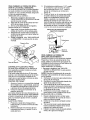
TO INSTALL MOWER
TRACTOR
TO REMOVE
MOWER
Mower will be easier to remove from the
right side of tractor,
1. Place attachment
GAGED" position.
2. Move attachment
clutch
in "DISEN-
lift lever forward
1.
Raise attachment
lift lever to its highest
position°
2o Slide mower under tractor with deflec-
to
lower mower to its lowest position°
3. Roll belt off engine pulley°
4. Remove small retainer spring, and
remove clutch spring off pulley bolt.
5. Remove large retainer spring, slide
collar off and push housing guide out
of bracket.
6_ Disconnect antFsway bar from chassis
bracket by removing retainer spring.
7. Disconnect suspension
arms from rear
deck brackets by removing retainer
springs.
8. Disconnect front links from deck by
removing retainer springs.
9. Raise lift lever to raise suspension
arms. Slide mower out from under tractor.
tor shield to right side of tractor.
Lower lift lever to its lowest position.
Connect front links to mower deck and
secure with retainer springs.
5. Connect suspension
arms to rear
deck brackets and secure with retainer
3.
4.
springs.
Connect anti-sway bar to chassis
bracket and secure with retainer spring.
7. Push clutch cable housing guide into
bracket, slide collar onto guide and
secure with large retainer spring.
8. Place flat washer and clutch spring on
idler pulley bolt and secure with small
retainer spring°
9. Install belt onto engine pulley.
6.
Small Retainer S
Clutch S
Small Retainer S
Clutch Spring
Front Link
Retainer S
Anti-Sway
Retainer Springs
Both Sides)
Housing
Guide --
Large Retainer Spring
Deflector Shield
Bracket
22
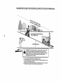
TO LEVEL
MOWER
HOUSING
• When
distance
"D" is 1/8" to 1/2"
lower at front than rear, tighten nuts "F"
against trunnion on both front links.
• To raise front of mower, loosen nut "F"
from trunnion on both front links. Tighten
nut "E" on both front links an equal number of turns. The two front links must
Adjust the mower while tractor Js parked
on level ground or driveway. Make sure
tires are properly inflated (See "PRODUCT SPECIFICATIONS"
section of this
manual).
If tires are over or undefinflated,
you will not properly adjust your mower,
SIDE-TO-SIDE
ADJUSTMENT
, Raise mower to its highest position,
° At the midpoint of both sides of mower,
measure height from bottom edge of
mower to ground.
Distance "A" on both
sides of mower should be the same or
within 1/4" of each other.
remain equal in length.
° When distance "D" is 1/8" to 1/2" lower
at front than rear, tighten nut "F" against
trunnion on both front links.
° Recheck side-to-side
adjustment.
%
o
_,_--
Mandrel
• tf adjustment is necessary, make adjustment on one side of mower only.
• To raise one side of mower, tighten lift
link adjustment
nut on that side.
, To lower one side of mower, loosen lift
link adjustment
nut on that side.
NOTE:
Each ful! turn of adjustment
nut
will change mower height about 1/8L
• Recheck measurements
after adjusting.
Bottom edge
of mower to ,___,, _--q
0rouo0
'4
A L21!C u.d
Both
Bottom edge of
rgaw,er to ground
_-
ength
l/
Trunniol
Arm
Lift Link
Adjustment N
Front Links
FRONT-TO-BACK
ADJUSTMENT
IMPORTANT:
Deck must be level side-to
side. If the following front-to-back
adjustment is necessary, be sure to adjust both
front links equa!1y so mower will stay level
side-to-side.
TO REPLACE
BELT
MOWER
BLADE
DRIVE
The mower blade drive belt may be replaced without tools. Park the tractor on
level surface. Engage parking brake.
To obtain the best cutting results, the
mower housing should be adjusted so
that the front is approximately
1/8" to 1/2"
lower than the rear when the mower is in
its highest position_
Check adjustment
on right side of tractor. Measure distance "D" directly in front
and behind the mandrel at bottom edge of
mower housing as shown.
° Before making any necessary adjustments, check that both front links are
equal in length.
° If links are not equal in length, adjust
one link to same length as other link.
• To lower front of mower loosen nut "E"
on both front links an equal number
turns.
Nut "E"
Nut
BELT REMOVALto
2.
3.
Remove mower from tractor (See "TO
REMOVE MOWER" in this section of
manual)°
Work belt off both mandrel pulleys
idler pulleys.
Pull belt away from mower.
BELT INSTALLATION
and
-
1. Work belt around both mandrel pulleys
and idler pulleys
2. Make sure belt is in all pulley grooves
and inside all belt guides.
3o Install mower (See "To Install Mower" in
this section of this manual).
of
23
Mandrel
With Parking Brake "Engaged"
Idler Pulleys
Nut "A"
Mandrel
Pulley
TO CHECK
__Ar_m_
AND ADJUST
ting
BRAKE
Your tractor is equipped with an adjustable
brake system which is mounted on the
right side of the transaxle.
If tractor requires more than five (5) feet to
stop at highest speed in highest gear on a
level, dry concrete or paved surface, then
brake must be checked and adjusted.
TO CHECK
TO REPLACE
MOTION
DRIVE
BELT
Park the tractor on level surface. Engage
parking brake_ For assistance,
there is a
belt installation guide decal on bottom side
of left footrest,
BELT REMOVAL-
BRAKE
1.
Remove mower (See "TO REMOVE
MOWER" in this section of manual),
NOTE: Observe entire motion drive belt
and position of all belt guides and keepers.
2. Remove belt from stationary idler and
clutching idler.
3, Remove belt downward from around
engine pulley.
4. Pull belt slack toward rear of tractor.
Remove belt upwards from transaxle
pulley by deflecting beIt keeper&
5, Remove belt from center span keeper
and pull belt away from tractor.
1.
Park tractor on a level, dry concrete or
paved surface, depress clutch/brake
pedal all the way down and engage
parking brake.
2. Place gear shift lever in neutral (N)
position.
The rear wheels must lock and skid when
you try to manually push the tractor forward. tf the rear wheels rotate, the brake
needs to be adjusted or the pads need to
be replaced,
TO ADJUST
Nut
BRAKE
1.
Depress clutch/brake
pedal all the way
down and engage parking brake.
2, Measure distance between brake operating arm and nut "A" on brake ro&
3. If distance is other than 1-1/2", loosen
jam nut and turn nut "A" until distance
becomes 1-1/2". Retighten jam nut
against nut "A".
4. Road test tractor for proper stopping
distance as stated above, Readjust
if necessary.
If stopping distance is
still greater than five (5) feet in highest
gear, further maintenance
is neces_
sary. Replace brake pads or contact a
Sears or other qualified service center.
BELT INSTALLATION
-
1. Carefully work new belt down between
transaxle belt keepers and onto the
input pulley,
2_ Slide belt into the center span keeper.
3. Pull belt toward front of tractor and roll
4.
5.
6.
24
around the top groove of engine pulley.
Install belt through stationary idler and
clutching idler.
Make sure belt is in all pulley grooves
and inside all belt guides and keepers.
Install mower (See "TO INSTALL
MOWER" in this section of manual).
TO REMOVE
Engine
Jan
Keeper
Stationary Idler
Transaxle
TRANSAXLE
GEAR SHIFT
TRAL ADJUSTMENT
LEVER
also prevents
NEU-
Retaining
Ring,
Axle
Cover
Square Key
(Rear Wheel Only)
TO START
TERY
Adjustment Bolt
WHEEL
ENGINE
WITH
A WEAK
BAT-
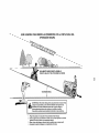
_bWARNING:
Lead-acid batteries generate explosive gases. Keep sparks, flame
and smoking materials away from batteries. Always wear eye protection when
around batteries.
If your battery is too weak to start the
engine, it should be recharged.
(See "BATTERY" in the MAINTENANCE
section of
this manual).
If "jumper cables" are used for emergency
starting, follow this procedure:
IMPORTANT:
Your tractor is equipped
with a 12 volt system. The other vehicle
must also be a 12 volt system, Do not use
your tractor battery to start other vehicles.
Gearshiff_e.v.e r_
STEERING
tire dry rot and corrosion,
Washers
The transaxte should be in neutral when
the gear shift lever is in neutral (N) (lock
gate) position. The adjustment
is preset
at the factory; however, if adjustment is
needed, proceed as follows:
1. Make sure transaxle is in neutral (N).
NOTE: When the tractor rear wheels move
freely, the transaxle is in neutral.
2. Loosen adjustment
bolt in front of the
right rear wheel
3. Position the gear shift lever )n the neutral (N) position.
4. Tighten adjustment bolt securely.
NOTE: if additional clearance is needed
to get to adjustment
bolt, move mower
deck height to the lowest position.
Neutral Lock Gate
TO ADJUST
MENT
FOR REPAIRS
Block up axle securely,
Remove axle cover, retaining ring and
washers to allow wheel removal (rear
wheels have a square key- Do not
lose),
3. Repair tire and reassemble.
NOTE; On rear wheels only: align
grooves in rear wheel hub and axle. Insert
square key,
4. Replace washers and snap retaining
ring securely in axle groove.
5. Replace axle cover°
NOTE; To seal tire punctures and prevent
flat tires due to slow leaks, purchase and
use tire sealant from Sears° Tire sealant
Center
Clutchinc
WHEEL
1.
2.
ALIGN-
If steering wheel crossbars are not
horizontal (left to right) when wheels are
positioned straight forward, remove steering wheel and reassemble with crossbars
horizontal, Tighten securely.
TO ATTACH
JUMPER
CABLES
-
1, Connect one end of the RED cabb
to the POSITIVE (+) terminal of each
battery(A-B),
taking care not to short
against tractor chassis.
2_ Connect one end of the BLACK cable
to the NEGATIVE (-) terminal (C) of
fully charged battery.
3. Connect the other end of the BLACK
cable (D) to good chassis ground,
away from fuel tank and battery,
FRONT WHEELTOE-IN/CAMBER
The front wheel toe4n and camber are not
adjustable on your tractor, If damage has
occurred to affect the front wheel toe-in or
camber, contact a Sears or other qualified
service center,
25
TO REMOVE
ORDER -
CABLES,
REVERSE
1.
BLACK
2,
then from the fully charged battery.
RED cable last from both batteries.
cable first from chassis
Weak or Dead
Battery
REPLACING
TO REPLACE HEADLIGHT
BULB
1. Raise hood.
2. Pull bulb holder out of the hole in the
and
backside of the grill.
Replace bulb in holder and push bulb
holder securely back into the hole in
the backside of the grill.
4. Close hood.
INTERLOCKS
AND RELAYS
3.
Loose or damaged wiring may
your tractor to run poorly, stop
prevent it from starting.
• Check wiring, See electrical
diagram in the Repair Parts
TO REPLACE
FUSE
Fully Charged
Battery
BATTERY
TO REMOVE
SEMBLY
HOOD
AND GRILL AS-
4, When replacing hood, be sure to reconnect the headlight wire connector.
Hood
Headlight Wire
Connector
Connect BLACK grounding cable to
negative (o) terminal with remaining
hex bolt and keps nuL Tighten securely.
Label
Keps
Hex
Bolt
(Red)
Cable
wiring
section.
1, Raise hood,
2, Unsnap headlight wire connector.
3o Stand in front of tractor, Grasp hood at
sides, tilt toward engine and lift off of
tractor°
first to prevent sparking from accidental
grounding,
t. Lift seat pan to raised position.
2. Disconnect
BLACK battery cable first
then RED battery cable and carefully
remove battery from tractor,
3. Install new battery with terminals in
same position as old battery.
4. First connect RED battery cable to
positive (+) terminal with hex bolt and
keps nut as shown. Tighten securely.
Slide terminal cover over terminal
Terminal
Ceve r
or
Replace with 20 amp automotive-type
plug-in fuse_ The fuse holder is located
behind the dash.
_,IbWARNING:
Do not short battery
terminals by allowing a wrench or any
other object to contact both terminals at
the same time, Before connecting battery,
remove metal bracelets, wristwatch bands,
rings, etc_
Positive terminal must be connected
5.
cause
running,
Negative (Black)
Cable
26
ENGINE
Maintenance, repair, or replacement of the
emission control devices and systems, which
are being done at the customers expense,
may be performed by any non-road engine
repair establishment or individual. Warranty
repairs must be performed by an authorized
engine manufacturer's service outlet°
TO ADJUST
THROTTLE
CONTROL
IMPORTANT:
Damage to the needle
valve and the seat in carburetor may result
if screw is turned in too tight.
PRELIMINARY
SETTING
-
1, Air cleaner assembly must be assem*
bled to the carburetor when making
carburetor adjustments.
2. Be sure the throttle control cable is
adjusted properly (see above).
CABLE
FINAL SETTING
The throttle control has been preset at the
factory and adjustment
should not be necessary. Check adjustment
as described
below before loosening cable. If adjustment is necessary, proceed as follows:
1. With engine not running, move throttle
control lever from slow to choke position. Slowly move lever from choke to
fast position.
2. Check that holes "A" in governor
control lever and hole in governor plate
line-up. If holes "A" are not aligned,
loosen clamp screw and move throttle
cable until holes are aligned. Tighten
clamp screw securely.
1. Start engine and allow to warm for five
minutes. Make final adjustments
with
engine running and shift/motion
control
lever in neutral (N) position°
2, Move throttle control lever to slow position. With finger, rotate and hold throttle
lever against idle speed screw. Turn
idle speed screw to attain 1750 RPM.
3. While still holding throttle lever against
idle speed screw, turn idfe mixture
valve full travel clockwise then counterclockwise
until engine runs rough.
Turn valve to a point midway between
those two positions,
Release throttle
lever.
Governor
Control Plate
ACCELERATION
TEST 4. Move throttle control lever from slow
to fast position.
If engine hesitates or
dies, turn idte mixture valve out (counterclockwise)
1/8 turn. Repeat test and
continue to adjust, if necessary, until
engine accelerates
smoothly.
High speed stop is factory adjusted.
Do
not adjust - damage may result.
IMPORTANT:
Never tamper with the
engine governor, which is factory set
for proper engine speed. Overspeeding the engine above the factory high
speed setting can be dangerous.
If you
think the engine-governed
high speed
needs adjusting, contact a Sears or other
qualified service center, which has proper
equipment
and experience
to make any
necessary adjustments.
Governor Control Lever
Clamp
Screw
TO ADJUST
Throttle
Cable
CARBURETOR
NOTE: The carburetor on this engine is
low emission.
It is equipped with an idle
fuel adjusting needle with a limiter cap,
which allows some adjustment
within the
limits allowed by the cap. Do not attempt
to remove the timiter cap. The limiter cap
cannot be removed without breaking the
adjusting needle.
The carburetor has been preset at the
factory and adjustment
should not be necessary. However, minor adjustment may
be required to compensate
for differences
in fuel, temperature,
altitude or load. If the
carburetor does need adjustment,
proceed
as follows:
In general, turning idle mixture valve in
(clockwise) decreases the supply of fuel to
the engine giving a leaner fuel/air mixture. Turning the idle mixture valve out
(counterclockwise)
increases the supply
of fuel to the engine giving a richer fuel/air
mixture.
IdteSpeed
Screw_t_C
F
-
_
"_",.'""
_Lever
Idle Mixture Valve _
With Limiter
27
Throttle
immediately
prepare your tractor for storage at the end of the season or if the tractor will not be used for 30 days or more+
blended fuels (called gasohol or using
ethanol or methanol) can attract moisture
which leads to separation and formation of
acids during storage. Acidic gas can damage the fuel system of an engine while in
storage.
• Empty the fuel tank by starting the engine and letting it run until the fuel lines
and carburetor are empty.
, Never use engine or carburetor cleaner
products in the fue! tank or permanent
damage may occur.
• Use fresh fuel next season.
_I_,WARNING:
Never store the tractor
with gasoline in the tank inside a building
where fumes may reach an open flame
or spark. Allow the engine to coo! before
storing in any enclosure,
TRACTOR
Remove mower from tractor for winter
storage. When mower
period of time, clean it
all dirt, grease, leaves,
clean, dry area.
1. Clean entire tractor
in the Maintenance
is to be stored for a
thoroughly, remove
etc. Store in a
NOTE; Fuel stabilizer is an acceptable
alternative in minimizing the formation of
fuel gum deposits during storage. Add
stabilizer to gasoline in fuel tank or storage container.
Always follow the mix ratio
found on stabilizer container.
Run engine
at least 10 minutes after adding stabilizer
to allow the stabilizer to reach the car-
(See "CLEANING"
section of this
manual)+
2o Inspect and replace belts, if necessary
(See belt replacement
instructions in
the Service and Adjustments
section of
this manual).
3+ Lubricate as shown in the Maintenance
section of this manual+
4. Be sure that all nuts, bolts and screws
are securely fastened+ Inspect moving
parts for damage, breakage and wear.
Replace if necessary,
5. Touch up all rusted or chipped paint
surfaces; sand lightly before painting.
buretor. Do not empty the gas tank and
carburetor if using fuel stabilizer+
ENGINE OIL
Drain oil (with engine warm) and replace
with clean engine oil. (See "ENGINE" in
the Maintenance
section of this manual).
CYLINDER(S)
14 Remove spark plug(s)+
2. Pour one ounce of oil through spark
plug hole(s) into cylinder(s)o
3. Turn ignition key to "START" position
for a few seconds to distribute oit.
BATTERY
• Fully charge the battery for storage_
° After a period of time in storage, battery
may require recharging+
° To help prevent corrosion and power
leakage during long periods of storage,
battery cables should be disconnected
and battery cleaned thoroughly
(see "TO
CLEAN BATTERY AND TERMINALS"
in
4.
Replace
with new spark plug(s).
OTHER
• Do not store gasoline
to another°
from one season
• Replace your gasoline can if your can
starts to rust. Rust and/or dirt in your
gasoline will cause problems.
° If possible, store your tractor indoors
and cover it to give protection from dust
and dirt.
° Cover your tractor with a suitable pro+
tective cover that does not retain mois-
the Maintenance
section of this manual).
• After cleaning, leave cables disconnected and place cables where they
cannot come in contact with battery
terminals°
° If battery is removed from tractor for
storage, do not store battery directly on
concrete or damp surfaces.
ture. Do not use plastic, Plastic cannot
breathe which allows condensation
to
ENGINE
form and will cause your tractor to rust,
IMPORTANT:
Never cover tractor whiie
engine and exhaust areas are still warm.
FUEL SYSTEM
IMPORTANT:
It is important to prevent
gum deposits from forming in essential
fuel system parts such as carburetor, fuel
hose, or tank during storage. Also, alcohol
28
TROUBLESHOOTING
CHART:
See appropriate section in manual unless directed to Sears service center
PROBLEM
Will not start
CA__USE
CORRECTION
.....
1_ Out of fuel,
2. Engine not "CHOKED"
80 Loose or damaged wiring,
9, Carburetor out of adjustment,
1. Fill fuel tank.
2. See "TO START ENGINE"
in Operation section.
3_ Wait several minutes
before attempting to start°
4. Replace spark plug.
5_ Clean/replace
air filter.
6. Replace fuel filter.
7. Empty fuel tank and carbure.
tor, refill tank with fresh gasoline and replace fue! filter.
8. Check all wiring.
9. See "To Adjust Carburetor"
10. Engine valves out of
adjustment.
in Service and Adjustments
section,
10, Contact a Sears or other
qualified service center.
1.
2.
&
4_
5.
.
.
3.
4o
5.
properiy_
3. Engine flooded.
4.
5_
6o
7
Hard to start
Bad spark plug.
Dirty air filter_
Dirty fuel filter
Water in fuel.
Dirty air fitter_
Bad spark plug.
Weak or dead battery.
Dirty fuel filter
Stale or dirty fuel.
6. Loose or damaged wiring.
7, Carburetor out of adjustment.
8, Engine valves out of
adjustment.
Engine will not
turn over
1. Clutch/brake
pedal not
depressed.
2. Attachment clutch is engaged.
3. Weak or dead battery.
4_ Blown fuse.
5.
6.
7_
8.
g_
Engine clicks but
will not start
1,
2,
3o
4,
Corroded battery terminals.
Loose or damaged wiring.
Faulty ignition switch.
Faulty solenoid or starter.
Faulty oPerator presence
switch(es),
Weak or dead battery.
Corroded battery terminals.
Loose or damaged wiring_
Faulty solenoid or starter.
29
Clean/replace
air filter.
Replace spark plug_
Recharge or replace battery.
Replace fuel filter.
Empty fuel tank and refill tank
with fresh, clean gasoline.
6. Check all wiring.
7. See "To Adjust Carburetor"
in Service and Adjustments
section.
8o Contact a Sears or other
qualified service center.
1.
Depress
clutch/brake
pedal.
2_
3.
4.
5.
6o
7.
8.
Disengage attachment clutch.
Recharge or replace battery.
Replace fuse.
Clean battery terminals.
Check all wiring.
Check/replace ignition switch°
Check/replace
solenoid or
starter.
9. Contact a Sears or other
qualified service center,
t. Recharge or replace battery.
2. Clean battery terminals.
3. Check all wiring.
4. Check!replace
solenoid or
starter.
TROUBLESHOOTING
CHART:
See appropriate section in manual unless directed to Sears service center
PROBLEM
Loss of power
CAUSE
1.
2.
3.
4
5_
6.
CORRECTION
Cutting too much grass/too
fast.
Throttle in "CHOKE" position.
Build-up of grass, leaves
and trash under mowen
Dirty air filter..
Low oil level/dirty oil.
Faulty spark plug.
7 Dirty fuel filter.
8. Stale or dirty fuel
9. Water in fuel.
lO.Spark
11.
12.
13.
14.
plug wire loose.
Dirty engine air screen/fins.
Dirty/clogged
muffler.
Loose or damaged wiring°
Carburetor out of adjustmenL
15. Engine valves
adjustment.
Excessive
vibration
out of
1. Worn, bent or loose blade.
2. Bent blade mandrel.
3, Loose/damaged
Engine dies when
tractor is shifted
into reverse
-E_nginecontinues
to run when
operator leaves
seat with attachment clutch
engaged
,
,
Poor cut - uneven
part(s).
Reverse operation system
(ROS) is not "ON" while
mower or other attachment
is engaged.
1. Replace blade.
Tighten blade bolt.
2. Contact a Sears or other
qualified service center.
3, Tighten loose part(s).
Replace damaged parts.
1. Turn i_nition key to
ROS ON position.
See Operation section.
Faulty operator-safety
presence control system.
Worn, bent or loose blade.
Mower deck not level,
Buildup of grass, leaves,
and trash under mower.
4. Bent blade mandrel.
2.
3.
5.
1. Raise cutting height/reduce
speed_
2. Adjust throttle control.
3. Clean underside of mower
housing°
4. Clean/replace
air filter°
5. Check oil level/change
oil
6. Clean and regap or change
spark plug.
7. Replace fuel filter.
8. Empty fuel tank and refill tank
with fresh, clean gasoline.
9. Empty fuel tank and carburetor, refill tank with fresh gasoline and replace fuel filter.
lO.Connect
and tighten spark
plug wire.
11. Clean engine air screen/fins.
12. Clean/replace
muffler.
13.Check all wiring.
14_See "To Adjust Carburetor"
in Service and Adjustments
section.
15. Contact a Sears or other
qualified service center.
Clogged mower deck vent
holes from buildup of grass,
leaves, and trash around
mandrels.
30
,
!.
Check wiring, switches and
connections° If not corrected
contact Sears or other
qualified service center.
Replace blade_ Tighten
blade bolto
2. Level mower deck.
3o Clean underside of mower
housing.
4. Contact a Sears or other
qualified service center.
5o Clean around mandrels to
open vent holes.
TROUBLESHOOTING
CHART:
See appropriate section in manual unless directed to Sears service center
PROBLEM
Mower blades will
not rotate
Poor grass
discharge
CAUSE
CORRECTION
1. Obstruction
in clutch
mechanism.
2. Worn/damaged
mower
belt.
1o Remove
obstruction_
2.
Replace
mower drive belt.
3. Frozen idler pulley_
4o Frozen blade mandrel.
3.
4.
Replace idler pulley.
Contact a Sears or other
qualified service center.
1. Engine
1. Place throttle control in
"FAST" position.
2o Shift to slower speed.
3. Allow grass to dry before
mowing°
4. Level mower deck°
drive
speed too slow.
2.
3.
Travel speed too fast.
Wet grass.
4.
5,
Mower deck not level,
Low/uneven tire air pressure.
6o Worn, bent or loose blade°
7.
8.
9.
Buildup of grass, leaves and
trash under mower.
Mower drive belt worn.
Blades improperly installed°
10. Improper blades used,
11. Clogged mower deck vent
holes from buildup of grass,
leaves, and trash around
mandrels.
Headlight(s) not
working
(if so equipped)
I.
2,
3.
4.
5.
Battery will not
charge
1, Bad battery cell(s).
2. Poor cable connections,
3. Faulty regulator
(if so equipped).
4o Faulty alternator.
Engine "backfires"
when turning
engine "OFF"
Light switch is"OFF".
Bulb(s) or lamp(s) burned out.
Faulty light switch,
Loose or damaged wiring°
Blown fuse,
Engine throttle control not set
between half and full speed
(fast) position before stopping
engine.
31
5.
Check tires for proper air
pressure°
6. Replace/sharpen
blade.
Tighten blade bolt.
7. Clean underside of mower
housing.
8. Replace mower drive belt.
9. Reinstall blades sharp edge
down.
10. Replace with blades listed
in this manual.
1 t. Clean around mandrels to
open vent holes.
.
•
3.
4.
5.
Turn light switch "ON".
Replace bulb(s) or lamp(s).
Check/replace
light switch.
Check wiring and connections
Replace fuse.
. Check/clean
Replace battery.
all connections.
& Replace regulator.
4.
,
Replace
alternator.
Move throttle
control
between half and full speed
(fast) position before
stopping engine.
SUGGESTED
GUIDE
FOR SIGHTING
SLOPES
FOR SAFE
ONLY RIDE UP AND DOWN HILL,
NOT ACROSS HILL
co
ro
15 DEGREES
!
_ _
MAX.
il _M,
down the
face of
slopes,
never across
the face.
Do nottomow
slopes
greater
than
15 degrees.
Make turns
gradually
prevent
tipping
or
loss
of
control.
Exercise
extreme
caution
whenup and
WARNING: To avoid serious injury, operate your tractor
ii"
changing direction on slopes.
1. Fold this page along dotted line indicated above.
2. Hold page before you so that its left edge is vertically parallel to a tree
trunk or other upright structure.
3. Sight across the fotd in the direction of hilt slope you want to measure.
4. Compare the angle of the fold with the slope of the hill.
OPERATION
2 AltOS
PARA ELTRACTOR
Siempre que su uso y mantenimiento se reaticen de acuerdo alas instrucciones del Manual det
Operador, si este tractor Ilega a fallar debido a un defecto de materiales o de fabdcaci6n dentro
de un plazo de dos (2) eros a partir de la fecha de compra, llame al 1+800-4-MY-HOME®, o bien
gestione una reparaciSn sin cargo.
Durante los primeros 30 dias de dicho plazo, no se te cobrar_, nada por reparar el producto en su
domiciiio. Para su conveniencia, podr_ seguir contando con la posibilidad de obtener el service de
la garantfa a domicilio una vez transcurddos los primeros 30 dies, pero en ese caso deber& pagar
un vi_ttico+ Usted podr& evitarse el costo del vi#.tico si Ileva el producto a un centro de servicios
autorizado de Craftsman. Pare saber cub.l le queda m&s cerca, Ifame al 1-800-4-MY-HOME®.
La cobertura de la garantfa del tractor no incluye:
• Artfculos desgastables que se desgastan durante et uso normal, incluyendo pero no limitado a:
cuchillas, buj[as, filtros de aire, correas y filtros de aceite.
• Servicio de mantenimiento est&ndar, cambios del aceite o puestas a punto.
• Cambio de Ilantas o reparaci6n de 6stas debido a pefforaciones producidas por objetos extra5os, tales como clavos, espinas, tocones o vidrio.
• Reparaciones necesarias debido al abuso del operador, incluyendo pero no limitado a; los da#,os
causados por el remolque de objetos m#.s all& de la capacidad del equipo conducible, el impacto
de objetos qua dobtan el marco o el #,rbol de manivela, o la vetocidad excesiva del motor.
• Reparaciones necesarias debido a Ia negligencia del operador, incluyendo pero no limitado a;
el daSo el_ctrico y mac6.nico causado por un almacenamiento inadecuado, ta falta de utilizer
el grado y la cantidad apropiada de aceite de motor, la falta de mantener la cubierta libre de
escombros inftamables, o la falta de mantener el equipo seg_n las instrucciones que se encuentran en el manual del dueSo_
• Limpieza o reparaciones del motor (sistema de carburante) causadas por un combustible contaminado o oxidado (viejo). En general, el combustible debe ser utilizado en el ptazo de treinta
(30) dfas de la fecha de compra+
° Deterioro y desgaste normal de los acabadcs exteriores o sustituci6n de etiquetas del producto.
• La baterl'a, la cual est,. cubierta por s61o 90 d[as, como se establece a continuaci6n.
90 D|AS PARA LA BATER|A
Per un plazo de noventa (90) dfas a partir de la fecha de compra, si la bateria que viene con este
tractor presenta alg_n defecto de materiales o de fabricaci6n (el probarla, comprobamos que no
mantiene la carga), le ser& reemplazada sin costo+
Durante los primeros 30 d[as a partir de la compra, no se le cobrar& por realizar el reemplazo de la
bateria en su domicilioo Pare su conveniencia, podr& seguir contando con la posibilidad de obtener
el servicio de la garantfa a domicilio, pero en ese caso, deber#, pager un vi,_tico. Usted podr& evitarse el costo del vi&tico si lleva la baterfa a un Centro de Servicios autorizado de Craftsman. Para
saber cu=51le queda m_s cerca, llame a! 1-800-4-MY-HOME®+
La totalidad de la cobertura de la garantia del tractor y la baterfa quedar& sin efecto en caso que et
producto sea utilizado con fines comerciales o de alquiler.
La presente garanti'a s61o serb, aplicable si el producto se encuentra dentro de los Estados Unidos+
La presente garantia le otorga derechos legales especificos+ Por otra parte, puede que usted
tenga otros derechos, los cuales varfan de estado a estado+
Sears,
Roebuck
and Co., Hoffman
Estates,
33
IL 60179
PELIGRO: Esta Maquina cortadora es capaz de amputar las manosy los pies y de lanzar
objetos, si no se observan las instrucciones de seguridad siguientes se pueden producir
lesiones graves o la muerte.
_LADVERTENCIA: Siempre desconecte el
alambre de la bujfa y pSngalo donde no pueda
entrar en contacto con la bujla, para evitar el
arranque per accidente, durante la preparaciSn
el transporte, el ajuste o cuando se hacen
reparaclones,
_ADVERTENClA:
No avance cuesta abajo a
punto muerto ya que podria perder el control
del tractor,
° No hacer funcionar fa m_quina sin el
captador de hierba entera, la protecci6n de
descarga u otros dispositivos de seguridad
en su lugar yen buenas condiciones
* Ralentizar antes de girar
- Nunca dejar una m&quina encendida sin vigilancia Apagar siempre las cuchillas, poner el
franc de estacionamiento, parar el motor, y
quitar las Ifaves antes de bajar,
. Desconectar las cuchitlas cuando no se
corta Apagar el motor y esperar que todas
las partes est6n completamente paradas
antes de limpiar la m&quina, quitar el captador de hierba, o desatascar la protecci6n de
descarga
. Hacer funcionar ta m_quina s61o con la luz
del dia o luz artificial buena
• No hacer funcionar la m_quina estando bajo
los efectos de alcohol o droga
• Poner atenciSn al tra fico cuando se opera
cerca de callas o se cruzan
. Poner la m_xima atenciSn al cargar o descargar la m&quina en una caravana o cami6n
° Llevar siempre galas de protecci6n cuando
se hace funcionar la m&quinao
. Los dates indican qua los operadores a
partir de los 60 aSos est&n afectados per
un gran porcentaje de heridas relativas ala
conducci6n del cortac_sped Estos operadores tendrfan que evaluar su habilidad de
hacer funcionar el cortac_sped de mode Io
bastante seguro para proteger a sf mismos y
a otras personas de heridas graves°
° Seguir las recomendaciones del fabricante
para los pesos y contrapesos de tas ruedas
. Mantener la m&quina libra de hierba, hojas
u otros escombros que pueden tocar el
tube de escape / partes del motor calientes
y quemarse. No permitir que el puente del
cortac_sped cargue hojas u otros residues
qua pueden causar acumutaciones Limpiar
toda salpicadura de aceite o carburante antes de hacer operaciones sobre la m_quina o
guardarlao Dejarla enfriar antes de guardarla
II FUNCIONAMIENTO
EN PENDIENTES
Las pendientes son el mayor factor de accidentes relatives ala p6rdida de control y vuelco,
que pueden causer severas heridas o muerte
El funcionamiento en pendientes requiere una
atenci6n extra Si no es posible hacer marcha
atr&s en una pendiente o site sientes incomode, no la cortes
. Cortar hacia arriba y abajo de una pendiente.
no de mode horizontal
• Porter atenciones a los hoyos, las farces, los
buttes, las piedras u otros objetos escondidos El terreno irregular puede volcar la
m_quina La hierba alta puede esconder
obst_culos
_I, ADVERTENClA: Remolque solamente los
accesorios recomendados y conformes alas
caracteristicas indicadas per el fabricante de
su tractor. Tenga cuidado y prudencia al utilizar
el tractor. Cuando se encuentre en un declive,
oper utilizando exclusivamente la vetocidad
m#.s baja. En case de un declive una carga excesiva podria resultar peligrosa. Los neumb.ticos pueden perder la tracci6n con el suelo y
hacerte perder el control de su tractor,
•_-ADVERTENClA:
El tube de escape del
motor, algunos de sus constituyentes y algunos
componentes del vehicufo contienen o desprenden productos qufmicos conocidos en el Estado
de California come cause de cb,ncer y defectos
al nacimiento u otros daSos reproductivos
_ADVERTENClA:
Los bornes, terminales y
accesorios relatives de la baterfa contienen
plomo o compuestos de plomo, productos
qufmicos conocidos en el Estado de California
come causa de c&ncer y defectos al nacimiento
u otros daSos reproductivos Laver las manes
despu_s de manipularloso
I. FUNCIONAMIENTO
GENERAL
• Leer, entender y seguir todas las instrucciones sobre la m&quina y en el manual antes
de empezaro
. No poner las manes o los pies cerca de
partes giratorias o debajo de la m_quinao
mantener siempre limpia ta abertura de
descarga
• Permitir el funcionamiento de la m_quina
s61o a adultos qua tengan familiaridad con
las instrucciones
• Limpiar el _rea de objetos come piedras,
juguetes, cables, etc que pueden ser recogidos y disparados con las cuchiltas_
• Asegurarse de que el &tea est_ libre de otras
personas antes de ponerla en marcha. Parer
la m_quina si alguien entre en el _rea_
• Nunca !lever pasajeros.
° No cortar marcha atr&s al no ser absolutamente necesario, Mirar siempre abajo y
delante mientras se precede atr_so
• Nunca dirigir el material descargado hacia
nadie, Evitar descargar material contra
paredes u obstrucciones. El material podrfa
rebotar hacia el operador. Parer tas cuchillas
cuando se pasan superficies de grave.
34
• Escoger una velocidad de marcha baja de
modo qua no sea necesario pararse o cambiar estando en una pendiente.
° No cortar la hierba mojadao Las ruedas
pueden perder tracci6n_
Porter siempre una marcha cuando se est&
en pendientes. No poner en punto muerto e
ir cuesta abajo,
• Evitararrancar, pararse o girar en una
pendiente. Si las ruedas pierden tracci6n,
desconectar las cuchillas y proceder despacio cuesta abajo en la pendiente.
• Mantener todo los movimientos en las pendientes lentos y gradual. No hacer cambios
repentinos de velocidad o direcci6n, ya que
pueden causar el escape de la m#,quina.
• Poner la m_xima atenci6n cuando la m&quina funciona con captadores de hierba
u otros dispositivos enganchados; pueden
afectar la estabilidad de la m_quina_ No usar
en pendientes empinados.
• No intentar estabilizar la m#,quina poniendo
el pie en el terrenoo
• No cortar cerca de bajadas, cunetas y orillas°
Las m&quina puede volcarse improvisamente
si una rueda est#, en el borde o se hunde.
• Nunca permitir que niSos u otras personas
est#n dentro del equipo por remotcar.
• En pendientes, el peso del equipo remolcado
puede causar la p6rdida de tracci6n y ta
p_rdida de control
, Viajar despacio y dejar m&s distancia para
frenar.
V. SERVlClO
MANIPULACi6N
SEGURA DE LA
GASOLINA
Para evitar heridas personales o daSos alas
cosas, poner el m&ximo cuidado a ia hora de
manipular la gasolinao La gasolina es extremamente inffamable y fos vapores son explosivos.
• Apagar todos los cigarrillos, cigarros, pipas y
otras fuentes de ignici6n.
° Usar s61o contenedores para gasolina aprobados.
° Nunca quitar el tap6n de ta gasolina o aRadir
carburante con el motor en marcha, dejar
enfriar el motor antes del abastecimiento de
la gasolinao
° Nunca abastecer la m#.quina al interior de un
local.
° Nunca guardar la m&quina o el contenedor
det carburante donde haya una llama abierta,
m.NI£OS
chispas o una luz piloto como un calentador
Si el operador no pone atenci6n a la presencia
de agua u otros dispositivoso
de los niSos pueden ocurrir accidentes tr_.giCOSo ° Nunca llenar los contenedores al interior de
Los niS,os a menudo estAn atrafdos por la m_.un vehfculo o en una caravana o cami6n
quina y las actividad de cortar. No dar por hecho
recubiertos con un forro de pt_.stico. Colocar
de que los niSos se queden adonde estaban la
siempre los contenedores en el terreno iejos
t_itima vez que los vistes.
del vehfculo cuando se est& Ilenando°
• Mantener los niBos fuera del _.rea de corte y
= Quitar el equipo de gas del cami6n o caravigilados por un adulto responsable que no
vana y abastecerlo en el terreno. Si no es
sea el operador.
posible, abastecer dicho equipo con un con° Estar alerta y apagar la m&quina si un ni5os
tenedor port&til, m&s bien que de un surtidor
entra en el &rea.
de gasolina.
• Antes y durante la marcha atr&s, mirar adel• Mantener la boquitla a contacto del borde
ante y abajo para ver si hay niSos pequeSoso
de! dep6sito de carburante o la abertura del
, Nunca Ilevar ni_os, incluso si hay las
contenedor durante toda la operaci6n de
cuchillas apagadas. Podrian caer y herirse
abastecimiento. No utiiizar un dispositivo con
sedamente o interferir con el funcionamiento
boquilla cerrada-abierta.
seguro de la m_.quina, los niSos que se han
° Si se vierte carburante sobre la ropa, cambiIlevado precedentemente pueden aparecer
arse la ropa inmediatamente.
de pronto en el _rea de corte por otro paseo
° Nunca Ilenar et dep6sito m_s de Io debido.
y ser atropetlados o tumbados por la m#,Volver a colocar el tap6n del gas y cerrar de
modo firmeo
quina_
,, Nunca dejar que los niBos manipulen la
OPERACIONES
DE SERVIClO
m_quina,
GENERALES
• Tenet el m,_ximo cuidado cuando se acerca
a cantos ciegos, arbustos, _rboles u otros
• Nunca hacer funcionar la m_quina en un
&rea cerrada,
objetos que pueden impedir la vista de niSos_
IV. REMOLQUE
° Mantener todas Ias tuercas y pernos apretados para asegurarse de que trabaja en
• Remolcar s61o con una m_quina que tenga
condiciones seguras,
un gancho diseSado para remolcar. En• Nunca modificar los dispositivos de seguriganchar el equipo o remolcar s61o en el
dad. Controlar su correcto funcienamiento
punto dispuesto al efectoo
regularmente_
o Seguir las recomendaciones del productor
con respecto a los l[mites del equipo por
remolcar y el remolque en pendientes.
35
, Mantener la m_quina libre de hierba, hojas
u otros residuos acumulados Limpiar las
salpicaduras de aceite o carburante y quitar
cualquier cosa mojada con carburante Dejar
que 1a m&quina se enfrfe antes de guardarla
• Si se golpea un objeto ajeno, hay que
pararse e inspeccionar la m_quina Reparar,
si es necesario, antes de volver a poner en
marcha
• Nunca hacer ning0n ajuste o reparaci6n con
el motor en funci6n,
• Controlar los componentes del captador de
hierba y Ia protecci6n de la descarga frecuentemente y sustituir con partes recomen
dadas por el fabricante, en su caso
• Las cuchillas det cortac_sped son afitadas
Envolver la cuchilla, ponerse guantes y poner
la m=ixima atenci6n cuando se hacen operaciones en elias
• Controlar el funcionamiento del freno frecuentemente Ajustar y hacer las opera
clones de mantenimiento cuando eso sea
necesarioo
o Mantener y sustituir las etiquetas de
seguridad e instrucci6n, cuando sea
necesario
•
• Antes y durante la marcha atr#,s, mirar adelante y abajo para ver si hay nifos peque5os
• Cortar hacia ardba y abajo de una pendiente
(15 ° M_ix), no de modo horizontal
• Escoger una velocidad de marcha baja de
modo que no sea necesario pararse o cambJar estando en una pendiente°
° Evitar arrancar, pararse o girar en una
pendiente Si las ruedas pierden tracci6n,
desconectar las cuchillas y proceder despacio cuesta abajo en la pendiente
° Si la m&quina se para mientras va cuesta
arriba, desconectar Jas cuchiJlas, poner la
marcha atr_ts y ir hacia atr_s despacio
• No girar estando en pendientes si no es
necesario y luego girar despacio y gradualmente cuesta abajo, si es posible
o
•
o
°
°
Asegurarse de que el &tea est_ libre de
otras personas antes de ponerla en marcha
para la m#quina si alguien entra en el _rea
Nunca Ilevar pasajeros°
No corlar marcha atr#,s a! no ser absolutamente necesario Mirar siempre abajo y
detante mientras se precede atr&s
Nunca Ilevar ni_os, incluso si hay las
cuchillas apagadas Podrfan caer y herirse
seriamente o interferir con et funcionamiento
seguro de la mAquinao los nifios que se han
Ilevado precedentemente pueden aparecer
de pronto en el _irea de corte pot otro paseo
y ser atropellados o tumbados por la m&quina
Mantener los niSos fuera del _rea de corte y
vigilados por un adulto responsable que no
sea et operador
Estar alerta y apagar la m&quina si un niRos
entra en el _rea
36
ESPECIFICACIONES
DEL PRODUCTO
Capacidad y Tipo
de Gasoline
1.25 Galones
Regular Sin Ptome
Tipo de Aceite
API-SG-SL):
SAE 30 (Sobre 32°F)
SAE 5W30 (Deabajo 32°F)
Capacidad de
Aceite:
Con Filtro:
Sin Filtro:
Bujfa:
(Abertura: .030")
Velocidad de
Recarddo(MPH):
Champion RC12YC
Sistema de Carga:
3 Amps Bateria
5 Amps Luces
AMP/HR:
MIN_ CCA:
Mode_o Tamale:
Bater[a;
TorsiSn de! Perno
de la Cuchilla:
En el estado de California, la ley exige Io anterior (Secci6n 4442 del "California Public Resources Code"). Otros estados pueden center
con otras leyes parecidas. Los leyes federales
se aplican en ta tierras federales. Su centre de
Servicio mAs cercano tiene dispontbte amortiguadores de chispas pare el silenciador. (Vea ta
secciSn de Partes de Repuesto en el manual)
56 oz_
48 oz.
Marcha Hacia AdeTante:
1sT
1.2
2_a
1.5
3_
2.4
4th
&4
5 t"
4.3
6 _h
5.5
Marcha Atr_.s: 1.7
28
230
U1R
27-35 Ft. Lbs.
FELICITACIONES per ta compra de su tractor.
Ha side diseRado, planificado y fabricado pare
darle la mejor confiabilidad y el meier rendimiento posible.
En el case de que se encuentre con cualquier
problema que no pueda sotucionar f#,cilrnente,
haga el favor de ponerse en contacto con un
centre de servicio Sears o con un otto centre
de servicio cualificado. Cuenta con representantes bien capacitados y competentes y con las
herramientas adecuadas pare darte servicio o
pare reparar este tractor.
Haga el favor de leer y de guardar este manual.
Estas instruc-ciones le permitir_n mentor y
mantener su unidad en forma adecuadao Siempro observe las "REGLAS DE SEGURIDAD?
RESPONSABILIDADES
DEL CLIENTE
, Lea y observe las reglas de seguridado
• Siga un programa regular de mantenimiento,
cuidado y use de su tractor.
• SJga las instrucctones descritas en tas secclones "Mantenimiento" y "Atmacenamiento"
de este Manual del Due5o.
_,ADVERTENGIA:
Este tractor viene equipado con un motor de combusti6n interna y no
se debe user sobre, o cerca, de un terreno no
desarrollado cubierto de bosques,
de arbustos o de c6sped, o menos que el
sistema de escape del motor venga equipado
con un amortiguador de chispas que cumpla
con los leyes locales o estatates (si e×isten)_ Si
se usa un amortiguador de chispas, el operador
debe mantenerlo en condiciones de trabajo
eficientes.
37
ACUERDOS
DE PROTECCION
PARA LA
REPARACION
Congratulaciones per su buena compra,
Su nuevo producto Craftsman® est,. diseRado
y fabdcado pare funcionar de mode fiable per
muchos aSos. Pore come redes los productos,
puede necesitar alguna reparaciSn de tanto
en tanto. En este case tenor un Acuerdo de
Protecci6n pare la ReparaciSn puede hacertes
ahorrar dinero y fastidios.
Compre ahora un Acuerdo de Protecci6n para
la Reparaci6n y prot_gese de molestias y gastos inesperados,
Un Acuerdo incluye los puntos siguientes:
• Servlclo experto de nuestros 12.000
especialistas profesionates en la reparaci6n.
• Servlcio ilimitado sin cargo alguno para
las partes y la mane de obra sobre todas los
reparaciones garantizadas.
• Sustituci6n
del producto si su producto
garantizado no puede ser arregladoo
• Descuento de110% sobre el precio corriente
del servicio y de las partes relatives al
servicio no cub{ertas per el acuerdo; tambi6n
el 10% menos sobre el precio corriente de
un control de mantenimiento preventive°
o Ayuda r_pida per tel_fonosoporte
telef6nico per porte de un representante
Sears sobre productos que requieren un
arreglo encasa, y adem,_s una programaci6n
sobre los arreglos m_.s convenientes.
Cuando se ha comprado et Acuerdo, basta con
una llamada telef6nica para programar el servicio, Puede Ilamar cuando quiera, die y noche o
fijar en Ifnea una cita pare obtener e_ servicio.
Sears tiene m_s de 12,000 especialistas
profesionales en la reparaciSn, que tienen
acceso amAs de 45 millones de partes y
accesorios de calidado
Este es el tipo de profesionalidad con que
puede center pare ayudar a alargar la vida del
producto que acaba de comprar, per muchos
aries. ICompre hey su Acuerdo de Protecci6n
pare ta Reparaci6nl
Se aplican algunas limitaciones y exclustones. Para conocer los precios y tener m_s
Informacl6n, ilame al 1-800-827-6655.
SERVICIO
DE INSTALACION
SEARS
Pare ta instalacidn profesional Sears de
aparatos de casa, puertas de garaje,
calentadores de agua y otros importantes
artfculos parala casa, en U.S.A Hamar a
1-800-4-MY-HOME®
Volante de direcci6n
volante de
direcci6n
(1) Arandela de
seguridad 5/16
(1) Perno hexagonal
5/16-18 x 4
Eje de
Extenci6n
rio de
transci6n de la
direcci6n
Adaptador
Asiento
_(1)
(I) Manilla_ _
ii
ii
i
i
,
,
,
i
Arandefa
de calibre
17/32 x 1-3/16 x 12
i
I,III,IIIIHIIIIII,IIIIIIIIIIIII
i1,,
i
, i
Hoja de pendiente
Llaves
(2) Llaves
38
Su tractor nuevo ha side montado en ta f_.brica con la excepci6n de aquellas partes que no se
hart montado pot razones de envfo_ Para asegurarse que su tractor funcione en forma adecuada
y segura todas las partes y los artfculos de ferreterfa que se monten tienen que ser apretados en
forma segura, Use las herramientas correctas, segQn sea necesario, para asegurarse de que est6n
apretados en forma segura.
HERRAMIENTAS
NECESARIAS
PARA
EL MONTAJE
Un juego de llaves de tubo facilitar_ et montaje.
A continuaci6n se enumeran los tamaSos de
las Ilaves est&ndac
(t) Llave de 3/4"
(1) Medidor de pre(1) Llave de 1/2"
si6n de las Ilantas
(1) Pinzas
(I) Cuchillo para todo uso
Cuando en teste manual se mencionan los
t_rminos "mano derecha" o "mano izquierda"
se refiere a cuando usted se encuentra en la
posici6n de operaci6n (sentadola detr_.s del
volante de direcci6n).
PARA REMOVER ELTRACTOR
DE
LA CAJA DE CARTON
__-_..---_
<
Perno
Hexagonal
Inserto
Arandela Segridad
__--_
1/
Volantede
DlrecciSn
Adaptador_L._-
DESEMPAQUE LA CAJA DE CARTON
1o Remueva todas las partes sueltas que
est_n accesibles, y las cajas de partes, de
la caja de cart6n grande.
2. Cedar a Io largo de las Ifneas de puntos
en todos los cuatro paneles de cart6n.
Remover los paneles de cierre y aplanar los
paneles lateraleso
3. Revise si hay partes sueltas adicionales o
cart6n y remu6valas.
ANTES DE REMOVER ELTRACTOR
DE
LA CORREDERA
Direccl6n _
,n,e,or
Arandela
,_
_j/
_
/__
_
Accesorlo de
Transci6nde
la DtreccfSn
Orejas
S
,i _ =_= - -,,
_'.' i
"_.'_-
- ,,,_,'#"
las Orejas
IMPORTANTE: Revise y remueva todas las
grampas en la corredera porque puden pefforar
las liantas en donde el tractor tiene que rodar
para salirse de ella.
ADJUNTE ELVOLANTE DE DIRECCI6N
MONTAJE DEL EJE DE EXTENSI(_N Y EL
ACCESORIO DE TRANSICION DE LA DIREC-
INSTALAOI()N DEL ASIENTO
Ajuste el asiento antes de apretar la manilta de
ajuste_
1o Remueva la manilla de ajuste y la arandela
plana que aseguran et asiento al empaque
de cart6n y p6ngalos de lado para poder
utilizarlos durante la instalaci6n del asiento
sobre el tractor.
2. Gire et asiento hacia arriba y remueva!o del
embalaje de cart6no Remueva y desechese
del embalaje de cart6n.
3. Cotocar el asiento yen el asiento del recipiente de manera que la cabeza det bul6n de
la espalda est_ posicionada en el agujero
ancho ranurado en el recipiente.
4. Empujar en el asiento para enganchar el
bul6n de la espalda en la ranura y empujar
el asiento hacia ta parte trasera del tractor.
5o Pivotear el asiento y el recipiente hacia adelante y ensamblar el bot6n de regulaci6n
y la arandela plana de modo no fuerte. No
apretar enroscar fuerte_
6. Baje el asiento a la posici6n de operaci6n y
si_ntese en el asiento.
C=6N
1, Destice el eje de extensiSn sobre el eje de!
volante inferior.
2. Ponga las orejas del accesorio de transiciSn
de la direcci6n sobre las ranuras para las
orejas, en el tablero, y empSjelas hacia
abajo para asegurarlas.
INSTALACION DEL VOLANTE DE DIRECCION
3.
Ponga las ruedas detanteras del tractor
para que est6n indicadas hacia adelante.
4. Remueva el adaptador del volante y deslice
el adaptador sobre la extensiSn del eje de
direcciSno
5. Ponga el votante de direcci6n de manera
que las barras transversales queden hodzontales (izquierda a derecha) y deslfce!o a!
interior del eje y sobre et adaptador.
6. Monte la arandela plana grande, arandela de
seguridad de 5/16, perno hexagonal 5/16 y
apri_telas en forma segura,
7. Presione el inserto del votante de direcci6n
en el centro de 6ste.
8. Remueva el embalage de cart6n del cap5 y
de la rejilla.
39
7.
Deslice el asiento hasta que Ilegue a una
posiciSn cSmoda, que le permita presionar
el pedal del embrague/freno completamente
hasta abajo.
8, DesmSntese det asiento sin mover su
posiciSn ajustada.
9. Levante el asiento y apriete la manilla de
ajuste en forma segura.
AVISO: Ahora puede rodar o conducir su tractor fuera de la corredera. Siga las siguientes
instrucciones para remover el tractor de la
corredera.
AVIS0; Ahora puede rodar o conducir su tractor fuera de la corredera, Siga las siguientes
instrucciones para remover el tractor de ta
_ibrA
redera'
DVERTENCIA: Antes de empezar, leer, entender y seguir todas las instrucciones presentes en la secciSn Operaciones de este manual,
Asegurarse que el tractor est6 en un &rea bien
ventilada° Asegurarse que la zona detante del
tractor est6 fibre de otras personas y objetos.
PARA HACER RODAR EL TRACTOR
Aslento
FUERA DE LA CORREDERA
(Vea la
secci6n
de la operaci6n
para la Iocalidad y la funci6n
de los controles)
t, Apriete la manilla de levantamiento del
pist6n y, levante ta patanca de levantamien..
to del accesorio a su posici6n m_.saltao
2. Suelte el freno de estacionamiento presionando el pedal del embrague/freno.
3, Ponga la palanca de cambios en la posici6n
de neutro (N)o
4. Haga rodar el tractor hacia delante fuera de
la corredera.
5. Remueva las bandas que sujetan la protecci6n contra la descarga en contra del tractor.
REMOVER ELTRACTOR
DE LA PLATA-
Perno con
Resatto
Arandela
Manfltade
Ajuste
FORMA
(Yea la seccidn de ia operaci6n para la Iocalidad y la funci6n de
los controles)
I. Asegurarse que se hayan completado toda
las fases del montaje.
2o Controlar el nivel del aceite en el motor y
tlenar el dep6sito con gasolina.
3. Asentarse en la posici6n de gufa, bajar el
pedal embrague/freno y colocar el freno de
mane.
4o Colocar la palanca de velocidades en la
posici6n neutra (N).
5, Apretar el 6mbolo de la palanca de levantamiento y tevantar el dispositivo de ta palanca
de levantarniento hasta su posiciSn m_s alia.
6. Tome la Ilave de la bolsa y arranque el motor, (Ver"PARA ARRANCAR EL MOTOR"
en el capftulo de Manejo de este manual)°
Despu_s de poner en marcha el motor
mover la palanca del gas en posiciSn neutra
(lento).
7. Aliviar el pedal del embrague/freno a la
posiciSn "FRENO" y. Mover la palanca de
cambio al primer engranaje_
8. Aliviar lentamente el pedal del embrague/
freno y guiar lentamente el tractor fuera de
la plataforma.
9. Actuar sobre el freno para parar el tractor
colocar e freno de mano y ta palanca de
control en la posiciSn neutra.
10. Girar la llave de encendido en ta posici6n
"STOP".
ContintJar con las siguientes instrucciones
VERIFIQUE LA BATERIA
1_ Levante la base del asiento a la posici6n
levantada.
AVISO: Siesta bateda esta utilizada despu6s
del mes y arc indicado sobre la etiqueta (la
etiqueta que se encuentra entre los terminales),
cargue la baterfa por un mfnimo de tJna hora a
6-I0 amps_
Base del
Aslento
4O
REVISION DE LA PRESION DE LAS
LLANTAS
Las Ilantas en su tractor fueron infladas demasiado en la f,_brica pot razones de envfo_ La
presi6n de las Ilantas correctas es importante
pare obtener el mejor rendimiento en el corte_
° Reduzca la presiSn de las {lantas ala PSL
REVISION
DE LA NIVELAClON
DEL
CON JUNTO
Para obtener los mejores resultados en el corte,
la caja de la segadora tiene que estar nivelada
en la forma adecuada, Vea "PARA NIVELAR
LA CAJA DE LA SEGADORA" en la secciSn de
Servicio y Ajustes de este manual°
REVISION
DE LA POSICION ADECUADA DE TODAS LAS CORREAS
Yea las figures que aparecen para cambiar
las correas de impulsi6n de la cuchilla de la
segadora y de movimiento en la secci6n de
Servicio y Ajustes de este manual. Verifique uq
las correas sigan su paso correcto.
REV!SION DEL SISTEMA DE FRENOS
Una vez qua usted haya aprendido a mane_
jar su tractor, verifique que el freno funcione
correctamente. Ver"PARA VERIFICAR SI
FUNCIONA BIEN EL FRENO" en el capftuto de
servicio y ajustes de este manual.
,/' LISTA DE REVISION
ANTES DE OPERAR Y DE DISFRUTAR DE SU
TRACTOR NUEVO, LE DESEAMOS QUE RECIBA EL MEJOR RENDIMIENTOY LA MAYOR
SAT1SFACC!6N DE ESTE PRODUCTO DE
CALIDADo
HAGA EL FAVOR DE REVISAR LA LISTA A
CONTtNUACION:
J" Se han completado todas las instrucciones
de montaje_
#" No quedan partes sueltas en la caja de
cart6n.
,I La baterfa est,. preparada y cargada en
forma adecuadao
,/" El asiento ha sido ajustado en forma c6moda
y apretado en forma segura.
v" Todas tas//antas han sido infladas en forma
adecuadao (Pare fines de envfo, las Ilantas se
inflaron demasiado en la f_.brica.)
,/AsegQrese que et conjunto segador est6
nivelado en forma adecuada, de lado a lado
y desde adelante hacia atr_s, pare obtener
los mejores resultados en el corte.. (Las
llantas tienen que estar infladas en forma
adecuada para la nivelaci6n.)
¢" Revise fas correas de impulsiSn y de la
segadora. Asegt_rese que recorran el paso
adecuado alrededor de las poleas y dentro
de todos los fijadores de las correas.
€" Revise el alambrado. Ffjese que todas las
conexiones todav[a est_n seguras y qua los
alambres est_n sujetos en forma adecuada.
AL MtSMO TIEMPO QUE APRENDE A COMO
USAR SU TRACTOR, PRESTE ATENCtON EXTRA A LOS PUNTOS DE IMPORTANCIA QUE
SE PRESENTAN A CONTINUACI6N:
J" El aceite del motor tiene que Ilegar al nivel
adecuado.
,," El estanque de combustible tiene que estar
Ileno con gasolina sin plomo regular, nueva y
limpia_
J" Familiar[cese con todos los controles - su
ubicaci6n y su funci6n. Op_re!os antes de
hacer arrancar el motor.
/ AsegQrese que el sistema de frenos est6 en
una condici6n de operaci6n segura.
,/Asegurarse de que el Sistema de
Presencia del Operador y el Sistema de
Funcionamiento Atr_s (ROS) funcionan
de modo adecuado (Ver las Secciones de
Funcionamiento y Mantenimiento en este
manual).
41
Estos sfmbotos pueden aparecer scbre su tractor o en la literatura proporcionada con el producto.
Aprenda y comprenda sus significadoso
R
MARCHAATFI_S
Q
MOTOR
APAGADO
N
NEUTRO
INto41
L
H
ALTO
BAJO
I",i
ESTFIAI._G U-
R.APIDO
I) G
(®)
MOTOR
MOTOR
FRENODE
SfSTEMA ENOENDIDO ENMARC;HA ESTACIONAMIENTO
FUNCtONAMIENTO
ATR/_S(ROS)
wcEs
ALTURADE LA LEVANTAMIENTO
SEGADOFIA DE LA SEGADORA
;r,
ENSENDIDAS COMBUSTIBLE
ACCESORfO DEL
EMBRAGUE
ENGANCHADO
LENTO
LAOION
ACCESORIO DEL
EMBRAGUE
DESENGANCHADO
MARCHA
MARC;HA
PALANCADE MANDO PEDALDE FRENO/
ATF_S HACtAADELANTE
CRUCERO
DE EMBRAGUE
PELIGRO,GUARDELAS
MANOSY LOS PIESLEJOS
RUEDA LIBRE
(Solamen|e pare los
mode{os automattco)
A
A
&
MANTENGAEL
PELIGROSDE
AREADESPEJADA
PENDtENTES
(Yeala secclSrl
dela_ reglas
de segurldad)
PELIGRO Indicaun pellgro
que,slno se evita,
provoca muerte o lestones graves°
ADVERTENCIA tndica un peligro que, st no se evtta,
puede provocar muerte o leslonee graves,
PRECAUCION tndica un peEigroque, sl no se evita,
puede provocar leslones ifgeras o moderadas.
PRECAUCION cuando se utillza sin el slmbolo de avfso,
tndlca una sltuacl6n que puede provocar daSos al
tractor ylo al motor.
No segulr tas slgulentes instrucctones
puede provocar herldas o muerte. Los
s{mbotos de avlso de segurtdadse uttlizan
para identtficar tnformaclones de seguddad
relatives a pettgros que puedenprovoear fa
muerte, betides graves y/o delos a la
m&quina.
SUPERFICIES CALIENTES lndica un pettgro que,
si no so evita, puede provocar la muerte, lesfones
,,_a_s,I_,,____=.
graves ylo danos a la m_,qulnm
/_lj.
FUEGO Indlea un pellgro que, st no se evtta, puede
provocar la muerte, lesiones graves y/o danos
a la mdqulna.
42
FAMILIARICESE
CON SU TRACTOR
LEA ESTE MANUAL DEL DUEI_IO Y LAS REGLAS DE SEGURIDAD ANTES DE OPERAR SU
TRACTOR
Compare _asilustraciones con su tractor para familiarizarse con tas ubicaciones de !os diversos
controles y ajustes, Guarde este manual para referencia en el futuro.
Palancadel embrague
del accesorto
aceteraefSn/
Control
de
estrangulaciSn _..
de Ignici6n
;
IJ
Interruptor
de la
o,orrup,or
s
Palanca de
Levantamtento
del
Levantamlento
del Aceesorio
©
tndicador
del ajuste
de altura
Paranca de freno de
Estac{onamiento
Pedal del
Embrag_e/Freno
bio
O_t2B
iiii1!1111........................................................
ii
, iii
....
,.................
Nuestros tractores cumplen con los est&ndares de seguridad del
American National Standards Institute_
..............................
ii
i
ii
I
CONTROL DE ACELERACION/
ESTRANGULACION - So usa para controlar la
velocidad del motor.
INTERRUPTOR DE IGN1CION - Se usa para
hacer arrancar o hacer parar el motor.
INTERRUPTOR DE LA LUZ - Enciende y
apaga las luces delanteras.
tNTERRUPTOR DEL SISTEMA DE
FUNCIONAMIENTO HACIA ATR_.S (ROS)
en poslci6n "ON" - Permite la operaci6n del
conjunto segador o otro accesorio accionado
mientras qua en raves.
MACHO DE LA PALANGA DE LEVANTAMIENTO - Se usa para soltar la palanca de
levantamiento del accesorio cuando se cambia
su posiciOn.
I
IIIII
...................
PALANCA DE CAMBIO - Sefecciona la velocidad y la direcci6n del tractor.
PALANCA DE FRENO DE ESTACIONAMIENTO - Asegura el pedal del embrague/freno en la
posiciOn del freno.
PALANCA DEL EMBRAGUE DEL ACCESORIO - Se usa para enganchar las cuchillas
segadoras, o los dem&s accesorios montados
en su tractor.
PALANCA DEL LEVANTAMIENTO DEL
AGGESOR!O - Se usa para levantar ,bajar, y
ajustar el con junto segador o los dem&s accesodos montados en su tractor.
PEDAL DEL EMBRAGUE/FRENO - Se usa
para desembragar y frenar el tractor y para
hacer arrancar el motor_
43
, uu,,'l,'lr,ulr,,i,,,
La operaci6n de cualquier tractor puede hacer que salten objetos extrafios dentro
de sus ojos, Io que puede producir daRos graves en _stos_ Siempre use anteojos
de seguddad o protecciones para los ojos mientras opere su tractor o cuando
haga ajustes o reparaciones. Recomendamos el uso de la m_.scara de seguridad de visi6n amp[ia, para uso sobre los espejuelos o anteojos de seguridad
est#,ndar,
,
Contro_de
deF Embrague
del Accesorio
en
la Postcl6nde "Enganchado"(Engaged)
_
,.../
estrangu[acI6n
aceleract6n/__._._ "'-
_oslci6n
de
_
_(_f4"
"LlaVelnterruptorde
Desenganchado"
_"_
"",_;....... .. __
_La
Freno'_'_'_
Pa,ancade,
Postct6nde Poslcl6nde
de Estaclonamiento
"Conductr" "Desenganchado"en la Poslcl6n de
(Drive)
(Disengaged)
"Enganchado"
(Engaged)
PARADA
CUCHILLAS DE LA SEGADORA • Mueva la palanca del embrague det accesorio a la posici6n desenganchado (disengaged)_
IMPULSION DE RECORRIDO • Para parar el mecanismo impulsor, presione
el pedal del freno/embrague completamente.
• Mueva ta palanca de cambio a la posici6n de
neutro (N).
MOTOR • Mover la palanca de mando entre la posici6n
de ve!ocidad media y m_.xima (r&pida).
AVlSO:Si no se mueve la palanca de mando
entre la posici6n de velocidad media y m_xima
(r_.pida), antes de pararse, se puede causar un
"retomo de llama" del motor.
• Gire la Ilave de ignici6n a la posici6n de
apagado (STOP) y remueva ta Itave al
abandonar e! tractor para evitar et uso no
autorizado.
• Nunca use la estrangulaci6n para parar el
motor°
I
Siempre opere el motor a una aceleraci6n
completa°
• Si el motor funciona a una velocidad inferior
a la m_xima (r_pida), su rendimiento dis*
minuye.
• El rendimiento 6ptimo se obtiene a la velocF
dad m&xima (r&pida)_
PARA MOVERSE HACIA ADELANTE Y HACIA ATRAS
La direcci6n y la velocidad del movimiento son
controladas por medio de la palanca de cambio.
1. Haga arrancar el tractor con el pedal
del embrague/freno presionado y con la
palanca de cambio en la posici6n de neutro
(N),
2. Mueva la palanca de cambio a la posici6n
deseada.
3. Lentamente suelte e! pedal de embrague/
freno para empezar con et movimiento.
IMPORTANTE: Haga que el tractor pare
completeamente antes de hacer cambios o de
cambiar de engranaje& Si no se hace Io anterior se acortara la duraci6n uti! de su transeje.
PARA AJUSTAR LA ALTURA DE CORTE DE
LA SEGADORA
La posici6n de ia palanca de tevantamiento del
accesorio determina la attura de corte.
• Agarre la palanca de levantamiento_
• Presione el macho con et dedo pulgar y
mueva la palanca a la posici6n deseada_
La gama de la altura de corte es de aproximadamente 1-1/2 a 4 pulgadas. Las alturas se
miden desde el suelo a la punta de la cuchilla
euando el motor no est,. funcionando. Estas
alturas son aproximadas y pueden variar dependiendo de las condiciones del suelo, de la
altura del c#sped y det tipo det c6sped qua se
est& segando.
Pedal
de,Embrague/Fren_..,
i'"_"%k""' \_k"
_/A (Disengaged)
"Freno"(Brake_
a Ia Postct6nde
I
IMPORTANTE: Dejando el interruptor de la
igniciSn en cualquier posici6n otra que "STOP"
causar i que ta bateria se descargue (muerta).
AMISO: Bajo ciertas condiciones, cuando el
tractor est#, parado con el motor andando en
vac[o, los gases de escape del motor caliente
pueden hacer que el c6sped se ponga "car6"
Para eliminar esta posibilidad, siempre pare
el motor cuando pare el tractor en _.reas con
c6spe&
PREGAUGION: Siempre pare el tractor
completamente, segt_n se ha descrffo antedormente, antes de abandonar ta posici6n del
operadoro
PARA USAR El,. CONTROL DE LA
COMO USAR SU TRACTOR
PARA AJUSTAR EL FRENO DE ESTACIONAMIENTO
Su tractor viene equipado con un interruptor
sensor que exige la presencia del operador.
Cuando el motor est& funcionando, si el operador trata de bajarse de1 asiento sin primero
aplicar el freno de estacionamiento, se apagar_.
el motor°
!. Presione el pedal del freno/embrague
completamente y sostengalo.
2o Tire la palanca det freno de estacionamiento hacia arriba y alivie ta presi6n del pedal
de freno/embrague. El pedal tiene que quedar en la posici6n de freno. Aseg_rese que
el freno de estacionamiento va a sujetar el
tractor en forma segurao
Palanca
jl
44
USAR EL SISTEMA DE FUNCIONAMtENTO
ATRAS -
,
Et cSsped promedio debe cortarse aproximadamente a 2-1/2 pulgadas durante la temporada
frfa y sobre 3 pulgadas dLIranle los meses
calurosos. Para obtener un cSsped m_.ssaludable y de meier apariencia, siegue a menudo
y despuSs de un crecimiento moderado,
. Para obtener el mejor rendimiento de corte,
el cSsped que tiene m_s de 6 pulgadas de
altura debe segarse dos veces° Haga el
_arimercorte relativamente alto; el segundo a
attura deseada_
= Presionar el pedal embrague/freno hasta el
fondo y mantenerlo apretado.
• Con del motor en marcha, girar la Ilave del
interrupter de la igniciSn el sentido inverse al
de las agujas del reloj haste la posiciSn "ON".
= Mirar abajo y detr_s antes de ir hacia atr&s.
= Mover la palanca del cambio en la posiciTn
atr_,s (R) y soltar despacio el pedal del
embrague/freno para empezar el movimientoo
= Cuando el use del ROSes m_.s necesario,
d_ vuelta a la llave de igniciSn en el sentido
al de las agujas del reloj hasta la posiciSn
"ON".
PARA OPERAR LA SEGADORA
Su tractor viene equipada con un interrupter
sensor que exige fa presencia del operador_ Si
et motor est#, funcionando y e! embrague del
accesorio est,. enganchado y el operador trata
de bajarse del asiento, se apagar_ el motor.
Tiene que mantenerse sentado completa y
centralmente en e! asiento para impedir que et
motor vacile o se apague cuando se opere su
equipo en terreno disparejo, _spero o en cerros.
t, Seleccione la altura de corte deseadao
2_ Haga arrancar las cuchillas de la segadora
enganchando el control del embrague del
aocesorio.
PARA PARAR LAS CUCHILLAS DE LA SEGADORA - desenganche el control del embrague
del accesorio.
PosiciTn ROS "ON"
PARA OPERAR
Postcl6n de
Desenganchado--_
(Disengaged)
Palanca de
accesorio PoslclTn
M&s Alta
ProtecciTn
Contra de
Descarga
FUNCIONAMIENTO ATRAS
Si tu tractor est& equipado con el Sistema
de Funcionamiento Atr&s (ROS). Cualquier
tentativa del operader de viajar marcha atr&s
con el embrague puesto apagar_ el motor a
menos que la tlave de igniciSn se ponga en la
posici6n de "ON" del ROS.
ATENCION: Ir marcha atr_s con el embrague
puesto para cortar, no es recomendable_
Poniendo el ROSen posiciTn "ON", para
permitir el funcionamiento atr_.s con el
embrague puesto, se tiene que hacer sSIo
cuando el operador Io considera necesario
para reposicionar la m&quina con el dispositivo
embragado° No siegue en rev6s a menos que
sea absolutamente necesarlo.
EN CERROS
_IADVERTENCIA:
No maneje hacia arriba o
hacia abajo en certes con pendientes superiores a 15°y no maneje atravesando ninguna
pendienteo Utilice la gufa de la pendiente
proporcionada en la parle posteriora de este
manual.
• Escoja la velocidad m_s lenta antes de arrancar hacia arriba o hacia abajo en certes.
• Evite parar o cambiar la velocidad en cerros.
• Si es absolutamente necesario el parar,
empuje el pedal del embragueifreno r_pidamente a la posiciTn de freno y enganche et
freno de estacionamiento,
° Mueva la palanca de cambio a primera.
AsegQrese que ha dejado suficiente lugar
para que el tractor pueda rodar un poco
cuando vuelva a empezar el movimiento.
• Para volver a empezar el movimiento, suelte
lentamente et freno de estacionamiento y el
pedal del embrague/freno.
° Gire siempre lentamente,
PREOAUClON: No opera la segadora sin,
ya sea, el recogedor de c_sped complete en las
segadoras as[ equipadas o con la protecciTn
contra la descarga en su lugar.
Palanca del Embrague
del Accesorto en
la PostclTnde
Motor en posiciSn "ON"
(OperaciSn Normal)
PARA TRANSPORTAR
° Levante la palanca de levantamiento del accesorio a ta posiciTn m&s alta con el control
de levantamiento del accesodo.
• Cuando empuje o arrastre su tractor
asegt_rese que la palanca de cambio est5 en
la posici6n neutro (N).
• No empuje o arrastre le tractor a m_.s de
cinco (5) MPH.
AVISO: Para proteger el cap6 contra el dare
cuando transporte su tractor en un camiTn o
remolcador, aseg_rese que el cap5 est5 cerrado y asegurado at tractor. Use los medios
apropiados para amarrar el cap5 al tractor
(cuerdas, cordeles, etc_)o
45
REMOLQUE DE CARRETILLAS O OTROS
ACCESORIOS
Remolque solamente los accesorios recomendados y especificados por et fabricante
del tractor. Use sentido comL_n cuado este
remolcando. Las cargas pesadas, cuando este
yendo sobre una pendiente, son peligrosas, las
!lantas pueden perder su tracci6n con el terreno
y pueden ocasionar que pierda el control de su
tractor.
PRECAUCION: Combustibles mezclados con
alcohol (conocidos como gasohot, o el uso de
etanot o metanol) pueden atraer la humedad,
la que conduce a la separaci6n y formaci6n de
_.cidos durante el almacenamiento. La gasolina
acidica puede daSar el sistema del combustible
de un motor durante el almacenamiento. Para
evitar los problemas con el motor, se debe
vaciar el sistema de combustible antes de
guardarlo por un periodo de 30 dfas o m_s.
Vac[e el estanque de combustible, haga arrancar el motor y h&galo funcionar hasta que las
Ifneas del combustible y el carburador queden
vacios. La pr6xima temporada use combustible
nuevo_
Vea las Instrucciones para el Almacenamiento
para m#.s informaci6n. Nunca use productos de
limpieza para el motor o para el carburador en
el estanque del combustible pues se pueden
producir daSos permanentes.
ANTES DE HACER ARRANCAR
EL
MOTOR
REVISE EL NIVEL DE AQEITE DEL MOTOR
El motor en su tractor ha sido enviado desde la
f_brica lleno con aceite de calidad para verano.
1, Revise el aceite del motor con el tractor en
terreno nivelado.
2. Remueva la tapa!varilla indicadora de nivel
de relleno del aceite y I{mpielas, vuelva
a insertar la varilla indicadora de nivel y
atornille ta tapa hasta que quede apretada, espere por unos cuantos segundos,
remu6vala y lea el nivel del aceite. Si es
necesario, agregue aceite hasta que se
haya atcanzado la marca lleno (FULL) en
la varilla indicadora de nivel. No to llene
demasiado.
• Para la operaciSn en clima frio, debe cambiar
el aceite para poder arrancar m_.s fdcilmente
(Vea 'Tabla de Viscosidad Del Aceite" en la
secci6n de Mantenimento de este manual),
• Para cambiar el aceite del motor, yea ia sec_
ciSn de Mantenimento en este manual.
PARA HACER ARRANCAR
EL MOTOR
A1hacer arrancar el motor por la primera vez o
si se ha acabado el combustible det motor, se
necesitar#, tiempo para el arranque extra para
mover el combustible desde el estanque hasta
el motor,
1o Si_ntase en el sili6n en la posici6n de operaci6n, suelte el pedal del embrague/freno y
ponga el freno de estacionamiento.
2. Ponga la palanca de cambio en la posici6n
de neutro(n).
3. Mueva el embrague del accesorio a la
posici6n desenganchado disengaged.
4. Mueva la palanca de control de la aceleraci6n a la posici6n de estrangulaci6n.
AVISO: Antes de arrancar, lea las instrucciones siguientes para el arranque en clima frfo y
templadoo
5o Inserte la llave en la ignici6n y gire la Ilave
en el sentido que giran las manillas del reloj
a la posici6n de arranque start, y suelte la
Ilave tan pronto como arranque el motor.
No haga funcionar el arrancador continuo
amente por m_s de quince segundos por
minutoo Si el motor no arranca despu@s de
intentarlo vadas veces, mueva el control de
la aceteraci6n a la posici6n de r#.pido, espere unos cuantos minutos y trate de nuevo.
Si el motor sigue sin funcionar, mueva el
control de la aceleraci6n a la posici6n de
estrangutaci6n y intente de nuevo.
ARRANQUE CON TIEMPO TEMPLADO (50 °
Y MAS)
6. Cuando arranque el motor, mueva el control
de la aceleraci6n a la posici6n de r&pido.
• Los accesorios y el embrague ahora pueden
ser utilizados. Si el motor no acepta esta carga, vuetva a arrancar el motor para permitirle
que se caiiente por un minuto utilizando el
estrangulador como describido arriba.
AGREGUE GASOLINA
• Llene el estanque de combustibJe. Uene has*
ta la parte inferior de! cuello de relleno del
estanque de gasolina. No Io lfene demasiado.
Use gasolina regular, sin ptomo, nueva y limpia con el minimo de 87 octanos. (El uso de
gasolina con plomo aumentard los dep6sitos
de 6xido de plomo y carbono y se reducir,_ la
duraci6n de la v#.lvula)_ No mezcle el aceite
con la gasolina. Para asegurar que la gasolina utilizada sea fresca compre estanques
los cuales puedan ser utilizados durante los
primeros 30 dias.
dl_ PREGAUClON: Limpie el aceite o el combustible derramado. No almacene, derrame o
use gasolina cerca de una llama expuesta.
IMPORTANTE: Cuando se opere en temperaturas por debajo de 32°F (0°C) use gasolina de
invierno limpia y nueva para auedar a asegurar
un buen arranque en clima frio.
46
ARRANQUE CON T}EMPO FR[O (50 ° Y
MENOS)
& AI hacer arrancar el motor, mantenga el
control de la aceleraci6n a la posiciSn
de estrangulaci6n hasta que el motor se
caliente y empieze funcionar maL Una vez
que empieze a funcionar mal, mueva inme+
diatamente el control de la aceleraci6n a la
posici6n r_.pida_El catentamiento de! motor
puede tomar a partir de varios segundos a
varios minutos (cuanto m&s fr[a es la temperatura, m#,s largo es el catentamiento).
• Los accesorios pueden ser utilizados durante
el periodo del reca_entamiento.
AVISO: Si se encuentra a mucha altura (sobre
3000 pies) o en clima fifo (pot debajo de 32°F
[0°C]), la mezcla del combustible del carburador
debe set ajustada para el mejor rendimiento
del motor. (Vea"PARA AJUSTAR EL CARBURADOR" en la secci6n de Servicio y Ajustes de
este manual).+
00272
• Si el c_sped est#, demasiado alto, se debe
segar dos veces para reducir la carga y los
posibles peligr0s de incendio debido a los
recortes secos+ Haga el primer corte retativa+
mente alto; el segundo a ta altura deseada+
° No siegue el c6sped cuando est,. mojado+
El c_sped mojado taponar& la segadora y
dejar_, montones indeseables. Permita que
se seque el c6sped antes de segarlo.
• Slempre opere el motor con una aceleraci6n completa ¢uando slegue para asegurarse de conseguir un mejor rendimiento
y una descarga apropiada de los materiales°
Regute la velocidad de recorrido seleccionando un cambio Io suficientemente bajo para
obtener un rendimiento de corte de parte de
su segadora y tambi6n ta calidad del corte
deseada+
• Cuando opere con accesorios, seleccione
una velocidad de recorrido que se acomode
al terreno y le permita obtener el mejor rendimiento del accesorio que se est#. usando+.
CONSEJO8
PARA SEGAR
• La segadora debe estar nivelada en forma
adecuada para obtener el mejor rendimiento
al segaro Vea "PARA NIVELAR LA CAJA DE
LA SEGADORA" en la secci6n de Servicio y
Ajustes de este manual.
• El lado izquierdo de la segadora se debe
usar para recorte+
• Maneje de modo que los recortes se descarguen en el _.rea que ya ha sido cortada_
Mantenga el &rea de corte a la derecha
del tractor° Esto producirA una distribuci6n
m&s pareja de los recortes y un corte m_s
uniforme.
• At segar tas &tea grandes, empiece girando
a la derecha de modo qua los recortes se
descarguen, alej_ndose de los arbustos, cercos, entradas de autom6viles, etc+ Despu6s
de una o dos vueltas, siegue en la direcci6n
opuesta, haciendo virajes a la izquierda,
hasta que termine.
47
PROGRAMADE
MANTEN1MIENTO
AN_SDE
CADA
USO
Revlsat{aptes]6ndo t_sIJ_nlas
vaiiii_z ia commando d_ presence
a
d'_rateur
A
Revlsar_] ha_ sujeladoressuelios
C
A!_ar/?amblar las cUshtl_
T
Tabla de tubflcaclbn
0
Rovtsar el nht_f
CADA
25
HORAS
i,ii
/,
R_vlsar_aopom_lbn del lrer_rJ
T
GADA
8
HORAS
ii
i
CADA
50
HORAS
CADA
t00
HORAS
CADA
TEMpORADA
v"
........
^L_t, CENt*_IEN'_
.......
el le slStema d ROS
v"
v"
de ta segadom
_
v'
................
v'
_4
v"
RevLs_r e] et_hl_mfento dof l_anseJe
V_
v'
....
hspeccione las correas Irap_zol_ies
Rovls_r o_nl_l del aceffe del motor
,i,i
,11,11,1,1,_!11,11,11
,1_
Camb!_relaco_o del motor (con fft_ro)
M
Camb]a_ ol aco]lo dol m_)tor(sln fllln_)
O
Limptat oHfI_ro do _lre
oT
Inspecclonat
o_stlo_cJador!
Llmplar_am_]liado
aim
amortlotJnd_r de chl_oa_
II/i._
,,,i '
Llrttpl_t I_s alotos de on_d_m_on_o
v"
Cemblat_, bu]ta
_arnbl_. _e_ cadUch_
d_ pap_]
dol fi_lro de a_o
_2
v"
..................
Cambla_ el ftllm do combustlblo
1- CambI_r m_s a menudo cuando se opera bajo carga posada o en
ambl_nlo_ _on altas tomporaturas.
2- Dar servtctom#,s a menudo cuando so opere en condlctonossuclas
0 po_vorosBs,
3- Camb[ar las cu=h_flasrods a menudo cuando se slegu_ en suelo
arBRO50
4- No requeddo si oquipado con una b_terf_ ltbt'e de mantanlmlanto,
RECOMENDACIONES
GENERALES
La garant[a de este tractor no cubre los art{culos que han estado sujetos al abuso o a la negligencia de! opsradoro Para recibir todo el valor
de la garantla, el operador tisne que mantener
la segadora seg[Jn las instruccionss descritas
en este manual.
Hay algunos ajustes que se tisnen que hacer
en forma peri6dica para podsr mantener su
tractor adecuadamente.
A1 menos una vez cada estaci6n comprobar
si es necesario efectuar los adjustes descritos
en las secciones de Servicio y Ajustes de sste
manual.
• Una vez al a5o, cambie la bujia, limpie o
cambie el filtro de airs y revise si las cuchillas
y las correas estdn desgastadas, Una bujfa
nueva y un filtro de aire limpio aseguran una
mezcla de aire-combustible adecuada y le
ayudan a que su motor funcisne mejor y que
dure m,_s.
ANTES DE CADA USO
1. Revise el nival det aceite del motor.
2. Revise la speraciOn de los frenos.
3. Revise la presi6n de las Itantas..
4. Verifique que el sistema de pressncia dsl
operado y el sistema del ROS funcionen
adecuatams nteo
5_ Revise si hay sujetadores sueltos.
TABLA DE LUBRICACION
L._Acoesodode_
Grasa de ,_:_I
_Accesorlo de -"
Grasa del
4=&
Rodamientof4 _=='_
Rueda
{
Delantera .._F
r r
I
- C2)Accesoriodo
Grasa del
Arbol
-,
(_)Accesoriode
L_
Grasa del
'_
Rodamtento
i_'_ "-,,dela Ruoda
J
,,'_Delantera
_
_
_(_Motor
_)Acelte de motor SAE 30 or 10W30
(-_Grasa de propostto general
_)Refierase a la secci6n def "MOTOR" en
Mantentmiento
IMPORTANTE: No acslte o engrase los puntas
pivotes, los que tienen rodamisntos de niton
especialsso Los Iubricantss viscosos atraeran
potvo y mugre, io que acortara la duraci6n de
los rodamientos auto-lubricarse, use solamente
un lubricante tipo grafito de polvo seco in forma
moderada.
48
TRACTOR
Siempre observe las reglas de seguridad cuando d_, mantenimiento.
OPERAOION DEL FRENO
Si el tractor exige m&s de cinco (5) pies para
pararse a una velocidad m_.s alta en el cambio
m_,s alto en una superficie nivelada de hormigSn seco o pavimentada, entonces se debe
controlar y ajustar el freno. (Vea "PARA AJUSTAR EL FRENO" en la secciSn de Servicio y
Ajustes de oste manuaL)
LLANTAS
• Mantenga la presi6n do aire adecuada en
todas las Ilantas. (Vea "ESPEC1FICACIONES
DEL PRODUCTO" secci6n de este manual.)
• Mantenga las Ilantas sin gasolina, aceite o
substancias qu[micas para control de insectos que pueden daflar ta goma,
o Evite los tocones, las piedras, las grietas profundas, los objetos afilados y otros peligros
que pueden daSar alas Ilantaso
AVISO: Para arreglar las Itantas perforadas
y p6ra prevenir que tenga Ilantas pinchadas a
causa de pequeRas fugas, puede comprar el
sello para Ilantas de su comerciante de partes
de repuesto m&s cercano, Elsello previene que
las llantas so sequon y tambi6n la corrosiSn.
SISTEMA PRESENCIA OPERADOR Y SISTEMA FUNCIONAMIENTO ATRA,S (ROS)
Asegurarse de que el sistema de presencia
det operador y el sistema funcionamiento atr&s
funcionen bieno Si tu tractor no funci6n como
descrito, reparar et problema inmediatamonteo
° Et motor no arrancar'& si el pedal de
embrague/freno est,_ comptetamente
presionado y el mando del embrague del
accesorio est#, desconectad_
VERIFII_Z SISTEMA PRESENCIA OPERADOR
• Cuando et motor est6 en marcha, cualquier
tentativa del operador de abandonar
el asiento sin haber puesto el freno de
estacionamiento primero, apagar_, el motor.
. Cuando el motor est& en marcha y el
embrague del accesorio est& conectado,
cualquier tentativa del oporador de
abandonar el asiento, apagar6, el motor.
° El embrague dol accosorio no tendr[a que
funcionar nunca si el operador no est& en su
asionto.
VleRIFIE_Z SISTEMA FUNCIONAMIENTO
ATR,&,S (ROS)
,, Cuando el motor estd en marcha con el
interruptor de Ilave en posici6n de motor
"ON" y el embrague del accesorio conectado,
cualquier tontativa dol operador de viajar
marcha atr__s,apagar_ et motor.
Posici6n ROS "ON"
Motor en posici6n "ON"
(Operaci6n Normal)
° Cuando el motor est,_ en marcha con
el interruptor de ilave del sistema de
funcionamiento atr_,s (ROS) en la posici6n
"ON" y el embrague del accesorio conectado,
cualquier tentativa del operador de viajar
marcha atr,_s, NO apagar#, el motor°
CUIDADO DE LA CUCHILLA
Para obtener los mejores resultados, las cuchiF
las de la segadora deben mantenerse afiladas.
Cambie las cuchitlas dobladas o daRadaso
_PREOAUCI6N:
Usar solamente ta hojas
de repuesto aprobada por el fabricante de su
cortac6sped. Usar una hoja no aprobada pot el
fabricante de su cortac6sped es peligroso, pu ede daRar su cortac6sped y anular su garanfiao
REMOOION DE LA CUCHILLA
1. Levante la segadora a su posici6n m#,salta
para permitir el acceso alas cuchiltas.
2. Remueva el perno de la cuchilla, la arandela de seguridad y la arandela plana que
aseguran la cuchilla_
3_ lnstale la cuchilla nueva o nuevamente
afilada con el borde de salida hacia arriba,
mirando al conjunto segador, segQn se
muostra.
IMPORTANTE: Para asegurar la instalacion
apropiada, posicione el agujero central de la
cuchilla con la estrella del conjunto det mandril°
4. Vuelva a poner el perno de la cuchilla, la
arandela de seguridad y la arandela plana
en el exacto orden que se muestrao
5. Apriote el perno de la cuchilla en forma
segura (27- 35 pies libra de torsi6n)..
IMPORTANTE: E1perno de la cuchilla es
tratado a calo. Si es necessario sustituir tos
pernos, sustituirios sSio con pernos aprobados
mostrados en Partes de Reparaci6n_
Borde de
Sallda Hacla
Arriba
"--.
Cuchitla
Agujero
Central
unto
del
Mandril
Arandela
Arandela de----._._.
Seguridad
..Perno Hexagonal
Estrefla
PARA AFILAR LA CUCHILLA
AVISO: No recomendamos que se affie la
cuchilla -si to hace, aseg_rese que la cuchilla
est6 balanceada.
Se tiene que tener cuidado de mantenerla balanceada. Una cuchilla que no est& balanceada
va a producir una vibraciSn excesiva y eventualmente daSo en la segadora o en el motor_
• La cuchilla puede afilarse con una lima o en
una rueda rectificadora. No trate de afilarla
mientras so encuentre en ta segadora.
• Para revisar el balance de la cuchifla, va a
necesitar un perno de acero de 5/8", una
clavija o un balanceador cSnicoo (Cuando se
use un balanceador cSnico, siga ias instrucclones que vienen con el balanceador.)
49
AViSO: No use un elavo para balancear la
cuchillao Los t6bulos del agujero central pueden
aparecer como centrados, pero no Io est,_no
• Deslice la cuchilla en una parte no roscada
del pemo de acero o clavija y sujete et
perno o ta clavija paralelo al suelo. Si la
cuchilIa est& balanceada, debe permanecer
en la posici6n horizontal. Si cualquiera de
los extremos de la cuchiIla se mueva hacia
abajo, afile el extremo pesado hasta que 6sta
quede balanceada.
/
Perno de 51__
BATER|A
Su tractor cuenta con un sistema de carga de
la bater[a que es suficiente para el uso normal.
Sin embargo, si se carga la baterfa peri6dicamente, con un cargador de autom6viles, se
prolongar#, su duraci6n.
• Mantenga fa bateria y los terminales limpios.
• Mantenga los pernos de la bateria apretados.
° Mantenga los agujeros de ventilaci6n pequeRos abiertos.
• Vuelva a cargar a 6 amperes por 1 hora.
AVISO: La bateria del equipo original de su
tractor no becesita servicio. No intente abrir o
remover tas tapas o cubiertas. No esnecesario
aRadir o verificar el nivel del electr61ito,
PARA LIMPIAR LA BATER[A Y LOS TERMINALES La corrosi6n y la mugre de la bateda y de los
terminales pueden producir "escapes" de potencia en la bater[a.
1. Desconecte el cable de la baterla NEGRO
primero y luego el cable de ta baterla ROJO
y remueva la bateffa del tractor_
2_ Enjuague la baterfa con agua corriente y
s6quela.
3. Limpie los terminales y los extremes det
cable de la bateria con un cepillo de alam*
bre hasta que queden brillantes.
4. Cubra los terminales con grasa o parafinao
5. Reinstale la bateria (Vea "Reemptazar la
Bateria" en la secci6n de Servicio y ajustes
de este manua0o
AVISO: A pesar de que los aceites de rn_I{f*'-''_
viscosidad (5W30, 10W30, etc.) mejoran el
arranque en clima ifio, estos aceites de muitiviscosidad van a aumentar el consumo de aceite
cuando se usan en temperaturas sobre 32 ° F (0 °
C). Revise el nivel del aceite del motor m&s a
menudo, para evitar un posible daRo en el motor,
debido a que no tiene suficiente aceite.
Cambie el aceite despu6s de 50 horas de operaci6n o por Io menos una vez al aSo si el tractor
se utiliza menos 50 horas el aSoo
Revise el nivel del aceite del c&rter antes de arrancar el motor y despu6s de cada echo (8) horas
de uso continuadoo Apriete la tapa del rellenoi
varilta indicadora de nivel del aceite en forma
segura cada vez que revise el nivel del aceite.
PARA CAMBIAR EL ACEITE DEL MOTOR
Determine la gama de la temperatura esperada
antes de cambiar el aceiteoTodo el aceite debe
cumplir con ta clasificaci6n de servicio API SG-SL.
, AsegQrese que el tractor est6 en una supefficie nivelada.
• El aceite se drenar& m&s f&cilmente cuando
est6 catiente.
, Recoja el aceite en un envase adecuado.
1. Remueva la tapaivarilta indicadora de nivel
para relleno del aceite° Tenga cuidado de
no permitir que la mugre entre en el motor
cuando cambie el aceite.
2. Quite el casquillo amarillo de ta guarnici6n
inferior de la vAIvula de desag_ie e instale el
tubo de desagi)e sobre la guarnici6no
V_ivulade desag_Jedel aceite
Poslci6n
cerrada y
bioqueada
Casquillo
3. Abra la v_lvula de desagiJe empujando
hacia dentro y dando vuelta a la izquierda.
ENFRIAMIENTO DELTRANSEJE
4. Para abrirse, tire hacia fuera la v_lvula de
Mantenga el transeje sin acumutaci6n de mugre
desagL)eo
o paja que puede restringir el enfriamiento.
5_ Despu6s de que el aceite haya drenado
totalmente, cerrar y bloquee la v#,lvula de
CORREAS V
desagQe empujando hacia dentro y dando
Revise las correas V para verificar si existe
vuelta en sentido de las agujas de un reloj
deterioro y desgaste despu6s de 100 horas y
hasta que la clavija est,. en la posici6n
c_.mbielas si es necesario. Las correas no son
bloqueada segQn Io mostrado.
ajustabtes° Cambie Ias correas si empiezan a
6, Remueva el tubo de desagLie y substituya
destizarse debido al desgaste.
el casquillo sobre la guarnici6n inferior de la
LUBRICAClON
v_.lvula de desag_)e_
7.. Vuelva a Ilenar el motor con aceite a trav6s
Use solamente aceite de detergente de alta
de! tubo de la varilla indicadora de nivel
calidad clasificado con Ia clasificaci6n SG-SL
para relleno del aceite. Vacielo lentamente.
de servicio API. Seteccione la calidad de visco*
No Io Ilene demasiado. Para la capacidad
sidad del aceite SAE segSn su temperatura de
aproximada vea las "Especificaciones del
operaci6n esperada.
Producto" secci6n de este manual.
50
8, Useunmedidoren latapa!vadlla
indicadora
de!nivelparerellenodelaceiteparerevisar
el nivel,Mantenga
el aceiteen la I[nea de
Ileno (FULL) en la varilla indicadora de
nivelo Apriete la tapa en el tubo en forma
segura cuando termine.
FILTRO DE ACEITE BEL MOTOR
Cambie el _tro de aceite dei motor cada temporada o vez por medic que cambie el aceite, si
el tractor se usa m#,s de 100 horas en un aSo.
FILTRO DE AIRE
Su equipo no funcionar#, correctamente si el
filtro de aire est#. sucio_ Cada 25 horas de funcionamiento oen cada temporada, reemplace el
pre limpiador y el cartucho donde viene el papel [service paper cartridge] reempl_celo cada
100 horas de operaciSn oen cada temporada,
segun el momento en et que primero ello sea
necesario°
Lo que ocurre con mayor probabilidad es que el
limpiador del servicio de aire est_ sucio.
I. Hale hacia arriba la maniveta de la cubierta
del filtro de aire y hAgala girar en e! sentido
en el que gira el equipo_
2, Quite ta cubierta,
3, Con mucho cuidado, quite et cartucho del
filtro de aire y el pre limpiador de la baser
4. Limpie la base con mucho cuidado para
evitar que caiga ninguna partfcula en el
carburador.
AVISO: Si el cartucho est,. muy sucio o daRedo reemp_.celo_
5. Coloque firmemente en a base el nuevo
pre Iimpiador y el nuevo cartucho.
6. Aiinee las aletas de ta cubierta con las
ranuras de la cajuela del aire y coloque la
cubierta de nuevo.
7_ Enganche la manivela en la cubierta y
empuje hacia abajo la manivela pare cerrar.
IMPORTANTE: Pare limpiar el cartucho no se
pueden usar solventes derivados del petr61eo,
como el keroseno, porque pueden deteriorar el
cartucho. No engrase el cartucho; nl use rare a
presi6n para limpiarlo_
,__
Manlvela
LIMPIEZA DE LA REJILLA DE AIRE
La rejilla de aire debe mantenerse sin mugre
y paja pare evitar el daSo al motor debido al
sobrecalentamientoo Lfmpiala con un cepillo de
alambre o con aire comprimido para remover la
mugre y las fibras de goma secas, pegadas.
SISTEMA DE ENFRIAMIENTO DE AIRE
Los escombros pueden atascar el sistema de
enfriamiento de aire de motor. Remueva la cubierta del soplador y limpie el #,rea mostrada pare
evitar el recalentamiento y daSos al motor.
Rejtlla de Aire
"_
Umpie et desperdicio y los
escombros
SILENCIADOR
tnspeccione y cambie el silenciador corrofdoy el
amortiguador de chispas (si viene equipado) pues
pueden crear un peligro de incendioy/o daSos.
BUJIA(S)
Cambie las buj[a(s) al comienzo de cada temporada de siega o despu_s de cada 100 horas
de operaci6n, 1o que suceda primero_ El tipo de
bujfa y el ajuste de la abertura aparecen en "ESPECIFICACIONES DEL PRODUCTO" seccion
de este manual.
FILTRO DE COMBUSTIBLE EN LINEA
El filtro de combustible debe cambiarse una
vez cada temporada. Si el filtro de combustible
se tapona, obstruyendo el flujo del combustibIe
hacia el carburador, es necesario cambiarlo.
I
Con el motor fr[o, remueva el _tro y tapone
las secciones de la If nee de combustible.
2 Ponga el filtro de combustible nuevo en su
posiciSn en la Ifnea de combustible con la
flecha seSalando hacia el carburador.
3. Asegt)rese de que no hayan fugas en la
lfnea del combustible y quetas grapas
est6n cotocadas en forma adecuada_
4. lnmediatamente limpie toda la gasolina derramada,
Fittrode
Combustible_Abrazadera
Pe
pi__....._
Base J
-\\__'_,_..f_
RanurAletas
LIMPIEZA
• Limpie todo material extra5o del motor, ta
baterfa, el asiento, e! pulido, etc.
, Mantenga las superficies putidas y tas ruedes sin derrames de gasolina, aceite, etc.
• Proteja las superficies pintadas con cera tipo
automotriz.
No recomendamos que se utilice una manguera
de jardin o agua a presi6n pare limpiar e! tractor
a no ser que el motor y la transmisi6n esten
cubiertos para protegerlos del agua,
Et ague en el motor y la transmisiSn acortan la
vida L_tildel tractor, Utilizar aire comprimido o un
soplador de hojas para remover hierba, hojas y
51basura de! tractor y cortac6spedes.
ADVERTENCIA:PARA EVITAR LESIONES SERIAS, ANTES DE DAR CUALQUIER
,SERVICIO O DE HACER AJUSTES:
1_ Presione el pedal del embraguelfreno completamente y aplique el freno de estacionamientoo
2. Ponga la palanca de cambios en la posici6n de neutro (N).
3. Ponga el embrague del accesorio en la posici6n desenganchado (DISENGAGED).
4. Ponga la tlave de ignici6n en la posici6n de apagado (STOP) y remu_vala.
5. AsegQreae que las cuchillas y que todas las partes movibles se hayan detenido
completamente.
6. Desconecte el alambre de la bujfa y p6ngalo en donde no pueda entrar en contacto con
6sta.
TRACTOR
PARA REMOVER LA SEGADORA
La segadora se podra remover m_.s f_cilmente
desde el lado derecho de! tractor°
t. Ponga el embrague del accesorio en la
posici6n desenganchado (DISENGAGED),,
2. Mueva la palanca de levantamiento del
accesorio hacia adelante para bajar la
segadora a su posici6n m_s baja_
3. Haga rodar la correa fuera de la polea del
motor.
4° Remueva el resorte de retenci6n peque5o,
y levante el resorte del embrague hacia
fuera del perno de ta polea.
5. Remueva el resorts de retenci6n grands,
destice el collar hacia fuera y empuje ta
guia del bastidor hacia afuera de/soporte.
6o Desconecte la barra antioscitaci6n de! puntal
del chasis removiendo el resorts de retenci6n.
7, Desconecte los brazos de supsenci6n de
los puntales del conjunto trasero removiendo los resortes de retenci6nn.
8. Desconecte el varillaje delantero del conjunto removiendo los resortes de retenci6n.
9. Levante la patanca de levantamiento pare
tevantar los brazos de supsenci6no Deslice la
segadora hacia afuera desde devajo del tractor°
IMPORTANTE: Si cualquier otro accesorio qur
no sea la segadora tiene que ser montado en
el tractor, se deben remover los brazos de suspensi6n del lado derecho y del lado izquierdo y
el puntat de suspensi6n delanteror
PARA tNSTALAR LA SEGADORA
1. Levante la palanca de levantamiento del
accesorio a su posici6n m_s alta,
2. Deslice et conjunto segador hacia debajo
del tractor con la protecci6n contra la descarga hacia el lado derecho de! tractor.
3. Baje la palanca de levantamiento a su
posiciSn m#.s baja.
4o Conecte las conexiones detanteras ala
cubierta de la segadora y aseg_relas con
los resortes de retenci6no
5. Conecte los brazos de suspensi6n a los
soportes posteriores de la cubierta y
aseg_relos con los resortes de retenci6n.
6. Conecte la barra de anti-vibraci6n al soports del chasis y asegt)relo con el resorte
de retenci6m
7. Empuje ta gufa de la cubierta del cable del
embrague en el soporte, deslice el collar
sobre la gufa y asegt_rela con el resorte
grande de retenci6n.
8 Coloque la arandeta plana y el resode del
embrague en el pe;oo de la polea-gufa y asegurelos con ej 4re_so_rt_.pequeSo
de retenci6n.
9. Instale_[e-i_ c.¢tnreasoBTe de la polea del
Resores
Resorte del Embrague
_a_la " .; ;- ,._Agujero
de calibre; -';;, ; ..-"
Quadrado
Motor
Resores de Retenct6n PequeSo
Resorle de
Barra
Cotlal
Resores de Relenci6n
(Ambos l.ados)
Basttdor
Retencl6n
Grande
Soporte
52
PARA NIVELAR LA CAJA DE LA SEGADORA
Ajuste la segadora mientras que el tractor est_
estacionado en terreno nivelado o en la entrada
de autos. Aseg_rese que las IIantas est6n
infladas en forma adecuada (vea tas "ESPECIFICACIONES DEL PRODUCTO" seccion.
Si las Ilantas est_.n demasiado infladas o no
estAn infladas Io suficiente, no podr& ajustar su
segadora en forma adecuadao
AJUSTE DE LADO A LADO
Levante
segadora
su posiciSn
A
media la
distancia
de aambos
lados m_.s
de laaltao
segadora, mida la altura desde la parte inferior del extreme de la segadora af suelo. La
distancia "A" debe ser la misma o dentro de
6mm (1/4") de la una a la otra_
• Si el ajuste es necesario, haga e! ajuste en
un ladode la segadora solamente.
• Levante un ladode la segadora por apretar la
tuerca de ajuste del v&riltajede levantamiento en ese lado.
• Baje un ladode la segadora por desapretar la
tuerca de ajuste del v#.rillaje de tevantamiento en ese lado.
AVlSO: Cada vuelta compteta de la tuerca de
ajuste cambiar#, la attura de la segadora en
aproximadamente 1/8".
• Vuelva a revisar las medidas despu6s del
ajuste.
Parte inferior de ta ....
esqutna de i_{"--___--"_
segadora al I
[__nl
° Si los varitlajes no tienen la misma Iongitud,
ajuste un varillaje a la misma Iongitud que el
otro.
• Para bajar la parte delantera de la segadora
suelte la tuerca "E" en ambos variiiajes delanteros la misma cantidad de vueltas.
, Cuando la distancia "D"sea de I/8" a
1/2" m#,s baja en la parte delantera queen la
trasera, apriete las tuercas "F" en contra del
muSbn en ambos varillajes delanteros.
° Para levantar la parte delantera de la segadora,
suelte la tuerca "F" del mu56n en ambos varillajes detanteros. Apriete la tuerca "E" en ambos
varillajes delanteros la misma cantidad de
vueltaso Las dos conexiones delanteras deben
permanecer iguales en longitud.
• Cuando la distancia "D" sea de 1/8" a 1/2"
m&s baja en la parte delantera queen la
trasera, apriete la tuerca "F" en contra del
muR6n en ambos varillajes delanteros.
° Vuelva a revisar el ajuste de lado a tado.
Los Vartllajes DefanterosDeben
Set De Igual Longitud
Parte inferior de la
esquina de la
I segadora al
sue1° _,i___
suei°
Brazo de
_TI
Tuerca"F__.__
penst6n
Tuerca d_
de Levantamiento
Defantero__
AJUSTE DESDE ADELANTE HACIA ATRAS
IMPORTANTE: El conjunto tiene que ser nivelado de lado a lado. Si et ajuste desde adelante
hacia atr_.s siguiente es necesario, asegurese
de ajustar ambos variHajes delanteros iguatmente de modo que la segadora quede nivelada de lado a lade.
Para obtener tos mejores resultados en el corte, la
caja de la segadora tiene que ajustarse de modo
que la parte delantera quede aproximadamente
t/8" a 1/2" m_.sbaja que la trasera cuando la
segadora se encuentre en su posici6n m_s altao
Revise el ajuste en el lado derecho det tractor.
Mida la distancia "D" directamente en la parte
detantera y detr,_s del manddl en el borde inferior
de la caja de la segadora, seg_n se muestr&
• Antes de hacer cualquier ajuste necesario,
revise que ambos varillajes delanteros tengan la misma Iongitud_
53
r
ueca
"E"
PARA CAMBIAR LA CORREA DE IMPULSION DE LA CUCHILLA SEGADORA
La correa de impulsi6n de la cuchilla segadora
se puede cambiar sin herramientas. Estacione
el tractor en una superficie niveladao Enganche
el freno de estacionamiento,1
REMOCI6N DE LA CORREA -
.
I_ Remueva la segadora del tractor (Vea
"PARA REMOVER LA SEGADORA" de esta
secci6n de este manual).
2. Haga salir la correa de las poleas del mandril y de las poleas de gu_a.
3o Tire la correa alej&ndola de la segadora.
INSTALACI6N DE LA CORREA
Si la distancia es distinta que I_1/2", suelte
la contratuerca y gire Eatuerca "A" hasta
que la distancia sea de 1-1/2"._ Vuelva a
apretar la contratuerca en contra de la
tuerca "A".
Pruebe ef tractor en el camino para verificar
si existe la distancia de parada adscuada,
seg_n se ha establecido anteriormente.
Vuetva a ajustarla si es necesario_ Si {a
distancia de parada es a_n mayor que los
cinco (5) pies en el cambio m&s alto, es necesario hacer m_,s mantenimiento. Sustituir
tas zapatas del freno o contactar con Sears
o con un otto centro de servicio cualificado.
CON el freno de estaclonamiento
enganchado(engaged)
1o Haga rodar la correa alredeor de ambas
poleas del mandrin y de las poleas-gufas°
2.. Aseg_rese las correas esten en todas las
ranuras de las peleas y a! interior todas tas
guias de la correa.
3. Instals la segadora (v_a" PARA 1NSTALAR
LA SEGADORA" en esta secci6n de este
manual).
Tuerca"A"
Poieas de Guta
_i
erca
e
6n
Potea del Mandril
CONTROLARY AJUSTAR EL FRENO
Su tractor viene equipado con un sistema de
freno ajustable que est,, montado en el lado
derecho del transeje.
Si el tractor exige m_.s de cinco (5) pies para
pararse a una velocidad m_.s alta en el cambio
m&s alto en una supefficie nivelada de horn
mig6n seco o pavimentada, entonces se debe
controlar y ajustar el freno.
CONTROL DEL FRENO
1. Aparcar el tractor en una superficie nivelada
de hormig6n seco o pavimentada, presionar
el pedal del embrague/freno hasta el rondo
y accionar el freno de estacionamiento.
2. Colocar la palanca de transmisiSn en la
posici6n neutra (N).
Las ruedas traseras tiene que bloquearse y patinar cuando se intenta empujar hacia adelante
et tractor manualmenteo Si las ruedas traseras
giran, es necesario ajustar el freno o sustituir
las zapatas,
AJUSTE DEL FRENO
1. Presionar el pedal del embrague/freno
hasta e! fondo y accionar el freno de estac ,_
ionamiento.
2. Medir la distancia entre el brazo de funcionamiento det freno y la tuerca "A" en ta
carilla del frenoo
54
PARA CAMBIAR LA CORREA DE
IMPULSI6N DE MOVIMIENTO
Estacione el tractor en una superficie nivelada°
Enganche el freno de estacionamientoo Para
ayuda, existe una calcomanfa para guiarlo en
ta instalaci6n de la correa en el lado inferior del
descanso para pies izquierdo,.
PARA REMOVER LA CORREA i. Remueva la segadora (vea "PARA REMOVER LA SEGADORA" en esta secci6n
de este manual).
AVISO, Examine completamente la correa de
impulsi6n y las posici6nes de todas las gufas y
de los fijadores.
2. Remueva la correa de la gula estacionaria y
de la gufa de embrague.
3_ Remueva la correa hacia abajo desde alrededor de la polea del motor,
4. Tire la soltura de la correa hacia la parte
trasera del tractor. Remueva la correa hacia
arriba desde la polea det transeje al desviar
los fijadores de la correa.
5. Remueva la correa desde et fijador de!
tramo centro y tirela a distancia det tractor.
INSTALACION DE LA CORREA 1_ Mueva cuidadosamente la correa nueva
entre los fijadores de la correa de motor y
sobre la polea de entrada.
2. Deslice la correa dentro det fijador central
del tramo.
3,
Tire la correa hacia la parts delantera del
tractor y deslicela alrededor de la ramura
superior de la polea del motor.
4_ Instals la correa a tray, s de la gul'a estacio_
naria y de la gu[a de embrague.
PARA HACER ARRANCAR EL MOTOR CON
UNA BATER|A BAJA
Cubterta
&_I_ADVERTENCIA: Las baterfas de &cido-plomo generan gases explosivoso Mantenga las
chispas, las llamas y los materiales para fumar
alejados de las baterfas, Siempre use una protecci6n para los ojos alrededor de las baterfas_
Si su bateffa est& demasiado baja como para
hacer arrancar el motor tiene que volverse a
cargar. (Vea "Bateria" en la secci6n de Mantenimiento de este manual).
Si se usan "cables de empaime" para un ar-
Terminal
Bater[a D6bll o
Descargada
REEMPLAZAR
Tuerca
_'_L_.
(posItivo)
Cable RoJ0
Perno
(negattvo)
Cable Negro
PARA CAMBIAR LA BOMBILLA DE LA LUZ
DELANTERA
1. Levante el cap&
2_ Tire el sujetador de la bombilla fuera del
agujero en la parte trasera del enrejado_
& Cambie la bombilla en el sujetador y empuje el sujetador de la bombilla, en forma
segura, hacia atr_.s en el agujero en la
parle trasera det enrejadoo
4. Cierre el cap&
ENTREClERRE Y REL!_S
El alambrado suelto o daSado puede producir
el mal funcionamiento de su tractor, o que deje
de funcionar, ote impida el arrancar,
o Revise el alambrado. Vea el diagrama del
alambrado el_ctrico en la secciSn de Partes
de Repuesto.
PARA CAMBIAR EL FUSIBLE
C_mbielo por un fusible tipo enchufable de 20
amps, ripe automotriz, El sujetador del fusible
est& ubicado detr&s del tableroo
Bateda Completamente
Cargada
LA BATERtA
I_ADVERTENCIA:
No haga cortocircuito con
os terminales de la bateda al permitir que una
Ilave de tuerca o cualquier otro objeto entre
en contacto con ambos terminales a la misma
vezo Antes de instalar la bateda remueva las
putseras de metal, los relojes de pulsera de
metal, los anillos, etc.
El terminal posifivo tiene que conectarse primero para evitar las chispas debido a la conexi6n
a tierra por accidente.
1. Levante la base del asiento a la posici6n
levantada.
2_ Desconecte el cable de la baterfa NEGRO
primero y luego el cable de la baterfa ROJO
y remueva la baterfa del tractor,
3, Instale la nueva baterfa con los t_rminos en
misma posiciSn como la bateda vieja.
4. Primero, conecte el cable de la bater[a
ROJO con el termina! poeitivo (+) con el
perno hexagonal y la tuerca segQn se
muestra. Apri_telos en forma segura. Deslize la cubierta terminal sobre el terminal
5. Conecte el cable de conexiSn a tierra
NEGRO al terminal negative (-) con el
pemo hexagonal y la tuerca que quedeno
Apri_telos en forma segurao
PARA REMOVER EL CONJUNTO DEL CAPO
Y DEL ENREJADO
1o Levante el cap&
2, Desabroche el conector del alambre de las
luces delanteras.
3. P_.rese delante del tractor.r Agarre el cap6
en los lades, inclfnelo un poco hacia el mo*
tory s,_quelo del tractor.
4. Para volver a instalar el cap& asegt_rese de
volver a conectar et conector del alambre
de las luces.
Cap6
Conector del Alambre de
las Luces Delanteras
Base Del
Asiento
55
MOTOR
El mantenimiento, ta reparaci6n, o el reemplazo
de cualquier dispositivos o sistemas del control
de la emisi6n, los cuales sean hechos al costo
del cliente, pueden ser realizados por cualquier
individuo o establecimiento de reparaci6n de
motor. Los reparos que caen bajo garantfa
deben ser realizados por un establecimiento de
servicio de reparaci6n de motor autorizado.
PARA AJUSTAR EL CABLE DE CONTROL
DE LA ACELERAClON
El control de la aceleraci6n ha sido preajustaclo
en la f_.brica y no deberia necesitar ajustes,
Revise los ajustes que se describen a continuaci6n, antes de soltar el cable. Si el ajuste es
necesario, proceda segun Io siguiente:
1. Con el motor sin funcionar, mueva la
palanca de control de la aceleraci6n desde
la posici6n de lento a la de estrangulaci6n..
Lentamente, mueva la palanca desde ta
posici6n de estrangulaci6n a la de r_pido.
2. Revise que los agujeros'W' en la palanca
de control del regutador y el agujero en
la plancha del regulador est_n alineadoso
Si los agujeros "A" no Io est,.n, suelte et
tornillo de sujeciSn y mueva el cable de la
aceleraci6n hasta que los agujeros queden
alineados, Apriete el tornillo de sujeci6n en
forma segura.
Palancade Control del Regulador
AJUSTE PRELIMINAR1. Et conjunto del filtro de aire tiene que montarse en el carburador cuando se hagan los
ajustes en 6ste.
2. AsegtJrese que el cable de control de la
aceleraciOn est6 ajustado en forma adecuada (yea to anterior).
AJUSTE FINAL1. Haga arrancar e! motor y permita que se
caliente por cinco minutos.. Haga los ajustes
finales con el motor funcionando y con fa
palanca de control de cambio/movimiento
en ta posici6n de neutro (N)o
2. Mueva la palanca de control de la aceleraci6n a la posiciOn de lento. Con el dedo,
rote y sujete la palanca de la aceleraci6n en
contra del tornillo de la ve!ocidad en vact'o.
Gire el tornillo de la velocidad en vaclo para
que logre 1750 RPM.
3. A la misma vez que este teniendo el mango
de control de la aceleraci6n en contra del
tornillo de corriente reactiva, gire la v_lvula
de mezcla en vacio completamente en la
direcci6n de las agujas de un reloj yen
seguida de la otra direcciOn hasta que el
motor empiece a funcionar mal. Gire la
vdlvula a un punto central entre las dos
posiciones. Suelte la palanca del control de
la aceleraci6n.
PRUEBA DE LA ACELERAC10N 4. Mueva la palanca de control de ta aceleP
aciOn desde la posiciOn de lento a la de
r_pido. Si el motor titubea o se para, gire la
v&lvula de la mezcla en vacfo hacia afuera
(en el sentido contrario alas manillas dot
reloj) 1/8 de vueftao Repita la prueba y contin0e, si es necesario, hasta que el motor
acelere en forma pareja_
El tope de alta ve!ocidad ha sido ajustado en
la f_brica, No lo ajuste - se pueden producir
dafios.
IMPORTANTE: Nunca manipule el regulador
del motor, et que ha sido ajustado en la f#,brica
para la velocidad del motor adecuada. Puede
ser peligroso hacer funcionar el motor a una veIocidad por sobre el ajuste de alta velocidad de
la f_.brica. Si cree que la velocidad alta regulada
del motor necesita ajuste, pongase en contacto
con un centro de servicio Sears o con un otro
centro de servicio cualificado, el que cuenta
con el equipo adecuado y la experiencia para
hacer los ajustes necesario&
Planchade
regufador
le de la
Agujeros
.-.
ros
\
Torntilo de
PARA AJUSTAR EL CARBURADOR
AVISO:Et carburador de este motor de de
emission baja. Esta equipado con una vaMJla
de mezcla en vacfo con un capuchOn limitador,
la cual permite que se puedan hacer algunos
ajustes entre los limites del capuchOn.
El carburador ha sido preajustado en la f_brica
y no deberfa necesitar ajustes. Sin embargo, se
pueden necesitar ajustes de menor importancia para compensar por las diferencias en el
combustible, temperatura, altura o carga. Si el
carburador necesita ajustes, proceda segOn Io
siguiente:
En general, si se gira la v#,lvula de mezcta
en vac[o hacia adentro (en et sentido de las
manillas del reloj) se disminuye el suministro de
combustible que va al motor, entregando una
mezcla de combusfible/aire m&s pobre_ Si se
gira la v#Jvula de mezcla en vacfo hacia afuera
(on el sentido contrario alas manillas del
reloj) se aumenta el suministro de combustible
que va al motor entregando una mezcla de
combustible!aire m_.s rica.
IMPORTANTE; Se puede daSar la valvuta de
aguja y el asiento en el carburador si el tornitlo
esta muy apretado hacia adentro,
Tornillo de
Velocidad
en Vac[o
HagaMarchar en Vacfo laV&lvulade
Mezcla con el Umitador de Corriente
56
Palanca
de ta
Aoeleracfdn
Inmediatamente prepare su tractor para et
almacenamiento al final de la temporada o si el
tractor no se va a usar por 30 dfas o m_s.
_.ADVERTENClA:
Nunca almacene el tractor con gasotina en el estanque dentro de un
edificio en donde los gases pueden alcanzar
una llama expuesta o una chispa, Permita que
el motor se enfrfe antes de almacenarlo en
cualquier recinto privado.
TRACTOR
Remueva la segadora del tractor para el almacenamiento por el inviernoo Cuando la segadora
se va a almacenar por cierto per[odo de tiempo,
limpiela cuidadosamente, quite toda la mugre,
la grasa, las hojas, etc. Guardela en una _.rea
limpia y seca.
1. Limpie todo el tractor (vea"LIMPIEZA" en la
secciSn de Mantenimiento en este manual).
2A lnspeccione y cambie las correas, si es
necesario (vea las instrucciones para el
cambio de las correas en la secci6n de
Servicio y Ajustes de este manual),
3. Lubrfquelo, segL_n se muestra en la secciSn
de Mantenimiento de este manual.
4. Aseg_rese qua todas las tuercas, los
pernos y los tornillos est6n sujetados
en forma segura. Inspeccione tas partes
movibles para verificar si hay da5o, rotura o
desgaste. C&mbietas si es necesario.
& Retoque todas superficies pintadas oxidadas o picadas; aplique lija antes de pintar.
BATER|A
• Cargue la bater[a completamente antes de
guardarla°
• Despu_s de cierto perfodo de tiempo en
almacenamiento, la baterfa puede necesitar
volver a cargarseo
° Para ayudar a evitar la corrosiSn y las fugas
de potencia durante largos per[odos de
almacenamiento, se deben desconectar
los cables de la batefla y se debe limpiar
cuidadosamente (vea"PARA LIMPIAR LA
BATER[A Y LOS TERMINALES" en la secciSn de Mantenimientode este manual).
• Despu6s de limpiarla, deje los cables desconectados y p6ngalos en donde no puedan
entrar en contacto con los terminales de la
bateda.
• Si se remueve la baterfa del tractor para el
almacenamiento, no la guarde directamente
sobre concreto o sobre superficies hQmedaso
MOTOR
SISTEMA DE COMBUSTIBLE
IMPORTANTE: Es important evitar que se
forman depositos de goma en partes fundamentates del sistema de combus4ible tales
como el carburador, el filtro del combustible,
la manguera del combustibles mezclados con
alcohol (conocido como gasohol o que tienen
etanol o metanol) pueden atraer humedad, Io
que conduce a la separaciSn y a la formaci6n
de acudos durante elatmacenamiento. La
gasolina acidica puede daSar e1 sistema de
combustible de un motor durante el periodo de
almacenamiento.
• Vaciar el dep6sito del carburante ponJendo
en marcha el motor y dej_ndolo funcionar
hasta qua el carburante termine el carburador est_ vacfo.
• Nunca use los productos para limpieza del
carburador o del motor en el estanque de
combustible pues se pueden producir daSos
permanentes,
• Use combustible nuevo la prSxima
temporadao
AVISO: El estabilizador de combustible es una
alternativa aceptable para reducir a un mfnimo
la formaci6n de dep6sitos de goma en el com_
bustible durante el perfodo de almacenamiento.
Agregue estabilizador a ta gasolina en el
estanque de combustible o en el envase para el
almacenamiento. Siempre siga la proporciSn de
mezcla que se encuentra en el envase del estabilizador. Haga funcionar el motor por Io menos
10 minutos despu_s de agregar el estabilizador,
para permitir qua 6ste ilegue al carburador_ No
vaciar la gasolina del estanque de gasolina y et
carburador si se est& usando estabilizador de
combustible.
ACEITE DEL MOTOR
Drene el aceite (con el motor caliente) y
c_.mbielo con aceite de motor limpio. (Vea "MOTOR" en la secci6n de Mantenimiento" de este
manual.)
CILINDRO(S)
1_ Remueva la(s) bujfa(s),
2, Vacfe una onza de aceite a trav6s del
agujero(s) de la bujia en el cilindro(s),
3, Gire la Ilave de ignici6n a la posiciSn de
"ARRANQUE" (START). por unos cuantos
segundos para distribuir el aceite,
4. Cambie por bujfa(s) nueva(s),
OTROS
• No guarde la gasolina de una temporada a la
otra_
• Cambie el envase de ta gasolina si se empieza a oxidar. La oxidaciSn y/o la mugre en
su gasolina producir#,n problema&
° Si es posible, guarde su unidad en un recinto
cerrado y c_brala para protegerla contra el
polvo y la mugre.
° Cubra su unidad con un forro protector
adecuado qua no retenga la humedad. No
use pl&sticoo El pl&stico no puede respirar, Io
que permite la formaci6n de condensaci6n,
Io que producir_t la oxidaciSn de su unidad.
IMPORTANTE: Nunca cubra el tractor mientras
el motor y las _reas de escape todav[a est_.n
calientes,
57
IDENTIFICACION
DE PROBLEMAS:
Vea la secct6n apropiada en el manual a menos que estd dir|gido a un centre de servicio
Sears.
PROBLEMA
No arranca
1
CAUSA
!. Sin combustible.
2. Motor sin la
"ESTRANGULACI(_N"
adecuadao
,
Mote r ahogado,
4_
5,
6
7.
Bujia
Fiitro
Filtro
Agua
CORRECCION
(CHOKE)
male.
de aire sucio.
de combustible sucio
en el combustible,
8. Alambrado suelto o daSado.
9. Carburador desajustadoo
10.V_Jvulas del motor
desajustadas.
Dif{cil de arrancar
I.
2.
3_
4,
5.
Filtro de aire sucio
Bujfa matao
Baterfa baja o descargada.
Filtro de combustible sucio
Combustible rancio o sucio.
1. Uene el estanque de combustible.
2. Vea "PARA ARRANCAR EL
MOTOR" en la secciSn de
operaciSno
3, Espere varies minutes antes de
tratar de arrancar.
4. Cambie la bujfa.
5. Limpie!cambie el filtro de aire.
6 Cambie el filtro de combustible.
7. Vaciar et estanque de combustible
y el carburador, vuelva a tlenar el
estanque con gasolina nueva
cambie cambie el filtro de combustible.
8_ Revise lode el alambrado.
9. Vea "Pareajustar el Carburador"
en la secciSn de Servicio y Ajustes,
10.Pongase en contacto con un
centre de servicio Sears o con un
otro centre de servicio cualificado_
1,,
2.
3_
4o
5_
Limpie/cambie el filtro de aire_
Cambie la bujia.
Vuelva a cargar o cambie la bateria
Cambie el filtro de combustible.
Vaciar el estanque de combustible
y vuelva a llenarlo con gasoline
nueva_
6o Alambrado suelto o da5ado.
7_ Carburador desajustadoo
8. V_,lvutasdel motor desajustadas.
El motor no da
vuelta
1. Pedal del embrague/freno no
presionado.
2o El embrague de! accesorio est,.
enganchado.
3. Baterfa baja o descargada,
4. Fusible quemado.
5. Terminales de la bateria corroldos
6. Alambrado suelto o dafiado,
7. Interrupter de la ignici6n falladoo
8. Solenoide o arrancador fallados.
9. lnterruptor(es) que exige(n) la
presencia del operador fallado.
El motor suena
pero noartanca
1.
2.
3.
4.
P_rdida de fuerza
!. Corta mucho c_sped, muy r_pido.
2_ Aceleraci6n en la posici6n de
"ESTRANGULACION" (CHOKE).
Baterfa baja o descargada
Terminales de la bateria corroidesJ
Interrupter de la ignici6n
Solenoide o arrancador fallados.
58
6. Revise todo el atambrado.
7. Vea "Para ajustar el Carburador"
en la secciOnde Servicio y Ajusteso
8, Pongase en contacto con un
centre de servicio Sears o con un
otro centre de servicio cualificado_
1o Presione el pedal de! embraguel
frenoo
2. Desenganche el embrague del
acoesono.
3. Vuelva a cargar o cambie la bateria,
4. Cambie el fusible.
5. Limpie los terminates de la baterfa.
6. Revise todo el alambrado.
7. Revise/cambie el interrupter de la
ignici6no
8. Revise/cambie el solenoide o
arrancador.
9, P6ngase en contacto con un
centre de servicio Sears o con un
otto centre de servicio cualificadoo
1.
2
3.
4.
Vuelva a cargar o cambie la baterfa_
Limpie los terminales de la baterfa,
Revise todo el atambrado,
Revise/cambie el solenoide o
arrancadoro
1, Eleve la altura de corte,
2o Ajuste el control de la aceleraci6n.
IDENTIFICACION
DE PROBLEMAS:
Vea la secci6n aproplada en el manual a menos que estd dirigldo a un centro de servicio
Sears.
PROBLEMA
CAUSA
CORRECCION
P6rdida de fuerza
(continuado)
3o Acumulaci6n de c_sped, hojas y 3. Limpie la parte inferior de fa caja
basura debajo de la segadora.
de la segadorao
4. Filtro de aire sucio,,
4. Limpie/cambie el filtro de aire.
& Nivel de aceite bajo/aceite sucioo 5. Revise el nivel de aceite/cambie el
aceite.
6o Bujfa fallada.
6. Limpie y vuelva a ajustar la
abertura o cambie la bujia.
7 Filtro de combustible sucio.
7o Cambie el filtro de combustible.
& Combustible rancio o sucio.
8. Vaciar el estanque de combustible
y vuelva a Ilenarlo con gasolina
nueva,
9. Agua en el combustible.
9, Vaciar el estanque de combustible
y el carburador, vuelva a Ilenar el
estanque con gasolina nueva y
cambie el filtro de combustible,
10.Alambrado de la bujla suelto,
!0.Conecte y apriete el alambre de la
bujia.
11.Rejilla/aletas de aire del motor
1! .Limpie las rejilla/aletas de aire del
suciaso
motor,
12oSilenciador sucio/taponado.
12.Limpie/cambie el silenciador.
13oAlambrado suelto o daRado,
I &Revise todo el alambradoo
14.Carburador desajustado.
14,Vea "Para ajustar el Carburador"
en la secciOn de Servicio y Ajustes,
15.V#,tvulas del motor desajustadas, 15,Pongase en contacto con un
centro de servicio Sears o con un
otro centro de servicio cualificadoo
Vibraci6n excesiva
1, Cuchilla desgastada, doblada o
suelta.
2. Mandril de la cuchilta doblado.
3, Parte(s) suelta(s)/daRada(s)o
El tractor se pon
en marcha atrds
1, El sistema de funcionamiento
atr_.s (ROS) no est,_ "ON",
El motor contInda
funcionan do
cuando el operador
se baja del asiento
con el embra-gue
del accesorio
enganchado
Ma corte-dtsparejo
Sistema de control qua exige la
presencia det operador seguridad fallado,
1o Cambie la cuchilia. Apriete el
perno de la cuchilla.
2, _'ongase en contacto con uncentro
de servicio Sears o con un otro
centro de servicio cualificado.
3o Apriete la(s)parte(s)o Cambie las
partes daRadas.
1. Girar el ROSen la posici6n "ON"o
Vea la secci6n de operaci6n.
,
t. Cuchilla desgastada, doblada o
suelta.
2.
2, El conjunto segador no est,.
nivelado,
3. Acumulaci6n de cSsped, hojas y 3.
basura debajo de la segador&
4o Mandril de la cuchilla doblado.
4o
.
Los agujeros de ventilaci6n del
conjunto segador taponados
debido a la acumulaci6n de
c_sped, hojas y basura alrededor
de los mandriles,
59
,
Revise el alambrado, los
interruptores y ia conexione&
Si no est&n correctas, pongase
en contacto con un centro de
servicio Sears o con un otro
centro de servicio cuatificado_
Cambie la cuchillao Apriete e!
perno de la cuchilia.
Nivele el conjunto segador,
Limpie la parte inferior de la caja
de la segadorao
Pongase en contacto con un
centre de servicio Sears o con un
otro centro de servicio cualificado.
Limpie alrededor de los mandriles
para abrir los de ventilaci6n,,
IDENTIFICACION
DE PROBLEMAS:
Vea la secci6n apropiada en el manual a menos que est_ dirtgido a un centro de servlcio
Sears,
PROBLEMA
CORRECCION
CAUSA
1. Obstrucci6n en el mecanismo
Las cuchillas
segadoras no rotan
del embragueo
2, La correa de impulsi6n de la
segadora est_ desgastada/daSada
3. Polea de guia atascada
4. Mandril de la cuchilla atascadoo
Mala descarga del
cdsped
1. Velocidad del motor muy lenta.
2. Velocidad de recorrido
demasiado r_.pida.
3. C_sped mojado.
4o El conjunto segador no est#,
nivelado.
5. Presi6n de aire de las Ilantas
baja o dispareja.
6. Cuchifla desgastada, doblada o
suelta.
7. Acumulaci6n de c_sped, hojas y
basura debajo de la segadorao
8. La correa de impulsi6n de ta
segadora est& desgastada o
desajustadao
9_ Las cuchillas est_n real con
instaIadas.
lO.Cuchillas inadecuadas en uso.
11.Los agujeros de ventilaci6n del
conjunto agujeros segador
taponados debido a la acumu-.
laci6n de c_sped, hojas y basura
alrededor de los mandriles.
Las luz (ces)
delantera(s) no
est.(n)
funclonando
(st equipadas)
t, El interruptor est#, "APAGADO"
(OFF).
2° Bombitla(s) o i_.mpara(s)
quemadaso
3, Interruptor de la luz fatlado.
4. Alambrado suelto o dafado.
5o Fusible quemado.
La baterfa no carga I. Elemento(s) de la bateria malo(s).
2. Malas conexiones de conexiones.
3,. Alternador
Regulador fallado.
fallado (si equipado),
El motor ttene
"contraexplosiones"cuando
se "APAGA"
I.
El control de la aceleraci6n del
motor no fue ajustado en la
posici6n de vetocidad media y
m&xima (r&pida) antes de parar
el motor.
6O
1. Remueva la obstrucci6n.
2. Cambie la correa de impulsi6n de
la segadora.
3, Cambie la polea de gufa.
4° Pongase en contacto con un
centro de servicio Sears o con un
otro centro de servicio cualificado.
1, Ponga el control de la aceleraci6n
en }a posici6n de "RAPIDO" (fast),
2. Cambie a una velocidad m_,s tenta.
3. Permita que se seque el c_sped
antes de segar,
4. Nivete el conjunto segador.
5. Revise las llantas para verificar
que tienen la presi6n de aire
adecuada.
6. Cambie/afile la cuchillao Apriete el
perno de la cuchilla.
7. Limpie la parte inferior de la caja
de la segadora.
8. Cambie/ajuste la correa de
impulsi6n de la segadora.
9, Vuelva a instalar las cuchilIas el
borde afilado hacia abajoo
OoCambie por las cuchillas
enumeradas en este manual
1.Limpie alrededor de los mandriles
para abrir los de ventilaci6n,,
"ENCIENDA" (ON) et interruptoro
2. Cambie la bombilla(s) o l_mpara(s),
3. Revise/cambie el interruptor de la
luz.
4. Revise el alambrado y las conexiones.
5, Cambie et fusible.
Cambie la batedao
Revise!limpie todas las cables.
3. Cambie et regulador,
4. Cambie el alternador.
Mueva el control de la aceleraci6n
a la posici6n de velocidad media y
m_xJma (r_pida) antes de parar
el motor°
6I
62
GU|A SUGERIDA PARA MEDIR LAS PENDIENTES CON LA VISTA PARA UNA
OPERACION SEGURA
SOLAMENTE ANDE CUESTA ARRIBA O
CUESTA ABAJO Y NO ATRAV1ESE EL CERRO
03
(D
15 GRADES
_
MAX,
y abajo de las pendientes, nunca transversatmente con respecto alas
DVERTENCIA:
Para evltar
dafios mayores
graves, haga
su tractor
pendientes.
No cortar
pendientes
de 15tunc|onar
grades. Haga
los arriba
virajes gradualmente para evitar volcsrse o la perdtds de control.
Tenga touche cuidado cusndo cambie de direcci6n en las pendientes.
1. Plegar esta p_,gtns a _o largo de ts Ifnaa punteada arriba indlcada.
2. Tenet Is pagms ante de si m|smos de mode qua su borde izquierdo sea vertical
paratelo a! tronco de! arbol u otra estructura vertical.
3. Mirar a traves del pliegua en direcciSn de la pendiente qua se quiera medir.
4. Comparar el angulo de1 pIlegue con la pendiente del terrene,
Your Home
::!!_!i!:/!i¸:
For repair - in your home - of all major brand appliances,
lawn and garden equipment, or heating and cooling systems,
no matter
who
made
it, no matter
who
sold
it[
For the replacement parts, accessories and
owner's manuals that you need to do-it-yourselfo
For Sears professional
installation of home appliances
and items like garage door openers and water heaters.
1-800-4-MY-HOME
®
(1-800-469-4663)
WWWoSears.com
Anytime, day or night
(UIS;A and Canada)
wwwosears.ca
Our Home
' "_iH ":!
For repair of carry-in products like vacuums, lawn equipment,
and electronics,
call or go on-line for the nearest
Sears Parts and Repair Center.
1-800-488-1222
Anytime, day or night ([J S_A only)
i i'i_!<i_i
wwwosears.com
To purchase a protection
or maintenance agreement (Canada)
1-800-827-6655
agreement (U.S.A_)
on a product serviced by Sears:
(USA)
1-800-361-6665
(Canada)
Para pedir servicio de reparaci6n
a domicilio, y para ordenar piezas:
Au Canada pour service en fran_.ais:
1-800-LE-FOYER Mc
1-888-SU-HOGAR ®
(t-800-533-6937)
www. sears .ca
(1-888-784-6427)
Serifs
.............
© Sears Brands, LLC
® Registered Trademark t TM Trademark t s_ Service Mark of Sears Brands, LLC
® Marca Registrada t TMMarca de Fabrica / s= Marca de Servicio de Sears Brands, LLC
_c Marque de commerce t _ Marque d6pos6e de Sears Brands, LLC
401044
Rev.2
05.24.06
TR/VB
Printed in U.S.A.