1
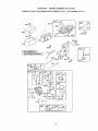
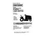
Owner's Manual
l
16.5 HP
ELECTRIC START
42" MOWER
6 SPEED TRANSAXLE
LAWN TRACTOR
Model No.
917.27163!
o Safety
Assembly
o Operation
o Maintenance
Repair Parts
CAUTION:
For answers
Read and follow all Safety
Rules and Instructions before
about this product, Call:
operating this equipment.
Sears Craftsman Help Line
5 am - 5 pro, Mon - Sat
to your questions
1-800-659-5917
Sears, Roebuck and Co., Hoffman Estates, I160179
Visit our Craftsman
website:www.sears_com/craftsman
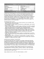
LIMITEDTWOYEARWARRANTYONCRAFTSMANRIDINGEQUIPMENTPARTS
For'two (2) years from the date of purchase,if this CraftsmanRidingEquipmentis
maintained,lubricatedand tuned up accordingto the instructionsin the owner's
manual,Searswill repairor replace,free of charge,any parts found to be defectivein
materialor workmanship°Warrantyserviceis availablefree of charge by returning
your Craftsmanridingequipmentto your nearestSearsServiceCenter.. In-home
warrantyserviceis availablebut a trip chargewill apply.This warrantyappliesonly
while this productis in timeUnited States°
This Warrantydoesnot cover:
• Expendableitems which becomeworn duringnormal use, such as blades, spark
plugs,air cleaners,belts and oil filters..
. Tire replacementor repaircaused by puncturesfrom outside objects,such as nails,
thorns, stumps,or glass.
• Repairsnecessarybecauseof operatorabuse,includingbut not limitedto, damage
caused by towing objectsbeyondthe capabilityof the riding equipment,impacting
objectsthat bend the frame or crankshaft,or over speedingthe engine°
° Repairsnecessarybecauseof operator negligence,includingbut not limitedto,
electricaland mechanicaldamagecaused by improperstorage,failure to use the
propergrade and amountof engineoil, failureto keepthe deck clearof flammable
debris, or the failure to maintainthe equipmentaccordingto the instructions
containedin the owner's manual.
,
Engine (fuel system) cleaning or repairs caused by fuel determined
to be contaminated or oxidized (stale)° In general, fuel sllould be used within thirty (30) days of its
purchase date.
° Riding equipment
used for commercial
or rental purposes. A product is "used for
commercial
purpose" if is .used for any purpose other than single family household
dwellings or in usage where profit is made.
LIMITED
90 DAY WARRANTY
ON BATTERY
For ninety (90) days from date of purchase, if any battery included with this riding
equipment proves defective in material or workmanship
and our testing determines
the battery will not hold a charge, Sears will replace the battery at no charge° Warranty service is available free of charge by returning your Craftsman
riding equipment
to your nearest Sears Service Center. Inohome warranty service is available but a trip
charge will apply. This warranty applies only while this product is in the United States°
TO LOCATE THE NEAREST SEARS SERVICE CENTER OR TO SCHEDULE
IN,HOME WARRANTY
SERVICE, SIMPLY CONTACT SEARS AT 1-800-4-MY-HOME
This Warranty gives you specific legal rights, and you may also have other rights
which may vary from state to state.
Sears,
Roebuck
and Co.
D/817 WA, Hoffman
Estates,
IL 60179
IMPORTANT:This cuttingmachineis capableof amputatingIlands and feet and
throwingobjects_Failureto observe the followingsafetyinstructionscould result in
serious injury or death.
I. GENERAL OPERATION
I!. SLOPE OPERATION
o Read,understand,and follow all
Slopes are a major factor related to loss-ofinstructionsin the manualand on the
control and tipover accidents, which can remachinebeforestarting.
sutt in severe injury or death,
All slopes
o Only allow responsibleadults,who are
require extra caution. If you cannot back up
familiarwith tile instructions,to operate
the slope or if you feel uneasy on it, do not
the machine_
mow it,
° Clearthe areaof objectssuchas rocks, DO:
toys,wire,etco,whichcouldbe picked
° Mow up and down slopes, not across.
up andthrownby the blade°
o Remove obstacles such as rocks, tree
° Be surethe areais clearof otherpeople
limbs, etc.
beforemowing. Stop machineif anyone ° Watch for holes, ruts, or bumps° Uneven
entersthe area..
terrain could overturn the machine° Tall
o Nevercarry passengers.
grass can hide obstacles.
o Do not mow in reverseunlessabsolutely o Use slow speed. Choose a low gear so
necessary.Alwayslookdownand
that you will not have to stop or shift
behindbeforeand w!_ilebacking_
while on the slope_
• Be aware of the mower discharge
direction and do not point it at anyone.
Do not operate the mower without either
the entire grass catcher or the guard in
place°
o Slow down before turning.
o Never leave a running machine
unattended_
Always turn off blades, set
parking brake, stop engine, and remove
keys before dismounting,
o Turn off blades when not mowing.
o Stop engine before removing grass
catcher or unclogging chute.
o Mow only in daylight or good artificial
light.
• Do not operate the machine while under
the influence of alcohol or drugs.
° Watch for traffic when operating near or
crossing roadways..
° Use extra care when loading or unloading the machine into a trailer or truck,.
o Data indicates that operators, age 60
years and above, are involved in a large
percentage of riding mower-related
injuries° These operators should
evaluate their ability to operate the riding
mower safely enough to protect themselves and others frorn serious injury,
o Keep machine free of grass, leaves or
other debris build-up which can touch
hot exhaust / engine parts and burn _ Do
not allow the mower deck to plow leaves
or other debris which can cause build-
• Follow the manufacturer's
recommendations for wheel weights or counterweights to improve stability.
• Use extra care with grass catchers or
other attachments.
These can change
the stability of the machine.
o Keep all movement on the slopes slow
and graduaL Do not make sudden
changes in speed or direction°
• Avoid starting or stopping on a slope. If
tires lose traction,
disengage the blades
and proceed slowly straight down the
slope_
DO NOT:
o Do not turn on slopes unless necessary,
and then, turn slowly and gradually
downhill, if possible.
o Do not mow near drop-offs, ditches, or
embankments.
The mower could
suddenly turn over il a wheel is over the
edge of a cliff or ditch, or if an edge
caves in.
° Do not mow on wet grass. Reduced
traction could cause sliding°
° Do not try to stabilize the machine by
putting your foot on the ground.
o Do not use grass catcher on steep
slopes.
up to occur. Clean any oil or fuel
spillage before operating or storing the
machine.
Allow machine to cool before
storage.
3
HI.CHILDREN
• Never run a machine inside a closed
area.
° Keep nuts and bolts, especially blade
attachment bolts, tight and keep
equipment
in good condition.
° Never tamper with safety devices_
Check their proper operation regularly.
o Keep machine free of grass, leaves, or
other debris build-up. Clean oil or fuel
spillage. Allow machine to cool before
storing,
° Stop and inspect the equipment
if you
strike an object. Repair, if necessary,
before restarting,
o Never make adjustments
or repairs
with the engine running,
o Grass catcher components
are subject
to wear, damage, and deterioration,
which could expose moving parts or
allow objects to be thrown.
Frequently
check components
and replace with
manufacturer's
recommended
parts,
when necessary,
° Mower blades are sharp and can cut.
Wrap the blade(s) or wear gloves, and
use extra caution when servicing them.
o Check brake operation frequently.
Adjust and service as required.
Tragic accidents can occur if the operator
is not alert to the presence of children.
Children are often attracted to the
machine and the mowing activity. Never
assume that children will remain where
you last saw them.
° Keep children out of the mowing area
and under the watchful care of another
responsible
adult.
o Be alert and turn machine off if children
enter time area.
o Before and when backing, look behind
and down for small children.
o Never carry children.
They may fall off
and be seriously injured or interfere
with safe machine operation.
. Never allow children to operate the
machine.
o Use extra care when approaching
blind
corners, shrubs, trees, or other objects
that may obscure vision.
IV, SERVICE
o Use extra care in handling gasoline
and other fuels° They are flammable
and vapors are explosive.
Use only an approved container.
-Never remove gas cap or add fuel
with the engine running° Allow
engine to cool before refueling. Do
not smoke.,
-Never refuel the machine indoors_
- Never store the machine or fuel
container inside where there is an
open flame,
such as a water heater.
• Be sure the area is clear of other
people before mowing. Stop machine
anyone enters the area.
° Never carry passengers or children
even with the blades off.
• Do not mow in reverse unless abso-
° Be alert and turn machine off if children
enter the area.
° Before and when backing, look behind
and down for smatl children.
° Mow up and down slopes (15 ° Max),
not across.
o Remove obstacles such as rocks, tree
limbs, etco
° Watch for holes, ruts, or bumps.
Uneven terrain could overturn the
if
lutely necessary. Always look down
and behind before and while backing.
o Never carry children,, They may fall off
and be seriously injured or interfere
with safe machine operation.
. Keep children out of the mowing area
and under the watchful care of another
responsible
adult.
machine.
4
Tall grass can hide obstacles.
o Use slow speed..Choosea low gear so
thatyou will not haveto stop or shift
while on the slope°
o Avoidstartingor stoppingon a slope.,if
tires losetraction, disengagethe
bladesand proceedslowly straight
down the sloper
o If machinestopswhile going uphill,
disengageblades,shift into reverse
and backdown slowly.
• Do not turn on slopes unless necessary,and then, turn slowly and gradually downhill,if possible..
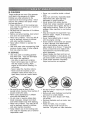
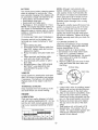
_Look for this symbolto pointout
importantsafetyprecautions.It means
CAUTIQNH!BECOMEALERT!HYOUR
SAFETYISINVOLVED.
_ CAUTION: In orderto prevent
accidentalstartingwhen setting Lip,
transporting,adjustingor making repairs,
always disconnectspark plug wire and
place wirewhere it cannotcontact spark
plug.
_, CAUTION: Do not coast down a hill
in neutral,you may losecontrolof the
tractor°
_, CAUTION: Towonlythe attachments
thatare recommendedby and comply
with specificationsof the manufacturerof
yourtractor.Use commonsensewhen
towing..Operateonly at the lowest
possiblespeed when on a slope° Too
heavyof a load,while on a slope,is
dangerous°Tirescan losetractionwith
the groundand causeyou to lose control
ofyour tractor_
_WARNING: Engineexhaust,some of
its constituents,and certainvehicle
componentscontainor emit chemicals
known to the State of California to cause
cancer and birth defects or other reproductive harrn.
_WARNING:
Battery posts, terminals
and related accessories
contain lead and
lead compounds,
chemicals known to the
State of California to cause cancer and
birth defects or other reproductive
harm.
Wash hands after handling.
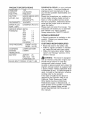
PRODUCT SPECiFICATiONS
GASOLINE
1°25
CAPACITY
UNLEADED
ANDTYPE:
REGULAR
OILTYPE
SAE30 (ABOVE32°F)i
(APFSF- SJ):
SAE5W-30
(BELOW32°F)
OILCAPACITY: 3.0 PINTS
SPARKPLUG: CHAMPIONRC12YC
(GAP: _.030")
GROUNDSPEED(MPH):
FORWARD:
1ST
'1,.1
2ND
3RD
4TH
5TH
6TH
REVERSE:
TIRE
PRESSURE:
instructions
will enable you to assemble
and maintain your tractor properly_,
Always observe the "SAFETY RULES".
1.4
2.2
3.4
4,3
5.4
1.7
REPAIR AGREEMENT
A Repair Agreement
is available on this
product. Contact your nearest Sears
store for details,,
CUSTOMER
FRONT:14 PSI
REAR:
12 PSI
CHARGING
SYSTEM:
HEADLIGHTS
3 AMPS BATTERY
5 AMPS
BATTERY:
AMP/HR:
25
MINoCCA:
190
CASE SIZE:U 1R
BLADE
CONGRATULATIONS
on your purchase
of a new tractorr It has been designed,
engineered
and manufactured
to give
you the best possible dependability
and
performance.
Should you experience
any problem you
cannot easily remedy, please contact a
Sears or other qualified service center°
We have competent, well-trained
technicians and the proper tools to service or
repair this tractor.
Please read and retain this manual. Tile
BOLTTORQIJE:
RESPONSIBiL|TIES
• Read and observe tile safety
,, Follow a regular schedule
in
ing, caring for and using your
° Follow the instructions
under
nance" and "Storage" sections
owner's manual.
rules.
maintaintractor_
"Mainteof this
_,WARNING:
This tractor is equipped
with an internal combustion
engine and
should not be used on or near any
unimproved
forest-covered,
brushcovered or grass-covered
land unless the
engine's exhaust system is equipped with
a spark arrester meeting applicable local
or state laws (if any)If
a spark arrester is
used, it should be maintained
in effective
working order by the operator.
In the state of California the above is
27-35 FT_ LBS
required by law (Section 4442 of the
California Public Resources
Code).
Other states may have similar laws,,
Federal laws apply on federal lands. A
spark arrester for tile muffler is available
through your nearest Sears service
center (See REPAIR PARTS section of
this manuaO.
6
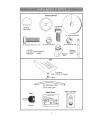
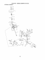
Steering
Wheel
(1) Hex Bolt
318-t6 x 1
Steering
Wheel Insert
(1) Large Fiat Washer
@
(1) Hex Bolt 5/16-1B x t-I/4
.........
_
(1) Locknut 5/16-18
Steering Whee!
......... Adapter
(I) Lockwasher 3/8
Steering
Boot
Extension
Steering
Shaft
Seat
@
_(I)
(1) Washer
17/32 x 1-3/16 x 12 Gauge
Knob
For Future Use
Keys
Slope
Sheet
ll',l
(2) Keys
7
Video
Cassette
©
Your new tractor has been assembled at the factory with exception of tlnose parts left
unassembled
for shipping purposes° To ensure safe and proper operation of your
tractor all parts and hardware you assemble must be tightened securely, Use the
correct tools as necessary to insure proper tightness. Review the video cassette before
you begin.
TOOLS
REQUIRED
FOR ASSEMBLY
A socket wrench set will
easier. Standard wrench
are listed below,,
(1) 9/16"wrench
(2) I/2" wrench
(1) Tire pressure
gauge
_ _---_3t8
'._--_3/8
make assembly
sizes you need
(I) Pliers
(1) Utility
knife
J
_
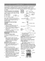
Steering Wheel _
When right or left hand is rnentioned in
this manual, it means when you are in the
operating position (seated behind the
steering wheel)
TO REMOVE TRACTOR
CARTON
UNPACK
Hex
InsertBolt
Lock Washer
...-Steering Boot
Tabs
FROM
Adapter_
Shaft
CARTON
1,
Remove all accessible loose parts
and parts cartons from croton.
2o Cut, from top to bottom, along lines on
all four corner's of carton, and lay
panels flat.
3, Check for any additional loose parts
or cartons and remove.
BEFORE REMOVING
FROM SKID
ATTACH
ASSEMBLE
BOOT
STEERING
5/16 Locknut
Lower
Steering_If_.
Shaft
TRACTOR
.... _.,
5/16 Hex Bolt
_-J"_
'%--',
_
' _"
,"'Y-_I
r
-, __,_
_,-.
- ___. o_.,
_
t €
-,.:..
,,,
-...,:.j.,;,
Tab
Slots
7.
Snap steering wheel insert into center
of steering wheel.
8,, Remove protective materials from
tractor hood and grill.
IMPORTANT:
Check for and remove any
staples in skid that may puncture tires
where tractor is to roll off skid.
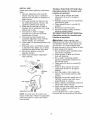
WHEEL
EXTENSION
SHAFT
AND
1. Slide extension shaft onto lower
steering shaft. Align mounting holes
in extension and lower shafts and
install 5/I6 hex bolt and Iocknut.
Tighten securely.
IMPORTANT:
Tighten bolt and nut
securely to 18-22 ft. ibs torque.
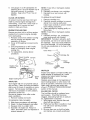
2. Place tabs of steering boot over tab
slots in dash and push down to
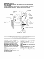
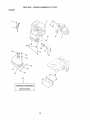
HOW TO SET UP YOUR TRACTOR
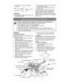
CHECK
1. Lift seat pan to raised position and
open battery box door.
NOTE; If this battery is put into service
after month and year indicated on label
(label located between terminals) charge
battery for minimum of one hour at 6-10
amps. (See "BATTERY" in Maintenance
section of this manual for charging
instructions).
Label
Seat
secure.
INSTALL STEERING WHEEL
3. Position front wheels of the tractor
so
they are pointing straight for_vard.
Remove steering wheel adapter from
steering wheel and slide adapter onto
steering shaft extension.
5. Position steering wheel so cross bars
are horizontal (left to right) and slide
inside boot and onto adapter.
6. Assemble large flat washer, 3/8 lock
washer, 3/8 hex bolt and tighten
securely.
BATTERY
4.
Battery
Box
Terminal
8
Terminal
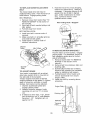
INSTALL
SEAT
Adjust seat before tightening adjustment
knob_
1. Remove adjustment
knob and flat
washer securing seat to cardboard
packing and set aside for assembly of
seat to tractor.
2, Pivot seat upward and remove from
the cardboard packing_ Remove the
cardboard packing and discard,
3. Place seat on seat pan so head of
shoulder bolt is positioned over large
slotted hole in pan.
4, Push down on seat to engage
shoulder bolt in slot and pull seat
towards rear of tractor°
5. Pivot seat and pan forward and
assemble adjustment
knob and flat
washer loosely° Do not tighten°
6_ Lower seat into operating position and
sit in seal
7, Slide seat until a comfortable
position
is reached which allows you to press
clutch/brake
pedal all the way down_
8. Get off seat without moving its
adjusted position.
9. Raise seat and tighten adjustment
knob securely_
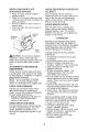
TO ROLL
TRACTOR
Operation
section
function
OFF SKiD
for location
(See
and
of controls)
1, Press lift lever plunger and raise
attachment lift lever to its highest
position,
2_ Release parking brake by depressing
clutch/brake
pedals
3. Place gearshift lever in neutral (N)
position,
4, Roll tractor forward off sldd.
5, Remove banding holding deflector
shield up against tractor,
TO DRIVE TRACTOR
OFF SKID (See
Operation
section
for location
and
function
of controls)
_,WARNING:
Before starting, read,
understand
and follow all instructions
in
the Operation section of this manual.. Be
sure tractor is in a well-ventilated
area°
Be sure the area in front of tractor is clear
of other people and objects°
i_ Be sure all the above assembly steps
have been completed,
2. Check engine oil level and fill fuel
tank with gasoline.
3.. Sit on seat in operating position,
depress clutch!brake
pedal and set
the parking brake..
4_ Place gear shift lever in neutral (N)
position.
5_ Press lift lever plunger and raise
attachment lift lever to its highest
position.
6. Start the engine. After engine has
started, move throttle control to idle
position.
7o Depress clutch/brake
pedal into full
"BRAKE" position and hold. Move
gearshift lever to 1st gear.
8. Slowly release clutch/brake
pedal and
slowly drive tractor off skid.
9. Apply brake to stop tractor, set parking
brake and place gearshift lever in
neutral position.
t 0.Turn ignition key to "OFF" position.
Continue with the instructions
that follow.
Seat
Seat
Bolt
NOTE: You may now roll or drive your
tractor off the slddo Follow the appropriate
instruction below to remove the tractor
from the skid.
9
INSTALL
MULCHER
PLATE
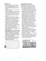
CHECK FOR PROPER
ALL BELTS
(If previously
removed)
i. Raise and hold deflector shield in
upright position°
2, Place front of mulcher plate over front
of mower deck opening and slide into
place, as shown.
3., Hook front latci! into hole on front of
mower deck.
4. Hook rear latch into hole on back of
mower deck_
CHECK
SYSTEM
,/CHECKLIST
BEFORE YOU OPERATE AND ENJOY
YOUR NEW TRACTOR, WE WISH TO
ASSURE THAT YOU RECEIVE THE BEST
PERFORMANCE
AND SATISFACTION
FROM THIS QUALITY PRODUCT,,
PLEASE REVIEW
CHECKLIST:
_CAUTION:
Do not remove deflector
shield from mower. Raise and hold
"TO CONVERT
TO BAGGING
OR
DISCHARGING
Simply remove rnulcher plate and store
in a safe place. Your mower is now ready
for discharging
or installation of optional
grass catcher accessory,
NOTE: It is not necessary to change
blades. The mulcher blades are designed for discharging
and bagging also,
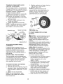
TIRE PRESSURE
The tires on you[ tractor were overinflated at the factory for shipping purposes. Correct tire pressure is important
for best cutting performance,
• Reduce tire pressure to PSI shown in
"PRODUCT SPECIFICATIONS"
section of this manual.
DECK LEVELNESS
For best cutting results, mower tlousing
should be properly leveled.
See "TO
LEVEL MOWER HOUSING" in the
Service and Adjustments
section of this
manual_
THE FOLLOWING
v" All assembly instructions
have been
completed,,
v" No remaining loose parts in carton.
¢" Battery is properly prepared and
charged.
(Minimum
1 hour at 6 amps).
,/Seat is adjusted comfortably
and
tightened
securely,,
v" All tires are properly inflated° (For
shipping purposes, the tires were
overinflated
at the factory).
,/Be sure mower deck is properly leveled
side-to-side/front-to-rear
for best cutting
results. (Tires must be properly inflated
for leveling).
v" Check mower and drive belts. Be sure
they are routed properly around pulleys
and inside all belt keepers.
¢" Check wiring,, See that all connections
are still secure and wires are properly
clamped,,
shield when attaching mulcher plate and
allow it to rest on plate while in operation.
CHECK
BRAKE
After you learn how to operate your
tractor, check to see that tile brake is
properly adjusted.
See "TO ADJUST
BRAKE" in the Service and Adjustments
section of this manual
Latch
Hooks
CHECK
OF
See the figures that are shown for
replacing motion and mower blade drive
belts in the Service and Adjustments
section of this manual, Verify tllat the
belts are routed correctly
Mulcher
Plate
Deflector
Shie
POSITION
WHILE LEARNING HOW TO USE YOUR
TRACTOR, PAY EXTRAATTENTION
TO
THE FOLLOWING
IMPORTANT ITEMS:
v" Engine oil is at proper level.
,/Fuel tank is filled with fresh, clean,
regular unleaded
gasoline.
¢" Become familiar witll all controls - their
location and function_ Operate them
before you start the engine,
,f Be sure brake system is in safe
operating
conditiom
10
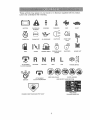
These symbols may appear on your tractor
Learn and understand
their meaning°
BATTERY
CAUTION OR
WARNING
or in literature
REVERSE
supplied
FORWARD
with the product,
SLOW
FAST
GI
ENGINE ON
ENGINE OFF
OIL PRESSURE
LIGHTS ON
OVER TEMP
LIGHT
MOWER HEIGHT
PARKING BRAKE
LOCKED
UNLOCKED
\1
FUEL
CHOKE
AFrACHMENT
CLUTCH ENGAGED
REVERSE
NEUTRAL
H
L
c®) l
HIGH
LOW
PARKING BRAKE
KEEP AREA CLEAR
ATTACHMENT
CLUTCH DISENGAGED
IGNITION
__ ii
MOWER LIFT
SLOPE HAZARDS
(SEE SAFETY RULES SECTION)
=i:::
FREE WHEEL
DANGER, KEEP HANDS AND FEET AWAY
(Automatic Models only)
1I
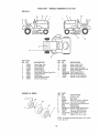
KNOW YOUR TRACTOR
READ THIS OWNER'S
YOUR TRACTOR
MANUAL
AND SAFETY
RULES
BEFORE
OPERATING
Compare tile illustrations
with your tractor to familiarize yourself with the locations
various controls and adjustments.
Save this manual for future reference,
of
Light Switch
Attachment
Clutch
Lever X
Ignition Switch
Lift
Ammeter
" Lever
Plunger
Throttle/Choke
Control
Attachment
Lift Lever
Clutch/Brake
Pedal
Height
Adjustment
Indicator
Parking Brake Lever
Gearshift Lever
Our tractors conform to the safety standards
American National Standards Institute,
AMMETER
- Indicates charging (+) or
discharging
(-) of battery.
ATTACHMENT
CLUTCH LEVER - Used
to engage the mower blades, or other
attachments
mounted to your tractor.
ATTACHMENT
LIFT LEVER - Used to
raise, lower, and adjust the mower deck
or other attachments
mounted to your
tractor.
CLUTCH/BRAKE
PEDAL - Used for
declutching
and braking the tractor and
starting the engine.
GEARSHIFT
LEVER - Selects the speed
and direction of tractor.
of the
IGNITION SWITCH - Used for starting and
stopping the engine.
LIFT LEVER PLUNGER - Used to release
attachment
lift lever wi_en changing its
position.
LIGHT SWITCH -Turns the headlights on
and off.
PARKING BRAKE LEVER - Locks clutch/
brake pedal into the brake position°
THROTTLE/CHOKE
CONTROLUsed
for starting
12
and controlling
engine
speed.
The operation of any tractor can result in foreign objects thrown into
the eyes, which can result in severe eye damage
Always wear safety
glasses or eye shields while operating your tractor or performing any
adjustments
or repairs,
We recommend a wide vision safety mask over
spectacles or standard safety glasses.
HOW TO USE YOUR TRACTOR
TO SET PARKING
IMPORTANT:
Leaving the ignition switch
in any position other than "OFF" will
cause the battery to be discharged,
(dead)°
NOTE: Under certain conditions when
tractor is standing idle with the engine
running, hot engine exhaust gases may
cause "browning" of grass. To eliminate
this possibility, always stop engine when
stopping tractor on grass areas.
,_CAUTION:
Always stop tractor
completely, as described above, before
leaving the operator's position; to empty
grass catcher, etco
TO USE THROTTLE
CONTROL
BRAKE
Your' tractor' is equipped with an operator
presence sensing switch. When engine
is running, any attempt by the operator to
leave the seat without first setting the
parking brake will shut off the engine.
1. Depress clutch/brake
pedal into full
"BRAKE" position and hold.
2. Place parking brake lever in "ENGAGED" position and release
pressure frorn clutch/brake
pedal.
Pedal should remain in "BRAKE"
position°
Make sure parking brake will
hold tractor secure°
Always operate engine at full throttle.
o Operating engine at less than full
throttle reduces the battery charging
rate.
Attachment Clutch Lever
"Engaged" Position
Ignition Key
° Full throttle offers the best bagging
mower performance°
ed"
Th
Choke
Control
Position
Parking Brake
led"
Position
Ciutch/
Brake_
rshift
Lever
"Disengaged"
Position
Position
STOPPING
MOWER
BLADES
o To stop mower blades,move
attachment clutch lever to "DISENGAGED"
position.
GROUND DRIVE o To stop ground drive, depress clutch/
brake pedal into full "BRAKE" position.
• Move gearshift
lever to neutral (N)
position°
ENGINE ° Move throttle control to slow position.
NOTE: Failure to move tllrottle control to
slow position and allowing engine to idle
before stopping may cause engine to
"backfire"°
o Turn ignition key to "OFF" position and
remove key. Always remove key when
leaving tractor to prevent unauthorized
TO MOVE
to stop engine.
AND
BACKWARD
The direction and speed of movernent
is
controlled by the gearshift
lever.
1. Start tractor with clutch/brake
pedal
depressed and gearshift lever in
neutral (N) position..
2_ Move gearshift lever to desired
position.
3o Slowly release clutch/brake
pedal to
start movement
IMPORTANT:
Bring tractor to a complete
stop before shifting or' changing gears.
Failure to do so will shorten the useful life
of your transaxle.
TO ADJUST
MOWER
CUTTING
HEIGHT
The position of the attachment lift lever
determines the cutting height_
o Grasp lift lever.
• Press plunger with thumb and move
lever to desired position.
The cutting height range is approximately 1-1/2 to 4". The heights are
measured from the ground to the blade
tip with the engine not running° These
heights are approximate
and may vary
depending upon soil conditions,
height of
grass and types of grass being mowed.
use.
° Never use choke
FORWARD
and
13
o The average lawn should be cut to
approximately
2-1/2 inches during the
cool season and to over 3 inches
during hot months,, For healthier and
better looking lawns, mow often and
after moderate growthr
° For best cutting perforrnance,
grass
over 6 inches in height should be
mowed twice. Make the first cut
relatively high; tile second
height.
TO OPERATE MOWER
to desired
'{our tractor is equipped with an operator
presence sensing switch. Any attempt by
the operator to leave the seat with the
engine running and the attachment clutch
engaged will shut off tlle engine.
1. Select desired height of cut.
2. Start mower blades by engaging
attachment clutch control,.
TO STOP MOWER BLADES disengage
attachment
clutch control.
_b, CAUTION:
Do not operate the mower
without either the entire grass catcher, on
mowers so equipped, or the deflector
shield in place..
Attachment
Clutch Lever
Attachemnt
"Engaged"
Lever High
Position
_ Position
Low
Position
"Disengaged_
Position
_'1
TO OPERATE
Shield
Deflector
ON HILLS
_CAUTION:
Do not drive up or down
hills with slopes greater than 15 ° and do
not drive across any slope.
. Choose the slowest speed before
starting up or down Mls.
o Avoid stopping or changing speed on
hills.
• If slowing is necessary, move throttle
control lever to slower position.
o if stopping is absolutely necessary,
push clutch/brake
pedal quickly to
brake position and engage parking
brake_
o Move gearshift
lever to 1st gear. Be
sure you have allowed room for tractor
to roll slightly as you restart movement.
o To restart movement,
slowly release
parking brake and clutch/brake
pedal,
• Make alt turns slowly.
TO TRANSPORT
° Raise attachment
lift to highest position
with attachment lift control.
° When pushing or towing your tractor,
be sure gearshift lever is in neutral (N)
position.
o Do not push or tow tractor at more than
five (5) MPHo
NOTE: To protect hood from damage
when transpoiting
your tractor on a truck
or a trailer, be sure hood is closed and
secured to tractor. Use an appropriate
means of tying hood to tractor (rope, cord,
etc.).
TOWING
MENTS
CARTS
AND OTHER
ATTACH-
Tow only the attachments
that are
recommended
by and comply with
specifications
of the manufacturer
of your
tractor° Use common sense when towing.
Too heavy of a load, while on a slope, is
dangerous_ Tires can lose traction with
the ground and cause you to lose control
of your tractor°
BEFORE
CHECK
STARTING
ENGINE
THE ENGINE
OIL. LEVEL
The engine in your tractor has been
sllipped, from the factory, already filled
with summer weight oil.
1o Check engine oil with tractor on level
ground_
2. Remove oil fill cap/dipstick
and wipe
clean, reinsert the dipstick and screw
cap tight, wait for a few seconds,
remove and read oil level
If necessary, add oil until "FULL" mark on
dipstick is reached.
Do not overfill
o For cold weather operation you should
change oil for easier starting (See "OIL
VISCOSITY CHART" in the Maintenance section of this manual),
o To change engine oil, see the Maintenance section in this manual.
14
ADD
GASOLINE
clockwise to "START" position and
release key as soon as engine starts°
Do not run starter continuously
for
more than fifteen seconds per minute.
If the engine does not start after
several attempts, move throttle control
to fast position, wait a few minutes
and try again. If engine still does not
start, move the throttle control back to
the choke position and retry°
o Fill fuel tank_ Use fresh, clean, regular
unleaded gasoline with a minimum of
87 octane.. (Use of leaded gasoline
will increase carbon and lead oxide
deposits and reduce valve life). Do not
mix oil with gasoline.
Purchase fuel in
quantities that can be used within 30
days to assure fuel freshness,
IMPORTANT:
When operating in
temperatures
below 32°F(0°C),
use fresh,
clean winter grade gasoline to tlelp
insure good cold weather starting.
WARM WEATHER STARTING (50 ° F and
above)
6. When engine starts, move the throttle
control to the fast position.
,, The attachments
and ground drive can
now be used if the engine does not
accept the load, restart the engine and
allow it to warm up for one minute
using the choice as described
above.
,_ WARNING:
Experience indicates that
alcohol blended fuels (called gasohol or
using ethanol or methanol) can attract
moisture which leads to separation
and
formation of acids during storage.
Acidic
gas can damage the fuel system of an
engine while in storage.. To avoid engine
problems, the fuet system should be
emptied before storage of 30 days or
longer. Drain the gas tank, start the
engine and let it run until the fuel lines
and carburetor are empty° Use fresh fuel
next season.
See Storage Instructions for
additional information.
Never use engine
or carburetor cleaner products in the fuel
tank or permanent damage may occur..
COLD WEATHER STARTING ( 50" F and
below)
6, When engine starts, allow engine to
run with the throttle control in the
choke position until tile engine runs
roughly, then move throttle control to
fast position. This may require an
engine warm-up period from several
seconds to several minutes, depending on the temperature.
,, The attachments
can also be used
r_. CAUTION:
Fi!l to bottom of gas tank
iller neck° Do not overfill. Wipe off any
spilled oil or fuel. Do not store, spill or
use gasoline near an open flame°
during the engine warm-up period,
NOTE: If at a high altitude (above 3000 feet)
or in cold temperatures (below 32 F) the
carburetor fuel mixture may need to be
adjusted for best engine performance. See
'%0 ADJUST CARBURETOR"
in the Service
TO START ENGINE
When starting the engine for the first time or if
the engine has run out of fuel, it will take extra
cranking time to move fuel from tile tank to
the engine.
1. Sit on seat in operating position,
depress clutch/brake
pedal and set
parking brake_
2. Place gear shift lever in neutral (N)
position.
3o Move attachment clutch to "DISEN_
GAGED" position.
4. Move throttle control to choke position.
NOTE: Before starting, read the warm and
cold starting procedures below_
5. Insert key into ignition and turn key
and Adjustments
15
section of this manual
MOWING
TiPS
o Mower should be properly leveled for
best mowing performance,
See "TO
LEVEL MOWER HOUSING" in the
Service and Adjustments
section of this
manual.
° The left hand side of mower should be
used for trimming,
o Drive so that clippings are discharged
onto the area that has been cut, Have
tile cut area to the right of the tractor.
This will result in a more even distribu_
tion of clippings and more uniform
cutting,.
o When mowing large areas, start by
turning to the right so that clippings will
discharge away from shrubs, fences,
driveways, etc. After one or two
rounds, mow in the opposite direction
making left hand turns until finished.
o If grass is extremely tall, it should be
mowed twice to reduce load and
possible fire hazard from dried clippings. Make first cut relatively high; the
second to the desired height.
o Do not mow grass when it is wet. Wet
grass will plug mower and leave
undesirable
clumps.
Allow grass to dry
before mowing.
° Always operate engine at full throttle
when mowing
to assure better mowing
performance
and proper discharge of
material.
Regulate ground speed by
selecting a low enough gear to give the
mower cutting performance
as well as
the quality of cut desired.
• When operating attachments,
select a
ground speed that will suit the terrain
and give best performance
of the
attachment
being used.
MULCHING
MOWING TIPS
IIVIPORTANT:
For best performance,
keep mower housing free of built-up
grass and trash. Clean after eacfm use°
. The special mulching blade will recut
the grass clippings many times and
reduce them in size so that as they fall
onto the lawn they will disperse into the
grass and not be noticed. Also, the
mulched grass wit! biodegrade
quickly
to provide nutrients for time lawn.
Always mulch witlm your highest engine
(blade) speed as this will provide time
best recutting action of the blades.
• Avoid cutting your lawn when it is wet,
Wet grass tends to form clumps and
interferes with the mulching action.
The best time to mow your lawn is the
early afternoon°
At this time the grass
has dried and the newly cut area will
not be exposed to tile direct sun°
• For best resulls, adjust the mower
cutting height so that the mower cuts off
only the top one-third of the grass
blades. For extremely heavy mulching,
reduce your width of cut on each pass
and mow slowly.
° Certain types of grass and grass
conditions may require that an area be
mulched a second time to completely
hide the clippings.
When doing a
second cut, mow across or perpendicular to the first cut path.
• Change your' cutting pattern from week
to week,, Mow north to south one week
then change to east to west the next
week. This will help prevent matting
and graining of the lawno
f
Max 1/3"
l
lL__
16
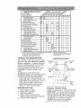
MA,,TE,A,OESO,EOUL,
AS YOU COMPLETE
REGULAR SERVICE
T
/_./_
ERV'C E DATES
chec_
Br.ka
Opo,a,on
V"
it'
.....................
Check Tire Pressure
V'
V'
_Check Operator Presence and ......................
lnledock Systems
tf
R [&eekforLoosa
Fas,ener_
.....................
u_ .....
A i Sharpen!Replace Mower Blades
c
v"
VS
V'4
.............
...............................
v
v ......
0
Check Battery Level
R
CIean Batlery and Teiminals
....
V e
Check Transaxle
V"
Cooling
v'
Adjust Btade Bell(e) Tension
v'o ;;;I;
Adjust Mol.len Drive Bett(s) Tension
Check Engine oil Level
V °
If
Change Engine Oil
E
Clean Air Filter
N
Clean Air Screen
G Insp_Ci
_,_uiiier/spa,k
Arrestor
Replace
Oii'Fi"_';'i"
eq"ippe¢
a
clean
I_tm3
............
V_:_
....................
V'=
_._
....
Engine Cooling Fins
........... , .........
Replace Spark Hug
....
4'eplace
Ai."
Fi"erPaper
ca.,dge
...........................
V';_
_
.....
_'
V%
Reptace Fuel Filler
t - Change m(_.'eo!lan when epe,talfng under a heavy k)ad at tn high ambient leml;,eta.lures
2 - Seraice mo,/e ellen wt;en ,c,pemlieg in dl,rlyat dusly cendilions
3 - II equipped w{lh ell f_ller, change eli every 50 heu{_
5 * If equipped with adj_lslable syelem
e * Net required it equipped with rna_eteeanee,llee ballefy
7 - Tighlan Iienl awle plvc,l boll to 35 II -Ibs maximum
4 _ Replace blades mofe ellen when mewing in sandy sei!
GENERAL
Do not over_tghlen
RECOMMENDATIONS
LUBRICATION
The warranty on this tractor does not cover
items that have been subjected to operator
abuse or negligence.
To receive full value
from the warranty, operator must maintain
tractor as instructed in this manual,
@ S[
Zerk
CHART
Spindle
Zerk
iq7 _
f
Some adjustments will need to be made
periodically to properly maintain your
tractor,
All adjustments in the Service and
Adjustments
section of this manual should
be checked at least once each season.
• Once a year you should replace the
spark plug, clean or' replace air filter, and
check blades and belts for wear. A new
_','Front Wheel ,Bearing
Zerk
Wheel
Beating Zerk
(_Engine /
spark plug and clean air filter assure
proper air4uel mixture and help your
engine run better and last longer.
BEFORE
1_
2,
3o
4_
5.
EACH
USE
Check engine oil level.
Check brake operation.
Check tire pressure.
Check operator presence and
interlock systems for proper' operation.
Check for loose fasteners,
([JSAE
30 or 10w30
MOTOR
OIL
@GENERAL PURPOSE GREASE
_,REFER TO Maintenance "ENGINE" SECTION
17
IMPORTANT.'
Do not oil or grease the pivot
points which have special nylon bearings,
Viscous lubricants will attract dust and dirt
that will shorten the life of the self-lubricating bearings.
If you feel they must be
lubricated, use only a dry, powdered
graphite type lubricant sparingly.
TRACTOR
Alwaysobservesafety ruleswhen
performingany maintenance.
BRAKE OPERATION
If tractorrequiresmorethan six (6) feet
stoppingdistanceat high speed in
highestgear,then brakemustbe adjusted.(See"TOADJUSTBRAKE"in the
ServiceandAdjustmentssectionof this
manual).
TIRES
° Maintainproper air pressurehi all tires
(See"PRODUCTSPECIFICATIONS"
sectionof this manual).
o Keeptires free of gasoline,oil, or insect
controlchemicalswhich can harm
rubber.
o Avoid stumps,stones,deep ruts, sharp
objectsand other hazardsthat may
causetire damage.
NOTE:Toseal tire puncturesand prevent
flat tires due to slowleaks,tire sealant
may be pu[chasedfrom your local parts
dealer.Tire sealantalso preventstire dry
rot and corrosion.
OPERATORPRESENCESYSTEM
Be sure operator presenceand interlock
systemsare workingproperly. If your
tractordoesnot functionas described,
repair the problemimmediately.
o The engineshouldnot start unlessthe
brake pedal is fully depressedand
attachementclutchcontrolis in the
disengaged position.
o Whenthe engineis running,any
attemptby the operatorto leavethe
seat withoutfirst settingthe parking
brakeshouldshut off the engine.
o Whenthe engineis runningand the
attachmentclutch is engaged,any
attemptby the operatorto leavethe
seat should shut off the engine.
o The attachmentclutch should never
operateunlessthe operatoris in the
seat.
BLADE CARE
Forbest resultsmowerbladesmust be
kept sharp. Replacebentor damaged
blades°
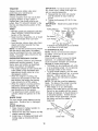
BLADE REMOVAL
1. Raise mowerto highestpositionto
allow accessto blades.
2. Removehex bolt, lockwasherand flat
washer securing blade°
3.. Installnew or resharpenedblade with
trailingedge up towardsdeck as
shown.
IMPORTANT:Toensureproperassembly, centerhote in blade mustalign with
star on mandrelassembly.
4. Reassemblehex bolt, lock washer
andflat washer in exact order as
shown.
Tighten bolt securely (27-35 Fto Lbs.
torque).
Ir,4PORTANT:
Blade bolt is grade 8 heat
treated°
5,
Trailing Edge Up
Blade
Mandr'el Assembly
Center
Hole
Fiat Washer....
Lock Washer
%
_--Hex
Bolt (Grade)
*A Grade 8 heat treated bolt can be identified
by six lines on the bolt head.
TO SHARPEN
BLADE
NOTE: We do not recommend sharpening blade - but if you do, be sure the
blade is balanced.
Care should be taken to keep the blade
balanced.
An unbalanced
blade will
cause excessive vibration and eventual
damage to mower and engine.
o The blade can be sharpened with a file
or on a grinding wheel, Do not attempt
to sharpen while on time mower.
o To check blade balance, you will need
a 5/8" diameter steel bolt, pin, or a cone
balancer.
(When using a cone balancer, follow tile instructions
supplied
with balancer.)
NOTE: Do not use a nail for balancing
blade, The lobes of the center hole may
appear to be centered, but are not,
° Slide blade on to an unthreaded
portion of the steel bolt or pin and hold
the bolt or pin parallel with the ground.
If blade is balanced, it should remain in
a horizontal position.
If either end of
the blade moves downward,
sharpen
the heavy end until the blade is
balanced_
Center Hole
18
"_
BATTERY
Your tractor has a battery charging systern
which is sufficient for normal use° However; periodic charging of the battery with
an automotive
charger will extend its life.
. Keep battery and terminals clean_
o Keep battery bolts tight°
. Keep small vent holes open.
o Recharge at 6-t0 amperes for I hour,,
NOTE: The original equipment battery on
your tractor is maintenance
freer Do not
attempt to open or remove caps or covers.
Adding or checking level of electrolyte is
not necessary.,
TO CLEAN
BATTERY
NOTE: Altllough multi-viscosity
oils
(5W30, t0W30 etco) improve starting in
cold weather, these multi-viscosity
oils
will result in increased oil consumption
when used above 32°R Check your engine oil level more frequently
to avoid
possible engine damage from running
low on oil.
Change the oil after every 25 hours of op*
eration or at least once a year if the tractor is not used for 25 hours in one year,
Check the crankcase
oil level before
starting the engine and after each eight
(8) hours of operation. Tighten oil fill cap/
dipstick securely each time you check the
oil level.
AND TERMINALS
Corrosion and dirt on the batter,/and
terminals can cause the battery to "leak"
power.
Io Open battery box door,
2. Disconnect BLACK battery cable first
then RED battery cable and remove
batter/from
tractor.
3, Rinse the battery with plain water and
dry.
4. Clean terminals and battery cable
ends with wire brush until bright.
5, Coat terminals with grease or petroleum jelly,
6. Reinstall batter/(See
"REPLACING
BATTERY"
in the SERVICE AND
ADJUSTMENTS
section of this
manual).
TO CHANGE
the fitting.
Oil Drain 'valve
Closed
and
Locked
Position
Check V-belts for deterioration
and wear
after 100 hours of operation and replace
if necessary° The belts are not adjustable.
Replace belts if they begin to slip from
wear,,
COOLING
3.
4o
5.
ENGINE
LUBRICATION
Only use high quality detergent oil rated
with API service classification
SF - SJ. Select the oil's SAE viscosity grade according to your expected operating temperature.
c
_o
._0
TEMPERATURE
6_
7.
SAEV,SCOSf_
G'RADES
-to
o
_o
_o
_o
Drain Tube
Yellow
Cap
Keep transaxte free from build-up of dirt
and chaff which can restrict cooling.
..................
OIL
Determine temperature
range expected
before oil change,
All oil must meet API
service classification
SF-SJ.
o Be sure tractor is on level surface.
, Oil will drain more freely when warm
o Catch oil in a suitable container°
1, Remove oil fill cap/dipstick.
Be careful
not to allow dirt to enter the engine
when changing oil.
2. Remove yellow cap from end of drain
valve and install the drain tube onto
V-BELTS
TRANSAXLE
ENGINE
4o
RANGE ANTIOIPATEO BEFORE NF.,XTOI,,L,,CHANGE
!9
Unlock drain valve by pushing inward
slightly and turning counterclockwise.
To open, pull out on the drain valve.
After' oil has drained completely, close
and lock the drain valve by pushing
inward and turning clockwise until the
pin is in the locked position as shown.
Remove the drain tube and replace
the cap onto to the end of the drain
valve,
Refill engine with oil through oil fill
dipstick tube_ Pour slowly. Do not
overfill. For approximate
capacity see
"PRODUCT SPECIFICATIONS"
section of this manual.
Use gauge on oil fill cap/dipstick
for
chectdng level. Be sure dipstick cap is
tightened securely for accurate
reading_ Keep oil at "FULL" line on
dipstick,
B,
CLEAN
COOLING
FINS
Remove any dust, dirt or' oil from engine
cooling fins to prevent engine damage
from overheating.
1. Remove screws from blower housing
and lift housing and dipstick tube
assembly off engine_
2_ Cover oil fil! opening to prevent entry
of dirt,
3.
4.
knob(s).
TO SERVICE
AIR SCREEN
Air screen must be kept free of dirt and
chaff to prevent engine damage from
overheating.
Clean with a wire brush or
compressed
air to remove dirt and
stubborn dried gum fibers°
ENGINE
NOTE: tf very dirty or damaged,
replace
pre-cteaner.
6. Reinstall pre-cleaner
over cartridge°
7. Reinstall cover and secure with
Use compressed
air or stiff bristle
brush to thoroughly
clean engine
cooling fins.
To reassemble,
reverse above
procedure_
CARTRIDGE
1 Remove cartridge nut,
2. Carefully remove cartridge to prevent
debris frorn entering carburetor.
Clean base carefully to prevent debris
from entering carburetor.
3 Clean cartridge by tapping gently on
flat surface.
NOTE: If very dirty or damaged, replace
cartridge.
4. Reinstall car[ridge, nut, precleaner,
cover and secure with knob(s).
IMPORTANT:
Petroleum solvents, such
as kerosene, are not to be used to clean
the cartridge.
They may cause deterioration of the cartridge r Do not oil cartridge.
Do not use pressurized
air to clean or dry
cartridge.
Cover Knob
Cover@Cartridge
Screws
Blower Housing
Paper
Foam
Pre-Cleaner
Dipstick Tube
Assembly
Nut
Screws
1.-,_-..
Cartridge
Air Screen
_'_
Base
MUFFLER
Engine Cooling Fins
)ark
Plug
AIR FILTER
Your engine will not run properly using a
dirty air' filter, Clean the foam pre-cleaner
after every 25 hours of operation or every
season.
Service paper cartridge every
100 hours of operation or every season,
whiclqever occurs first.
Service air cleaner more often under
dusty conditions°
I, Remove knob(s) and cover,
TO SERVICE
2.
&
4.
5.
PRE-CLEANER
Slide foam pre-cleaner
off cartridge.
Wash it in liquid detergent and water.
Squeeze it dry in a clean cloth.
Saturate it in engine oil. Wrap it in
clean, absorbent
cloth and squeeze to
remove excess oil,
inspect and replace corroded muffler and
spark arrester (if equipped) as it could
create a fire hazard and/or damage,
SPARK PLUGS
Replace spark plugs at the beginning of
each mowing season or after every 100
hours of operation, whichever occurs first.
Spark plug type and gap setting are
shown in "PRODUCT
SPECIFICATIONS"
section of this manual,
IN-LINE
FUEL FILTER
The fuel filter should be replaced once
each season_ tf fuel filter becomes
clogged, obstructing
fuel flow to carburetor, replacement
is require&
t. With engine cool, remove filter and
plug fuel line sections.
2o Place new fuel filter in position in fuel
line with arrow pointing towards
carburetor.
3_
Be sure there are no fuel line leaks
and clamps are properly positioned.
2O
o Keepfinishedsurfacesand wheelsfree
of all gasoline,oil, etc.
o Protectpain[edsurfaceswith automotive type wax°
We do not recommendusing a garden
hoseto cleanyour tractorunlessthe
electricalsystem,muffler,air filter and
carburetorare coveredto keepwater out.
Water in enginecan result in a shortened
engine life.
4. Immediatelywipe up any spilled
gasoline.
Clamp__--_-_
FuelFilter----_.__-L__.,'
Clamp
CLEANING
,, Cleanengine,battery,seat,finish,etc.
of all foreignmatter.,
CAUTION: BEFOREPERFORMINGANY SERVICEORADJUSTMENTS:
1_Depressclutch/brakepedalfully and set parkingbrake.
2. Placegearshiftleverin neutral(N) position°
3oPlaceattachmentclutch in "DISENGAGED"position.
4oTurn ignitionkey "OFF"andremovekey.
5. Makesure the bladesand all movingparts havecompletelystopped.
6. Disconnectspark plug wire from spark plug and place wire where it cannot
come in contactwith plug,.
TRACTOR
9.
TO REMOVE
Raise lift lever to raise suspension
arms_ Slide mower out from under
tractor.,
IMPORTANT:
If an attachment other than
the mower deck is to be mounted on the
tractor, remove the front links and hook
the clutch spring Into square hole in
frame.
TO INSTALL MOWER
Io Raise attachment
lift lever to its
MOWER
Mower will be easier to remove from the
right side of tractor.
1, Place attachrnent
clutch in "DISENGAGED" position,,
2. Move attachment
lift lever forward to
lower mower to its lowest position,
3, Roll belt off engine pulley,
4, Remove small retainer spring, and lift
clutch spring off pulley bolto
5, Remove large retainer spring, slide
collar off and push housing guide out
of bracket,
6.
7.
8.
highest position.
Slide mower under tractor with
deflector shietd to right side of tractor,
3o Lower lift lever to its lowest position.
4, Install mower in reverse order of
removal instructions,,
2,
Disconnect anti-swaybar
from chassis
bracket by removing retainer spring.
Disconnect suspension
arms from
rear deck brackets by removing
retainer' springs.
Disconnect front links from deck by
removing retainer' springs.
Small Retainer Spring
fJ
Suspension Arms
.S_:_Z.
",,
-_- -i
° :-i" , ._--1-._._ Square Hole
Engine Pulley
Clutch S
Link
Retainer Spring
Anti-Sway
Retainer Springs
(Both Sides)
Collar..,
Housing Guide
Bra
Large Retainer Spring
21
TO LEVEL
MOWER
HOUSING
Adjust tile mower while tractor is parked
on level ground or driveway.
Make sure
tires are properly inflated (See "PRODUCT SPECIFICATIONS"
section of this
manual).
If tires are over or
underinflated,
you will not properly
adjust your mower.
SIDE-TO-SIDE
ADJUSTMENT
,, Raise mower to its highest position.
o At tl_e midpoint of both sides of mower,
measure height from bottom edge of
mower to ground.
Distance "A" on
both sides of mower should be the
same or within 1/4" of each other.
o If adjustment
is necessary, make
adjustment
on one side of mower onlyo
• To raise one side of mower, tighten lift
link adjustment nut on that side.
. To lower one side of mower, loosen lift
link adjustment nut on that side°
NOTE:
Each full turn of adjustment nut
will change mower height about I/8".
. Recheck measurements
after adjusF
ing.,
Bottom edge of
mower to ___
°°
• Before malting any necessary adjustments, check that both front links are
equal in length.
• If links are not equal in length, adjust
one link to same length as other link,
• To lower front of mower loosen nut "E"
on both front links an equal number of
turns°
o When distance "D" is 1/8" to 1/2" lower
at front than rear, tighten nuts "F"
against trunnion on both front links.
,, To raise front of mower, loosen nut "F"
from trunnion on both front links,
Tighten nut "E" on both front links an
equal number of turns.
• When distance "D" is 1/8" to 1/2" lower
at front than rear, tighten nut "F"
against trunnion on both front links_
• Recheck side-to-side
adjustmenL
_o\_x
,.
o o__
Mandrel
Bottom edge of
mower to
Both Front kinks Should be Equal in Length
Lq eT T
JA
n Arm
l= ....
Lift Link
Adjustment
FRONT-TO-BACK
ADJUSTMENT
IMPORTANT:
Deck must be level side-to
side. if the following front-to-back
adjustment
is necessary, be sure to
adjust both front links equally so mower
wilt stay level side-to-side.
To obtain the best cutting resuits, the
mower housing should be adjusted so
that the front is approximately
1/8" to 1/2"
lower tllan the rear when the mower is in
its highest position.
Check adjustment on right side of tractor.
Measure distance "D" directly in front
and behind the mandrel at bottom edge
of mower housing as shown.
,:E r,
Nut
Front Links
TO REPLACE
BELT
MOWER
BLADE
DRIVE
The mower blade drive belt may be
replaced without tools_ Park the tractor
level surface
Engage parking brake,
44
on
BELT REMOVALRemove mower from tractor (See "TO
REMOVE MOWER" in this section of
this manual),
2,, Work belt off both mandrel pulleys and
idler pulleys,
3, Pull belt away from mower_
Road test tractor for proper stopping
distance as stated above,
Readjust if
necessary.
If stopping distance is still
greater than six (6) feet in highest
gear, further maintenance
is necessary, Contact a Sears or other
qualified service center.
I.
With Parking
Brake "Engaged"
BELT INSTALLATION
4. Install new belt in reverse order of
removal,
5o Make sure belt is in all pulley grooves
and inside all belt guides,,
6, Install mower in reverse order of
removal instructions,
Nut "A"
Nut
Mandrel
-_]_
OperaA_
m ting
Idler'
TO REPLACE
BRAKE
Your tractor is equipped with an adjustable brake system which is mounted on
the right side of the transaxle.
If tractor requires more than six (6) feet
stopping distance at high speed in higtlest
gear on a level dry concrete or paved
surface, then brake must be adjusted.
1. Depress clutch/brake
pedal and
engage parking brake
2, Measure distance between brake
3,
DRIVE
BELT
Park the tractor on level surface_ Engage
parking brake, For assistance, there is a
belt installation guide decal on bottom
side of left footresL
1. Remove mower (See "TO REMOVE
MOWER" in this section of this
manual.)
2, Remove belt from stationary idler and
clutching idler_
3. Pull belt slack toward rear of tractor.
Remove belt upwards from transaxle
pulley by deflecting belt keepers.
4, Pull belt toward front of tractor and
remove downwards
from around
engine pulley°
5. Install new belt by reversing above
procedure.
Mandrel
Pulley
TO ADJUST
MOTION
Engine
operating arm and nut "A" on brake
rod.
If distance is other than t-1/2", loosen
jam nut and turn nut "A" until distance
becomes 1-1/2". Retighten jam nut
against nut "A"o
Clutching
Stationary Idler
Transaxle
Pulle
23
TRANSAXLE
GEAR SHIFT LEVER
NEUTRAL
ADJUSTMENT
The transaxle should be in neutral when
4+ Replace washers and snap retaining
ring securely in axle groove.
5+ Replace axle cover.
NOTE: To seal tire punctures and
prevent flat tires due to slow leaks, tire
sealant may be purchased from your
local parts dealer, Tire sealant also
prevents tire dry rot and corrosion,.
the gear shift lever is in neutral (N) (lock
gate) position, The adjustment is preset at
the factory; however, if adjustment
is
needed, proceed as follows:
1. Make sure transaxle is in neutral (N).
NOTE: When the tractor rear wheels
move freely, the transaxle is in neutral.
2+ Loosen adjustment
bolt in front of the
right rear wheel.
3. Position the gear shift lever in the
neutral (N) position.
4, Tighten adjustment
bolt securely.
NOTE: If additional clearance is needed
Washers
Retaining
Ring
Axle
Cover
to get to adjustment
bolt, move mower
deck height to the lowest position+
Gearshift
Lever
Square Key
(Rear Wheel Only)
Neutral Lock Gate
TO START
BATTERY
ENGINE
WITH A WEAK
,_,CAUTION:
Lead-acid batteries generate
explosive gases. Keep sparks, flame and
smoking materials away from batteries.
Always wear eye protection when around
batteries.
Adjustment Bolt
TO ADJUST
ALIGNMENT
STEERING
If your battery is too weak to start the engine, it
should be recharged. (See "BATTERY" in the
MAINTENANCE section of this manual)°
If "jumper cables" are used for emergency
starting, follow this procedure:
IMPORTANT: Your tractor is equipped with a
12 volt negative grounded system. The other
vehicle must also be a 12 volt negative
grounded system+ Do not use your tractor'
battery to start other vehicles.
WHEEL
If steering wheel crossbars are not
horizontal (left to right) when wiqeels are
positioned
straight forward, remove
steering wheel and reassemble
per
instructions in the Assembly section of
this manual+
FRONT WHEEL TOE-INIOAMBER
TO ATTACH JUMPER CABLES -
The front wheel toeqn and camber are
not adjustable on your tractor+ If damage
has occurred to affect the front wheel
toe-in or camber, contact a Sears or
other qualified service center.
TO REMOVE
WHEEL
I+ Connect each end of the RED cable to
the POSITIVE (+) terminal of each
battery, taking care not to short
against chassis+
2. Connect one end of the BLACK cable
to the NEGATIVE (-) terminal of fully
charged battery,
3. Connect the other end of the BLACK
cable to good CHASSlS GROUND,
away from fuel tank and battery.
FOR REPAIRS
1_ Block up axle securely.
2. Remove axle cover, retaining ring and
washers to allow wheel removal (rear
wheel contains a square key + Do not
lose).
3o Repair tire and reassemble,
NOTE: On rear wheels only: align
grooves in rear wheel hub and axle.
Insert square key.
TO REMOVE CABLES, REVERSE ORDER 1+ BLACK cable first from chassis and
then from the fully charged battery,+
2. RED cable last from both batteries.
24
Positive Terminal
Ke
Nut
Negative Terminal
Hex
Bolt
Positive (Red) Cable
TO REPLACE
Cables
REPLACING
HEADLIGHT
BULB
1. Raise hood.
2. Pull bulb holder out of the hole in the
backside of the grill,
3. Replace bulb in holder and push bulb
holder securely back into the hole in
the backside of the grill.
4. Close hood,,
INTERLOCKS
AND RELAYS
Charged
Battery
Positive Terminal
Negative (Black)
Cable
Negative Terminal
BATTERY
Loose or damaged wiring may cause your
tractor to run poorly, stop running, or
prevent it from starting.
,, Check wiring.
See electrical wiring
diagram in the Repair Parts section.
TO REPLACE
FUSE
_CAUTION:
Do not short battery
terminals by allowing a wrench or any
other object to contact both terminals at
the same time. Before connecting batten7,
remove metal bracelets, wristwatch
bands, rings, etco
Positive terminal must be connected first
to prevent sparking from accidental
grounding
1. Lift seat pan to raised position and
open battery box door.
2o Disconnect BLACK battery cable first
then RED battery cable and carefully
remove battery from tractor.
3, Install new battery with terminals in
same position as old battery.
4. First connect RED baltery cable to
positive (+) terminal with hex bolt and
keps nut as shown. Tighten securely_
5. Connect BLACK grounding cable to
negative (-) terminal with remaining
hex bolt and keps nut. Tighten
securely,,
6o Close battery box door.
Replace with 20 amp automotive4ype
plug-in fuse. The fuse holder is located
behind the dash,
TO REIVtOVE HOOD AND GRILL
ASSEMBLY
1, Raise hood.
2. Unsnap headlight wire connector.
3. Stand in front of tractor_ Grasp hood at
sides, tilt toward engine and lift off of
tractor.
4_ To replace, reverse above procedure.
jjHood
.%,.
/
/
Seat
Battery
Door
Be;
25
_'\.
Headlight
C_
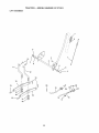
Connector
Wire
ENGINE
Maintenance, repair, or replacement of the
emission control devices and systems, which
are being done at the customers expense,
may be performed by any non-road engine
repair establishment or individual, Warranty
repairs must be performed by an authorized
engine manufacturer's service outlet.
TO ADJUST THROTTLE
CONTROL
CABLE
The throttle control has been preset at the
factory and adjustment should not be
necessary. Check adjustment as described
below before loosening cable. If adjustment
is necessary, proceed as follows:
1. With engine not running, rnove throttle
control lever from slow to choke position_
Slowly move lever from choke to fast
position,
2. Check that holes "A" in governor control
lever and hole in governor plate line-up.
if holes "A" are not aligned, loosen clamp
screw and move throttle cable until holes
are aligned°
securely.
PRELIMINARY
Governor
, ---._ Contro_lLe(_
ver
J_'_ 1/'i_C°ntr°' P,ate
Holes 'W' "_ "__il.@J
_'e' _v
_ "_....
t hrottle
Cable
CARBURETOR
NOTE: The carburetor on this engine is low
emission. It is equipped with an idle fuel
adjusting needle with a lirniter cap, which
allows some adjustment within the limits
allowed by the cap. Do not attempt to remove
the limiter cap. The limiter cap cannot be
removed without breaking the adjusting
needle.
The carburetor has been preset at the factory
and adjustment should not be necessary°
However, minor adjustment may be required
to compensate for differences in fuel,
temperature, altitude or load. If the carburetor
does need adjustment, proceed as follows:
in general, turning idle mixture valve in
(clockwise) decreases the supply of fuel to
the engine giving a leaner fuel/air mixture.
Turning the idle mixture valve out (counter-.
clockwise) increases the supply of fue! to the
engine giving a richer fuel!air mixture
SETTING
1o Air cleaner assembly must be assembled
to the carburetor when making carburetor
adjustments.
2. Be sure the throttle control cable is
adjusted properly (see above),
FINAL SETTING t.
2,
Start engine and allow to warm for five
minutes. Make final adjustments with
engine running and shiflJmotion control
lever in neutral (N) position.
Move throttle control lever to slow
position° With finger, rotate and hold
throtIle lever against idle speed screw_
Turn idle speed screw to attain 1750
RPM,
3_ While still holding throttle lever against
idle speed screw, turn idle mixture valve
full travel clockwise then counterclockwise until engine runs rough. Turn valve
to a point midway between those two
positions. Release throttle lever
Tighten clamp screw
Governor
TO ADJUST
IMPORTANT: Damage to the needle valve
and the seat in carburetor may resutt if screw
is turned in too tight.
ACCELERATIONTEST
4_ Move throttle control lever from slow to
fast position, if engine hesitates or dies,
rum idle mixture valve out (counterclockwise) 1/8 turn. Repeat test and continue
to adjust, if necessary, until engine
accelerates smoothly,
High speed stop is factory adjusted, Do not
adjust - damage may resulL
IMPORTANT: Never tamper with the engine
governor, which is factory set for proper
engine speed. Overspeeding the engine
above the factory high speed setting can be
dangerous, if you think the engine-governed
high speed needs adjusting, contact a
Sears or other qualified service center,
which has proper equipment and experience
to make any necessary adjustments.
IdLeSpeed
F
Screw----'--
L
C
Idle
With Limiter
26
Immediately prepare your tractor for
storage at the end of the season or if the
tractor wil! not be used for 30 days or
more.
with gasoline in the tank inside a building
where fumes may reach an open flame or
spark. Allow the engine to cool before
storing in any enclosure°
hose, or tank during storage° Also,
experiance
indicates that alcohol
blended fuels (called gasohol or using
ethanol or methanol) can attract moisture
which leads to separation
and formation
of acids during storage. Acidic gas can
damage the fuel system of and engine
while in storage.
1_ Drain the fuel tank_
TRACTOR
2.
CAUTION:
Never store the tractor
Start the engine and let it run until the
fuel lines and carbureto_ are empty.
• Never use engine or carburetor
cleaner
products in the fuel tank or permanent
damage may occur°
o Use fresh fuel next season,
Remove mower from tractor for winter
storage,
When mower is to be stored for
a period of time, clean it thoroughly,
remove all dirt, grease, leaves, etc. Store
in a clean, dry area.
1, Clean entire tractor (See "CLEANING"
in the Maintenance
section of this
manual).
2. Inspect and replace belts, if necessary
(See belt replacement
instructions
in
the Service and Adjustments
section
of this manual).
3 Lubricate as shown in the Maintenance section of this manual.
4. Be sure that all nuts, bolts and screws
are securely fastened,
Inspect moving
parts for damage, breakage and wear.
Replace if necessary,
5. Touch up all rusted or chipped paint
surfaces; sand lightly before painting.
NOTE:
Fuel stabilizer is an acceptable
alternative in minimizing
the formation of
fuel gum deposits during storage° Add
stabilizer to gasoline in fuel tank or
storage container.
Always follow the mix
ratio found on stabilizer container.
Run
engine at least 10 minutes after adding
stabilizer to allow tile stabilizer to reach
the carburetor_
Do not drain the gas tank
and carburetor if using fuel stabilizer.
ENGINE OIL
Drain oil (with engine warm) and replace
with clean engine oil.. (See "ENGINE" in
the Maintenance
section of this manual).
CYLINDER(S)
1_ Remove spark plug(s).
2. Pour one ounce of oil through spark
plug hole(s) into cylinder(s).
3. Turn ignition key to "START" position
for a few seconds to distribute oil,
BATTERY
o Fully charge the battery for storage°
o After a period of time in storage, battery
may require recharging..
o To help prevent corrosion and power
leakage during long periods of storage,
batten./cables
should be disconnected
and battery cleaned thoroughly
(see
"TO CLEAN BATTERY AND TERMINALS" in the Maintenance
section of
4,, Replace
with new spark plug(s)o
OTHER
o Do not store gasoline from one season
to another,
° Replace your gasoline can if your can
starts to rust° Rust and/or dirt in your
gasoline will cause problems.
. If possible, store your tractor indoors
and cover it to give protection from dust
and dirt
o Cover your' tractor with a suitable
protective cover' that does not retain
moisture.
Do not use plastic. Plastic
cannot breathe which allows condensation to form and will cause your
tractor to rust,,
IMPORTANT:
Never cover tractor while
engine and exhaust areas are still warm°
this manual).
,, After cleaning, leave cables disconnected and place cables where they
cannot come in contact with battery
terminals.
o If battery is removed from tractor for
storage, do not store battery directly on
concrete or damp surfaces°
ENGINE
FUEL SYSTEM
IMPORTANT:
It is important to prevent
gum deposites from forming in essential
fuel system parts such as carburetor, fuel
27
TROUBLESHOOTING
CHART
PROBLEM
CAUSE
Will not start
CORRECTION
1. Out of fue!.
2.
Engine not "CHOKED"
properly.
3. Engine flooded°
4.
5.
6,
7
10. Engine valves out of
adjustment.
t, Dirty air filter_
2. Bad spark plug.
3. Weak or dead battery°
4_ Dirty fuel filter.
5. Stale or dirty fuel.
6 Loose or damaged wiring,
7. Carburetor
out of adjustment°
8.
Enginewi!l
turn over
not
Engine clicks
will not start
but
Engine valves
adjustment°
Fill fuel tank.
See "TO START ENGINE"
in Operation section.
3. Wait several minutes
before attempting to start.
4. Replace spark plug.
5. Clean/replace
air filter.
6. Replace fuel filter.
7. Drain fuel tank and
carburetor, refill tank with
fresh gasoline and replace
fuel filter,
Bad spark plug,
Dirty air filter,
Dirty fuel filter,
Waterin
fuel.
8. Loose or damaged wiring.
9. Carburetor
out of adjustment.
Hard to start
I.
2.
out of
8. Check all wiring.
9o See "To Adjust Carburetor"
in Service Adjustments
section.
10.Contact
a Sears or other
qualified service center.
1. Clean/replace
air filter.
2. Replace spark plug,
3,, Recharge or replace
battery_
4o Replace fuel filter,
5, Drain fuel tank and refill
with fresh gasoline,
6. Check all wMng.
7_ See "To Adjust Carbureto¢'
in Service Adjustments
section.
8. Contact a Sears or other
qualified service center,
1, Clutch/brake
pedal not
depressed.
2_ Attachment
clutch is
engaged.
3. Weak or dead battery,,
2.
4_
5.
6
7.
4,,
5o
6,
7_
Blown fuse.
Corroded battery terminals.
Loose or damaged wiring.
Faulty ignition switch.
1,
3.
8. Faulty solenoid
or starter_
8.
9o Faulty operator
switch(es)_
presence
9.
1.
2.
3.
4.
Depress clutch/brake
pedal,
Disengage
attachment
clutch.
Recharge or replace
battery,
Replace fuse.
Clean battery terminals.
Check all wMng.
Check/replace
ignition
switch.
ChecWreptace
solenoid or
starter:
Contact a Sears or other
qualified
Weak or dead battery.
Corroded battery terminals.
Loose or damaged wiring.
Faulty solenoid or starter.
28
I.
2.
3.
4,
service
center°
Recharge or replace battery.
Clean battery terminals.
Check all wiring.
Chectdreplace
solenoid or
starter,,
TROUBLESHOOTING
PROBLEM
Loss of power
CHART
CORRECTION
CAUSE
1,, Cutting too much grass/too
fast.
2. Throttle in "CHOKE"
position_
3. Build-up of grass, leaves
and trash under mower,
4. Dirty air filter.
5, Low oil level/dirty oilo
6. Faulty spark plugo
7.
8,
Dirty fuel filter.
Stale or dirty fuel.
9_ Water in fuel.
t0oSpark
plug wire loose.
11 .,Dirty engine air screen/fins,
I2. Dirty/clogged
muffler.
13. Loose or damaged wiring.
14.Carburetor
out of
adjustment.
15. Engine valves
adjustmenL
Excessive
vibration
I.
Worn,
2.
Bent blade mandrel.
3.
Looseldamaged
Engine continues
to run
when operator
leaves seat with
with attachment
clutch engaged
Poor cut - uneven
out of
,
t.
bent or loose blade,,
part(s),
I.
Set in "Higher Cut" position/
reduce speed°
2, Adjust throttle control.
3.
1.
2.
3,
1,
Worn,
Io
2o Mower deck not level,
3. Buildup of grass, leaves,
and trash under mower°
4o Bent blade mandrel.
5. Clogged mower deck vent
holes from buildup of
grass, leaves, and trash
around mandrels.
29
underside
of mower
housing.
4. Clean/replace
air filter.
5. Check oil level/change
oil,
6. Clean and regap or' change
spark plug.
7o Replace fuel filter.
8. Drain fuel tank and refill with
fresh gasoline.
9o Drain fuel tank and carbure
tot, refill tank with fresh
gasoline and replace fuel
filter°
10oConnect and tighten spark
plug wirer
t I ,Clean engine air screenifins_
12.Clean/replace
muffler.
13.Check
al! wiring,
14. See "To Adjust Carburetor"
in Service Adjustments
section.
15.Contact
a Sears or other
qualified service center,
Faulty operator-safety
presence control system°
bent or loose blade,
Clean
Replace blade.
Tighten blade bolt.
Replace blade mandrel,
Tighten loose part(s).
Replace damaged parts,
Check wMng, switches
and
connections_
tf not
contact a Sears or other
qualified service center.
Replace blade° Tighten
blade bolt,,
2. Level mower deck,,
3. Clean underside of mower
housing,,
4,, Replace blade mandrel.
5, Clean around mandrels to
open vent holes.
TROUBLESHOOTING
CHART
PROBLEM
Mower blades
not rotate
CAUSE
wilt
Poor grass
discharge
CORRECTION
1, Obstruction
mechanism°
in clutch
1.
Remove
obstructiono
2o Worn/damaged
mower
drive belt,
3o Frozen idler pulley.
4. Frozen blade mandrel.
2.
Replace
mower
1,
Engine
2.
3.
Travel speed too fast.
Wet grass.
4.
5,
Mower deck not level.
Low/uneven
tire air
1_ Place throttle control in
"FAST" position,
2_ Shift to slower speed,
3. Allow grass to dry before
mowing.
4. Level mower deck,
6,
pressure°
Worn, bent or loose blade.
speed
too slow.
7o Buildup of grass, leaves
and trash under mower°
8o Mower drive belt worn.
9. Blades improperly
installed,
t0. Improper
blades
used.
11 .Clogged
mower deck vent
holes from buildup of grass,
leaves, and trash around
mandrels.
Headlight(s)
not
working
(if so equipped)
Battery
charge
will not
Io Switch is"OFF".
idler pulley.
blade mandrel°
5,
Check tires for proper air
pressure.
6. Replacetsharpen
blade.
Tighten blade bolt.
7. Clean underside of mower
housing.
8_ Replace mower' drive belt.
9, Reinstall blades sharp edge
down.
10oReplace with blades listed
in this manual.
11 ,Clean around mandrels to
open vent holes.
2o Bulb(s) or lamp(s) burned out
3. Faulty light switch.
4. Loose or damaged wiring.
1.
2.
3o
4.
Turn switch "ON".
Replace bulb(s) or lamp(s).
Check/replace
light switch.
Check wMng and connec
tions.
5.
5.
Replace
Blown
fuse..
1. Bad battery cell(s)_
2, Poor cable connections°
3.
4,
Engine "backfires"
when turning
engine "OFF"
3o Replace
4. Replace
drive belt..
Faulty regulator
(if so equipped).
Faulty alternator.
1, Replace battery.
2. Checldclean
all connec
tions.
3o Replace regulator.
4.
Engine throttle control not
set at "SLOW" position
for' 30 seconds before
stopping
engine.
30
fuse,
I,
Replace
alternator.
Move throttle control to
"SLOW" position and allow
to idle for 30 seconds before
stopping
engine.
TRACTOR
- - MODEL
NUMBER
917,271631
SCHEMATIC
BATTERY
)
_R
FUSE
RED
STARTER
BLACK
I
(OPT(O_)
_)
WHI_E
: ,O-4---*
)
......
i
SOLENOID
J
CLUTCH I BRAKE
(PEDAL UP)
WHfl'E
SWITCH
_ _ _ i__
i ........
I _
IGN_TtO_
m
I
Bt=ACK
+
....
8L,_CK
{OPTIONAL)
/
IGNITION
UNIT
_Z_
_ LINE +
" , llI J +°+
3 AI,_p
(IF SO EQUIPPED)
D_
0
3£v30 i_p_
_
, L_mmGsYst_mout#ut
O#J_HOE
_ _I_P AC @ 36_
OF THIS,
A2+L
NONE
NONE
)
)
,°+-'
(CHAI_GI_'I_
l"._j
_
DIODE
_._STi_I_;
OLRCQ_Itl:_CTED)
! _._]k...]__
_ALTERNATOR
I
_
......
"--"
I
I _
I '.
I
I
_)_
_"
HEADLIGHTS
THE
/_
{_
NON-REMOVABLE
CONNECTIONS
O
REMOVABLE
CONNECTIONS
"MAKE"
......
_# ........
M;_;_i............
RUN/LIGHT
B+A't
RUN
8+At
START
3 + S ÷ A'{
RPI,I _
4)
_ )
SPARK
_
PLUG
_._
I-.....
"J
GAP
_---_
l
(2 PLUGS ON
TWIN CYL ENGINES)
I
SWITCH
C{RCUE
I-
THE LIGHTSARE
NOT
CONNECTED
TO THE
BATTERY,
BUT HAVE THEIR
OWN ELECTRICAL
SOURCE
BRIGHTNESS
OF THE LIGHTS
WILL CHANGE
WITH ENGINE
SPEED. AT IDLE THE LIGHTS
WILL DIM. AS THE ENGINE IS
SPEEDED
UP, THE LIGHTS
WILL BECOME THEIR 8RIGHTEST.
IGNITION
I
,J-
ALTERNATORSYSTEM,
BECAUSE
POSITION
I
_
GROUNDING
CONNECTOR
: ___EFUEL:
+
(NOT OCCUPIED)
SWITCH
)
DL_C_{ _,_
iJLUE
I
SEAT
r ........
WIRING INSULATED
CLIPS
NOTE: 1F WIRING iNSULATED
CUPS
SERVICING
OF UNIT, THEY SHOULD
PROPERLY
SECURE YOUR WIRING,
31
WERE REMOVED
FOR
BE REPLACED
TO
TRACTOR
-- MODEL
NUMBER
917.271631
ELECTRICAL
I
1
26
t
I
t
t
/ /
t
/
33
/
_
!
/
t f
•
t
"/
32
TRACTOR
- - MODEL
NUMBER
917.27t631
ELECTRICAL
KEY PART
NO. NO.
DESCRIPTION
1
2
8
I6
21
22
24
25
26
27
28
29
30
33
40
41
42
43
45
52
Batter:/12 VOLT 25 AMP
Bolt Hex Hd 114-20unc x 3/4
Case Battery
Switch, Interlock Push-In
Harness Asm Light W/4152j
Bulb Light #1156
Cable Battery 6 Ga 1!" red
Cable Battery 6 Ga w/! 6 wire red
Fuse 20 AMP
Nut, Keps Hex t/4-20 UNC
Cable Ground 6 Ga t2" black
Switch Plunger Nc Gray
Switch Ign
Key Ign Molded Craftsman
Harness lgn
Bolt Blk Fin Hex 1/4-20 Uric x 1/2
Covet'Terminal Red
Solenoid
Ammeter Rectangular 6 Amp
Proteclion Wire Loop
144925
74760412
156417
153664
166182
4t52J
4799J
146147
175158
73510400
4207J
12t305X
175566
140403
170217
71110408
131563
175141
I21433X
t41940
NOTE:
All component
1 inch = 25,4 mm
dimensions
33
give in U,S
inches
'TRACTOR
- - MODEL
NUMBER
917.271631
CHASSIS AND ENCLOSURES
2B
12
53
31
51
55
57
207
20
207
54
207
6O
i
1
37
3
,,145
208
74
206
34
TRACTOR
- - MODEL
NUMBER
917.271631
CHASSIS AND ENCLOSURES
KEY
NOo
PART
NO.
DESCRIPTION
t
2
3
5
9
10
1I
12
I3
t4
t7
18
25
26
28
29
30
31
37
38
51
52
53
54
55
57
60
64
74
142
143
144
145
206
207
208
2t2
--
174619
176554
17060612
155272
168337X013
STD533710
155927
145660
t72t07X010
I7,t90608
144983X558
126938X
19131312
STD541437
156725X558
I55217X599
164918X558
139976
17490508
169834
73800400
19091416
145201
161464
145202
STD522507
STD533707
154798
STD54t437
t65867
154966
154207
156524
170165
17670508
17670608
165919
5479J
Chassis
Drawbar
Screw 3/8-16 x 3/4
Bumper Hood/Dash
Dash°
Boft. Carriage 3/8-I6 x 1
Panel. Dash, L,H,
Clip Tinnerman Grille P/L
Panel, Asm. SLKSCR Dash R.H_
Screw Thdrol 3/8-16 x 1/2
HoodAssembly
BumperHood
Washer t3/32 x 13/I6 x 12 Gauge
Nut, Lock Hex W/Ins 3/8-16 UNC
Grille w/Lens A_m.
Lens, Grille
Fender
Bracket. Fender Suppod
Screw Thdrol 5/16d 8 x 1/2 TYT
Bracke! Asm Pivot
Nut. Lock w/Insert 114-20 UNC
Washer 9/32 x 7/8 x 16 Ga°
Bracket Grille Pickoff LH
Screw Hex WSHD 8-18 x 7/8
Bracket Grille Pickofl RH
Bolt, Fin Hex 1/4-20 UNC x ,75
Bolt Rdhd Sqnk 3!8-16 UNC x 3/4
Dash LowerSTLT
Nut. Crowntock 3/8-16 UNC
Plate ReinforcementSTLT
Brackel Swaybar Chassis
Bracket Pnt Footrest STLT
Rod Pivot Chassis/Hood
Bott Shoulder 5/t 6q 8 TT
Screw Thdrol 5!8-t8 x !/2
ScrewThdro13/8-t6 x 1/2
Insert Lens Re[lect.ive
Plug, Button
NOTE: All component dimensions give in US
1 inch = 25 4 mm
35
inches
TRACTOR - - MODEL NUMBER 917.271631
GROUNDDRIVE
57
/
/
i
22
/
/
1
26
27
36
TRACTOR
-- MODEL
NUMBER
917.271631
GROUND DRIVE
KEY PART
NO. NO.
I
2
3
4
5
6
8
10
11
13
14
15
18
19
21
22
24
25
26
27
28
29
30
32
34
35
36
37
38
39
40
41
42
47
48
49
50
51
52
53
55
56
57
59
61
146682
t23666X
I2000028
t21520X
17060512
165866
STD561210
105701X
74550412
10040400
74490544
STD5237t0
STD541437
106933X
130804
STD541237
106888X
8TD551037
STD561210
175765
71673
174973
STD523t07
175578
120t83X
STD551062
STD571810
165936
74760648
175461
175556
19131312
127783
154407
123205X
STD523715
STD54t437
STD541431
105710X
I05709X
17060616
160855
169691
17060612
DESCRIPTION
Transaxle (See Breakdown)
Dana D4360-140
Spring Return Brake T/a Zinc
Pulley Transaxle 18/20" tires
Ring Retainer # 5 t00-62
Strap Torque 30 Degrees
Screw 5/16-18 x 3/4
Rod Shifter FenderSTLT
Pin Cotter 1/8 x 1 Cad
Washer Plate Shf 388 Sq Hole
Boll 1/4-28unf Gr8 W/Patch
Washer Lock Hvy Helical 1/4
Bolt Hex FLGHD 5/t6d 8Gr 5
Bolt Fin Hex 3/8-16unc x t Gr 5
Nut Lock Hex W/Ins. 3/8-16 Unc
Knob Rd I/2-t3 Plstc Thds BIk
Rod Brake Bik Zinc 26 840
Nut Hex Jam 3/8q6 Unc
Spring Rod Brake 2 00 Zinc
Washer 13/32 x t3/16 x 16 Ga
Pin Cotter 1/8 x 3/4 Cad
Rod Brake Parking LtiYt
CapBrake Parking
Bracket MtgTransaxle
Bolt Hex Hd 5/t6q8unc x 3/4
ShaftAsm Pedal Foot
Searing Nylon Blk 629 ld
Washer 21/32 x 1 x t6 Ga
Pin Roll3/16 x 1"
Pulley Composite Flat
Boll Fin Hex 3/8-16unc x 3
Spacer Spli! Steel
Keeper Belt Idler
Wasller 13/32 x 13/t6 x 12 Ga
Pulley Idler
Bellcrank Clutch Grnd Drv STL
Retainer Belt Style Spring
Bolt Hex Hd 3/8d6uncx t-I/2
Nut Crownleck 3/8-16 UNC
NutCrown Lock5/16-18
Link Clutch 7 66
Spring Return Clulch 6 75
Screw 3!8-I6 x I 0
V-Belt Gd Drive
Keeper Soft Centerspan
Screw 3/8-t6 x 3/,1
KEY
NO,
PART
NO.
62
63
64
65
66
70
74
75
76
77
78
79
80
8t
82
83
84
85
89
90
8883R
175410
71170764
STD551I43
154778
134683
109502X
121749X
STD581075
t23583X
121748X
2228M
131488
165594
165711
19171216
166229
150360
!58391X428
124346X
112
113
116
120
I50
151
156
158
159
t61
162
163
164
165
166
168
t69
170
t97
198
202
19091210
127285X
STD533710
73900600
175456
19133210
166002
165589
165494
72140406
73680400
74780416
19091010
165623
166880
165492
165580
173898
169613
169593
72110614
DESCRIPTION
Cover Pedal Blk Round
Pulley Eng
Bolt He× 7/16-20 x 4 Gr5
Washer Lock Hvy Htcl Spr 7/16
Keeper Belt Engine
Guide Belt Mower Drive RH
Spacer Split
Washer 25/32 x 1 1/4 x 16 Ga
E-dng #5133-75
Key Square
Washer 25/32 x 1-5/8 x 16ga
Key Woodruff
Arm, Shift
Shaft Assembly
Spring, Torsion
Washer 17/32 x 3/4 x t6 Gauge
Link Transaxle
Nut, Nylock
Console, Shift, STLT
Nut, Self-Threading, Washer
Hd I/4
Washer 9/32 x 3/4 x 10 Ga
Strap Torque
Bolt RdHd Sqnk 3/8-t6 x 1 Uric
Nut Lock Fig 3/8-16 Unc
Spacer Retainer
Washer 13!32 x 2 x 10 Ga.
Washer Srrted 5/16tD x 1 125
Bracket Sllift Mount
Hub Tapered Flange Stlitt Lt
Bolt Rdhd Sqnk 1/4-20 x 3/4 Gr.5
Nut Cruwnlock t/4-20 UNC
Bolt Hex Fin 1/4-20 UNC x I Gr 5
Washer 5/8 x .28I x 10 Ga.
Bracket Pivot Lever
Screw 5/I6-18 x 5!8
Belt shoulder 5/16-18 x ,561
Plate Fastening Lt
Keeper Belt TiA
Nyliner Snap-In 5/8" ID
Washer Nyl 7/81D x _105"
Belt Cart Sh 3/8-16 x 1-3/4 Gro5
NOTE: All component dimensions give in US inches
1 inch = 25 4 mm
37
TRACTOR
- - MODEL NUMBER
STEERING ASSEMBLY
;_._._
t
511
r
t
.......
/
i
_37
118
.j
_ ,..,.t43
'_
J
i
211
I
\
\
\
\
\
\
38
917.271631
TRACTOR
- - MODEL
NUMBER
917.271631
STEERING ASSEMBLY
KEY PART
NOo NO.
DESCRIPTION
I
2
3
4
5
6
7
8
9
10
11
I3
t5
t7
26
28
29
30
32
36
37
38
39
40
41
42
43
44
46
47
51
54
63
65
67
68
71
82
85
87
88
9t
Steering Wheel
Front Axle AssembEy
Spindle Assembty, L H
Spindle Assembly, R,H
Bearing, Race, Thrust, Hardened
Washer 25/32 x 1-5/8 x 16 Gauge
Washer 27/32 x 1-1/4 x 16 Gauge
Ring, Kllp
Bearing, Steering Column
Link, Drag
Washer, Lock
Spacer, Beadng, Front Axle
Nut Lock Hex Flange
Shaft Asm. Steedng
Bushing, Link, Drag
Washer 13/32 x 7/8 x 16 Gauge
Screw 3/8-16 x 314
Pin
Rod, "fie
Bushing, Steering
Screw qq" #t0_32 x 5 x 3/8 Flange
Cap Wheel Steer OPP Bik
Washer 13132 x 2-3/8 x 12 Gauge
Nut Loci{ Center 3!8-24 UNF
Adaptor, Steering Wheel
Boot, Steering Dash PIL Mtl Btk
Washer 25/32 x 1-1#t x 16 Gauge
Extension Steering Non-Adjust
Cap, Spindle
Fitting, Grease
Nut Lock Hx W/Ins 5/16-18 UNC
Bolt Fin Hex 5/16-18 UNC x 1-1/4
Bolt Fin Hex 3/8-t6 unc, x 1 Gr, 5
Spacer Brace Axle
Bolt Rdhd Sq 3/8-16 x 2-1/4
Brace Axte
Steering Asm,
Bracket Susp Chassis Front
Fastener Christmas Tree
Washer Flat ,78t x 1-t/2 x ,t4
Bolt Shoulder 7/!6-20 Unc
Crip Steering
139768
154427
169840
169839
6266H
12t748X
19272016
12000029
3366R
175121
STD551137
136518
145212
177876
126847X
19131416
17060612
STD561210
130465
155099
152927
139769
19133812
STD541537
10071tL
145054X428
121749X
153720
121232X
6855M
STD541431
74780520
STD523710
160367
72140618
169827
175146
169835
133835
173966
175118
175553
NOTE: All component dimensions given in U S inches
I ind_ = 25 4 mm
39
TRACTOR
- - MODEL
NUMBER
917.271631
ENGINE
72
62
81
?
13
78_
14
@
29
OPTIONAL
_._ /1 "_"_',,,,_ _'
EQUIPMENT
Spark Arrester
4O
TRACTOR
- - MODEL
NUMBER
917.271631
ENGINE
KEY
NO,
PART
NO.
I
2
170545
17720410
3
........
4
13
14
16
23
29
31
32
33
37
38
40
44
45
46
62
72
78
8t
137352
165291
148456
STD551237
169837
137180
t09202X
158990
t23487X
I37040
148315
t24028X
17670412
17000612
19091416
STD551131
71070512
17060620
73510400
DESCRIPTION
ControlThrottletChoke
Screw Hex Thd Cut 1t4-20x5/8 T
Engine (See Breakdown) Briggs Modef310707-0137-E1
Muffler Exhausl B&S L!
Gasket 1 313 ]d Tin Plated
Tube Drain Oil
Washer Lock Ext Tooth 3/8
Shield BRN/DBR Guard
Arrestor Spark
Tank Fuel I 25 Fr
Cap Asm Fuel W/sym Vented
Clamp Hose Btk
Line Fuel 20"
Plug Oil Drain
Bushing Snap Nyt Blk Fuel Line
Screw Hexwstt Thdrot 1t4-20x3/4
Screw Hexwsh Thdr 3/8-16 x 3/4
Washer 9/32 X 7/8 X t6ga
Washer Lock Hvy Hlct Spr 5/16
Screw Hexhd Cap 5/I6-18x3/4
Screw 3/8-t 6x 1-1/4
Nut Keps Flex t/4-20unc
NOTE: All component dimensions given in U,S, inctles ! inch = 25,4 mm
41
TRACTOR
-- MODEl,, NUMBER
917.271631
SEAT ASSEMBLY
10
6
"
21
f
15
12
KEY
NO.
PART
NO.
DESCRIPTION
1
2
3
4
5
6
7
8
9
lO
11
12
140122
140551
71110616
19131610
145006
STD541437
I24181X
17000616
19131614
174894
166369
12t246X
Seat 3350 Blk!blk Craltsman
Bracket Pnt Pivot Seat (blk)
Bolt Fin Hex 3/8-16unc X 1
Washer 13/32 X 3/4 X t0 Ga
Clip Push In Hinged
Nut Hex Lock w/Ins 3/8-!6 Unc
Spring Seat Cprsn 2 250 Btk Zi
Screw 3/8-t6 X t -1/2
Washer 13/32 X 1 X t4 Ga
Pan Pnt Seat (blk)
Knob Seat
Bracket Pnt Mounting Switch
KEY
NO,
PART
NO,
DESCRIPTION
!3
t4
t5
t6
I7
2I
22
24
25
12t248X
72050412
134300
12t250X
123976X
171852
STD541431
19171912
127018X
Bushing Snap glk Nyl 50 ld
Boll[ Rdhd Sht Nk 1/4-20x1-I/2
Spacer Split 28 X 96 Zinc
Spring Cprsn 1 27 Blk Pnt
Nut Lock 1/4 Lge Fig Gr 5 Zinc
Bolt Shoulder 5/164 8 Unc-2A
Nut Hex Lock w/Ins 5/16-18
Washer 17/32 X 1-3/16 X t2 Ga
Bolt Shoulder 5/16-18 X 62
NOTE: All component dimensions given in U.S. inches
1 inch =254 mm
42
TRACTOR
- - MODEL
NUMBER
917.27i631
DECALS
6
4
\
10
2
2O
13
0
14
KEY
NO.
PAR]'
NO,
DESCRIPTION
1
2
3
4
5
6
7
8
9
10
156368
177258
171696
171697
176677
133644
177253
172331
163204
156439
Decal, Oper. lnstr_
Decal, Replcmnt
Decal, Hood Rh
Decal, Hood Lh
Decal, Hp Engine
Decal Maint Customer Sears Dom
Decal Hood Side
Decal Mower
Decal, Fender Craftsman
Decal, Fender Danger
4,t0
1!
KEY
NO,
PART
NO.
DESCRIPTION
12
13
14
20
- - _- --
146046
177259
160396
149516
138311
165800X428
165799X428
178056
178057
Decal, V-belt Dr Sch
Decal, Dash, Panel
Decal. V-bell Schematic
Decal, Battery Dngr/Psn Eng
Decal, Lift Handle
Pad, Footrest LH STLT
Pad, Footrest RH STLT
Manual. Owner's (Englis!_)
Manual, Owner's (Spanish)
KEY PART
NO. NO.
DESCRIPTION
1
2
3
4
5
6
7
8
9
10
tl
-
Cap Value Tire
StemValue
Tire F Ts 15 X 6 0 - 6 Service
Tube Inner Front #35060
Rim Asm 6"fronl White Service
Fitting Grease
Bearing Flange
Rim Asm 8"rearWhite Service
Tire R Ts 18x9 5-8 Service
Tube Rear 9 5 X 8 Service
Cap Axle Blk I 50 X t 00
Sealant, Tire (10 oz. tube)
59192
65139
106222X
59904
t06732X427
278H
g040H
106108X427
t06268X
7152J
t04757X428
144334
NOTE: All component dimensions given in U,S inches
I inch = 25.4 mm
43
TRACTOR
-- MODEL
NUMBER
917.271631
LIFT ASSEMBLY
7
5
3
!3
\
6
1t
12
13
19
2O
I3
32
32
44
TRACTOR
- - MODEL
NUMBER
917.271631
LIFT ASSEr_BLY
KEY PART
NO, NO,
DESCRIPTION
t
2
3
4
5
6
7
8
!1
12
13
15
16
I7
18
19
20
31
32
Washer Asm inner Spring W/Plunger
Shaft Asm_ Lift RH
Pin Groove
E Ring #5133-62
Washer 21/32 x 1 x 2t G&
Bearing Nylong
Grip Handle Fiuled
Buiton Plunger Read
Link Asm Lift L,H,,
Link Asm Lift R,,H
RetainerSpfing
Link Front
NtJ!Jam Hex 1/2-13 Unc
Trunnion Blk Zinc
Nut Lockw/wsh 1/2-13 Uric
Arm Suspension Mower
Retainer Spring
Bearing. Pvto Lilt.
Nut Crownlock 3/8-24
t59460
159471
105767X
12000002
19211621
120183X
125631X
122365X
139865
139866
BTD624008
173288
73350800
130171
73800800
139868
163552
169865
73540600
NOTE: AUcomponent dimensions given i_ U,S_inches
I inch = 25,4 mm
45
TRACTOR
MOWER
- - MODEL
NUMBER
9'17.27i 631
DECK
157
t51
103
106
105
1051
'i147 1t
10I
102''_
34
\
21 22
_23
!i
24
16
28
1
29
1B
18
13_
10_
46
27
TRACTOR
MOWER
KEY
NO.
1
2
3
4
5
6
8
9
10
11
13
14
t5
16
18
19
20
2t
22
23
24
25
26
27
28
29
30
3t
32
33
34
35
36
37
40
44
45
46
48
49
50
5I
52
- - MODEL
NUMBER
917.271631
DECK
PART
NO.
165892
STD533107
138017
165460
STD624008
130832
850857
STD55t137
140296
134149
137645
128774
It0485X
174493
72140505
132827
t59770
STD541431
t 34753
131267
105304X
123713X
tt0452X
130968X428
19111016
131491
157722
129963
153535
137266
8TD533717
133835
131494
STD551037
STD541437
140088
STD624003
137729
133944
174284
131340
STD541410
139888
DESCRIPTION
Mower Deck Assembly, 42"
Bolt
Bracket Assembly,Sway Bar, Front
Bracket Sway Bar 38/42' Deck
RelainerSpring
Arm, Suspension, Rear
Bolt, Hex 3/8-24 x 1..25 Gr 8
Washer. Lock
WasI_er, Hardened
Blade, Mulching
Shaft Assembly, Mandrel, Vented
Housing, Mandrel, Vented
Bearing, Bail, Mandrel
Stripper, Vented MowerDeck
Bolt, Carriage 5116-18 x 5/8
Bolt, Shoulder
Balfle, Vortex
Nut Crownlock 5/16-18 UNC
Stiffener Bracket
Bracket, Deflector
Cap, Sleeve
Spring, Torsion, Deflector
Nut, Push
Shield, Deflector
Washer 11/32 x 5/8 x 16 Ga
Rod, Hinge
Screw Thdrol Washer Head
Washer, Spacer
Pulley, Mandrel
Nut, Toplock, Flanged
Bolt
Fastner, Christmas Tree
Pulley, Idler, Flat
Washer 13/32 x t3/I6 x 16 Ga.
Nul C rownlock 3/8-16 UNC
Guard, Mandrel, LH..
Retainer
Screw, Thdo Roll 1/4-20 x 5/8
Washer, Hardened
Roller Assembly, Cam Followe r
Bolt. Shoulder #10-24 Grade 5
Locknut
Boll, Shoulder 5116-t8 UNC
47
KEY
NO53
54
55
56
59
67
68
92
10t
102
103
104
105
106
129
t30
131
142
143
144
145
146
t47
t48
!49
I50
t51
t52
153
t54
t55
156
!57
t58
t59
--
PART
NO.
131845
133943
155046
165723
141043
149846
144959
STD541437
136420
71081010
19061216
STD551110
160793
2029J
19131312
STD523710
STD533710
165890
157109
158634
165888
171977
131335
169022
t65898
19091216
169670
169676
t69674
169675
t69671
169672
169669
17720410
72140614
130794
--
t69583
DESCRIPTION
Arm Assembly, Pad. Brake
Washer, Hardened
Arm, Idler
Spacer, Retainer
Guard, TUV Idler
Knob Custom Oval
V-Belt
Nut
Mulcher Cover
Screw
Washer #10
Washer, Lock
Latch Assembly, Bagger
Nut, Weld
Washer 13/32 x 13/!6 x 12 Ga
Bolt, Fin Hex 3/8-16 UNC x 1 Gr.5
Bolt, Rdhd Sqnk 3/8-16UNC x 1
Arm Spring Brake Mower
Bracket Arm Idler 42"
Keeper Belt 42" Clutch Cable
Pulley Idler Flat
Bolt Carriage Idler
Spring Exlension
Spring Return Idler
Retainer Spring Yellow Zinc
Washer 9/32 x 3/4 x 16 Ga
Bracket Clulch
Cable Clutch 42 In
Washer Flat 3/8" Type B
Spring Retainer
Spring Relention Lever
Spacer
Rod Clutch
Screw Hex Thd Cut 1/4-20 x 5/8
BoltTdhd Sgn 3t8-16UNC x 1-3/4
Mandrel Assembly (Includes
Housing, Shaft and Shaft
Hardware Only - Pulley Not
Included)
Replacement Mower, Complete
NOTE; All compor_,entdimensions given in US.inches
1 inch = 254 mm
TRACTOR
DANA TRANSAXLE
- - MODEL
NUMBER
917.271631
- - MODEL NUMBER D4360-140
I
/
.....
....
, ...
,:
-
4B
L
TRACTOR
DANA TRANSAXLE
KEY
NO.
PART
NO.
1
2
3
4
5
6
7
8
9
10
I1
I2
13
14
15
16
17
18
19
20
2t
22
23
24
25
26
27
28
29
30
31
32
33
34
35
36
37
38
39
170981
2274J
134400
105904X
160940
138235
108727X
148266
148269
2225J
134793
148268
120415X
142674
170983
170986
105909X
t05910X
160942
160943
148267
138236
73810500
142676
2244J
t05916X
!2047OX
!t0079X
142677
142681
I24644X
108980X
120406X
134796
105925X
2228J
170987
174255
124639X
- - MODEL
NUMBER
917.271631
- - MODEL NUMBER D4360-140
DESCRIPTION
Housing, Upper
Screw, Tapping, 1/4-20 X ,,734
Ball, Delenl
Spring, Delent
Screw, Tapping, No 10-24 X ,482
Assy, Kit, Shifter
V-Ring
Bearing, Flange
Seal, Oil
Ring, Retaining
"Assy, Kit, Shim, .625 Shalt
Bearing, Flange
Washer, Plain, ,632 X t.38 X ..046
Key, Woodruff, No. 9
Assy, Kit, Input Shaft
Pinion, Bevel, 12T
Ring, Retaining
Chain, 24 Pitches
Cover, Detent
Gear, Spur, 1 2T
Collar, Clutch
Assy, Kit, Clutch Keys
Nut, Lock, 5/16-24
Shaft, Intermediate
Key. Woodruff, No. 6!
Ring, Retafning
Sprocket, 1 8T
Spacer, 1. 131 X I..45 X .494
Gear, Spur, 37T
Gear, Spur, 35T
Gear, Spur, 30T
Gear, Spur, 25T
Gear, Spur, 22T
Gear, Spur, I9T
Washer, Plain, .640 X 1.37 X _061
Washer, Plain, .632 X 1.00 X ..046
Washer, Plain, °632 X t..00 X .031
Assy, Gean Comb.., I2T & 30T
Shaft, Idler
KEY
NO,
PART
NO.
DESCRIPTION
40
41
42
43
44
45
46
47
48
49
50
5I
52
53
54
55
56
57
58
59
60
61
62
63
64
65
66
67
68
69
70
71
72
120472X
105928X
170988
134394
120473X
142678
143697
124641X
106589X
120408X
105937X
2226J
134401
2264J
160946
170990
160948
1I0071X
120952X
170991
160950
170992
7294J
!08989X
160952
120954X
160953
138244
108996X
160954
120951X
174256
120416X
Spacer', .633 X 87 X ,755
Sprocket, 9T
Gear, Bevel, 36T
*Assy, Kil, Shim, .750 Shalt
Shaft, Drive
Gear, Spur, 12T
Gear, Spur, 15T
Gear, Spur, 20T
Gear, Spur, 25T
Gear, Spur, 28T
Gear, Spur, 31T
Washer, Plain, 632 X 1.00 X .060
Washer, Neoprene
Washer, Plain, 758 X 125 X ,031
Axle, LH
Gear, Miter, 1 2T, Splined
Ring, Retaining
Gear, Spur, 32T
Shaft, Cross
Gear, Miler, 1 2T, ldler
Axle, RH
Housing, Lower'
Disc, Brake
Spacer, Brake Puck
Jaw, Brake
Pin, Dowel
Screw, Tapping, 5116-18 X 2,35
Lever, Actuating
Washer, Plain, ,32l X 1..00X .055
Bracket, Anti-Rotation
Puck, Friction
Washer, Anti Rotation
Grease
NOTE: All component dimensions given in US.,
inches
1 inch = 254 mm
* Use in various combinations
lo mainlain proper
clearances,
*" Older Key NOo 15.
'*" Silicone Sealan{ to be applied between
Upper and Lower Housings (use Loctite Ultra
Gray Silicone 5699 or equivaienl)
49
TRACTOR - - MODEL NUMBER 917.271631
BRIGGS & STRATTON ENGINE-MODEL
NUMBER 3'10707) TYPE NUMBER 0137-E1
"k REQUIRES SPEClALTOOLS
TO INSTALL. SEE REPAIR
INSTRUCTION MANUAL,
9t4_P
1o22
"_l!__
""_ 63..5-.S;_
....
102;
757
761 _.:_
13J
7_82_
................
-'--:__-..../
/
[
L
2_
}_,_:_
L_Y"
27_,.
t/IIt;_N#IlJ]
I({%,,_
5O
TRACTOR
BRIGGS & STRATTON
-- MODEL
ENGINE-MODEL
NUMBER
917.271631
NUMBER 310707, TYPE NUMBER 0137-E1
711_
971
996
176
6t
!i 1019 LABEL KIT
I
[ 1o56
OwNER's
MANUAL
51
344_Ip
404@
TRACTOR -- MODEL NUMBER 917.271631
BRIGGS
& STRATTON
ENGINE-MODEL
NUMBER
310707,
TYPE
NUMBER
310.5;_;"
802
:-2J
1051 ,, %'_"_;'_
797
311
,..::J_
o,
697
1"_ *'j
[
!036 LABEL-EMISSIONS
_-:x
t
52 _
287 _.
668 _
52
0t37-E1
TRACTOR
- - MODEL
BRIGGS & STRATTON ENGINE-MODEL
977 CARBURETOR
NUMBER
917,271631
NUMBER 310707, TYPE NUMBER 0137-E1
GASKET SET
121 CARBURETOR
OVERHAUL KIT
Io4g1270276r_ 987® 95
51_
137 0
2760
1095 VALVE GASKET SET
358 ENGINE GASKET SET
6170
_24_
1022_
842
175_
2o_
NIKKR
121A CARBURETOR
13OA_ t t 231A_ Ul
95A_> _t
633_j
95A_
104A _
J
_987A®
198A1
2I 7.._s
1----
_l
369_I
_
276A_
127A
I05A_)
987A
®
137A O
_L
OVERHAUL KIT
231A_
077A
cA==u=ETo=
=A===T
=ET
13 7 A"_4'
51
53
.
276A _,_
TRACTOR
BRIGGS
& STRATTON
KEY
NOo
PART
NO,
t
2
3
4
5
7
8
9
10
11
12
690t56
399265
39t086
494238
690188
692410
495735
27803
691666
691328
692226
.+
692406
•
692405
•
I3
15
t6
20
22
23
24
25
26
690360
690946
690136
291675
692125
693557
222698
692271
692272
692273
692274
690162
32
33
34
35
36
37
40
43
45
46
48
692164
692166
692168
691299
498319
498320
692419
499940
692852
495856
495857
691279
69 t279
690456
691752
691968
690564
692421
692706
50
51
53
54
73
74
75
78
93
94
94A
95
95A
98
98A
104
104A
!05
105A
690193
692137.
690227
691148
690492
691674
690582
690661
690602
498030
695425
691636
690718
495800
695408
690525
694918
231855
694922
27
28
29
- - MODEL
ENGINE-MODEL
NUMBER
DESCRIPTION
•
o
•
o
NUMBER
Cylinder Assembly
Kit-Bushing/Seal
Seal-Oil (Magneto Side)
Sump-Engine
Head Cylinder
Gasket-Cylinder
Head
Breather Assembly
Gasket-Breather
Screw (Breather Assembly)
Tube-Breather
Gasket-Crankcase
(015 Thick, Std)
Gasket-Crankcase
(005 Thick)
Gasket-Crankcase
(,009 Thick)
Screw (Cylinder Head)
Plug-Oil Drain
Crankshaft
SeaFOii
Screw (Crankcase Cover)
Flywheel
Key-Flywlleel
Piston Assembly (Standard)
Piston Assembly (.010 OS.)
Piston Assembly (.020 O,S,,)
Piston Assembly (.030 O,S,,)
Ring Set-Piston (Standard)
310707,
TYPE
KEY
NO.
PART
NO,
106
I08
108A
I08B
690577
690464
692344
695419
1I7
692408
692411
6954,t5
695416
690191
695427
690194
O
t27
127A
I30
130A
131
13IA
i33
133A
137
137A
141
695005
690727
691750
695418
494379
695421
494381
694914
281165
695426
495097
O
O
141A
495931
14'1B
142
146
167
176
186
187
695420
692412
691639
692297
691917
692317
691050
117A
t21
t21A
125
125A
Ring
Ring Set-Piston
Set-Piston (.010
(020 CoS.
O SI,t
Ring Set-Piston (,,030 O S )
Lock-Piston Pin
Pin-Piston (Standard)
Pin-Piston (,020 O S)
Rod°Connecting
(Standard)
Rod-Connecting
(°020 US)
Screw (Connecting Rod)
Valve-Exhaust
Valve-Intake
Spring-Valve (Intake)
Spring-Valve (Exhaust)
Guard-Flywheel
Retainer-Valve
Slinger GovernodOil
Tappel-Valve
Camshaft
Short Block (311707-0028E1 Replacement Engine)
Manifold-intake
O:1:+Gasket-intake
Stud (Carburetor)
Screw (Intake Manifold)
Screen-Rotating
Screw (Rotating Screen)
Washer (Flywheel)
Screw (Flywheel Guard)
Bushing-Throttle
Shaft
Kit-Idle Mixture
Kit ldle Mixture
O Screw (Throttle Valve)
I_ Screw (Throttle Valve)
Kit-Idle Speed
Kit-Idle Speed
O Pin-Float Hinge
£) Pin-Float Hinge
O Valve-Float Needle
(5 Valve-Float Needle
917.271631
188
192
202
209
216
217
222
227
231
23IA
232
238
240
265
267
276
276A
.
NUMBER
0137-E1
DESCRIPTION
O
O
_:i:
(_:I:
Seat-Inlet
Valve-Choke (Manual Choke)
Valve-Choke(Choke-A-Matic)
Valve-Choke
(Nikki Carburetor)
Jet-Main (Standard)
Jet-Main (High Altitude)
Jet-Main (Standard)
Jet-Main (High Altitude)
Kit-Carburetor Overhaul
Kit-Carburetor Overhaul
Carburetor
Carburetor (Nikki) (Service
with Walbro Carburetor)
Plug-Welch
Plug-Welch
Vafve-Throttle
Vafve-Throttle
Kit-Throttle Shaft
Kit-Throttle Shait
Float-Carburetor
Float-Carburetor
Gasket-Float Bowl
Gasket-Float Bowl
Kit-Choke Shaft (Manual
Choice)
Kit-Choke Shaft (Choice-AMatic)
Kit-Choke
Shaft (Nikki)
Nozzfe-Carburetor
KeyTiming
Air Cleaner Stud Seal
° ORing Seal (Air Cleaner)
Connector-Hose
Line-Fuel (Cut to Required
Length)
691693
Screw (Control Bracket)
691986
Adjuster-Rocker Arm
691841
Link-Mechanical
Governor
692208
SpringGovernor
691840
Link-Clloke
695409
Spring-Choke
Return
694.04.2
Bracket-Control
691374
Control Lever Governor
691636
_ Screw (Choke Valve)
690718
(_ Screw (Choke Valve)
691842
Spring-Governor
Link
691843
Cap-Valve
394358
Filter-Fuel
691024
Clamp-Casing
695134
Screw (Casing Clamp)
692255 t_:]: Sealing Washer
695410 I_:l: Sealing Washer
RPM Settings:
Low Speed: 1900-2100
High Speed: 3000-3200
a
Included in Engine Gasket Set,
Key No35B
O
Included in Carburetor Overhaul Kit,
Key Not21
andt21A
I:
Included in Carburetor Gasket Set,
Key No977 and 977A
+
Included in Valve Gasket Set,
Key No 1095
NOTE: All component dimensions given in US
inches 1 inch = 254 mm
54
TRACTOR
BRIGGS
& STRATTON
KEY
NO.
PART
NO.
287
304
305
306
307
309
3t0
3tl
333
334
337
344
358
363
369
383
404
445
455
462
467
474
503
505
5t0
513
523
524
525
544
552
562
579
601
614
6!6
617
633
634
69t 002
690844
690960
690499
691003
693551
690323
497608
495859
691061
491055
693675
690189
t9203
695422
89838
691691
496894
691173
691261
691668
691063
691532
691251
693699
692024
692014
281370
691398
692034
491986
69t119
691029
95162
69t620
6920t2
692138
695414
690801
_9
634A
690802
£t
635
668
69I
692
697
711
7!8
727
729
729A
732
733
741
757
758
759
761
783
691909
691323
692407
690572
690372
690703
690959
490324
691335
691224
691002
691658
691284
69t714
692423
691239
691096
693713
- - MODEL
ENGINE-MODEL
NUMBER
,,
°
310707,
KEY
NO,
DESCRIPTION
,,
NUMBER
Screw (Dipstick Tube)
Housing-Blower
Screw (Blower Housing)
Shield-Cylinder
Screw (Cylinder Shield)
Motor-Starter
Screw (Starter Motor)
Brush Set
Armature-Magneto
Screw (Armature Magneto)
Spark Plug
Screw (Cable Clamp)
Engine Gasket Set
Flywheel Puller
Spring-Float Bowl
Wrench-Spark
Plug
Washer (Governor Crank)
Filter-Air Cleaner Cartridge
Cup-Flywheel
Washer (Brush Retainer)
Knob-Air Cleaner
Alternator
Strap-Starter
Nut (Governor Control Lever)
Drive-Starter
Clutch-Drive
Dipstick
Seal-Dipstick Tube
Tube-Dipstick
Armature-Starter
Busfling-Governor
Lever
Bolt (Governor Control Lever)
Nut (Starter Cable)
Clamp-Hose
Pin*Cotter
Crank-Governor
O-Ring Seal (Intake Manifold)
Seal-Choke/Throttle
Shaft
Seal-Spring Assembly
(Manual Choke)
Seal-Spring Assembly
(Choke-A*Matic)
Boot-Spark Plug
Spacer
Seal-Governor
Shaft
Spring-Detenl
Screw (Drive Cap)
Screw (Carburetor Shield)
Pin-Locating
Cover-Starter Drive
Clip-Wire
Clip_Wire
Screw (Starter Drive Cover}
Screw (Crankshaft Extension)
Gear-Timing
Link-Counterweight
Counterweight
Pin-Counterweight
Screw (Counterweight)
Gear-Pinion
PART
NO,
917.27t631
TYPE
NUMBER
0137-E1
DESCRIPTION
789
789A
797
801
802
803
830
842
847
851
868
871
875
877
883
9t4
934
947
947A
967
968
971
975
975A
977
977A
987
987A
996
t005
1006
1019
1022
1023
I026
692037
Harness-Wiring
695050
Harness-Wiring
693167
Nut (Brush Retainer)
691429
Cap-Drive
691286
Cap-End
693757
Housing-Starter
691095
Stud (Rocker Arm)
691870
, DipstickfTube SeaF
496415
DipsticldTube Assembly
892424
Terminal-Spark
Plug
690968
o+ Seal-Valve
690969
Bushing-Guide
694942
Base-Air Cleaner
393456
Wire-Connector/Alternator
692236
,, Gaskef-Exhaust
690960
Screw (Rocker Cover)
69!058
Screw (Fan Retainer)
497672
Solenoid-Fuel
695423
Solenoid-Fuel
272043
Filter_Pre Cleaner
6919t6
Cover-Air Cleaner
692129
Screw (Air Cleaner Base)
495933
Bowl-Float
695417
Bowl-Float
690t92
SebCarburetor
Gasket
695428
Set-Carburetor
Gasket
691326
* Seal-Throttle
Shaft
690998
Seal-Throttle
Shaft
690678
Carburetor Shield
695056
Fan-Flywheel
690452
Retainer-Fan
690180
Kit-Label
272475
o+ GaskeFRocker Cover
691192
Cover*Rocker
692003
Rod-Push (Intake)
69201 !
Rod-Push (Exhaust)
1029 691751
Arm-Rocker
1034 690822
Guide_Push Rod
1038 695700
Label-Emissions
I051 691265
Retainer-Brush
1058 274789
Owner's Manual
I090 691293
Retainer-Brush
109t 691333
Cap-Limiter
1095 690190
Valve Gasket Set
1119 69!t83
Screw (Alternator)
1127 691657
Screw (Float Bowl)
1127A695407
Screw (Float Bowl)
RPM Settings:
Low Speed: I900-2100
High Speed: 3000-3200
•
Included in Engine Gasket Set,
Key_ No,358
_
Included in Carburetor Overhaul Kit,
Key. 1"4o.121 and121A
_
Included in Carburetor Gasket Set,
Key. No.977 and 977A
+
Included in Valve Gasket Set,
Key, No. t095
NOTE: All component dimensions given in US,
inches I inch = 25.4 mm
55
SERVICE
56
NOTES
SERVICE
57
NOTES
SERWCE
58
NOTES
SUGGESTED
GUHDE FOR SDGHTING SLOPES
FOR SAFE OPERATION
ONLY RIDE UP AND DOWN
NOT ACROSS
HILL
SIGHT AND HOLD THIS LEVEL
SKY LINE OR TREE.
ol
¢.D
WITH
15 MAX.
!
!
i!! ,_,
i!;! ,_
i_] _
iil
Operate your Tractor up and down the face of slopes (not
greater than 15 ), never across the face. Make turns gradually to prevent tipping
or loss of control. Exercise
extreme
caution
when changing
direction on slopes.
HILL,
_.,_-,=t'""
":'_ _-f"*'_ _t*¸.........................
-""_
....................................
'....................................................................................................
i• ¸_¸_ • ,• . _,
,,
•
.:.
Get iitfixed, at yOur home :orOurs!
!
!
For repair of major brand appliances in your own home...
no matter who made it, no matter who sold it[
1.-800-4-MY-HOM
E¢
Anytime,day or night
(I-800-4694663)
(USA and Canada)
www.sears.com
wv'_,N.._ears.ca
For repair of carry-in products like vacuums, lawn equipment, and
electronics, call for the nearest Sears Parts and Repair Center.
1-800-488-1222
:,
i
Anytime,day or night(UrS.A only)
t_.S_rS_COffl
For the replacement parts, accessories and owner's manuals
that you need to do-it-yourself, call Sears PartsDirectSM!
.
1-800-366-PART
6 am - 11 p.m, 7 days a week
(US.A only)
(1-1300-366-7278)
www_sears.com/partsdirect
To purchase or inquire about a Sears Service Agreement
or Sears Maintenance Agreement:
1-800-827-6655
7 am.-5
(USA)
1-800-361-6665
pro, CST, Mon-Sat.
9 am-8
Para pedirserviciode reparaci6na
domicilio,y para ordenar piezas:
(Canada)
p.m EST, M- F, 4 pm Sat
Au Canadapour serviceen fran_ws:
1-800.LE.FOYERMC
1-888-SU_HOGAR sM
(1-800-533-6937)
(1-888-784-6427)
vvww,
searsca
:;•,"
© Sears,RoebuckandCo
® Registered
Trademark
® Marca Registrada
Mc Marque
178056
L,HTeoT '3
/ rM Trademark
/ sM Service
Mark of Sears, Roebuck
/ TM Marca de F&brica / SMMarca de Servicio
de commerce
Rev, 1 9.14.01
/ MD Marque
RH
d6pos_e
de Sears, Roebuck
and Co.
de Sears, Roebuck
and Coo
and Co,
Printedin
U.S.A,
J