1
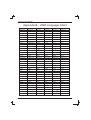
PRODUCTION RELEASE & REVISION
REV DESCRIPT'N/BUYER
DWG No
INITIAL
DATE
CHK
PARTS No. BY
------------------- 50301506
------------------- 50301611
Y.Y.KIM
Y.Y.KIM
N.C.PARK 09-25-M2
N.C.PARK 12-10-M2
210(+/-5)mm
A
A
NOTES
148(+/-5)mm
1.MODEL: AMC15LCD, AMC15LCDX / ADEMCO
2.MATERIAL: ART PAPER
WHITE
BIND : STAPLES-2
FINISH: ------------4.COLOR: TEXT-BLACK
5.SIZE: 148(+/-5)mm x 210(+/-5)mm R: 0.0
6.ANY CHANGE OR ALTERNATION MUST BE
APPROVED BY HITRON ENGINEERING.
50301611
UNLESS OTHERWISE SPECIFIED
ALL DIMENSIONS ARE IN MM.
- TOLERANCE
LABEL
+/- 1.5
MANUAL +/- 3.5
ANGULAR +/- 0.5
MATERIAL
FINISH
12 / 10
09 / 18
2
3
ITEM
DESCRIPTION/MATERIAL
QTY
PARTS LIST
APPROVALS
DATE
TITLE
N.C.PARK 12-10-M2
MANUAL INSTRUCTION
CHKED
SIZE
A4
DRAWN
Y.Y.KIM 12-10-M2
P/ N
-------
DWG No
SCALE
REV.
A
DO NOT SCALE
15-Inch Color
TFT-LCD Monitor
Installation and Operating Instructions
AMC15LCD
AMC15LCDX
All information was correct at the time of publication. ADEMCO Video
reserves the right to make changes and improvements to the product without notice.
WARNING:
TO REDUCE THE RISK OF FIRE OR ELECTRIC SHOCK, DO NOT EXPOSE THIS
PRODUCT TO RAIN OR MOISTURE. DO NOT INSERT ANY METALLIC OBJECT
THROUGH VENTILATION GRILLS.
WARNING
RISK OF ELECTRIC SHOCK
DO NOT OPEN
WARNING: TO REDUCE THE RISK
OF ELECTRIC SHOCK,
DO NOT REMOVE COVER (OR BACK).
NO USER-SERVICEABLE PARTS INSIDE.
REFER SERVICING TO
QUALIFIED SERVICE PERSONNEL.
Explanation of Graphical Symbols
The lightning flash with arrowhead symbol, within an equilateral triangle, is
intended to alert the user to the presence of uninsulated "dangerous
voltage" within the product's enclosure that may be of sufficient magnitude
to constitute a risk of electric shock to persons.
The exclamation point within an equilateral triangle is intended to alert the
user to the presence of important operating and maintenance (servicing)
instructions in the literature accompanying the product.
Safety Precautions
Should any liquid or solid object fall into the cabinet, unplug the unit and have it checked by the
qualified personnel before operating it any further.
Unplug the unit from the wall outlet if it is not going to be used for several days or more. To
disconnect the cord, pull it out by the plug. Never pull the cord itself.
Allow adequate air circulation to prevent internal heat build-up. Do not place the unit on surfaces
(rugs, blankets, etc.) or near materials(curtains, draperies) that may block the ventilation holes.
i
15-Inch Color Monitor
IMPORTANT SAFEGUARDS
1. READ INSTRUCTIONS - Read the safety and operating instructions before operating the
monitor.
2. RETAIN INSTRUCTIONS - Retain the safety and operating instructions for future reference.
3. CLEANING - Unplug video monitor from the wall outlet before cleaning. Do not use liquid
cleaners or aerosol cleaners. Use a damp cloth for cleaning.
4. ATTACHMENTS - Do not use attachments not approved by the video monitor manufacturer as
they may result in the risk of fire, electric shock or injury.
5. WATER AND MOISTURE - Do not use video monitor near water; for example, near a
bathtub, washbowl, kitchen sink, laundry tub, in a wet basement, or near a swimming pool.
6. ACCESSORIES - Do not place video monitor or equipment on an unstable cart, stand or
table. The video monitor or equipment may fall, causing serious injury and serious damage to the
equipment. Wall or shelf mounting should follow the manufacturer's instructions, and should use a
mounting kit approved by the manufacturer.
7. CARTS - Video monitor and cart combinations should be moved with
care. Quick stops, excessive force and uneven surfaces may cause the
equipment and cart combination to overturn.
8. VENTILATION - Slots and openings in the cabinet and the back or bottom are provided for
ventilation, to ensure reliable operation of the video monitor and to protect it from overheating. These
openings must not be blocked or covered. The openings should never be blocked by placing the video
monitor on a bed, sofa, rug or other similar surface. Video monitor should never be placed near or over a
radiator or heat register. Video monitor should not be placed in a built-in installation such as a bookcase
unless proper ventilation is provided.
9. POWER SOURCES - Video monitor should be operated only from the type of power source
indicated on the marking label. If you are not certain of the type of power supply you have, consult your
video monitor dealer or local power company.
10. GROUNDING OR POLARIZATION - This video monitor may be equipped with a
polarized alternating-current line plug (a plug with one blade wider than the other). This plug will fit into
the power outlet only one way. This is a safety feature. If you are unable to insert the plug fully into the
outlet, try reversing the plug. If the plug still fails to fit, contact your electrician to replace your obsolete
outlet. Do not defeat the safety purpose of the polarized plug. If your video monitor is equipped with a
three-wire grounding-type plug (a plug having a third grounding pin), this plug will only fit into a
grounding-type power outlet. This is a safety feature. If you are unable to insert the plug into the outlet,
contact your electrician to replace your obsolete outlet. Do not defeat the safety purpose of the
grounding-type plug.
ii
AMC15LCD
15-Inch Color Monitor
11. POWER CORDS - Do not allow anything to rest on the power cord. Do not locate video
monitor or equipment where the cord can be damaged by persons walking on it.
12. HEED WARNINGS - Follow all instructions marked on the video monitor.
13. LIGHTNING - During lightning storms or when the monitor will be left unattended and unused
for long periods, unplug the monitor and associated equipment from the wall outlet. This will prevent
damage to the video equipment caused by lightning and power-line surges.
14. OVERLOADING - Do not overload wall outlets and extension cords as this can result in a risk
of fire or electric shock.
15. OBJECT AND LIQUID ENTRY - Never push objects of any kind into video monitor
through openings as they may touch dangerous voltage points or short out parts that could result in a fire
or electric shock. Never spill liquid of any kind on the product.
16. SERVICING - Do not attempt to service video monitor as opening or removing covers may
expose you to dangerous voltage or other hazards. Refer all servicing to qualified service personnel.
17. DAMAGE REQUIRING SERVICE - Unplug video monitor and equipment from the wall
outlet and refer servicing to qualified service personnel under the following conditions:
A. When the power-supply cord or the plug has been damaged.
B. If liquid has spilled, or objects have fallen into the monitor.
C. If the monitor has been exposed to rain or water.
D. If the monitor does not operate normally when following the operating instructions, adjust only
those controls that are covered by the operating instructions as an improper adjustment of other
controls may result in damage and will often require extensive work by a qualified technician to
restore the monitor to its normal operation.
E. If the monitor has been dropped or the cabinet damaged.
F. When the monitor exhibits a distinct change in performance, this indicates a need for service.
18. REPLACEMENT PARTS - When replacement parts are required, be sure the service
technician uses replacement parts specified by the manufacturer or that have the same characteristics as
the original part. Unauthorized substitutions may result in fire, electric shock or other hazards.
19. SAFETY CHECK - Upon completion of any service or repairs to the monitor, ask the service
technician to perform safety checks to determine that the video product is in proper operating condition.
20. FIELD INSTALLATION - Installation should be performed by a qualified service person and
should conform to all local codes.
AMC15LCD
iii
15-Inch Color Monitor
FCC COMPLIANCE STATEMENT
INFORMATION TO THE USER: THIS EQUIPMENT HAS BEEN
TESTED AND FOUND TO COMPLY WITH THE LIMITS FOR A CLASS B
DIGITAL DEVICE, PURSUANT TO PART 15 OF THE FCC RULES. THESE
LIMITS ARE DESIGNED TO PROVIDE REASONABLE PROTECTION
AGAINST HARMFUL INTERFERENCE IN A RESIDENTIAL INSTALLATION.
THIS EQUIPMENT GENERATES, USES AND CAN RADIATE RADIO
FREQUENCY ENERGY AND, IF NOT INSTALLED AND USED IN
ACCORDANCE WITH THE INSTRUCTIONS, MAY CAUSE HARMFUL
INTERFERENCE TO RADIO COMMUNICATIONS. HOWEVER, THERE IS
NO GUARANTEE THAT INTERFERENCE WILL NOT OCCUR IN A
PARTICULAR INSTALLATION. IF THIS EQUIPMENT DOES CAUSE
HARMFUL INTERFERENCE TO RADIO OR TELEVISION RECEPTION,
WHICH CAN BE DETERMINED BY TURNING THE EQUIPMENT OFF AND
ON, THE USER IS ENCOURAGED TO TRY TO CORRECT THE
INTERFERENCE BY ONE ON MORE OF THE FOLLOWING MEASURES :
- REORIENT OR RELOCATE THE RECEIVING ANTENNA
- INCREASE THE SEPARATION BETWEEN THE EQUIPMENT AND
RECEIVER.
- CONNECT THE EQUIPMENT INTO AN OUTLET ON A CIRCUIT
DIFFERENT FROM THAT TO WHICH THE RECEIVER IS CONNECTED.
- CONSULT THE DEALER OR AN EXPERIENCED RADIO/TV TECHNICIAN
FOR HELP
CAUTION: CHANGES OR MODIFICATIONS NOT EXPRESSLY
APPROVED BY THE PARTY RESPONSIBLE FOR COMPLIANCE COULD
VOID THE USER'S AUTHORITY TO OPERATE THE EQUIPMENT.
THIS CLASS B DIGITAL APPARATUS COMPLIES WITH CANADIAN ICES003.
NORME NMB-003 DU CANADA.
THIS PRODUCT COMPLIES WITH VARIOUS OTHER REGIONAL AND
SAFETY REGULATIONS SUCH AS: UL, CUL, CE. THESE
CERTIFICATIONS ARE NOTED ON THE PRODUCT LABEL.
iv
AMC15LCD
15-Inch Color Monitor
Table of Contents
Chapter 1 - Introduction
1
Features
1
Chapter 2 - Installation
2
Connections
9
Chapter 3 - Operation
10
User Controls
12
Appendix A - Specifications
Appendix B - OSD Language Chart
Appendix C - Bracket Features
Appendix D - Stand Features
Appendix E - Troubleshooting
15
17
18
19
20
List of Illustrations
Figure 1 - Typical configuration
Figure 2 - Front panel controls
Figure 3 - Rear panel connectors
1
10
11
AMC15LCD
v
15-Inch Color Monitor
Chapter 1 - Introduction
AMC15
LCD Monitor
PC
Typical Time-Lapse Recorder Rear Panel
Camera or other video source
VIDEO
AUDIO
OUT
IN
Optional Loop-out to another video device
Figure 1 -Typical configuration
Features
Go-Anywhere Professional Color LCD Monitor
Bright, High Quality Picture
NTSC and PAL Composite and Y/C Connectors.
Thin and Lightweight, Rugged Metal Cabinets
Many Mounting and Installation Options
Low Power Consumption. - 12 Volts DC Operation.
AMC15LCD
1
15-Inch Color Monitor
Chapter 2 - Installation
LCD monitors may be mounted in any position or orientation. Considerations for
mounting include regard for how the monitor is going to be used, routing of
connecting cords, and locations away from heat sources (including direct sunshine
on the black case).
Mounting attatchment points include 10-32 inserts.
Cooling is not required, but some airflow around the case will
allow the small amount of heat to be dissipated.
Power is required from a regulated supply (provided) or other 12 volts DC source.
The noise on the supply must be below 100 mVpp.
CAUTION: Many portable battery systems, including automobiles,
with a nominal 12 VDC supply often have power spikes and can
operate as high as 18 VDC while charging. Make certain your power
supply meets the 12 VDC 10% requirements.
Plug and Play
The VESA plug and play standard eliminates a complicated, time consuming setup.
It allows you to connect your monitor to a Plug and Play compatible system without
the usual hassles and confusion. Your PC system can easily identify and configure
itself for use with your display.
Installing the Video Driver (Windows 95/98)
To install the Video driver, refer to the following sequence.
Select Start/Setting/Control Panel.
2
AMC15LCD
15-Inch Color Monitor
Click Add New Hardware.
Click Next.
AMC15LCD
3
15-Inch Color Monitor
Click Next.
Click Next after selecting No, the device isn't in the list.
4
AMC15LCD
15-Inch Color Monitor
Click Next after selecting No, I want to select the hardware from a list.
Click Next after selecting Monitors.
AMC15LCD
5
15-Inch Color Monitor
Click Have Disk....
Insert the supplied 3.5 floppy disk in A Drive.
Select OK.
6
AMC15LCD
15-Inch Color Monitor
Select Next after selecting the same model which you purchased.
Click Finish.
AMC15LCD
7
15-Inch Color Monitor
Microsoft Windows 2000 Operating System
1. Click "Start", "Setting", "Control Panel".
2. Double click the "Display" Icon.
3. Choose the "Settings" tab and then click "Advanced..".
4. Choose "Monitor".
Case1: If the "Properties" button is inactive, it means your monitor is properly configured.
Please stop the installation; there is no need to continue.
Case2: If the "Properties" button is active, click the "Properties" button then follow next
steps continuously.
5. Click "Driver" and then click on "Update Driver..." then click on the "Next" button.
6. Choose "Display a list of the known drivers for this device so that I can choose a
specific driver" then click "Next" and then click "Have disk".
7. Click the "Browse" button then choose A:.
8. Click the "Open" button, then click "OK" button.
9. Choose 15" LCD and click the "Next" button then click the "Next" button again.
10. Click the "Finish" button then the "Close" button.
If you can see the "Digital Signature Not Found" window then click the "Yes" button.
And click the "Finish" button then the "Close" button.
Microsoft Windows Millennium Operating System
1. Click "Start" , "Setting" , "Control Panel".
2. Double click "Display" icon.
3. Select the "Settings" tab and click the "Advanced Properties" button.
4. Select the "Monitor" tab.
5. Click the "Change" button in the "Monitor Type" area.
6. Choose "Specify the location of the driver".
7. Choose "Display a list of all the drivers in a specific location.." then click "Next" button.
8. Click the "Have Disk" button
9. Specify A: then click the "OK" button.
10. Select "Show all devices" and choose 15" LCD and click "OK".
11. Continue by choosing the "Close" button and "OK" button until you close the Display
Properties dialogue box.
(If other warning screens appear, select the appropriate options for your monitor.)
Microsoft Windows XP Operating System
1. Click "Start" > "Control Panel" then click the "Appearance and Themes" Icon.
2. Click the "Display" icon and choose the "Settings" tab then click "Advanced..".
3. Click the "Properties" button on the "Monitor" tab and select the "Driver" tab.
4. Click "Update Driver..." and select "Install from a list or.." then click the "Next" button.
5. Select "Don't search, I will..." then click "Next" and then click "Have disk".
6. Click the "Browse" button then choose A: and choose 15" LCD and click the "Next" button.
7. If you see a "Message" window stating that the driver has not passed Window testing, click
the "Continue Anyway" button. The click "OK" button.
Although the monitor driver is not certified by Microsoft, it will not damage your system.
8. Click the "Close" button then click the "OK" button repeatedly.
9. The Monitor driver installation is completed.
Microsoft Windows NT Operating System
1. Click "Start", "Settings", "Control Panel", and then double-click "Display" icon.
2. In the Display Registration Information window, click the Settings Tab and then click "All
Display Modes".
3. Select a mode that you wish to use (Resolution, Number of colors and Vertical frequency)
and then click "OK".
4. Click the "Apply" button if you see the screen operating normally after clicking Test. If the
Screen is not normal, change to a different mode (lower mode of resolution, colors or
frequency).
Note: If there is no Mode at "All Display Modes", select the level of resolution and vertical
frequency by referring to the Preset Display Modes in the user guide.
8
AMC15LCD
15-Inch Color Monitor
CONNECTIONS
To make a normal connection to the monitor, route a cable from a camera or other
video source to one of the BNC jacks or from a PC to the PC jack on the back of
the monitor. Either the left or right BNC jack can be used for input.
The other jack may be connected to another device using the same input signal..
Auto Termination
The input circuit of the monitor normally terminates the incoming cable with 75 ,
but these BNC connectors are auto-terminating. When two cables are connected,
the internal termination is switched off, letting the last unit in the system provide
the end termination. The Y/C (S-Video) jacks function this way as well.
Typical LCD monitor back
PC
Typical Time-Lapse Recorder Rear Panel
Camera or other video source
VIDEO
AUDIO
OUT
IN
Optional Loop-out to another video device
AMC15LCD
9
15-Inch Color Monitor
Chapter 3 - Operation
7
1
2
3
4
5
6
Control Buttons, Video Monitor Front.
Use a cloth dampened with a mild cleaner to clean the screen.
Figure 2 - Front panel controls
1. Power On/Off
When power is applied, the monitor will come on. This button then turns the
monitor on and off.
2. Menu On/Off
This button is used to display or turn off the control menu.
3. Select Down
This button is used to move down the menu list.
4. Select Up
This button is used to move up through the menu list.
5. Decrement
Pressing this button decreases the value of the chosen item.
For some items, the button will change the setting to ' On '
6. Increment
Pressing this button increases the value of the chosen item.
For some items, the button will change the setting to ' Off '
7. LED
A green indicator lights when the power is on. (The indicator will not light
when the power is off.) The indicator blinks when the monitor goes into the
standby mode (PC mode).
10
AMC15LCD
15-Inch Color Monitor
5
4
2
1
3
6
Typical Color LCD Video Monitor Back
Figure 3 - Rear panel connectors
1. Input Connector Recess
Recessed wiring location for all cables. Connect the plug from the supplied
table-top power supply into the 12 VDC connector. Input at the monitor is 12
volts DC from the TT universal AC supply (100-240 VAC, see specifications
table for AC/DC details).
2. Input Video BNC (and Y/C) and PC Connectors
Attach the video cable from a camera, VCR, or other source here. Either left or
right, BNC or Y/C socket, can be input or output. The connector have autotermination switches inside. See Connections, below.
3. Speakers
Audio inputs are high impedance using RCA jack connections, left (white) and
right (red). Inserting only a single plug will make a connection to both speakers
(dual monaural).
4. Mounting Keyholes
You may hang monitors on a wall using screw or nail heads. The heads
should not enter the monitor deeper than 1/4 " (6 mm).
5. Threaded Mounting Socket
The threaded sockets are hardpoints for mounting the monitor. You may
mount it in any orientation. The screws must not insert deeper than 1/4 "
(6 mm). The threads are 10-32 UNC.
AMC15LCD
11
15-Inch Color Monitor
USER CONTROLS - Menu Operations
PC
Brightness
Contrast
Clock
Phase
Auto
H Position
V Position
RGB Offset
Image Effect
Volume
Language
Input
Recall
: 25
: 41
: 125
: 16
: Stop
:0
:0
:0
:5
: 10
: English
: PC
: No
Pressing the MENU button will bring up the Menu shown above.
Select the item you want to adjust using the , buttons
As shown, the Brightness may be adjusted with the or buttons.
To exit the menu, press the MENU button.
(This process stores the new settings which you have selected.)
Brightness is used to adjust the light output of the darkest areas of the picture
to black.
Contrast is used to adjust the light output of the brightest areas of the picture to
White.
Clock is used to adjust best picture quality. The clock adjusts the number of
pixels in the horizontal line. Therefore it can affect the picture poisition and size
horizontally.
Phase is used to adjust best picture quality. It adjusts the sampling phase across
one pixel time. When the phase is not adjusted properly, the picture quality is not
good. Therefore this value should be carefully adjusted.
Auto
Select "Yes" using or buttons to adjust the best picture quality automatically.
Execute repeatedly if the picture quality is not good.
H Position is used to adjust the horizontal position of the image on the screen.
V Position is used to adjust the vertical position of the image on the screen.
RGB Offset
RGB Offset is used to adjust the video input range. When the bright areas of the
picture is too high (low), increase (decrease) the RGB Offset value.
Image Effect is used to soften or sharpen the image.
Volume controls the output of the internal speakers.
12
AMC15LCD
15-Inch Color Monitor
Language : English sets the OSD language of the menu to English.
Deutsch sets the OSD language of the menu to German.
Fran ais sets the OSD language of the menu to French.
Italiano sets the OSD language of the menu to Italian.
Espa ol sets the OSD language of the menu to Spanish.
Polski sets the OSD language of the menu to Polish.
Input selects between the PC, composite (BNC) or Y/C (4 pin S-video) for the
video source.
Recall sets the monitor to the original factory setting.
VIDEO
Volume
Contrast
Brightness
Sharpness
Color
Tint
Language
Scaler Motion
Under Scan
Input
Filter
AFC
DVCO
Recall
: 10
: 41
: 23
:5
: 30
: 25
: English
: Motion
: OFF
: CVBS
: OFF
: Fast
: 25
: No
Pressing the MENU button will bring up the Menu shown above.
Select the item you want to adjust using the , buttons
As shown, the Brightness may be adjusted with the or buttons.
To exit the menu, press the MENU button.
(This process stores the new settings which you have selected.)
Volume controls the output of the internal speakers.
Contrast is used to adjust the light output of the brightest areas of the picture
to white.
Brightness is used to adjust the light output of the darkest areas of the picture
to black.
Tip: Use the Brightness to make the details in the dark areas of the
picture to be just visible, and Contrast to "brighten" the picture without
causing facial features to turn white.
AMC15LCD
13
15-Inch Color Monitor
Sharpness adjusts the sharpness of the picture.
Tint adjusts all the colors on the screen, but is most noticeable to the eye in reds
and yellows, and is also usually set for pleasing facial tones.
(Appears in NTSC mode only).
Language: English sets the OSD language of the menu to English.
Deutsch sets the OSD language of the menu to German.
Fran ais sets the OSD language of the menu to French.
Italiano sets the OSD language of the menu to Italian.
Espa ol sets the OSD language of the menu to Spanish.
Polski sets the OSD language of the menu to Polish.
Motion Mode changes the scanning method of the LCD monitor.
Tip: There are three methods which can be controlled.
(Still/Progressive/Motion)
Still and Progressive modes are progressive scan but Progressive is
better than Still for moving images and Still is better than Progressive
for still images. Motion uses interlace scan.
However, use Toggle mode when the video source contains
moving images. (For example, DVD or VCR)
Under Scan adjusts the image size.
Input selects between the composite (BNC) or Y/C (4 pin S-video) inputs for the
display.
Filter adjusts Filter "ON" to reduce the output video noise.
AFC (auto frequency control) is used to adjust for the skew distortion of a video
signal from a recorder (or other equipment).
The options are : NORMAL, SLOW, and FAST.
DVCO is used to reduce unwanted moving vertical lines.
Tip : In some case, vertical lines flowing to the right or left appear
depending on the video source.
When flowing vertical lines appear, it is convenient to reduce them by
adjusting the DVCO.
Recall sets the monitor to the original factory settings.
Hot Keys Without pushing the menu button, the left( , ) and right pairs
( , ) of buttons function as direct access buttons (Hot keys).
The left pair adjusts Brightness, and the right pair adjusts Volume.
14
AMC15LCD
15-Inch Color Monitor
Appendix A - Specifications
(15 inch)
LCD
LCD panel
Active display area (Diagonal)
Pixel format
Pixel pitch
Color depth
Contrast ratio
Brightness
Viewing angles (L/R/U/D)
Light source / Lifetime
Response time(tr/td)
VIDEO
Video Mode
Scanning method
Video input signals
Composite
S-video
Video connector
Composite
S-video
Termination
Audio input connector
Audio Amplifier
Resolution
PC
Input signal
Input connector
Input resolution
Plug & Play
User controls
AMC15LCD
15
15.0 inches TFT LCD Panel
15.0 inches
1024(H) x 768(V), RGB vertical stripe
0.297mm x 0.297mm
6 Bit/262,144 Colors
300:1 (Typical)
2
250 cd/m (Typical)
70/70/55/60 (Typical)
4 CCFL/35,000 Hrs (Typical)
5/20 ms
NTSC/PAL (Auto selection)
Digital progressive scan (Frame/Motion
mode)
1.0Vp-p, 75
0.7Vp-p(Luminance), 75
0.3Vp-p(Chrominance), 75
BNC x 2
4 Pin Mini-DIN x2
75 , Auto termination
RCA x 2 (Stereo)
0.5W x 2
More than 500 Lines
Analog RGB (0.714Vp-p, 75 ),
H&V Sync (TTL)
15-pin D-sub
VGA 640 x 480, 60~75Hz
SVGA 800 x 600, 56~75Hz
XGA 1024 x 768, 60~75Hz
DDC 2B
Brightness, Contrast, Tint, Color,
Sharpness, etc.
15-Inch Color Monitor
OSD Language
Power requirement
Power consumption
DC power connector
AC power connector
Dimensions
Weight
Operating temperature
Storage temperature
Case color
Case material
Accessories
English/French/German/Italian
/Spanish/Polish
12VDC 3.0A
30 Watts
Barrel, 5.5/2.5mm (+Center)
IEC-320 Male, 100-240VAC
349.2mm(W) x 285.7mm(H) x44.5mm(D)
6 lbs.(2.7Kg)
o
o
0 C ~ +40 C
o
o
0 C ~ +50 C
Black
Aluminum
AC Adaptor, VGA cable, Power Cord,
Manual, Driver Diskette
* Design and specifications are subject to change without notice.
16
AMC15LCD
15-Inch Color Monitor
Appendix B - OSD Language Chart
English
German
French
Italian
Spanish
Polish
No Signal
No Signal
No Signal
No Signal
No Signal
No Signal
NTSC
NTSC
NTSC
NTSC
NTSC
NTSC
PAL
PAL
PAL
PAL
PAL
PAL
Volume
Lautstarke
Volume
Volume
Volumen
Glosnosc
Contrast
Kontrast
Contraste
Contrasto
Contraste
Kontrast
Brightness
Helligkeit
Luminosite
Luminosita
Brillante
Jansnosc
Sharpness
Scharfe
Nettete
Definizione
Nitidez
Ostrosc
Color
Frabkontrast
Couleur
Colore
Color
Kolor
Tint
Tonung
Nuance
Tinta
Tinte
Odcien
Language
Sprache
Langues
Lingue
Idioma
Jezyk
English
Deutsch
Fran ais
Italiano
Espa ol
Polski
Motion Mode
Motion Mode
Motion Mode
Motion Mode
Motion Mode
Motion Mode
Still
Still
Still
Still
Still
Still
Progressive
Progressive
Progressive
Progressive
Progressive
Progressive
Motion
Motion
Motion
Motion
Motion
Motion
Under Scan
Under Scan
Under Scan
Under Scan
Under Scan
Under Scan
Filter
Filter
Filtre
Filtro
Filtro
Filtr
DVCO
DVCO
DVCO
DVCO
DVCO
DVCO
On
Ein
Marche
On
On
Wl
Off
Aus
Arret
Off
Off
Wyl
Input
Quelle
Input
Sorgente
Fuente
'
Wejscie
CVBS
CVBS
CVBS
CVBS
CVBS
CVBS
Y/C
Y/C
Y/C
Y/C
Y/C
Y/C
PC
PC
PC
PC
PC
PC
Recall
Zuruckrufen
Rappel
Richiamare
Recuperar
Przywoyanie
Yes
Ja
Oui
Si
Si
Tak
No
Nein
Non
No
No
Nie
Clock
Uhr
Horlage
Orodogio
Jeloz
Clock
Phase
Phase
Phase
Face
Phase
Phase
Auto
Auto
Auto
Auto
Auto
Auto
Run
Run
Run
Run
Run
Run
Stop
Stop
Stop
Stop
Stop
Stop
H Position
H Stellung
H Position
H Posizione
H Posici n
H Position
V Position
V Stellung
V Position
V Posizione
V Posici n
V Position
RGB Offset
RGB Offset
RGB Offset
RGB Offset
RGB Offset
RGB Offset
AMC15LCD
17
15-Inch Color Monitor
Appendix C - Bracket Features (Optional)
- Light duty wall & ceiling mount
- Adjustable swivel head
- Die cast and aluminum
- Cable feeds through hole concealing wiring
1
- PT 1 / 4 threaded pipe
- Maximum load 20 lb ( 9.0kg )
The Bracket is light duty wall & ceiling mount
designed for use with LCD monitor.
This mount is for use in wall & ceiling mounting
applications and is capable of supporting
loads up to 20 lb ( 9.0kg ).
o
75.0(100.0)
15
75.0(100.0)
Pan adjustment
Tilt adjustment
LCD mounting
Construction
Finish
Maximum load
Dimension
Weight
Unit: mm
Unlimited 180o
o
o
-5 ~ 15 (up or down)
four(4) M4 x 15L
machine screw (supplied).
Die cast and aluminum
Light-gray polyester powder coat
20 lb ( 9.0kg )
See dimensional outline
Unit
Shipping
4.4lb (2.0kg)
3.5lb (2.5kg)
18
AMC15LCD
15-Inch Color Monitor
Appendix D - Stand Features (15'', Optional)
4
2
1
3
1. SCREW
2. BRACKET
3. HINGE
4. HINGE_COVER
5. STAND
5
In order to install the desk-top stand at LCD monitor properly,
First, fix the metal plate provided to the hinge of desk-top stand with 4 screws of
M4 size and screw the desk-top stand to LCD monitor. Lastly, put the plate cover
on the hole located on the rear side of LCD monitor .
Note: Because the metal plate has VESA standard mounting holes at 75mm
intervals, it can be used with other VESA standard monitors.
Tilt adjustment
LCD mounting
Construction
Finish
Maximum load
Dimensions
Weight
AMC15LCD
19
o
o
-5 ~ 30 (up or down)
eight (8) M4 x 8L
Plastic and Metal
Paint
4.5kg
256.5mm x 165mm x 190mm
With 15" (Height): 355mm
With 17" (Height): 371.25mm
Unit
Shipping
1.2kg
1.5kg
15-Inch Color Monitor
Appendix E - Troubleshooting
Problem
Possible Solution
No Video
Check that all components in the system (monitor, cameras,
VCRs, multiplexers, etc.) have power and are turned on.
Check that the camera lens cap is removed and the lens is set
to proper aperture.
Check cable(s) for proper connections and condition.
Connect a known good video source directly to the monitor to
make certain the monitor is not the Problem.
Bad Video
If no video equipment is "looped through" the monitor, make
certain that a cable is NOT connected to the loop-through
connector.
Poor video quality
Adjust the Contrast, Brightness and Color settings.
Picture too bright
or too dark
Check that the lens aperture is set correctly.
Fuzzy Video
If the camera has a manual focus lens, check that it is properly
focused.
Adjust the Brightness setting.
If the camera has an autofocus lens, ensure that it is working
properly.
Check that the back focus ring on the camera has been adjusted
correctly.
Check that the lens and housing window are clean.
20
AMC15LCD
(Headquarters)
175 Eileen Way
Syosset, NY 11791
USA
1-516-921-6704
Customer Service:
800-467-5875
Applications:
877-653-0302
Technical Support:
877-718-0746
Fax:
516-921-0491
Web site:
www.ademco.com/ademcovideo
ADEMCO International (Headquarters)
180 Michael Drive
Syosset, NY 11791
USA
1-516-921-6704
AUSTRALIA
ADEMCO Australia
Unit 5, Riverside Centre
24-28 River Road West
Parramatta, NSW 2150
Australia
61-2-8837-9300
ASIA/PACIFIC
ADEMCO Asia Pacific
Flat A&B, 7/F, CDW Building
388 Castle Peak Road
Tsuen Wan, N.T
Hong Kong
852-2405-2323
LATIN AMERICA
ADEMCO International (Latin America)
ADEMCO Brasil
Rua Eng, Isaac Milder, 500
Sao Paulo, SP
Brasil
CEP: 05688-010
55-11-3758-6111
EUROPE
ADEMCO France
Parc Gutenberg
13, Voie La Cardon
91120, Palaiseau
France
33-1-69321090
ADEMCO Italia SpA
Via della Resistenza, 53/59
20090 Buccinasco MI
Italy
39-02-457-179-1
ADEMCO Sontrix Espa a
Vivero 528040
Madrid
Spain
34-91-533-4706
Security House
Amperestraat 41
1446 TR Purmerend
Netherlands
31-299-419-000
Video Controls Ltd.
Aston Fields Rd.
Whitehouse Ind. Est
Runcorn
UK WA7 3DL
44-928-754000
9315 NW 112 Avenue
Miami, FL 33178
1-305-805-8188
AMC15LCD &
AMC15LCDX
50301611A