1
Shark
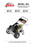
MODEL B2535H/1
OPERATING INSTRUCTIONS
AND PARTS MANUAL
R
Read instructions carefully before attempting to assemble, install, operate or service this pressure
washer. Failure to comply with instructions could result in personal injury and/or property damage!
SPECIFICATIONS
● Pump Volume At Pump Head: 3.5 GPM/210 GPH
● Pump Pressure At Pump Head: 2500 PSI
● Machine Power: 9.0 HP Gasoline Engine, Manual Start
● Machine Weight: 145 Lbs.
● Shipping Weight: 185 Lbs.
● Machine Dimensions: Length = 34”, Width = 24.5”, Height = 23.5”
Output specifications are based on engine power curves at 100 meters
above sea level and 25o C ambient temperature in accordance with
SAE J1349.
SERIAL NUMBER:
SHARK PRESSURE WASHERS
21 INVERNESS WAY EAST
ENGLEWOOD, CO 80112
1-800-771-1881
DATE PURCHASED:
FOR SALES AND SERVICE, PLEASE CONTACT:
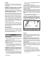
WARNING
Read and observe to prevent severe personal injury or property damage.
●
Check hoses, fittings, wand, and trigger
gun daily for signs of wear, cracks and
looseness, and replace as required.
●
Use extreme caution when moving
pressure washer over rough or uneven
surfaces.
●
Do not point wand or trigger gun at yourself or at any person. Bodily injury may
result from water under high pressure.
●
●
Do not block or tie trigger gun in open
position.
For permanent installation consult local
building codes for installation requirements. Licensed contractor may be
required.
●
Disconnect spark plugs prior to performing any maintenance.
●
Pressure washers produce a kickback. To
prevent personal injuries due to falls use
auxiliary safety equipment.
●
When applying detergents follow the
safety rules on the detergent label.
●
Use detergent from a covered D.O.T.
approved container.
●
Cleaning area should be provided with
adequate slopes and drainage. This will
reduce the possibility of a fall due to slippery surface.
●
Unauthorized machine modification or use
of non-approved replacement parts may
cause personal injury and/or property
damage and will void the manufacturer
warranty.
●
This machine has been provided with
Warning and Instruction decals for the
safety of the operator. If these decals are
removed or become damaged they should
be replaced. Contact your dealer for
replacement decals.
●
Wear eye, ear, hand, foot, and skin protection at all times while operating pressure washer.
●
Do not allow machine to run unattended.
●
Avoid contact with non-insulated areas of
pressure washer to prevent the possibility of severe burns.
●
●
Do not run machine indoors or in an
enclosed area, as exhaust fumes may be
hazardous to your health.
Do not operate machine in areas where
flammable vapors (gasoline, solvents,
etc.) may be present, as this machine may
ignite the vapors.
●
Do not store flammable liquids (gasoline,
diesel fuel, solvents, etc.) near pressure
washer or in non-ventilated areas.
●
Do not fill engine fuel tank while engine
is running or hot. Let engine cool before
refueling or spontaneous fire may result.
Fuel spillage or vapors could ignite if
engine is hot.
●
Do not place hands or feet on noninsulated areas of the pressure washer
when starting gasoline engine.
Page 2
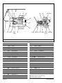
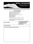
Shark B2535H/1
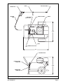
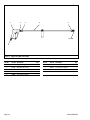
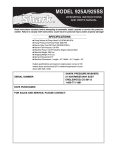
TRIGGER GUN
WAND
PRESSURE
HOSE
PRESSURE NOZZLE
NOZZLE HOLDERS
PRESSURE
RELIEF VALVE
ENGINE
24.5”
PUMP
THERMAL RELIEF VALVE
34”
UNLOADER VALVE
PRESSURE HOSE
CONNECTOR
23.5”
GARDEN HOSE
CONNECTOR
Figure 1 - Machine Component Layout
Shark B2535H/1
Page 3
ASSEMBLY
2. Assemble wand components as shown in Figure 3.
NOTE: The pressure nozzle is not to be installed at
this time.
Unpacking
Unpack carefully. Wear safety glasses or goggles while
unpacking, assembling, or operating pressure washer. If
there are missing components or hidden damage, immediately contact carrier concerning discrepancies.
TRIGGER GUN
Parts Included
•
•
•
•
•
•
•
Pressure Washer
Pressure Hose
Pressure Nozzle (4 Ea.)
Wand
Trigger Gun
Operating Instructions and Parts Manual
Gasoline Engine Manual
WAND
PRESSURE HOSE
Figure 3 - Trigger Gun/Dual Lance Wand
Pressure Hose, Trigger Gun and Wand
3. Make sure all connections are secure.
1. Install the pressure hose on the pressure washer as
shown in Figure 2.
INSTALLATION
Getting Started
PRESSURE HOSE
PRESSURE HOSE
CONNECTOR
IMPORTANT: Proper initial installation of equipment
will assure more satisfactory performance, longer service life, and lower maintenance cost.
IMPORTANT: The use of a backflow preventer on the
water supply hose is recommended and may be
required by local code.
Figure 2 - Pressure Hose Installation
Page 4
The pressure washer should be run on a level surface
and in a protected area where it is not readily influenced
by outside forces such as strong winds, freezing temperatures, rain, etc. The pressure washer should be
located to assure easy access for filling of fluids, adjustments and maintenance. Normal precautions should be
taken by the operator to prevent moisture from reaching
the pressure washer. It is recommended that a partition
be made between the wash area and the pressure washer
to prevent direct spray from the wand from coming in contact with the pressure washer. Moisture reaching the
equipment will reduce the pressure washer’s service life.
All installations should comply with the local codes
covering such installations.
Shark B2535H/1
Venting
DANGER: Do not run machine indoors or in an
enclosed area, as exhaust fumes may be hazardous
to your health.
DANGER: Do not operate machine in areas where
flammable vapors (gasoline, solvents, etc.) may be
present, as this machine may ignite the vapors.
CAUTION: All venting must be in accordance with
applicable federal and state laws, and local ordinances. Consult local contractors.
If the pressure washer is to be used in an enclosed area,
a flue must be installed to vent engine exhaust to the
outside atmosphere. When selecting the location for
operation, beware of poorly ventilated locations or areas
where exhaust fans may cause an insufficient supply of
oxygen. Proper combustion can only be obtained when
there is a sufficient supply of oxygen available for the
amount of fuel being burned. If it is necessary to use the
machine in a poorly ventilated area, outside fresh air may
have to be piped to the engine and a fan installed to bring
sufficient air into the machine.
In addition, the pressure washer should never be operated in an enclosed area where high ambient temperatures exist. High ambient temperatures (above 100o F)
can cause engine oil failure and will greatly reduce the
engine’s performance.
Refer to the provided gasoline engine manual for
additional details.
4. Check pump and engine oil levels.
IMPORTANT: Before installing nozzle on initial startup, turn on the water supply and allow water to run
from the end of the wand until clear to prevent the
nozzle from clogging.
IMPORTANT: If the pressure washer has not been
used for an extended period of time, remove the nozzle
from the end of the wand and turn on water supply.
Allow water to run from the end of the wand until
clear.
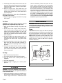
5. Install the proper pressure nozzle for your cleaning
needs on end of wand, refer to Figure 4.
IMPORTANT: The trigger gun provided with this pressure washer is equipped with a manual trigger lock
to prevent accidental operation of the trigger gun,
refer to Figure 4. The trigger lock should be used
whenever the trigger gun is not in use.
MANUAL TRIGGER
LOCK
PRESSURE
NOZZLE
Gasoline Engine
This gasoline engine is preset for operation at altitudes
below 3000 feet above sea level. If operated at higher
altitudes, it may be necessary to install a high altitude
main jet in the carburetor. Contact an authorized engine
sales and service center for details.
Figure 4 - Nozzle Installation/Manual Trigger Lock
To Start
OPERATION
Before Starting
1. Read all manuals provided with this pressure washer.
Become familiar with location and function of all
operating and safety controls.
WARNING: Check hoses, fittings, wand, and trigger
gun daily for signs of wear, cracks and looseness,
and replace as required.
2. Connect water supply hose to the garden hose connector located on the pump. The water faucet and supply hose must be capable of providing a minimum of
3.5 gallons per minute (GPM).
WARNING: Do not fill engine fuel tank while engine
is running or hot. Let engine cool before refueling or
spontaneous fire may result. Fuel spillage or vapors
could ignite if engine is hot.
3. Fill the engine fuel tank. Do not overfill, fill to the bottom of filler neck only. Use lead free gasoline minimum 86 octane. DO NOT use gasoline containing
more than 5% methanol, 10% ethanol, or 15% MTBE.
Shark B2535H/1
DANGER: Do not point wand or trigger gun at yourself or at any person. Bodily injury may result from
water under high pressure.
WARNING: Wear eye, ear, hand, foot and skin protection at all times while operating pressure washer.
IMPORTANT: The water must be turned on before
starting. Running the pump dry will cause damage
and void warranty.
IMPORTANT: Do not allow the machine to run with
trigger of the trigger gun released for more than
10 minutes at any one time or damage to pump may
occur.
1.
2.
3.
4.
Turn ON water supply.
Hold wand firmly, release trigger of trigger gun.
Place engine ON/OFF switch in the ON position.
Turn fuel shut-off valve to ON position (if so equipped).
Move choke lever to full choke position, (choke may
not be needed on warm engine). Move throttle lever
to half throttle position.
Page 5
5. Pull the rope starter slowly until resistance is felt, then
pull briskly. Do not allow the rope starter to snap back
against the engine. Return it gently to prevent damage to the starter.
6. When the engine star ts, move choke lever until
engine runs smoothly. Move throttle lever to full throttle
position. When engine warms, move choke lever to
no choke position.
NOTE: If engine fails to start, refer to Troubleshooting Guide in this manual.
7. Squeeze trigger of trigger gun and allow air to purge
from system.
solvent to antifreeze). To flush the system with antifreeze, attach a short length of hose to the garden
hose connector located on the pump. Place the
other end of the hose into a container of antifreeze.
Start machine and allow to run until antifreeze flows
from the end of the wand. Squeeze and release the
trigger of the trigger gun several times to antifreeze
the unloader system. If the pressure washer is not to
be used for an extended length of time, it is recommended that the system be flushed with antifreeze
for rust protection. Refer to provided gasoline engine
manual for engine storage information.
MAINTENANCE
To Clean
DANGER: Do not place hands or fingers in front of
high pressure spray. Bodily injury may result.
1. Wash from the bottom to the top, using side to side
motions.
2. Do not wash at a 90o angle to work (straight at it).
This will allow water to splash back at you and
reduces your cleaning power. Wash at a 30o to 60o
angle to the work. This will allow the water to splash
away from you and the water will wash the dirt away
faster and easier.
3. Use the full width of the spray pattern to wash in a
wide path. Overlap spray paths for complete coverage. Wash from side to side, using slow, steady
motions.
4. The nozzle should be 12" to 24" from work, closer for
tough areas. Be careful on painted or delicate surfaces, the pressure may damage surface if nozzle is
too close.
5. Small parts should be washed in a basket so the pressure does not push them away. Larger, lightweight
parts should be clamped down so the pressure does
not push them away.
WARNING: Unauthorized machine modification or use
of non-approved replacement parts may cause personal injury and/or property damage and will void the
manufacturer warranty.
Pump
Lubrication: To lubricate pump, use 30W non-detergent
oil for pump crankcase. Crankcase must be filled to the
full mark on the dipstick or to the center of sight glass
window found on the rear or side of the pump, refer to
Figure 5. During the break-in period, make sure the oil is
changed after the first 25 hours of operation. After that,
replace oil every 3 months or 300 hours of operation,
whichever comes first.
SIGHT GLASS
OIL FILL/DIPSTICK
To Stop
1. Move throttle lever to idle position.
2. Turn engine ON/OFF switch to the OFF position.
3. Turn fuel shut-off valve to OFF position (if so
equipped).
4. Turn water supply OFF.
5. Squeeze trigger of trigger gun to relieve system
pressure.
OIL DRAIN
SIGHT GLASS
Figure 5 - Pump Lubrication
STORAGE
DANGER: Do not store flammable liquids (gasoline,
diesel fuel, solvents, etc.) near pressure washer, or
in non-ventilated areas.
1. Protect from freezing by storing in a heated area, or
by flushing the system with antifreeze (use an automotive engine antifreeze or windshield washer
Page 6
Shark B2535H/1
Proper Pump Care:
• Do not pump acids.
• Do not allow pump to run dry.
• Winterize if storing in freezing temperatures, refer
to Storage for details.
• Use a water softener on the water system if known
to be high in mineral content.
• Flush the pressure washer system with antifreeze
if storing for an extended period of time, refer to
Storage for details.
Gasoline Engine
Refer to the provided gasoline engine manual for recommended maintenance.
Shark B2535H/1
Pressure Relief Valve
WARNING: The pressure relief valve on this pressure
washer has been factory set and sealed and is a field
nonadjustable part. Tampering with the factory setting may cause personal injury and/or property damage, and will void the manufacturer warranty. For
replacement refer to Figure 7.
Unloader Valve
WARNING: The unloader valve on this pressure
washer has been factory set and sealed and is a field
nonadjustable part. Tampering with the factory setting may cause personal injury and/or proper ty
damage, and will void the manufacturer warranty. For
replacement refer to Figure 7.
Page 7
TROUBLESHOOTING GUIDE
SYMPTOM
POSSIBLE CAUSES
CORRECTIVE ACTION
Gas engine will not run.
Out of gas.
Replenish supply. Use only recommended fuels. Refer to Before Starting under Operation.
Fuel valve closed (if so equipped).
Open valve.
Loose spark plug wire.
Reconnect.
Choke or throttle set incorrectly.
Refer to To Start under Operation.
Engine ON/OFF switch in OFF
position.
Place engine ON/OFF switch in ON
position.
Low engine oil level.
Replenish supply. Engine will not start
or run if oil is low (on engines equipped
with low oil protection).
Refer to provided gasoline engine manual for additional troubleshooting.
Pressure washer runs
but won't spray.
Low spray pressure at
pressure nozzle.
Uneven spray pattern.
Trigger of trigger gun released.
Squeeze trigger.
Water supply not turned on.
Open water supply valve.
Clogged pressure nozzle.
Clean pressure nozzle opening.
Inadequate water supply.
Fully open faucet. Check for kinked or
damaged hose. Use 5/8 inch minimum
hose. Check for debris clogging inlet
screen.
Partially clogged or damaged
pressure nozzle.
Clean or replace.
Engine throttle not in full throttle
position.
Place engine throttle in full throttle
position.
Partially clogged or damaged
pressure nozzle.
Clean or replace.
IMPORTANT
If the pressure washer demonstrates other symptoms or the corrective actions listed do not correct the problem, contact the local authorized Shark
Pressure Washer Service Center. The Shark Pressure Washer Service Center can be identified by contacting:
Customer Service Department
Shark Pressure Washers
21 Inverness Way East • Englewood, Colorado 80112
1-800-771-1881
Page 8
Shark B2535H/1
When ordering from your dealer, please provide the following:
Model Number: B2535H/1
Machine Serial Number: ________________________________
Component Part Number: _______________________________
Description: __________________________________________
FOR HELP OR ADDITIONAL INFORMATION, CONTACT:
Customer Service Department
Shark Pressure Washers
21 Inverness Way East
Englewood, CO 80112
1-800-771-1881
B2535H/1 OPTIONAL EQUIPMENT
280268
Detergent Injector Kit
Shark B2535H/1
Page 9
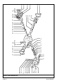
1
38
25
2
5 35
3
6
14
24
36
26,27,28
33
9
7
13
10,11
12
4,29,
34,39
8
15,16
30,3 1,32 17 19,20 21,22,
23,37
18,19,20
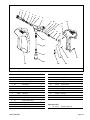
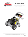
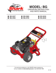
Figure 6 - Machine Assembly
Ref. No.
Part No. Description
Qty.
Ref. No.
Part No. Description
Qty.
1
375441
Chassis
1
22
817322
Hubcap
2
2
Fig. 9
Trigger Gun/Wand Assembly
1
23
848616
Push Nut 5/8"
2
3
444469
Decal Shark Detergent
1
24
■
Flat Washer 5/8"
4
4
Fig. 7
Pump Assembly
1
25
834154
Decal Winterize
1
5
859815
Grommet (Nozzle Holders)
5
26
919537
Engine Pulley
1
6
890783
Engine Warning Tag
1
27
815135
Engine Pulley Bushing
1
7
661261
Engine
1
28
877283
Engine Shaft Key
1
8
834180
Decal Beltguard
1
29
Bolt 8 mm x 16 mm
4
● ■
9
444462
Decal Caution Gasoline
1
30
615527
Bumper
2
10
258458
Beltguard
1
31
■
Flat Washer 3/8"
2
11
■
Flange Bolt 1/4" - 20 x 3/4"
3
32
■
Bolt 3/8" - 16 x 1"
2
12
826176
Quick Disconnect
1
33
646026
Decal Carbon Monoxide
1
13
707226
Pressure Hose
1
34
■
Lock Washer 5/16"
4
14
615494
Belt
2
35
646103
Decal Nozzle
1
15
■
Bolt 1/2" - 13 x 3-1/2"
1
36
630606
Clip
1
16
■
Flat Washer 1/2"
1
37
345063
Axle
1
375331
Belt Tensioning Bracket
1
38
915774
Quick Disconnect Plug
1
Bolt 5/16" - 18 x 1-3/4"
4
39
780451
Pump Mounting Washer
4
17
18
● ■
19
■
Flat Washer 5/16"
12
20
■
Locknut 5/16" - 18
8
■ Standard hardware item available locally.
21
983016
Wheel
2
● Use thread locking compound.
Page 10
Shark B2535H/1
1
2,3
4
8,9
10
11
5
6
7
9,16
15
14
13
12
Figure 7 - Pump Assembly
Ref. No.
Part No. Description
Qty.
Ref. No.
1
HC340R Pump Fig. 8
1
12
921421
Thermal Relief Valve
1
2
815202
Pump Pulley Bushing
1
13
856035
Garden Hose Connector Gasket
1
3
875446
Pump Pulley
1
14
801126
Garden Hose Connector
1
4
915774
Quick Disconnect Plug
1
15
875575
Garden Hose Connector Spring
1
5
640125
Relief Valve Cartridge
1
16
651485
Bolt Unloader Valve
1
6
784200
Relief Valve Manifold
1
7
875640
Relief Valve Seat
1
8
615541
Bolt Unloader Valve
1
Replacement Parts
9
936633
Flat Washer w/Seal
4
✪ 753025
O-Ring Repair Kit
1
921509
Unloader Valve
1
✪ 753026
Discharge Repair Kit
1
890769
Unloader Warning Tag
1
✪ 753027
Stem Repair Kit
1
10
11
✪
Shark B2535H/1
Part No. Description
Qty.
Page 11
Page 12
10 9
5
4
3
2
1
35
42
36 37 38
27
39
12
13
10
9
16
15
14
17
44
25
43
21
22
41
40
27
28 29 30 31 32 33 34
18
11
27
26
9
7 6 8 7 6
22 23 24 25
{
19
20
21
{
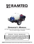
Figure 8 - Pump, Exploded View
Shark B2535H/1
Ref. No.
Part No. Description
Qty.
Ref. No.
Part No. Description
Qty.
1
630683
Crankcase
1
26
814210
Oil Dipstick
1
2
860361
Plunger Guide
3
27
855893
Gasket 3/8"
3
3
▼ ❖
Plunger Seal
3
28
✤
Plunger Nut
3
4
▼ ◆
Pressure Ring O-Ring
3
29
✤
Ceramic Sleeve 18 mm
3
5
▼
Pressure Ring 18 mm
3
30
✤
Copper Spacer
3
6
▼ ◆
V-Sleeve 18 mm
6
31
✤
Plunger Rod O-Ring
3
7
▼ ◆
Support Ring 18 mm
6
32
✤
Teflon Ring
3
8
▼
Intermediate Ring 18 mm
3
33
829669
Plunger Rod
3
9
915630
Plug 3/8"
3
34
860142
Connecting Rod Pin
3
10
780565
Copper Washer 3/8"
2
35
630688
Connecting Rod Assembly
3
11
783854
Manifold Housing
1
36
780564
Spring Washer
6
12
780560
Washer
8
37
878197
Allen Screw
6
13
875571
Manifold Stud Bolt
1
38
735313
Crankcase Cover Allen Screw
4
14
★
Valve Seat O-Ring
6
39
858431
Sight Glass 3/8"
1
15
★
Valve Seat
6
40
827324
Crankcase Cover
1
16
★
Valve Plate
6
41
855889
Crankcase Cover Gasket
1
17
★
Valve Spring
6
42
632000
Crankshaft
1
18
★
Valve Cage
6
43
877249
Pump Shaft Key
1
Manifold Plug O-Ring
6
44
632020
Crankshaft Seal
1
19
926657
20
823335
Manifold Plug
6
21
875572
Hex Screw
8
22
615488
Bearing Cover
2
23
615489
Bearing Protector w/o Sight Glass
1
▼
753106
878575
Sight Glass
1
◆
877672
Seal Packing Kit 18 mm
1
818575
O-Ring for Sight Glass
1
★
753039
Complete Valve Assembly Kit
6
24
860141
Crankshaft Snap Ring
1
✤
753107
Ceramic Sleeve Kit 18 mm
3
25
808895
Ball Bearing
2
❖
877655
Plunger Seal Kit
1
Shark B2535H/1
Replacement Parts
Qty/Pump
Complete Seal Packing Kit 18 mm
3
Page 13
1
2
3
4
3
5,6,7,8
9
Figure 9 - Trigger Gun/Wand Assembly
Ref. No.
Part No. Description
Qty.
Ref. No.
Part No. Description
Qty.
1
860447
Trigger Gun Fig. 10
1
6
799012
Pressure Nozzle (Yellow)
1
2
915786
Quick Disconnect Plug
1
7
799024
Pressure Nozzle (White)
1
3
826169
Quick Disconnect
2
8
799144
Pressure Nozzle (Green
1
9
826177
Quick Disconnect
1
4
936701
Wand
1
5
799000
Pressure Nozzle (Red)
1
Page 14
Shark B2535H/1
1
2
3
4
5
6
7
8
9
10
16
11
10
15
12
13
14
21
22
21
18
17
23
24
20
19
Figure 10 - Trigger Gun, Exploded View
Ref. No.
Part No. Description
1
817320
Valve Cap
Qty.
Ref. No.
1
15
Part No. Description
914141
Trigger Pin
Qty.
1
2
✪
Valve Cap O-Ring
1
16
860495
Left Gun Shell
1
3
✪
Valve Seat Spring
1
17
735316
Phillips Screw
6
4
✪
Valve Spring
1
18
914142
Trigger Lock Pin
1
5
✪
Ball
1
19
960271
Trigger
1
6
✪
Valve Seat
1
20
881941
Trigger Lock Lever
1
7
✪
Valve Seat O-Ring
1
21
936460
Inlet Pipe Seat
2
Valve Body
1
22
914285
Inlet Pipe
1
8
812801
9
✪
Plunger Guide Seat O-Ring
1
23
851190
Inlet Fitting
1
10
✪
Plunger Guide Backring
2
24
860496
Right Gun Shell
1
11
✪
Plunger Guide O-Ring
1
12
✪
Plunger Guide
1
13
✪
Plunger Rod
1
Replacement Parts
14
✪
Plunger Seat
1
✪ 877471
Shark B2535H/1
Trigger Gun Repair Kit
Page 15
WARRANTY
Shark
R
SHARK ONE-YEAR LIMITED WARRANTY:
Shark products are warranted by Shark Pressure Washers (Shark), to be free of defects in material and
workmanship under normal use, for a period of ONE YEAR from the date of the original purchase.
Items that fail due to normal wear such as pump seals, pump valves, unloader valves, detergent valves,
water nozzles, quick couplings, hoses, gunjets, o-rings, etc. are not covered under this warranty. Damage resulting from neglect, abuse, tampering, modification or misuse is not covered under this warranty. Shark will at its option repair or replace any part covered by this warranty which is defective under
normal use for one year at no charge for parts or labor. All defects must be verified by an authorized
Shark Pressure Washers service location.
EXCEPTIONS TO THE ONE YEAR WARRANTY FOR PARTS ONLY ARE:
Hawk Pumps: SEVEN YEAR Warranty (LIFETIME Brass Manifold WarrantyEven Against Freezing)
Heating Coils: FOUR YEAR Warranty
Chassis Assembly and Pulleys: THREE YEAR Warranty
Plumbing and Belts: TWO YEAR Warranty (This additional warranty will be in effect as
applicable.)
LIMITATION OF LIABILITY:
To the extent allowable under applicable law, Shark liability for consequential and incidental damages is
expressly disclaimed. Shark liability in all events is limited to, and shall not exceed, the purchase price
paid for the equipment. Shark liability excludes field labor charges, loss of use of the unit, loss of time
or rental, inconvenience, or commercial loss and is limited to repair or replacement of defective parts
only, at the option of Shark Pressure Washers.
WARRANTY DISCLAIMER:
Shark has made a diligent effort to illustrate and describe the product in this literature accurately;
however, such illustrations and descriptions are for the sole purpose of identification, and do not
express or imply a warranty that the product is merchantable, or fits a particular purpose, or that the
product will necessarily conform to the illustrations or descriptions.
PRODUCT SUITABILITY:
Many states and localities have codes and regulations governing sales, construction, installation, and/
or use of products for certain purposes, which may vary from those in neighboring areas. While
attempts to assure that its products comply with such codes, it cannot guarantee compliance, and
cannot be responsible for how the product is installed or used. Before purchase and use of a product,
please review the product application, and national and local codes and regulations, and be sure that
the product, installation, and use will comply with them.
PROMPT DISPOSITION:
Shark will make a good faith effort for prompt correction or other adjustments with respect to any
product which proves to be defective within limited warranty. For any product believed to be defective
within limited warranty, contact Shark Pressure Washers at 1-800-771-1881.
SHARK PRESSURE WASHERS
21 Inverness Way East
Englewood, Colorado 80112
1-800-771-1881
784623-6-97