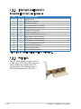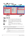
1
Motherboard
M2R-FVM
E2614
First Edition
May 2006
Copyright © 2006 ASUSTeK COMPUTER INC. All Rights Reserved.
No part of this manual, including the products and software described in it, may be reproduced,
transmitted, transcribed, stored in a retrieval system, or translated into any language in any form
or by any means, except documentation kept by the purchaser for backup purposes, without the
express written permission of ASUSTeK COMPUTER INC. (“ASUS”).
Product warranty or service will not be extended if: (1) the product is repaired, modified or
altered, unless such repair, modification of alteration is authorized in writing by ASUS; or (2) the
serial number of the product is defaced or missing.
ASUS PROVIDES THIS MANUAL “AS IS” WITHOUT WARRANTY OF ANY KIND, EITHER EXPRESS
OR IMPLIED, INCLUDING BUT NOT LIMITED TO THE IMPLIED WARRANTIES OR CONDITIONS OF
MERCHANTABILITY OR FITNESS FOR A PARTICULAR PURPOSE. IN NO EVENT SHALL ASUS,
ITS DIRECTORS, OFFICERS, EMPLOYEES OR AGENTS BE LIABLE FOR ANY INDIRECT, SPECIAL,
INCIDENTAL, OR CONSEQUENTIAL DAMAGES (INCLUDING DAMAGES FOR LOSS OF PROFITS, LOSS
OF BUSINESS, LOSS OF USE OR DATA, INTERRUPTION OF BUSINESS AND THE LIKE), EVEN IF ASUS
HAS BEEN ADVISED OF THE POSSIBILITY OF SUCH DAMAGES ARISING FROM ANY DEFECT OR
ERROR IN THIS MANUAL OR PRODUCT.
SPECIFICATIONS AND INFORMATION CONTAINED IN THIS MANUAL ARE FURNISHED FOR
INFORMATIONAL USE ONLY, AND ARE SUBJECT TO CHANGE AT ANY TIME WITHOUT NOTICE, AND
SHOULD NOT BE CONSTRUED AS A COMMITMENT BY ASUS. ASUS ASSUMES NO RESPONSIBILITY
OR LIABILITY FOR ANY ERRORS OR INACCURACIES THAT MAY APPEAR IN THIS MANUAL,
INCLUDING THE PRODUCTS AND SOFTWARE DESCRIBED IN IT.
Products and corporate names appearing in this manual may or may not be registered
trademarks or copyrights of their respective companies, and are used only for identification or
explanation and to the ownersʼ benefit, without intent to infringe.
ii
Contents
Notices ............................................................................................... vii
Safety information .............................................................................viii
About this guide .................................................................................. ix
M2R-FVM specifications summary ....................................................... xi
Chapter 1:
Product introduction
1.1
Welcome! .............................................................................. 1-1
1.2
Package contents ................................................................. 1-1
1.3
Special features .................................................................... 1-2
1.3.1
Product highlights ................................................... 1-2
1.3.2
Innovative ASUS features ...................................... 1-4
1.4
Before you proceed .............................................................. 1-5
1.5
Motherboard overview .......................................................... 1-6
1.6
1.7
1.8
1.5.1
Placement direction ................................................ 1-6
1.5.2
Screw holes ............................................................. 1-6
1.5.3
Motherboard layout ................................................ 1-7
1.5.4
Layout contents ..................................................... 1-8
Central Processing Unit (CPU) .............................................. 1-9
1.6.1
Installing the CPU .................................................... 1-9
1.6.2
Installing the heatsink and fan .............................. 1-11
System memory.................................................................. 1-14
1.7.1
Overview ............................................................... 1-14
1.7.2
Memory configurations ......................................... 1-15
1.7.3
Installing a DIMM ................................................... 1-16
1.7.4
Removing a DIMM .................................................. 1-16
Expansion slots ................................................................... 1-17
1.8.1
Installing an expansion card .................................. 1-17
1.8.2
Configuring an expansion card .............................. 1-17
1.8.3
Interrupt assignments ........................................... 1-18
1.8.4
PCI slots ................................................................ 1-18
1.8.5
PCI Express x1 slot ............................................... 1-19
1.8.6
PCI Express x16 slot ............................................. 1-19
iii
Contents
1.9
Jumpers .............................................................................. 1-20
1.10
Connectors ......................................................................... 1-23
1.10.1 Rear panel connectors .......................................... 1-23
1.10.2 Internal connectors ............................................... 1-24
Chapter 2:
2.1
2.2
2.3
iv
BIOS setup
Managing and updating your BIOS ........................................ 2-1
2.1.1
Creating a bootable floppy disk .............................. 2-1
2.1.2
ASUS EZ Flash 2 utility............................................ 2-2
2.1.3
Award BIOS Flash Utility .......................................... 2-3
2.1.4
Saving the current BIOS file .................................... 2-5
2.1.5
ASUS CrashFree BIOS 2 utility ................................ 2-6
BIOS setup program .............................................................. 2-7
2.2.1
BIOS menu screen ................................................... 2-8
2.2.2
Menu bar ................................................................. 2-8
2.2.3
Legend bar .............................................................. 2-9
2.2.4
Menu items ............................................................. 2-9
2.2.5
Sub-menu items ...................................................... 2-9
2.2.6
Configuration fields ................................................. 2-9
2.2.7
Pop-up window ...................................................... 2-10
2.2.8
General help .......................................................... 2-10
Main menu........................................................................... 2-11
2.3.1
System Time ........................................................ 2-11
2.3.2
System Date ......................................................... 2-11
2.3.3
Legacy Diskette A ............................................... 2-11
2.3.4
Primary IDE Master/Slave ...................................... 2-12
2.3.6
SATA1, 2, 3.........................................................................2-14
Contents
2.3.7
2.4
2.4.1
2.5
2.6
2.7
Installed Memory ................................................... 2-15
Advanced menu .................................................................. 2-15
JumperFree Configuration ..................................... 2-16
2.4.2
Chipset .................................................................. 2-16
2.4.3
PCIPnP ................................................................... 2-18
2.4.4
Onboard Device Configuration .............................. 2-20
Power menu ........................................................................ 2-23
2.5.1
ACPI Suspend Type ............................................... 2-23
2.5.2
ACPI APIC Support ................................................ 2-23
2.5.3
APM Configuration ................................................ 2-24
2.5.4
Hardware Monitor.................................................. 2-25
Boot menu .......................................................................... 2-26
2.6.1
Boot Device Priority .............................................. 2-26
2.6.2
Boot Settings Configuration ................................ 2-27
2.6.3
Security ................................................................. 2-28
Exit menu ............................................................................ 2-29
v
Notices
Federal Communications Commission Statement
This device complies with Part 15 of the FCC Rules. Operation is subject to
the following two conditions:
• This device may not cause harmful interference, and
• This device must accept any interference received including
interference that may cause undesired operation.
This equipment has been tested and found to comply with the limits for a
Class B digital device, pursuant to Part 15 of the FCC Rules. These limits
are designed to provide reasonable protection against harmful interference
in a residential installation. This equipment generates, uses and can radiate
radio frequency energy and, if not installed and used in accordance with
manufacturerʼs instructions, may cause harmful interference to radio
communications. However, there is no guarantee that interference will
not occur in a particular installation. If this equipment does cause harmful
interference to radio or television reception, which can be determined by
turning the equipment off and on, the user is encouraged to try to correct
the interference by one or more of the following measures:
• Reorient or relocate the receiving antenna.
• Increase the separation between the equipment and receiver.
• Connect the equipment to an outlet on a circuit different from that to
which the receiver is connected.
• Consult the dealer or an experienced radio/TV technician for help.
The use of shielded cables for connection of the monitor to the graphics
card is required to assure compliance with FCC regulations. Changes
or modifications to this unit not expressly approved by the party
responsible for compliance could void the userʼs authority to operate
this equipment.
Canadian Department of Communications Statement
This digital apparatus does not exceed the Class B limits for radio noise
emissions from digital apparatus set out in the Radio Interference
Regulations of the Canadian Department of Communications.
This class B digital apparatus complies with Canadian ICES-003.
vi
Safety information
Electrical safety
• To prevent electrical shock hazard, disconnect the power cable from
the electrical outlet before relocating the system.
• When adding or removing devices to or from the system, ensure that
the power cables for the devices are unplugged before the signal
cables are connected. If possible, disconnect all power cables from the
existing system before you add a device.
• Before connecting or removing signal cables from the motherboard,
ensure that all power cables are unplugged.
• Seek professional assistance before using an adpater or extension
cord. These devices could interrupt the grounding circuit.
• Make sure that your power supply is set to the correct voltage in your
area. If you are not sure about the voltage of the electrical outlet you
are using, contact your local power company.
• If the power supply is broken, do not try to fix it by yourself. Contact
a qualified service technician or your retailer.
Operation safety
• Before installing the motherboard and adding devices on it, carefully
read all the manuals that came with the package.
• Before using the product, make sure all cables are correctly connected
and the power cables are not damaged. If you detect any damage,
contact your dealer immediately.
• To avoid short circuits, keep paper clips, screws, and staples away from
connectors, slots, sockets and circuitry.
• Avoid dust, humidity, and temperature extremes. Do not place the
product in any area where it may become wet.
• Place the product on a stable surface.
• If you encounter technical problems with the product, contact a
qualified service technician or your retailer.
vii
About this guide
This user guide contains the information you need when installing and
configuring the motherboard.
How this guide is organized
This guide contains the following parts:
•
Chapter 1: Product introduction
This chapter describes the features of the motherboard and the
new technology it supports. This chapter also lists the hardware
setup procedures that you have to perform when installing system
components. It includes description of the switches, jumpers, and
connectors on the motherboard.
•
Chapter 2: BIOS setup
This chapter tells how to change system settings through the BIOS
Setup menus. Detailed descriptions of the BIOS parameters are also
provided.
Where to find more information
Refer to the following sources for additional information and for product
and software updates.
1.
ASUS websites
The ASUS website provides updated information on ASUS hardware
and software products. Refer to the ASUS contact information.
2.
Optional documentation
Your product package may include optional documentation, such as
warranty flyers, that may have been added by your dealer. These
documents are not part of the standard package.
viii
Conventions used in this guide
To make sure that you perform certain tasks properly, take note of the
following symbols used throughout this manual.
DANGER/WARNING: Information to prevent injury to yourself
when trying to complete a task.
CAUTION: Information to prevent damage to the components
when trying to complete a task.
IMPORTANT: Instructions that you MUST follow to complete a
task.
NOTE: Tips and additional information to help you complete a
task.
Typography
Bold text
Indicates a menu or an item to select.
Italics
Used to emphasize a word or a phrase.
<Key>
Keys enclosed in the less-than and greater-than
sign means that you must press the enclosed key.
Example: <Enter> means that you must press the
Enter or Return key.
<Key1>+<Key2>+<Key3>If you must press two or more keys
simultaneously, the key names are connected
with a plus sign (+).
Example: <Ctrl>+<Alt>+<Del>
Command
Means that you must type the command exactly
as shown, then supply the required item or value
enclosed in brackets.
Example: At the DOS prompt, type the command
line:
afudos /i[filename]
afudos /iM2R-FVM.bin
ix
M2R-FVM specifications summary
CPU
Socket AM2 for AMD Athlon™ 64 X2 /AMD Athlon™ 64
/AMD Sempron™ processors
Supports AMD Cool ‘n’ Quiet™ Technology
AMD64 architecture enables simultaneous 32-bit and
64-bit computing
Chipset
ATI® RS485
ATI® SB600
HT Frequency
800 MHz /1GHz
Memory
Dual-channel memory architecture
- 4 x 240-pin DIMM sockets support unbuffered
DDR2 667/533 MHz memory modules
- Supports up to 2GB system memory with dualchannel memory
Expansion slots
1 x PCI Express™ x16 slots
1 x PCI Express™ x1 slots
2 x PCI 2.2 slots
Storage
South Bridge SB600 supports:
- 1 x IDE connector for up to two Ultra DMA
133/100/66/33 devices
- 4 x Serial ATA connectors support four
Serial ATA devices
- RAID 0, RAID1 and RAID 0+1founctions
Audio
Realtek® ALC883 8-channel Azalia CODEC
Supports Jack-Sensing & Enumeration Technology
Supports S/PDIF out interface
IEEE 1394
T1 1394 controller supports:
- 1 x IEEE 1394a connector
USB
Supports up to 8 USB 2.0/1.1 ports
Form factor
uATX form factor: 9.6 in x 9.6 in (24.5 cm x 24.5 cm)
LAN
Realtek® RTL8100C 10/100M LAN controller
Special features
Rear panel
-
ASUS CrashFree BIOS 2
ASUS EZ Flash
ASUS Q-fan1.5
ASUS MyLogo2
Dram Burnt proof
1 x Serial (COM1) port
1 x VGA port
1 x S/PDIF Out port
1 x 1394 port
1 x LAN (RJ-45) port
4 x USB 2.0/1.1 ports
8-channel audio ports
(continued on the next page)
x
M2R-FVM specifications summary
Internal connectors
4 x USB 2.0 connectors
1 x Floppy disk drive connector
1 x IDE connector for two devices
4 x Serial ATA connectors
1 x CPU / 1 x Chassis fan connectors
1 x IEEE 1394a connector
1 x S/PDIF Out connector
Front panel audio connector
AUX audio in connector
24-pin ATX power connector
4-pin ATX 12 V power connector
System panel connector
BIOS features
4 Mb AWARD BIOS, PnP, DMI, WfM2.0, ACPI 2.0c,
SM BIOS 2.3, CrashFree BIOS2, EZ Flash,
Special H/W write protection
Manageability
WOR by Ring, WOL by PME, WOR by PME,
Wake on USB from S1, S3, S4
Power requirements
ATX power supply (with 24-pin and 4-pin 12 V plugs)
ATX 12 V 2.0 compliant
Drivers
Chipset update driver
On-board graphic driver
Bus master IDE driver
RAID driver
Audio driver
LAN driver
AMD AWAY mode driver
Utilities & Applications
BIOS flash utility under DOS
ASUS Update - BIOS
AMD Cool’n Quiet Utility
*Specifications are subject to change without notice.
xi
This chapter describes the motherboard
features and the new technologies
it supports.
1
Product
introduction
1.1
Welcome!
Thank you for buying an ASUS® M2R-FVM motherboard!
The motherboard delivers a host of new features and latest technologies, making it
another standout in the long line of ASUS quality motherboards!
Before you start installing the motherboard, and hardware devices on it, check the
items in your package with the list below.
ASUS M2R-FVM
1-1
1.3
Special features
1.3.1
Product highlights
Latest processor technology
The motherboard comes with a 940-pin AM2 socket that supports AMD Athlon™
64 X2/AMD Athlon™ 64/AMD Sempron™ processor. With an integrated lowlatency high-bandwidth memory controller and a highly scalable HyperTransport™
technology-based system bus, the motherboard provides a powerful platform for
your diverse computing needs, increased office productivity, and enhanced digital
media experience.
DDR2 memory support
The motherboard supports DDR2 memory that features data transfer rates of
667/533 MHz to meet the higher bandwidth requirements of the latest 3D graphics,
multimedia, and Internet applications. The dual-channel DDR2 architecture
doubles the bandwidth of your system memory to boost system performance and
eliminating bottlenecks.
PCI Express™ interface
The motherboard fully supports PCI Express, the latest I/O interconnect technology
that speeds up the PCI bus. PCI Express features point-to-point serial
interconnections between devices and allows higher clockspeeds by carrying data
in packets. This high speed interface is software compatible with existing PCI
specifications.
Serial ATA technology with RAID function
The motherboard supports the Serial ATA technology through the Serial ATA
interfaces and the SB600 Southbridge. Serial ATA allows for thinner, more flexible
cables with lower pin count, reduced voltage requirement, and data transfer rates
of up to 150 MB/s for SATA I and 300 MB/s for SATA II.
The SB600 built-in RAID function supports RAID 0, RAID 1 and RAID 0+1
configuration for four SATA and one IDE connectors and allows you to select the
best RAID solution using IDE or Serial ATA devices.
1-2
Chapter 1: Product introduction
IEEE 1394a support
The IEEE 1394a interface provides high-speed and flexible PC connectivity to
a wide range of peripherals and devices compliant to the IEEE 1394a standard.
The IEEE 1394a interface allows up to 400 Mbps transfer rates through simple,
low-cost, high-bandwidth asynchronous (real-time) data interfacing between
computers, peripherals, and consumer electronic devices such as camcorders,
VCRs, printers, TVs, and digital cameras.
S/PDIF digital sound ready
The motherboard supports the S/PDIF technology through the S/PDIF interfaces
on the rear panel. The S/PDIF technology turns your computer into a high-end
entertainment system with digital connectivity to powerful audio and speaker
systems.
USB 2.0 technology
The motherboard implements the Universal Serial Bus (USB) 2.0 specification,
dramatically increasing the connection speed from the 12 Mbps bandwidth on USB
1.1 to a fast 480 Mbps on USB 2.0. USB 2.0 is backward compatible with USB 1.1.
AMD Cool ‘n’ Quiet Technology
The motherboard supports the AMD Cool ‘n’ Quiet Technology, which monitors
system operation and automatically adjusts CPU voltage and frequency for a cool
and quiet operating environment.
ASUS M2R-FVM
1-3
1.3.2
Innovative ASUS features
ASUS CrashFree BIOS 2
This feature allows you to restore the original BIOS data in case when the BIOS
codes and data are corrupted. This protection eliminates the need to buy a
replacement ROM chip.
ASUS EZ Flash BIOS
With the ASUS EZ Flash, you can easily update the system BIOS even before
loading the operating system.
ASUS Q-Fan technology
The ASUS Q-Fan technology smartly adjusts the CPU fan speed according to the
system loading to ensure quiet, cool, and efficient operation.
1-4
Chapter 1: Product introduction
1.4
Before you proceed
Take note of the following precautions before you install motherboard
components or change any motherboard settings.
•
Unplug the power cord from the wall socket before touching any
component.
•
Use a grounded wrist strap or touch a safely grounded object or to
a metal object, such as the power supply case, before handling
components to avoid damaging them due to static electricity.
•
Hold components by the edges to avoid touching the ICs on them.
•
Whenever you uninstall any component, place it on a grounded
antistatic pad or in the bag that came with the component.
•
Before you install or remove any component, ensure
that the ATX power supply is switched off or the power cord is
detached from the power supply. Failure to do so may cause severe
damage to the motherboard, peripherals, and/or components.
Onboard LED
The motherboard comes with a standby power LED. The green LED
lights up to indicate that the system is ON, in sleep mode, or in
soft-off mode. This is a reminder that you should shut down the
system and unplug the power cable before removing or plugging
in any motherboard component. The illustration below shows the
location of the onboard LED.
SB_PWR
R
M2R-FVM
ON
Standby
Power
OFF
Powered
Off
M2R-FVM Onboard LED
ASUS M2R-FVM
1-5
1.5
Motherboard overview
Before you install the motherboard, study the configuration of your chassis
to ensure that the motherboard fits into it.
Make sure to unplug the power cord before installing or removing the
motherboard. Failure to do so can cause you physical injury and damage
motherboard components.
1.5.1
Placement direction
When installing the motherboard, make sure that you place it into the
chassis in the correct orientation. The edge with external ports goes to the
rear part of the chassis as indicated in the image below.
1.5.2
Screw holes
Place nine (9) screws into the holes indicated by circles to secure the
motherboard to the chassis.
Do not overtighten the screws! Doing so can damage the motherboard.
Place this side towards
the rear of the chassis
R
M2R-FVM
1-6
Chapter 1: Hardware information
F_AUDIO1
PCI2
ALC883
PCIEX1
AUX1
ASUS M2R-FVM
IE1394_2
TSB43AB22A
USBPW56
USBPW78
USB56
USB78
M2R-FVM
CR2032 3V
Lithium Cell
CMOS Power
ATI SB600
PASSWORD_S
BIOS_R
R
CLRTC
SB_PWR
PCIEX16
IDE1
SATA1
PCI1
SATA2
LAN_USB34
Socket AM2
USBPW34
USBPW12
ATI RS485
24.5cm (9.6in)
FLOPPY1
ATXPWR1
COM1
Super I/O
DDR2 DIMM_B2 (128 bit,240-pin module)
DDR2 DIMM_A2 (128 bit,240-pin module)
DDR2 DIMM_B1 (128 bit,240-pin module)
DDR2 DIMM_A1 (128 bit,240-pin module)
F_USB12
SATA3
AUDIO1
SPDIF_OUT
SPDIF_O2
SATA4
RTL8100C
VGA1
1.5.3
Motherboard layout
ATX12V1
24.5cm (9.6in)
CPU_FAN CHA_FAN1
4Mb
BIOS
BUZZ1
F_PANEL1
1-7
1.5.4
Slots
1.
2.
3.
4.
Jumpers
1.
2.
3.
4.
Layout contents
Page
1-15
1-19
1-20
1-20
DDR2 DIMM slots
PCI slots
PCI Express x 1 slots
PCI Express x16 slots
Page
1-21
1-23
1-22
1-22
Clear RTC RAM (3-pin CLRTC1)
USB Power (3-pin USBPW12, 34, 56, 78)
Password Skip (3-pin PASSWORD_s)
BIOS Recovery (3-pin BIOS_R)
Rear panel connectors
1.
Serial (COM1) port
2.
VGA port
3.
S/PDIF Out port
4.
LAN (RJ-45) port.
5.
IEEE 1394a port.
6.
USB 2.0 ports 1 and 2, 3 and 4
7.
Center/Subwoofer port (orange)
8.
Rear Speaker Out port (black)
9.
Line In port (light blue)
10.
Line Out port (lime)
11.
Microphone port (pink)
12.
Side Speaker Out port (grey)
Internal connectors
1.
Floppy disk drive connector (34-1 pin FLOPPY)
2.
IDE connector (40-1 pin PRI_IDE)
3.
Serial ATA connectors (7-pin SATA1, SATA2, SATA3, SATA4)
5.
USB connectors (10-1 pin USB56, USB78)
6.
IEEE 1394a port connector (10-1 pin IE1394_2)
7.
CPU and chassis fan connectors
(4-pin CPU_FAN, 4-pin CHA_FAN1)
8.
ATX power connectors (24-pin EATXPWR, 4-pin EATX12V)
9.
Front panel audio connector (10-1 pin F_AUDIO1)
10.
Internal audio connector (4-pin AUX1)
11.
Digital audio connector (3-pin SPDIF_OUT)
12.
System panel connector (10-1 pin F_PANEL1)
•
•
•
•
1-8
Page
1-25
1-25
1-25
1-24
1-24
1-25
1-24
1-24
1-24
1-24
1-24
1-24
Page
1-25
1-26
1-27
1-29
1-30
1-28
1-28
1-30
1-29
1-27
1-31
System power LED (Green 2-pin PWR_LED)
Hard disk drive activity LED (Red 2-pin HD_LED)
ATX power button/soft-off button (Black 2-pin PWR_BTN)
Reset button (Blue 2-pin RESET)
Chapter 1: Hardware information
1.6
Central Processing Unit (CPU)
The motherboard comes with a 940-pin AM2 socket designed for the AMD
Athlon™ 64 X2/Athlon™ 64/Sempron™ processor.
The AM2 socket has a different pinout from the 940-pin socket designed
for the AMD Opteron™ processor. Make sure you use a CPU is designed
for the AM2 socket. The CPU fits in only one correct orientation. DO NOT
force the CPU into the socket to prevent bending the connectors on the
socket and damaging the CPU!
1.6.1
Installing the CPU
To install a CPU:
1.
Locate the CPU socket on the motherboard.
R
M2R-FVM
M2R-FVM CPU Socket AM2
2.
Unlock the socket by pressing
the lever sideways, then lift it up
to a 90º angle.
Socket lever
Make sure that the socket lever is lifted up to a 90º angle; otherwise,
the CPU will not fit in completely.
ASUS M2R-FVM
1-9
3.
Position the CPU above the
socket such that the CPU corner
with the gold triangle matches
the socket corner with a small
triangle.
4.
Carefully insert the CPU into the
socket until it fits in place.
Please make sure
your CPU is fully
Gold triangle
plugged-in to reduce
abnormal symptom.
Small triangle
1-10
5.
When the CPU is in place, push
down the socket lever to secure
the CPU. The lever clicks on the
side tab to indicate that it is
locked.
6.
Install a CPU heatsink and fan
following the instructions that
came with the heatsink package.
Chapter 1: Hardware information
1.6.2
Installing the heatsink and fan
The AMD Athlon™ 64/AMD Athlon™ 64 X2/ AMD Sempron™ processor
requires a specially designed heatsink and fan assembly to ensure optimum
thermal condition and performance.
Make sure that you use only AMD-certified heatsink and fan assembly.
Follow these steps to install the CPU heatsink and fan.
1.
Place the heatsink on top of the installed CPU, making sure that the
heatsink fits properly on the retention module base.
•
The retention module base is already installed on the motherboard
upon purchase.
•
You do not have to remove the retention module base when
installing the CPU or installing other motherboard components.
•
If you purchased a separate CPU heatsink and fan assembly, make
sure that a Thermal Interface Material is properly applied to the CPU
heatsink or CPU before you install the heatsink and fan assembly.
CPU Fan
CPU Heatsink
Retention bracket
Retention Module Base
Retention bracket lock
Your boxed CPU heatsink and fan assembly should come with installation
instructions for the CPU, heatsink, and the retention mechanism. If the
instructions in this section do not match the CPU documentation, follow
the latter.
ASUS M2R-FVM
1-11
2.
Attach one end of the retention bracket to the retention module base.
1
2
3
3.
4
5
Align the other end of the retention bracket (near the retention
bracket lock) to the retention module base. A clicking sound denotes
that the retention bracket is in place.
Make sure that the fan and heatsink assembly perfectly fits the
retention mechanism module base, otherwise you cannot snap the
retention bracket in place.
4.
Push down the retention bracket lock on the retention mechanism to
secure the heatsink and fan to the module base.
5.
When the fan and heatsink assembly is in place, connect the CPU fan
cable to the connector on the motherboard labeled CPU_FAN.
Do not forget to connect the CPU fan connector! Hardware monitoring
errors can occur if you fail to plug this connector.
1-12
Chapter 1: Hardware information
5.
When the fan and heatsink assembly is in place, connect the CPU fan
cable to the connector on the motherboard labeled CPU_FAN.
CPU_FAN
CPU FAN PWM
CPU FAN IN
CPU FAN PWR
GND
R
M2R-FVM
M2R-FVM CPU Fan Connector
Do not forget to connect the CPU fan connector! Hardware monitoring
errors can occur if you fail to plug this connector.
ASUS M2R-FVM
1-13
1.7
System memory
1.7.1
Overview
The motherboard comes with four Double Data Rate 2 (DDR2) Dual Inline
Memory Modules (DIMM) sockets.
A DDR2 module has the same physical dimensions as a DDR DIMM but has
a 240-pin footprint compared to the 184-pin DDR DIMM. DDR2 DIMMs are
notched differently to prevent installation on a DDR DIMM socket.
128 Pins
DIMM_A2
DIMM_B2
DIMM_A1
DIMM_B1
The figure illustrates the location of the DDR2 DIMM sockets:
112 Pins
R
M2R-FVM
M2R-FVM 240-pin DDR2 DIMM Sockets
Channel
Channel A
Channel B
1-14
Sockets
DIMM_A1/DIMM_A2
DIMM_B1/DIMM_B2
Chapter 1: Hardware information
1.7.2
Memory configurations
You may install 256 MB, 512 MB, and 1 GB unbuffered ECC/non-ECC DDR2
DIMMs into the DIMM sockets.
•
For dual-channel configuration, the total size of memory module(s)
installed per channel must be the same (DIMM_A1 + DIMM_A2 =
DIMM_B1 + DIMM_B2).
•
Always install DIMMs with the same CAS latency. For optimum
compatibility, we recommend that you obtain memory modules from
the same vendor. Visit the ASUS website (www.asus.com) for the
latest Qualified Vendors List.
•
When using only one DDR DIMM module, install it into slot DIMM_B2
only.
•
For single-channel memory configuration, start installing the DDR2
DIMMs from slot DIMM_B1 or DIMM_B2.
•
For dual-channel memory configuration, install the DIMMs in slots
DIMM_B2 and DIMM_A2 (black); install another pair of DIMMs in slots
DIMM_B1 and DIMM_A1 (yellow).
Important notice on installing Windows® XP 32-bit version
If you install Windows® XP 32-bit version Operating System (OS), the
limitation of this OS version is that it may reserve a certain amount of
memory space for system devices. We recommend that you install less
than 3 GB system memory if you would like to work under Windows® XP
32-bit version OS. The excess memory installation will not cause any
usage problem, but it will not give users the benefit of manipulating this
excess memory space.
Visit the ASUS FAQ site for further
explanation:
http://support.asus.com/faq/faq.
aspx?SLanguage=en-us
Under General Search, make the
selections as shown, then click Search. Click the article titled “4GB
memory installed but less memory size detected.”
You also may check the URLs below for third party comments on this
issue:
http://dlsvr01.asus.com/pub/ASUS/mb/4GB_Rev1.pdf
http://www.intel.com/support/motherboards/server/sb/cs-016594.htm
ASUS M2R-FVM
1-15
1.7.3
Installing a DIMM
Unplug the power supply before adding or removing DIMMs or other
system components. Failure to do so can cause severe damage to both
the motherboard and the components.
2
To install a DIMM:
1.
Unlock a DIMM socket by
pressing the retaining clips
outward.
2.
Align a DIMM on the socket
such that the notch on the
DIMM matches the break on
the socket.
3.
3
DDR2 DIMM notch
1
Firmly insert the DIMM into
the socket until the retaining
clips snap back in place and
the DIMM is properly seated.
Unlocked retaining clip
1.7.4
•
A DDR2 DIMM is keyed with a notch so that it fits in only one
direction. Do not force a DIMM into a socket to avoid damaging the
DIMM.
•
The DDR2 DIMM sockets do not support DDR DIMMs. DO not install
DDR DIMMs to the DDR2 DIMM sockets.
Removing a DIMM
To remove a DIMM:
1.
Support the DIMM lightly with
your fingers when pressing
the retaining clips. The DIMM
might get damaged when it
flips out with extra force.
2.
1-16
2
Simultaneously press the
retaining clips outward to unlock
the DIMM.
1
1
DDR2 DIMM notch
Remove the DIMM from the socket.
Chapter 1: Hardware information
1.8
Expansion slots
In the future, you may need to install expansion cards. The following
sub-sections describe the slots and the expansion cards that they support.
Make sure to unplug the power cord before adding or removing
expansion cards. Failure to do so may cause you physical injury and
damage motherboard components.
1.8.1
Installing an expansion card
To install an expansion card:
1.
Before installing the expansion card, read the documentation that
came with it and make the necessary hardware settings for the card.
2.
Remove the system unit cover (if your motherboard is already
installed in a chassis).
3.
Remove the bracket opposite the slot that you intend to use. Keep
the screw for later use.
4.
Align the card connector with the slot and press firmly until the card is
completely seated on the slot.
5.
Secure the card to the chassis with the screw you removed earlier.
6.
Replace the system cover.
1.8.2
Configuring an expansion card
After installing the expansion card, configure the it by adjusting the
software settings.
1.
Turn on the system and change the necessary BIOS settings, if any.
See Chapter 2 for information on BIOS setup.
2.
Assign an IRQ to the card. Refer to the tables on the next page.
3.
Install the software drivers for the expansion card.
When using PCI cards on shared slots, ensure that the drivers support
“Share IRQ” or that the cards do not need IRQ assignments; otherwise,
conflicts will arise between the two PCI groups, making the system
unstable and the card inoperable.
ASUS M2R-FVM
1-17
1.8.3
Interrupt assignments
Standard interrupt assignments
IRQ
0
1
2
4
5
6
7
8
9
10
11
12
13
14
15
Priority
1
2
–
12
13
14
15
3
4
5
6
7
8
9
10
Standard function
System Timer
Keyboard Controller
Redirect to IRQ#9
Communications Port (COM1)*
IRQ Holder for PCI Steering*
Floppy Disk Controller
Printer Port (LPT1)*
System CMOS/Real Time Clock
IRQ Holder for PCI Steering*
IRQ Holder for PCI Steering*
IRQ Holder for PCI Steering*
PS/2 Compatible Mouse Port*
Numeric Data Processor
Primary IDE Channel
Secondary IDE Channel
* These IRQs are usually available for ISA or PCI devices.
1.8.4
PCI slots
The PCI slots support cards such as
a LAN card, SCSI card, USB card, and
other cards that comply with PCI
specifications. The figure shows a
LAN card installed on a PCI slot.
1-18
Chapter 1: Hardware information
1.8.5
PCI Express x1 slot
This motherboard supports PCI
Express x1 network cards, SCSI cards
and other cards that comply with the
PCI Express specifications. The figure
shows a network card installed on the
PCI Express x 1 slot.
1.8.6
PCI Express x16
slot
This motherboard supports PCI Express
x16 graphics cards that comply with
the PCI Express specifications. The
figure shows a graphics card installed
on the PCI Express x 16 slot.
ASUS M2R-FVM
1-19
1.9
Jumpers
Clear RTC RAM (CLRTC)
This jumper allows you to clear the Real Time Clock (RTC) RAM in
CMOS. You can clear the CMOS memory of date, time, and system
setup parameters by erasing the CMOS RTC RAM data. The onboard
button cell battery powers the RAM data in CMOS, which include
system setup information such as system passwords.
To erase the RTC RAM:
1. Turn OFF the computer and unplug the power cord.
2. Remove the onboard battery.
3. Move the jumper cap from pins 1-2 (default) to pins 2-3. Keep the
cap on pins 2-3 for about 5~10 seconds, then move the cap back
to pins 1-2.
4. Reinstall the battery.
5. Plug the power cord and turn ON the computer.
6. Hold down the <Del> key during the boot process and enter BIOS
setup to re-enter data.
Except when clearing the RTC RAM, never remove the cap on CLRTC
jumper default position. Removing the cap will cause system boot failure!
CLRTC
R
M2R-FVM
1 2
Normal
(Default)
2 3
Clear CMOS
M2R-FVM Clear RTC RAM
1-20
•
Make sure to re-enter your previous BIOS settings after you clear the
CMOS.
•
You do not need to clear the RTC when the system hangs due to
overclocking. For system failure due to overclocking, use the C.P.R.
(CPU Parameter Recall) feature. Shut down and reboot the system
so the BIOS can automatically reset parameter settings to default
values.
Chapter 1: Hardware information
BIOS Recovery (3-pin BIOS_R)
This jumper allows you to recover your original BIOS from a floppy disk
in case the BIOS codes and data are corrupted.
To recover the BIOS:
1. Turn OFF your computer and unplug the power cord.
2. Move the jumper cap from pins 1-2 (default) to pins 2-3.
3. Insert a floppy disk with the original or updated BIOS file.
4. Plug the power cord and turn ON the computer.
5. The system searches for the BIOS file in the floppy then reflashes
the BIOS.
6. When finished, shut down your computer.
7. Replace the jumper cap from pins 2-3 to pins 1-2.
8. Reboot your computer.
9. Hold down the <Del> key during the boot process and enter BIOS
setup to re-enter data.
BIOS_R
3
2
1
R
M2R-FVM
2
Normal
(Default)
BIOS Recovery
M2R-FVM BIOS Recovery
Password Skip (3-pin PASSWORD_S)
When the jumper cap is moved from 1-2 pin to 2-3 pin, the BIOS
password function will be skipped and users will not need a password
to enter into the BIOS.
PASSWORD_S
R
M2R-FVM
2
1
Normal
(Default)
3
2
Password Skip
M2R-FVM Password Skip
ASUS M2R-FVM
1-21
USB device wake-up (3-pin USBPW12, USBPW34, USBPW56,
USBPW78)
Set these jumpers to +5V to wake up the computer from S1 sleep
mode (CPU stopped, DRAM refreshed, system running in low power
mode) using the connected USB devices, Set to +5VSB to wake up
from S3 and S4 sleep modes (no power to CPU, DRAM in slow refresh,
power supply in reduced power mode)
The USBPWR12 and USBPWR34 jumpers are for the rear USB ports.
The USBPWR56 and USBPWR78 jumper is for the internal USB
connectors that you can connect to additional USB ports
1 2
2 3
USBPW12
USBPW34
+5V
R
M2R-FVM
USBPW56
USBPW78
1 2
M2R-FVM USB Device Wake Up
1-22
+5VSB
(Default)
+5V
2 3
+5VSB
(Default)
•
The USB device wake-up feature requires a power supply that can
provide 500mA on the +5VSB lead for each USB port; otherwise, the
system would not power up.
•
The total current consumed must NOT exceed the power supply
capability (+5VSB) whether under normal condition or in sleep mode.
Chapter 1: Hardware information
1.10
Connectors
1.10.1 Rear panel connectors
1
2
34
5
6
7
13
12
11
10
9
8
1.
IEEE 1394 port. This 6-pin IEEE 1394 port provides high-speed
connectivity for audio/vidoe, storage peripherals, PCs, or portable
devices.
2.
LAN (RJ-45) port. This port allows Gigabit connection to a Local
Area Network (LAN) through a network hub. Refer to the table below
for the LAN port LED indications.
3.
Rear Speaker Out port (Black). This port connects the rear
speakers on a 4-channel, 6-channel, or 8-channel audio configuration.
LAN port LED indications
ACT/LINK LED
SPEED LED
Status
Description
Status
Description
OFF
No link
OFF
10 Mbps connection
BLINKING
Data activity
GREEN
100Mbps connection
ACT/LINK SPEED
LED
LED
LAN port
4.
Center/Subwoofer port (orange). This port connects the
center/subwoofer speakers.
5.
Line In port (light blue). This port connects a tape, CD, DVD
player, or other audio sources.
6.
Line Out port (lime). This port connects a headphone or a
speaker. In 4-channel, 6-channel, and 8-channel configuration, the
function of this port becomes Front Speaker Out.
7.
Microphone port (pink). This port connects a microphone.
8.
Side Speaker Out port (grey). This port connects the side
speakers in an 8-channel audio configuration.
ASUS M2R-FVM
1-23
Refer to the audio configuration table below for the function of the audio
ports in 2, 4, or 6-channel configuration.
Audio 2, 4, 6 or 8-channel configuration
Port
2-channel
(Headset)
Light Blue
4-channel
6-channel
8-channel
Line In
Line In
Line In
Line In
Lime
Line Out
Front Speaker Out
Front Speaker Out
Front Speaker Out
Pink
Mic In
Mic In
Mic In
Mic In
Orange
—
Center /Subwoofer
Rear Speaker Out
Center/Subwoofer
Black
—
—
—
Rear Speaker Out
Gray
—
—
Side speaker out
Side speaker out
9.
USB 2.0 ports 3 and 4. These two 4-pin Universal Serial Bus (USB)
ports are available for connecting USB 2.0 devices.
10. USB 2.0 ports 1 and 2. These two 4-pin Universal Serial Bus (USB)
ports are available for connecting USB 2.0 devices.
11. SPDIF port. This port connectors an external audio output device via
a S/PDIF cable.
12. VGA port. This 15-pin VGA port connects to a VGA monitor.
13. Serial connector. This 9-pin COM1 port is for serial devices.SPDIF
port.
1.10.2 Internal connectors
1.
Floppy disk drive connector (34-1 pin FLOPPY1)
This connector is for the provided floppy disk drive (FDD) signal cable.
Insert one end of the cable to this connector, then connect the other
end to the signal connector at the back of the floppy disk drive.
Pin 5 on the connector is removed to prevent incorrect cable connection
when using an FDD cable with a covered Pin 5.
FLOPPY
R
M2R-FVM
PIN 1
NOTE: Orient the red markings on
the floppy ribbon cable to PIN 1.
M2R-FVM Floppy Disk Drive Connector
1-24
Chapter 1: Product introduction
2.
IDE connector (40-1 pin IDE1)
These connectors are for Ultra DMA 133/100/66 signal cables.
The Ultra DMA 133/100/66 signal cable has three connectors: a
blue connector for the primary IDE connector on the motherboard,
a black connector for an Ultra DMA 133/100/66 IDE slave device
(optical drive/hard disk drive), and a gray connector for an Ultra
DMA 133/100/66 IDE master device (hard disk drive). If you install
two hard disk drives, you must configure the second drive as a slave
device by setting its jumper accordingly. Refer to the hard disk
documentation for the jumper settings.
•
Pin 20 on the IDE connector is removed to match the covered hole
on the Ultra DMA cable connector. This prevents incorrect insertion
when you connect the IDE cable.
•
Use the 80-conductor IDE cable for Ultra DMA 100/66 IDE devices.
IDE1
NOTE: Orient the red markings
(usually zigzag) on the ID
ribbon cable to PIN 1.
R
M2R-FVM
M2R-FVM IDE Connector
ASUS M2R-FVM
PIN 1
1-25
3.
Serial ATA connectors (7-pin SATA1, SATA2, SATA3,
SATA4)
These connectors are for the Serial ATA signal cables for Serial ATA
hard disk drives. The current Serial ATA I interface allows up to 150
MB/s data transfer rate.
SATA1
SATA3
GND
RSATA_TXP1
RSATA_TXN1
GND
RSATA_RXP1
RSATA_RXN1
GND
GND
RSATA_TXP2
RSATA_TXN2
GND
RSATA_RXP2
RSATA_RXN2
GND
SATA2
SATA4
R
M2R-FVM
GND
RSATA_TXP4
RSATA_TXN4
GND
RSATA_RXP4
RSATA_RXN4
GND
GND
RSATA_TXP3
RSATA_TXN3
GND
RSATA_RXP3
RSATA_RXN3
GND
M2R-FVM SATA Connectors
Install the Windows® 2000 Service Pack 4 or the Windows® XP Service
Pack1 or later before using Serial ATA.
4.
Digital Audio connector (3-pin SPDIF_OUT)
This connector is for the S/PDIF audio module to allow digital sound
output. Connect one end of the S/PDIF audio cable to this connector
and the other end to the S/PDIF module.
SPDIF_OUT
R
M2R-FVM
1
GND
SPDIF
+5V
M2R-FVM Digital Audio Connector
The S/PDIF out module is purchased separately.
1-26
Chapter 1: Product introduction
5.
CPU and Chassis fan connectors
(4-pin CPU_FAN, 4-pin CHA_FAN1)
The fan connectors support cooling fans of 350mA~740mA (8.88W
max.) or a total of 1A~2.22A (26.64W max.) at +12V. Connect the fan
cables to the fan connectors on the motherboard, making sure that the
black wire of each cable matches the ground pin of the connector.
Do not forget to connect the fan cables to the fan connectors.
Insufficient air flow inside the system may damage the motherboard
components. These are not jumpers! DO NOT place jumper caps on the
fan connectors.
CPU_FAN
CHA_FAN1
CHA FAN PWM
CHA FAN IN
CHA FAN PWR
GND
CPU FAN PWM
CPU FAN IN
CPU FAN PWR
GND
R
M2R-FVM
M2R-FVM Fan Connectors
6.
ATX power connectors (24-pin ATXPWR1 and 4-pin ATX12V)
These connectors are for ATX power supply plugs. The power supply
plugs are designed to fit these connectors in only one orientation.
Find the proper orientation and push down firmly until the connectors
completely fit.
•
Do not forget to connect the 4-pin ATX +12 V power plug;
otherwise, the system will not boot.
•
Use of a PSU with a higher power output is recommended when
configuring a system with more power-consuming devices. The
system may become unstable or may not boot up if the power is
inadequate.
•
Make sure that your power supply unit (PSU) can provide at least
the minimum power required by your system.
ATX12V1
GND
GND
R
M2R-FVM
M2R-FVM ATX Power Connector
ASUS M2R-FVM
+12V DC
+12V DC
ATXPWR1
+3 Volts
+12 Volts
+12 Volts
+5V Standby
Power OK
Ground
+5 Volts
Ground
+5 Volts
Ground
+3 Volts
+3 Volts
Ground
+5 Volts
+5 Volts
+5 Volts
-5 Volts
Ground
Ground
Ground
PSON#
Ground
-12 Volts
+3 Volts
1-27
7.
USB connectors (10-1 pin USB56[black], USB78[black])
USB78
1
8.
USB+5V
USB_P5USB_P5+
GND
M2R-FVM USB 2.0 Connectors
1
USB+5V
USB_P7USB_P7+
GND
USB56
M2R-FVM
USB+5V
USB_P8USB_P8+
GND
NC
USB+5V
USB_P6 USB_P6+
GND
NC
These connectors are for USB 2.0 ports. Connect the optional
USB module cable to any of these connectors, then install the module
to a slot opening at the back of the system chassis. These USB
connectors comply with USB 2.0 specification that supports up to 480
Mbps connection speed.
Internal audio connectors (4-pin AUX1 [white])
Right Audio Channel
Ground
Ground
Left Audio Channel
These connectors allow you to receive stereo audio input from sound
sources such as a CD-ROM, TV tuner, or MPEG card.
R
M2R-FVM
M2R-FVM AUX Audio Connector
1-28
AUX
(White)
Chapter 1: Product introduction
9.
Front panel audio connector (10-1 pin F_AUDIO1)
R
F_AUDIO1
MIC2_L
MIC2_R
HP_R
Jack_Sense
HP_L
M2R-FVM
HP_HD
AGND
PRESENSE#
MIC2_JD
This connector is for a chassis-mounted front panel audio I/O module.
M2R-FVM Azalia Analog Front Panel Connector
10. IEEE 1394a port connector (10-1 pin IE1394_2)
This connector is for a IEEE 1394a port. Connect the IEEE 1394a
module cable to this connector, then install the module to a slot
opening at the back of the system chassis.
R
TPA1+
GND
TPB1+
+12V
M2R-FVM
1
IE1394_2
TP A1GND
TPB1+12V
GND
M2R-FVM IEEE 1394a Connector
Never connect a USB cable to the IEEE 1394a connector. Doing so will
damage the motherboard!
ASUS M2R-FVM
1-29
11. System panel connector (10-1 pin F_PANEL1)
This connector supports several chassis-mounted functions.
PLED+
PLEDPWR
GND
PLED PWRSW
F_PANEL1
M2R-FVM System Panel Connector
IDELED+
IDELEDGround
Reset
R
M2R-FVM
HD LED RESET
The sytem panel connector is color-coded for easy connection. Refer to
the connector description below for details.
1-30
•
System power LED (Green 2-pin PWR_LED)
This 3-pin connector is for the system power LED. Connect the
chassis power LED cable to this connector. The system power LED
lights up when you turn on the system power, and blinks when the
system is in sleep mode.
•
Hard disk drive activity LED (Red 2-pin HD_LED)
This 2-pin connector is for the HDD Activity LED. Connect the HDD
Activity LED cable to this connector. The IDE LED lights up or flashes
when data is read from or written to the HDD.
•
ATX power button/soft-off button (black 2-pin PWR_BTN)
This connector is for the system power button. Pressing the power
button turns the system on or puts the system in sleep or soft-off
mode depending on the BIOS settings. Pressing the power switch for
more than four seconds while the system is ON turns the system OFF.
•
Reset button (Blue 2-pin RESET)
This 2-pin connector is for the chassis-mounted reset button for
system reboot without turning off the system power.
Chapter 1: Product introduction
This chapter tells how to change
the system settings through the BIOS
Setup menus. Detailed descriptions
of the BIOS parameters are also
provided.
2
BIOS setup
2.1
Managing and updating your BIOS
The following utilities allow you to manage and update the motherboard
Basic Input/Output System (BIOS) setup.
1.
ASUS EZ Flash (Updates the BIOS in DOS using a floppy disk.)
2.
Award BIOS Flash Utility (Updates the BIOS in DOS mode using a
bootable floppy disk.)
3.
ASUS CrashFree BIOS 2 (Updates the BIOS using a bootable floppy
disk when the BIOS file fails or gets corrupted.)
Refer to the corresponding sections for details on these utilities.
Save a copy of the original motherboard BIOS file to a bootable floppy
disk in case you need to restore the BIOS in the future. Copy the original
motherboard BIOS using the ASUS Update or Award BIOS Flash utilities.
2.1.1
1.
Creating a bootable floppy disk
Do either one of the following to create a bootable floppy disk.
DOS environment
a. Insert a 1.44MB floppy disk into the drive.
b. At the DOS prompt, type format A:/S then press <Enter>.
Windows® XP environment
a. Insert a 1.44 MB floppy disk to the floppy disk drive.
b. Click Start from the Windows® desktop, then select My Computer.
c. Select the 3 1/2 Floppy Drive icon.
d. Click File from the menu, then select Format. A Format 3 1/2
Floppy Disk window appears.
e. Select Create an MS-DOS startup disk from the format options
field, then click Start.
Windows® 2000 environment
To create a set of boot disks for Windows® 2000:
a. Insert a formatted, high density 1.44 MB floppy disk into the drive.
b. Insert the Windows® 2000 CD to the optical drive.
c. Click Start, then select Run.
d. From the Open field, type
D:\bootdisk\makeboot a:
assuming that D: is your optical drive.
e. Press <Enter>, then follow screen instructions to continue.
2.
Copy the original or the latest motherboard BIOS file to the bootable
floppy disk.
ASUS M2R-FVM
2-1
2.1.2
ASUS EZ Flash utility
The ASUS EZ Flash feature allows you to update the BIOS without having
to go through the long process of booting from a floppy disk and using
a DOS-based utility. The EZ Flash utility is built-in the BIOS chip so it is
accessible by pressing <Alt> + <F2> during the Power-On Self Tests
(POST).
To update the BIOS using EZ Flash:
1.
Visit the ASUS website (www.asus.com) to download the latest BIOS
file for the motherboard.
2.
Save the BIOS file to a floppy disk, then restart the system.
3.
Press <Alt> + <F2> during POST to display the following.
Insert Disk then press Enter or ESC to continue POST
4.
Insert the floppy disk
that contains the
BIOS file to the floppy
disk drive then press
<Enter>. The following
screen appears.
AwardBIOS Flash Utility for ASUS V8.64
(C) Phoenix Technologies Ltd. All Rights Reserved
For RS485-SB600-M2R-FVM-00
DATE:05/01/2006
Flash Type - Winbond W39V040FC/C(4Mb)
File Name to Program:
Message: Please wait...
5.
When the correct BIOS file is found, EZ Flash performs the BIOS
update process and automatically reboots the system when done.
Do not shut down or reset the system while updating the BIOS to
prevent system boot failure!
2-2
Chapter 2: BIOS setup
2.1.3
Award BIOS Flash Utility
The Basic Input/Output System (BIOS) can be updated using the
AwardBIOS Flash Utility. Follow these instructions to update the BIOS using
this utility.
1.
Download the latest BIOS file from the ASUS web site. Rename the file
to *.BIN and save it to a floppy disk.
Save only the updated BIOS file in the floppy disk to avoid loading the
wrong BIOS file.
2.
Copy the AwardBIOS Flash Utility (awdflash.exe) to the floppy disk
with the latest BIOS file.
3.
Boot the system in DOS mode using the bootable floppy disk you
created earlier.
4.
When the A:> appears, replace the bootable floppy disk with the
floppy disk containing the new BIOS file and the Award BIOS Flash
Utility.
5.
At the prompt, type
awdflash then press
<Enter>. The Award
BIOS Flash Utility screen
appears.
AwardBIOS Flash Utility for ASUS V8.64
(C) Phoenix Technologies Ltd. All Rights Reserved
For RS485-SB600-M2R-FVM-00
DATE:05/01/2006
Flash Type - Winbond W39V040FC/C(4Mb)
File Name to Program:
Message: Please input File Name!
6.
Type the BIOS file name
in the File Name to
Program field, then press
<Enter>.
AwardBIOS Flash Utility for ASUS V8.64
(C) Phoenix Technologies Ltd. All Rights Reserved
For RS485-SB600-M2R-FVM-00
DATE:05/01/2006
Flash Type - Winbond W39V040FC/C(4Mb)
File Name to Program: 0114.bin
Message: Do You Want To Save Bios (Y/N)
ASUS M2R-FVM
2-3
7.
Press <N> when the utility prompts you to save the current BIOS file.
The following screen appears.
8.
The utility verifies the
BIOS file in the floppy
disk and starts flashing
the BIOS file.
AwardBIOS Flash Utility for ASUS V8.64
(C) Phoenix Technologies Ltd. All Rights Reserved
For RS485-SB600-M2R-FVM-00
DATE:05/01/2006
Flash Type - Winbond W39V040FC/C(4Mb)
File Name to Program:
0114.bin
Programming Flash Memory - OFE00 OK
Write OK
No Update
Write Fail
Warning: Don’t Turn Off Power Or Reset System!
Do not turn off or reset the system during the flashing process!
9.
The utility displays
a Flashing Complete
message indicating that
you have successfully
flashed the BIOS file.
Remove the floppy disk
then press <F1> to
restart the system.
AwardBIOS Flash Utility for ASUS V8.64
(C) Phoenix Technologies Ltd. All Rights Reserved
For RS485-SB600-M2R-FVM-00
DATE:05/01/2006
Flash Type - Winbond W39V040FC/C(4Mb)
File Name to Program: 0114.bin
Flashing Complete
Press <F1> to Continue
Write OK
No Update
Write Fail
F1 Reset
2-4
Chapter 2: BIOS setup
2.1.4
Saving the current BIOS file
You can use the AwardBIOS Flash Utility to save the current BIOS file. You
can load the current BIOS file when the BIOS file gets corrupted during the
flashing process.
Make sure that the floppy disk has enough disk space to save the file.
To save the current BIOS file using the AwardBIOS Flash Utility:
1.
Follow steps 1 to 6 of
the previous section.
2.
Press <Y> when the
utility prompts you to
save the current BIOS
file. The following screen
appears.
AwardBIOS Flash Utility for ASUS V8.64
(C) Phoenix Technologies Ltd. All Rights Reserved
For RS485-SB600-M2R-FVM-00
DATE:05/01/2006
Flash Type - Winbond W39V040FC/C(4Mb)
File Name to Program: 0114.bin
Save current BIOS as:
0109.bin
Message:
3.
Type a filename for
the current BIOS file in
the Save current BIOS
as field, then press
<Enter>.
AwardBIOS Flash Utility for ASUS V8.64
(C) Phoenix Technologies Ltd. All Rights Reserved
For RS485-SB600-M2R-FVM-00
DATE:05/01/2006
Flash Type - Winbond W39V040FC/C(4Mb)
File Name to Program: 0114.bin
Checksum: E52BH
Save current BIOS as: 0109.bin
Message: Please Wait!
4.
The utility saves the
current BIOS file to the
floppy disk, then returns
to the BIOS flashing
process.
AwardBIOS Flash Utility for ASUS V8.64
(C) Phoenix Technologies Ltd. All Rights Reserved
For RS485-SB600-M2R-FVM-00
DATE:05/01/2006
Flash Type - Winbond W39V040FC/C(4Mb)
File Name to Program: 0109.bin
Now Backup System BIOS to
File!
Message: Please Wait!
ASUS M2R-FVM
2-5
2.1.5
ASUS CrashFree BIOS 2 utility
The ASUS CrashFree BIOS 2 is an auto recovery tool that allows you to
restore the BIOS file when it fails or gets corrupted during the updating
process. You can update a corrupted BIOS file using a floppy disk that
contains the updated BIOS file.
Prepare a floppy disk containing the updated motherboard BIOS before
using this utility.
Recovering the BIOS from a floppy disk
To recover the BIOS from a floppy disk:
1.
Turn on the system.
2.
Insert the floppy disk with the original or updated BIOS file to the
floppy disk drive.
3.
The utility displays the following message and automatically checks
the floppy disk for the BIOS file.
Award BootBlock BIOS v1.0
Copyright (c) 2000, Award Software, Inc.
BIOS ROM checksum error
Detecting IDE ATAPI device...
When found, the utility reads the BIOS file and starts flashing the
corrupted BIOS file.
Award BootBlock BIOS v1.0
Copyright (c) 2000, Award Software, Inc.
BIOS ROM checksum error
Detecting IDE ATAPI device...
Found CDROM, try to Boot from it... Pass
DO NOT shut down or reset the system while updating the BIOS! Doing
so can cause system boot failure!
4.
2-6
Restart the system after the utility completes the updating process.
Chapter 2: BIOS setup
2.2
BIOS setup program
This motherboard supports a programmable Low-Pin Count (LPC) chip
that you can update using the provided utility described in section “4.1
Managing and updating your BIOS.”
Use the BIOS Setup program when you are installing a motherboard,
reconfiguring your system, or prompted to“Run Setup.” This section
explains how to configure your system using this utility.
Even if you are not prompted to use the Setup program, you can change
the configuration of your computer in the future. For example, you can
enable the security password feature or change the power management
settings. This requires you to reconfigure your system using the BIOS Setup
program so that the computer can recognize these changes and record
them in the CMOS RAM of the LPC chip.
The LPC chip on the motherboard stores the Setup utility. When you start
up the computer, the system provides you with the opportunity to run this
program. Press <Del> during the Power-On Self-Test (POST) to enter the
Setup utility; otherwise, POST continues with its test routines.
If you wish to enter Setup after POST, reboot the system by doing any of
the following procedures:
• Restart using the OS standard shut-down procedure.
• Press <Ctrl>+<Alt>+<Del> simultaneously.
• Press the reset button on the system chassis.
• Press the power button to turn the system off then back on.
Using the power button, reset button, or the <Ctrl>+<Alt>+<Del> keys
to force reset from a running operating system can cause damage to
the data or system. We recommend to always shut-down the system
properly from the operating system.
The Setup program is designed to make it as easy to use as possible. Being
a menu-driven program, it lets you scroll through the various sub-menus
and make your selections from the available options using the navigation
keys.
•
The default BIOS settings for this motherboard apply for most
conditions to ensure optimum performance. If the system becomes
unstable after changing any BIOS settings, load the default settings
to ensure system compatibility and stability. Select the Load Default
Settings item under the Exit Menu. See section “4.8 Exit Menu.”
•
The BIOS setup screens shown in this section are for reference
purposes only, and may not exactly match what you see on your
screen.
•
Visit the ASUS website (www.asus.com) to download the latest BIOS
file for this motherboard.
ASUS M2R-FVM
2-7
2.2.1
BIOS menu screen
Menu items
Main
Menu bar
Advanced
Power
Configuration fields
General help
Phoenix-AwardBIOS CMOS Setup Utility
Boot Exit
System Time
System Date
0 : 35 : 25
Thu, Jan 26 2006
Select Menu
Item Specific Help
Legacy Diskette A:
[Disabled]
Primary IDE Master
Primary IDE Slave
SATA1
SATA2
SATA3
SATA4
[None]
[None]
[None]
[None]
[None]
[None]
Installed Memory
448MB
F1:Help
ESC: Exit
↑↓ : Select Item
→←: Select Menu
Sub-menu items
2.2.2
-/+: Change Value
Enter: Select SubMenu
Change the day, month,
year and century.
F5: Setup Defaults
F10: Save and Exit
Legend bar
Menu bar
The menu bar on top of the screen has the following main items:
Main
Select to change basic system configurations
Advanced
Select to configure advanced system settings
Power
Select for advanced power management (APM)
configurations
Boot
Select to change system boot configuration
Exit
Select for the exit options and to load default BIOS
settings
To select an item on the menu bar, press the right or left arrow key on the
keyboard until the desired item is highlighted.
2-8
•
The BIOS setup screens shown in this chapter are for reference
purposes only, and may not exactly match what you see on your
screen.
•
Visit the ASUS website (www.asus.com) to download the latest BIOS
information.
Chapter 2: BIOS setup
2.2.3
Legend bar
At the bottom of the Setup screen is a legend bar. The keys in the legend
bar allow you to navigate through the various setup menus. The following
table lists the keys found in the legend bar with their corresponding
functions.
Navigation Key
Function
<F1>
Displays the General Help screen
<F5>
Loads setup default values
<Esc>
Exits the BIOS setup or returns to the main menu from a
sub-menu
Left or Right arrow
Selects the menu item to the left or right
Up or Down arrow
Moves the highlight up or down between fields
Page Down or – (minus)
Scrolls backward through the values for the highlighted field
Page Up or + (plus)
Scrolls forward through the values for the highlighted field
<Enter>
Brings up a selection menu for the highlighted field
<F10>
Saves changes and exit
2.2.4
Menu items
The highlighted item on the menu bar displays the specific items for that
menu. For example, selecting Main shows the Main menu items.
The other items (Advanced, Power, Boot, and Exit) on the menu bar have
their respective menu items.
2.2.5
Sub-menu items
A solid triangle before each item on any menu screen means that the
item has a sub-menu. To display the sub-menu, select the item and press
<Enter>.
2.2.6
Configuration fields
These fields show the values for the menu items. If an item is
user-configurable, you can change the value of the field opposite the item.
You cannot select an item that is not user-configurable.
A configurable field is enclosed in brackets, and is highlighted when
selected. To change the value of a field, select it then press <Enter> to
display a list of options. Refer to “2.2.7 Pop-up window.”
ASUS M2R-FVM
2-9
2.2.7
Pop-up window
Select a menu item then press <Enter> to display a pop-up window with
the configuration options for that item.
Main
Advanced
Power
Phoenix-Award BIOS CMOS Setup Utility
Boot
Exit
System Time
System Date
0 : 39 : 11
Thu, Jan 26 2006
Legacy Diskette A:
[Disabled]
Select Menu
Primary IDE Master
[None]
A:
Primary IDE Slave Legacy Diskette[None]
SATA1
[None]
SATA2
[None]
Disabled
.....
SATA3
[None]
720k, 3.5 in
.....
SATA4
1.44M, 3.5 in [None]
.....
2.88M,3.5 in
.....
Installed Memory
448MB
↑↓ :Move
F1:Help
ESC: Exit
ENTER:Accept
↑↓ : Select Item
→←: Select Menu
[
[
[
[
Item Specific Help
]
]
]
]
Specifies the capacity and
physical size of diskette
drive A.
ESC:Abort
-/+: Change Value
Enter: Select SubMenu
F5: Setup Defaults
F10: Save and Exit
Pop-up menu
2.2.8
General help
At the top right corner of the menu screen is a brief description of the
selected item.
2-10
Chapter 2: BIOS setup
2.3
Main menu
When you enter the BIOS Setup program, the Main menu screen appears,
giving you an overview of the basic system information.
Refer to section “4.2.1 BIOS menu screen” for information on the menu
screen items and how to navigate through them.
Main
Advanced
Power
Phoenix-Award BIOS CMOS Setup Utility
Boot
Exit
System Time
System Date
1 : 11 : 21
Thu, Jan 26 2006
Legacy Diskette A:
[Disabled]
Primary IDE Master
Primary IDE Slave
SATA1
SATA2
SATA3
SATA4
[None]
[None]
[None]
[None]
[None]
[None]
Installed Memory
448MB
F1:Help
ESC: Exit
2.3.1
↑↓ : Select Item
→←: Select Menu
Select Menu
Item Specific Help
Change the day, month,
year and century.
-/+: Change Value
F5: Setup Defaults
Enter: Select SubMenu
F10: Save and Exit
System Time [xx:xx:xx]
Allows you to set the system time.
2.3.2
System Date [Day xx/xx/xxxx]
Allows you to set the system date.
2.3.3
Legacy Diskette A [Disabled]
Specifies the capacity and physical size of diskette drive A.
Configuration options: [Disabled] [720K, 3.5 in.] [1.44M, 3.5 in.] [2.88M,
3.5 in]
ASUS M2R-FVM
2-11
2.3.4
Primary IDE Master/Slave
While entering Setup, the BIOS automatically detects the presence of IDE
devices. There is a separate sub-menu for each IDE device. Select a device
item then press <Enter> to display the IDE device information.
Phoenix-Award BIOS CMOS Setup Utility
Main
Primary IDE Master
Select Menu
Auto Acoustic Management
[Disabled]
Item Specific Help
Primary IDE Master
Access Mode
[Auto]
[Auto]
Press [Enter] to select.
Capacity
0 MB
Cylinder
Head
Sector
PIO Mode
UDMA Mode
Transfer Mode
F1:Help
ESC: Exit
↑↓ : Select Item
→←: Select Menu
0
0
0
[Auto]
[Auto]
None
-/+: Change Value
Enter: Select SubMenu
F5: Setup Defaults
F10: Save and Exit
The BIOS automatically detects the values opposite the dimmed items
(Capacity, Cylinder, Head, Sector and Transfer Mode). These values are not
user-configurable. These items show “0/None” if no IDE device is installed
in the system.
PIO Mode [Auto]
Sets a PIO mode for the IDE device. Mode 0 through 4 successive increase
in performance. Configuration options: [Auto] [Mode 0] [Mode 1] [Mode 2]
[Mode 3] [Mode 4]
UDMA Mode [Auto]
UDMA capability allows improved transfer speeds and data integrity for
compatible IDE devices. Configuration options: [Disabled] [Auto]
Primary IDE Master [Auto]
Select [Auto] to automatically detect an IDE hard disk drive. If automatic
detection is successful, the BIOS automatically fills in the correct values
for the remaining fields on this sub-menu. If the hard disk was already
formatted on a previous system, the setup BIOS may detect incorrect
parameters. Select [Manual] to manually enter the IDE hard disk drive
parameters. If no drive is installed select [None]. Configuration options:
[None] [Auto] [Manual]
2-12
Chapter 2: BIOS setup
Access Mode [Auto]
The default [Auto] allows automatic detection of an IDE hard disk drive.
Select [CHS] for this item if you set the IDE Primary Master/Slave to
[Manual]. Configuration options: [CHS] [LBA] [Large] [Auto]
Before attempting to configure a hard disk drive, make sure you have
the correct configuration information supplied by the drive manufacturer.
Incorrect settings may cause the system to fail to recognize the
installed hard disk.
Capacity
Displays the auto-detected hard disk capacity. This item is not
configurable.
Cylinder
Shows the number of the hard disk cylinders. This item is not configurable.
Head
Shows the number of the hard disk read/write heads. This item is not
configurable.
Sector
Shows the number of sectors per track. This item is not configurable.
Transfer Mode
Shows the Transfer mode. This item is not configurable.
After entering the IDE hard disk drive information into BIOS, use a disk
utility, such as FDISK, to partition and format new IDE hard disk drives.
This is necessary so that you can write or read data from the hard disk.
Make sure to set the partition of the Primary IDE hard disk drives to
active.
ASUS M2R-FVM
2-13
2.3.6
SATA1, 2, 3, 4
While entering Setup, the BIOS automatically detects the presence of Serial
ATA devices. There is a separate sub-menu for each SATA device. Select a
device item then press <Enter> to display the SATA device information.
Phoenix-Award BIOS CMOS Setup Utility
Main
First SATA Master
Select Menu
Auto Acoustic Management
Disabled
Item Specific Help
Extended IDE Drive
Access Mode
[Auto]
[Auto]
Selects the type of fixed
disk connected to the
system.
Capacity
0 MB
Cylinder
Head
Precomp
Landing Zone
Sector
0
0
0
0
0
F1:Help
ESC: Exit
↑↓ : Select Item
→←: Select Menu
-/+: Change Value
Enter: Select SubMenu
F5: Setup Defaults
F10: Save and Exit
The BIOS automatically detects the values opposite the dimmed items
(Capacity, Cylinder, Head, Landing Zone and Sector). These values are not
user-configurable. These items show 0 if no SATA device is installed in the
system.
Extended Drive [Auto]
Selects the type of fixed disk connected to the system.
Configuration options: [None] [Auto]
Access Mode [Auto]
Sets the sector addressing mode. Configuration options: [Large] [Auto]
Before attempting to configure a hard disk drive, make sure you have
the correct configuration information supplied by the drive manufacturer.
Incorrect settings may cause the system to fail to recognize the
installed hard disk.
Capacity
Displays the auto-detected hard disk capacity. This item is not
configurable.
Cylinder
Shows the number of the hard disk cylinders. This item is not configurable.
2-14
Chapter 2: BIOS setup
Head
Shows the number of the hard disk read/write heads. This item is not
configurable.
Landing Zone
Shows the number of landing zone per track. This item is not configurable.
Sector
Shows the number of sectors per track. This item is not configurable.
After entering the IDE hard disk drive information into BIOS, use a disk
utility, such as FDISK, to partition and format new IDE hard disk drives.
This is necessary so that you can write or read data from the hard disk.
Make sure to set the partition of the Primary IDE hard disk drives to
active.
2.3.7
Installed Memory [xxx MB]
Shows the size of installed memory.
2.4
Advanced menu
The Advanced menu items allow you to change the settings for the CPU
and other system devices.
Take caution when changing the settings of the Advanced menu items.
Incorrect field values can cause the system to malfunction.
Main
Advanced
Power
Phoenix-Award BIOS CMOS Setup Utility
Boot Exit
Select Menu
CPU Configuration
Chipset
PCIPnP
Onboard Device Configuration
F1:Help
ESC: Exit
↑↓ : Select Item
→←: Select Menu
ASUS M2R-FVM
Item Specific Help
Press enter to Set
-/+: Change Value
Enter: Select SubMenu
F5: Setup Defaults
F10: Save and Exit
2-15
2.4.1
CPU Configuration
Phoenix-Award BIOS CMOS Setup Utility
Advanced
CPU Configuration
CPU Type
AMD Sempron(tm) Processor 3200+
CPU Speed
1800MHz
Cache RAM
128K
AMD Cool’n’Quiet Funcion
Select Menu
Item Specific Help
[Disabled]
AMD CoolʼnʼQuiet Function [Disabled]
Enable or disable AMD CoolʼnʼQuiet function which support P-state
transitions in AMD processors Configuration options:[Auto][Disabled]
2.4.2
Chipset
Advanced
Phoenix-Award BIOS CMOS Setup Utility
Chipset
DRAM Configuration
LDT & PCI Bus Control
PCIE GFX Core Payload Size
PCIE GPP Core Payload Size
NB-SB Port Configuration
Onboard Video Memory
Frequency/Voltage control
System BIOS Cacheable
Select Menu
Item Specific Help
[64 bytes]
[64 bytes]
[Default]
[64MB]
DRAM timing and control
[Disabled]
DRAM Configuration
Advanced
Phoenix-Award BIOS CMOS Setup Utility
DRAM Configuration
Timing Mode
Memory Clock Frequency
Bottom of UMA DRAM [31:24]
[Auto]
Auto
[FC]
Select Menu
Item Specific Help
Timing Mode [Auto]
Configuration options: [Auto] [MaxMemCLK] [Manual]
Bottom of UMA DRAM [31:24]
Advanced
Phoenix-Award BIOS CMOS Setup Utility
DRAM Configuration
Timing Mode
Memory Clock Frequency
Bottom of UMA DRAM [31:24]
Bottom
[Auto]
Auto
[FC]
of UMA DRAM [31:24]
Select Menu
Item Specific Help
Min=0000
Max=00FC
Key in a HEX number:
ENTER: Accept ESC:Abort
2-16
Chapter 2: BIOS setup
LDT & PCI Bus Control
Phoenix-Award BIOS CMOS Setup Utility
Advanced
LDT & PCI Bus Control
LDT Configuration
Upstream LDT Bus Width
Downstream LDT Bus Width
LDT Bus Frequency
PCIE Reset Delay
[Enabled]
[16 bit]
[16 bit]
[Auto]
[Disabled]
Select Menu
Item Specific Help
LDT Configuration [Enabled]
Allows you to enable or disable LDT configuration.Configuration options:
[Disabled] [Enabled]
Upstream LDT Bus Width [16 bit]
Allows you to select upstream LDT bus width.Configuration options: [8 bit] [16
bit]
Downstream LDT Bus Width [16 bit]
Allows you to select downstream LDT bus width.Configuration options: [8 bit]
[16 bit]
LDT Bus Frequency [Auto]
Allows you to set LDT bus frequency.Configuration options: [Auto] [1 GHz]
[800 MHz] [600 MHz] [400 MHz] [200 MHz]
PCIE Reset Delay [Disabled]
Allows you to enable or disable PCI Express reset delay.Configuration options:
[Disabled] [Enabled]
PCIE GFX Core Payload Size [64 Bytes]
Sets the PCIE GFX Core Payload size. Configuration options:[16 Bytes] [32
Bytes] [64 Bytes].
PCIE GPP Core Payload Size [64 Bytes]
Sets the PCIE GPP Core Payload size. Configuration options:[16 Bytes] [32
Bytes] [64 Bytes].
NB-SB Port Configuration [Default]
Configuration options: [Default] [Enhanced]. In enhanced mode,GPP Links
are configured 422 instead of 21111.
Onboard Video Memory [64MB]
Configuration options: [16MB] [32MB] [64MB] [128MB].
Frequency/Voltage control
Spread Spectrum [Enabled]
Select clock generator spread spectrum.Configuration options: [Disabled]
[Enabled]
System BIOS Cacheable [Disabled]
Enable or disable BIOS cacheable. Configuration options: [Disabled]
[Enabled].
ASUS M2R-FVM
2-17
2.4.3
PCIPnP
Phoenix-Award BIOS CMOS Setup Utility
Advanced
PCIPnP
Select Menu
Plug & Play O/S
[Yes]
Resources Controlled By
x IRQ Resources
[Auto]
PCI/VGA Palette Snoop
PCI Latency Timer (CLK)
[Disabled]
[64]
** PCI Express relative items **
Maximum Payload Size
[4096]
Item Specific Help
Select Yes if you are using
a Plug and Play capable
operating system. Select
No if you need the BIOS to
configure non-boot devices.
Plug & Play O/S [Yes]
When set to [No], the BIOS configures all the devices in the system.
When set to [Yes] and if you install a Plug and Play operating system, the
operating system configures the Plug and Play devices not required for
boot. Configuration options: [No] [Yes]
Resources Controlled By [Auto]
When set to [Auto], the BIOS automatically configures all the boot and
Plug and Play compatible devices. Set to [Manual] if you want to assign the
IRQ DMA and memory base address fields. Configuration options: [Auto]
[Manual]
The item IRQ Resources becomes user-configurable when you set
Resources Controlled By to [Manual].
Phoenix-Award BIOS CMOS Setup Utility
Advanced
IRQ Resources
IRQ-3 assigned to
IRQ-4 assigned to
IRQ-5 assigned to
IRQ-7 assigned to
IRQ-9 assigned to
IRQ-10 assigned to
IRQ-11 assigned to
IRQ-14 assigned to
IRQ-15 assigned to
Select Menu
[PCI
[PCI
[PCI
[PCI
[PCI
[PCI
[PCI
[PCI
[PCI
Device]
Device]
Device]
Device]
Device]
Device]
Device]
Device]
Device]
Item Specific Help
Legacy ISA for devices
compliant with the original
PC AT bus specification,
PCI/ISA PnP for devices
compliant with the Plug
and Play standard whether
designed for PCI or ISA
bus architecture.
IRQ-xx assigned to
When set to [PCI Device], the specific IRQ is free for use of PCI/PnP
devices. When set to [Reserved], the IRQ is reserved for legacy ISA
devices. Configuration options: [PCI Device] [Reserved]
2-18
Chapter 2: BIOS setup
PCI/VGA Palette Snoop [Disabled]
Some non-standard VGA cards may nor show colors properly. Set this
field to [Enable] to slove the problem. Configuration options:[Disabled]
[Enabled].
PCI Latency Timer (CLK) [64]
Sets the PCI Latency Timer by key in a DEC number.
Advanced
Phoenix-Award BIOS CMOS Setup Utility
PCIPnP
Plug & Play O/S
Select Menu
[No]
Item Specific Help
Resources Controlled By
[Auto]
x IRQ Resources
PCI Latency Timer(CLK)
PCI/VGA Palette Snoop Min=
0
PCI Latency Timer (CLK)Max= 255
[Disabled]
[64]
** PCI Express relative items **
Maximum Payload Size Key in a DEC number:
[4096]
ENTER: Accept ESC:Abort
Maximum Payload Size [4096]
Set maximum TLP payload size for the PCI Express devices. The unit is
byte. Configuration options:[128] [256] [512] [1024] [2048] [4096].
ASUS M2R-FVM
2-19
2.4.4
Onboard Device Configuration
Phoenix-Award BIOS CMOS Setup Utility
Advanced
Onboard Device Configuration
x
South OnChip IDE Device
Onboard 1394 Controller
Onboard LAN
Onboard LAN Boot ROM
South OnChip PCI Device
Onboard SATA Type
Init Display First
Surroundview
Serial Port1 Address
MODEM Use IRQ
USB Configuration
F1:Help
ESC: Exit
[Enabled]
[Enabled]
[Disabled]
Select Menu
Item Specific Help
[IDE Controller]
[PCIEx]
Disabled
[3F8/IRQ4]
[3]
↑↓ : Select Item
→←: Select Menu
-/+: Change Value
F5: Setup Defaults
Enter: Select Sub-menu F10: Save and Exit
South OnChip IDE Device
This sub-menu contains IDE function-related items. Select an item then
press <Enter> to edit.
Advanced
Phoenix-Award BIOS CMOS Setup Utility
South OnChip IDE Device
IDE DMA transfer access
OnChip IDE Channel0
IDE Prefetch Mode
[Enabled]
[Enabled]
[Disabled]
Select Menu
Item Specific Help
OnChip IDE Channel0 [Enabled]
Allows you to enable or disable the onchip IDE channel 0 controller .
Configuration options: [Disabled] [Enabled]
IDE DMA transfer access [Enabled]
Allows you to enable or disable the IDE DMA transfer access.
Configuration options: [Disabled] [Enabled]
IDE Prefetch Mode [Disabled]
Allows you to enable or disable the IDE PIO read prefetch mode.
Configuration options: [Disabled] [Enabled]
2-20
Chapter 2: BIOS setup
Onboard 1394 Controller [Enabled]
Enable/Disable onboard 1394 device support. Configuration
options:[Disabled] [Enabled].
Onboard LAN [Enabled]
Enable/Disable onboard LAN. Configuration options:[Disabled] [Enabled].
Onboard LAN Boot ROM [Disabled]
Decide whether to invoke the boot ROM of the onboard LAN chip.
Configuration options:[Disabled] [Enabled].
South OnChip PCI Device
The items in this menu allows you to change the South OnChip PCI
devices related features. Select an item then press <Enter> to display the
configuration options.
Advanced
Phoenix-Award BIOS CMOS Setup Utility
South OnChip PCI Device
Onboard Azalia Audio
Onboard SATA Controller
[Enabled]
[Enabled]
Select Menu
Item Specific Help
Onboard Azalia Audio [Enabled]
Allows you to enable or disable the onboard Azalia audio.
Configuration options: [Disabled] [Enabled]
Onboard SATA Controller [Enabled]
Allows you to enable or disable the onboard SATA controller.
Configuration options: [Disabled] [Enabled]
Onboard SATA Type [IDE Controller]
Allows you to select the onboard SATA type.
Configuration options: [IDE Controller] [RAID Controller] [ACHI Controller]
Init Display First [PCIEx]
Select which graphics controller to use as the primary boot device.
Configuration options: [PCI Slot] [OnChipVGA] [PCIEx]
Serial Port1 Address [3F8/IRQ4]
Select the I/O address & IRQ. Configuration options: [Disabled] [3F8/IRQ4]
[2F8/IRQ3] [3E8/IRQ4] [2E8/IRQ3] [Auto]
MODEM Use IRQ [3]
Configuration options: [NA] [3] [4] [5] [7] [9] [10] [11]
ASUS M2R-FVM
2-21
USB Configuration
The items in this menu allows you to change the USB related features.
Select an item then press <Enter> to display the configuration options.
Phoenix-Award BIOS CMOS Setup Utility
Advanced
USB Configuration
USB 2.0 Controller
OnChip USB Controller
USB Legacy support
[Enabled]
[Enabled]
[Enabled]
Select Menu
Item Specific Help
USB 2.0 Controller [Enabled]
Enable support for Universal Serial Bus 2.0.
Configuration options: [Disabled] [Enabled]
OnChip USB Controller [Enabled]
Allows you to enable or disable the OnChip USB controller.
Configuration options: [Disabled] [Enabled]
USB Legacy support [Enabled]
Allows you to enable or disable the USB legacy support.
Configuration options: [Disabled] [Enabled]
2-22
Chapter 2: BIOS setup
2.5
Power menu
The Power menu items allow you to change the settings for the Advanced
Configuration and Power Interface (ACPI) and the Advanced Power
Management (APM). Select an item then press <Enter> to display the
configuration options.
Main
Advanced
Power
Phoenix-Award BIOS CMOS Setup Utility
Boot
Exit
ACPI Suspend Type
ACPI APIC support
APM Configuration
Hardware Monitor
F1:Help
ESC: Exit
2.5.1
↑↓ : Select Item
→←: Select Menu
[S3(STR)]
[Enabled]
-/+: Change Value
Enter: Select SubMenu
Select Menu
Item Specific Help
F5: Setup Defaults
F10: Save and Exit
ACPI Suspend Type [S3(STR)]
Allows you to select the Advanced Configuration and Power Interface
(ACPI) state to be used for system suspend. Configuration options: [S1
(POS)] [S3(STR)] [S1&S3]
2.5.2
ACPI APIC Support [Enabled]
Allows you to enable or disable the Advanced Configuration and Power
Interface (ACPI) support in the Application-Specific Integrated Circuit
(ASIC). When set to Enabled, the ACPI APIC table pointer is included in the
RSDT pointer list. Configuration options: [Disabled] [Enabled]
ASUS M2R-FVM
2-23
2.5.3
APM Configuration
Power
Phoenix-Award BIOS CMOS Setup Utility
APM Configuration
x
x
Modem ring Resume
Video Off Option
PWR Button < 4 secs
Power Up On PCI Devices
AC Back After Power Loss
Power On by RTC Alarm
Date (of Month) Alarm
Time (hh:mm:ss) Alarm
F1:Help
ESC: Exit
↑↓ : Select Item
→←: Select Menu
[Disabled]
[Suspend -> Off]
[Instant-Off]
[Disabled]
[Always On]
[Disabled]
0
0 : 0 : 0
-/+: Change Value
Enter: Select SubMenu
Select Menu
Item Specific Help
F5: Setup Defaults
F10: Save and Exit
Modem Ring Resume [Disabled]
Allows you to enable or disable modem ring resume function.
Configuration options: [Disabled] [Enabled]
Video Off Option [Suspend -> Off]
Determines when to activate the video off feature for minit power
management. Configuration options: [Always on] [Suspend -> Off]
PWR Button < 4 secs [Instant-Off]
When set to [Instant-Off], the system will go soft-off when power button
is pressed for less than 4 seconds. [Suspend] means holding the power
for more than 4 seconds to power off the system. Configuration options:
[Instant-Off] [Suspend]
Power Up On PCI Devices [Disabled]
Disable/Enable PME to generate a wake event. Configuration options:
[Disabled] [Enabled]
AC Back After Power Loss [Always On]
Configuration options: [Always On] [Always Off] [Previous]
Power On by RTC Alarm
Disable or enable power on by RTC alarm function. Configuration options:
[Disabled] [Enabled]
2-24
Chapter 2: BIOS setup
2.5.4
Hardware Monitor
The items in this sub-menu displays the hardware monitor values
automatically detected by the BIOS. Select an item then press <Enter> to
display the configuration options.
Power
Phoenix-Award BIOS CMOS Setup Utility
Hardware Monitor
CPU Temperature
MB Temperature
Vccp
5V
12V
3.3V
CPU FAN Speed
Chassis FAN Speed
40C
33C
[Igored]
[Igored]
[Igored]
[Igored]
3300 RPM
0 RMP
Fan Control
[Enabled]
F1:Help
ESC: Exit
↑↓ : Select Item
→←: Select Menu
-/+: Change Value
Enter: Select SubMenu
Select Menu
Item Specific Help
F5: Setup Defaults
F10: Save and Exit
Vccp [Ignored]
Configuration options: [1.38V] [Ignored]
5V [Ignored]
Configuration options: [5.12V] [Ignored]
12V [2C]
Configuration options: [12.02V] [Ignored]
3.3V [Ignored]
Configuration options: [3.29V] [Ignored]
Fan Control [Enabled]
Enable/Disable the control of the system/CPU fun speed by changing the
fan voltage. Configuration options: [Enabled] [Disabled]
ASUS M2R-FVM
2-25
2.6
Boot menu
The Boot menu items allow you to change the system boot options. Select
an item then press <Enter> to display the sub-menu.
Main
Advanced
Power
Phoenix-Award BIOS CMOS Setup Utility
Boot
Exit
Select Menu
Boot Device Priority
Boot Settings Configuration
Security
Item Specific Help
Select Boot Device
Priority
F1:Help
ESC: Exit
2.6.1
↑↓ : Select Item
→←: Select Menu
-/+: Change Value
Enter: Select Sub-menu
Boot Device Priority
Boot
Phoenix-Award BIOS CMOS Setup Utility
Boot Device Priority
1st
2nd
3rd
4th
F5: Setup Defaults
F10: Save and Exit
Boot
Boot
Boot
Boot
Device
Device
Device
Device
[Removable]
[Removable]
[Hard Disk]
[Disabled]
Select Menu
Item Specific Help
Select Your Boot
Device Priority
1st ~ 4th Boot Device [Removable]
These items specify the boot device priority sequence from the available
devices. The number of device items that appears on the screen depends
on the number of devices installed in the system. Configuration options:
[Removable] [Hard Disk] [CDROM] [Disabled]
2-26
Chapter 2: BIOS setup
2.6.2
Boot Settings Configuration
Phoenix-Award BIOS CMOS Setup Utility
Boot
Boot Settings Configuration
Quick Boot
Boot Up Floppy Seek
Bootup Num-Lock
Full Screen LOGO
Halt On
F1:Help
ESC: Exit
↑↓ : Select Item
→←: Select Menu
[Enabled]
[Enabled]
[On]
[Enabled]
[No Errors]
-/+: Change Value
Enter: Select Sub-menu
Select Menu
Item Specific Help
Press [Enter] to
enable or disable.
F5: Setup Defaults
F10: Save and Exit
Quick Boot [Enabled]
Allows you to enable or disable the system quick boot feature. When
Enabled, the system skips certain tests while booting. Configuration
options: [Disabled] [Enabled]
Boot Up Floppy Seek [Enabled]
Enables or disables the floppy seek feature while booting. Setting to
Enabled, clears the chassis open status. Configuration options: [Disabled]
[Enabled]
Bootup Num-Lock [On]
Allows you to select the power-on state for the NumLock.
Configuration options: [Off] [On]
Full Screen LOGO [Enabled]
Allows you to enable or disable the full screen logo display feature.
Configuration options: [Disabled] [Enabled]
Make sure that the above item is set to [Enabled] if you want to use the
ASUS MyLogo™ feature.
Halt On [No Errors]
Allows you to select error report type.
Configuration options: [All Errors] [No Errors] [All, But Keyboard] [All, But
Diskette] [All, But Disk/Key]
ASUS M2R-FVM
2-27
2.6.3
Security
Phoenix-Award BIOS CMOS Setup Utility
Boot
Security
Supervisor Password
User Password
Password Check
Select Menu
Clear
Clear
[Setup]
Item Specific Help
Supervisor Password
User Password
These fields allow you to set passwords:
To set a password:
1.
Select an item then press <Enter>.
2.
Type in a password using a combination of a maximum of eight (8)
alpha-numeric characters, then press <Enter>.
3.
When prompted, confirm the password by typing the exact characters
again, then press <Enter>. The password field setting is changed to
Set.
To clear the password:
1.
Select the password field and press <Enter> twice. The following
message appears:
PASSWORD DISABLED !!!
Press any key to continue...
2.
Press any key to continue. The password field setting is changed to
Clear.
A note about passwords
The Supervisor password is required to enter the BIOS Setup program
preventing unauthorized access. The User password is required to
boot the system preventing unauthorized use.
Forgot your password?
If you forget your password, you can clear it by erasing the CMOS
Real Time Clock (RTC) RAM. The RAM data containing the password
information is powered by the onboard button cell battery. If you
need to erase the CMOS RAM, refer to section “2.6 Jumper” for
instructions.
Password Check
This field requires you to enter the password before entering the BIOS
setup or the system. Select [Setup] to require the password before
entering the BIOS Setup. Select [System] to require the password before
entering the system. Configuration options: [Setup] [System]
2-28
Chapter 2: BIOS setup
2.7
Exit menu
The Exit menu items allow you to load the optimal or failsafe default values
for the BIOS items, and save or discard your changes to the BIOS items.
Main
Advanced
Power
Phoenix-Award BIOS CMOS Setup Utility
Boot
Tools Exit
Exit & Save Changes
Exit & Discard Changes
Load Setup Default
Discard Changes
F1:Help
ESC: Exit
↑↓ : Select Item
→←: Select Menu
Select Menu
Item Specific Help
This option save data
to CMOS and exiting
the setup menu.
-/+: Change Value
Enter: Select Sub-menu
F5: Setup Defaults
F10: Save and Exit
Pressing <Esc> does not immediately exit this menu. Select one of the
options from this menu or <F10> from the legend bar to exit.
Exit & Save Changes
Once you are finished making your selections, choose this option from the
Exit menu to ensure the values you selected are saved to the CMOS RAM.
An onboard backup battery sustains the CMOS RAM so it stays on even
when the PC is turned off. When you select this option, a confirmation
window appears. Select YES to save changes and exit.
If you attempt to exit the Setup program without saving your changes,
the program prompts you with a message asking if you want to save
your changes before exiting. Press <Enter> to save the changes while
exiting.
Exit & Discard Changes
Select this option only if you do not want to save the changes that you
made to the Setup program. If you made changes to fields other than
System Date, System Time, and Password, the BIOS asks for a confirmation
before exiting.
Load Setup Defaults
This option allows you to load the default values for each of the
parameters on the Setup menus. When you select this option or if you
press <F5>, a confirmation window appears. Select YES to load default
values. Select Exit & Save Changes or make other changes before saving
the values to the non-volatile RAM.
Discard Changes
This option allows you to discard the selections you made and restore the
previously saved values. After selecting this option, a confirmation appears.
Select YES to discard any changes and load the previously saved values.
ASUS M2R-FVM
2-29