1
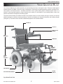
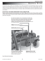
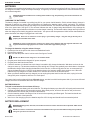
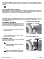
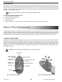
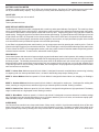
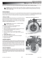
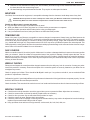
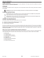
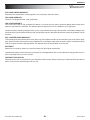
Owners Manual ATTENTION: Please read the content of your owners manual before operating your power chair. Unit 106, Heyford Park Camp Road Upper Heyford, Oxfordshire OX25 5HA ï www.quantumrehab.com SAFETY PRECAUTIONS SAFETY PRECAUTIONS Using your Pride product safely depends upon your diligence in following the warnings, cautions, and instructions in this ownerís manual. Using your Pride product safely also depends upon your own good judgement and/or common sense, as well as that of your provider, caregiver, and/or healthcare professional. Pride is not responsible for injuries and/or damage resulting from any personís failure to follow the warnings, cautions, and instructions in this ownerís manual. Pride is not responsible for injuries and/or damage resulting from any personís failure to exercise good judgement and/or common sense. The symbols below are used throughout this ownerís manual to identify warnings, cautions, and notes. It is very important for you to read and understand them completely. WARNING! Failure to heed the warnings in this owner’s manual may result in personal injury. CAUTION! Failure to heed the cautions in this owner’s manual may result in damage to your power chair. NOTE: Important things to remember when using your power chair. Copyright 2002 Pride Mobility Products Ltd. INFMANU1870/REV D/OCTOBER 2002 Quantum Blast 2 BLAST/REV D/OCTOBER 2002 TABLE OF CONTENTS TABLE OF CONTENTS INTRODUCTION .......................................................................................................................................... 4 INFORMATION EXCHANGE ................................................................................................................. 4 OPERATION .............................................................................................................................................. 5 YOUR QUANTUM BLAST ............................................................................................................................ 7 ELECTRICAL SYSTEM ................................................................................................................................ 9 ELECTRICAL SYSTEM COMPONENTS AND CONNECTORS ......................................................................... 9 BATTERIES .................................................................................................................................. 10 BATTERY REPLACEMENT ................................................................................................................ 10 BATTERIES AND CHARGING-FREQUENTLY ASKED QUESTIONS ................................................................ 11 MOTOR/BRAKE ASSEMBLIES ........................................................................................................... 13 FREEWHEEL LEVER ...................................................................................................................... 13 REMOTE PLUS CONTROLLER .................................................................................................................... 14 JOYSTICK FUNCTIONS ................................................................................................................... 14 WHEELS AND SUSPENSION ....................................................................................................................... 17 DRIVE WHEELS ........................................................................................................................... 17 CASTER WHEELS ......................................................................................................................... 17 ANTI-TIP WHEELS ........................................................................................................................ 17 CARE AND MAINTENANCE ........................................................................................................................ 18 PREVENTIVE MAINTENANCE ............................................................................................................ 18 DAILY CHECKS ............................................................................................................................ 19 WEEKLY CHECKS ......................................................................................................................... 19 MONTHLY CHECKS ....................................................................................................................... 19 YEARLY CHECKS .......................................................................................................................... 20 STORAGE ................................................................................................................................... 20 CLEANING INSTRUCTIONS ............................................................................................................... 20 CORRECTIVE MAINTENANCE ........................................................................................................... 20 WARRANTY ........................................................................................................................................... 21 BLAST/REV D/OCTOBER 2002 3 Quantum Blast INTRODUCTION INTRODUCTION Welcome to Pride Mobility Products Ltd. (Pride). Congratulations on the purchase of your new Quantum Blast. Your Blast design combines the most advanced state-of-the-art components with modern, attractive styling. We are certain that the design features and trouble-free operation of your new power chair will add convenience to your daily living. Please read and follow all instructions in this ownerís manual before attempting to operate your power chair for the first time. If there is anything in this manual you do not understand, or if you require additional assistance for setup, contact your authorised Pride provider. This ownerís manual is compiled from the latest specifications and product information available at the time of publication. We reserve the right to make changes as they become necessary. Any changes to our products may cause slight variations between the illustrations and explanations in this manual and the product you have purchased. If you experience any problems with your power chair that you are unable to resolve, or if you do not feel capable of safely following any of the instructions and/or recommendations contained in this manual, please contact your authorised Pride provider for assistance. Once you understand how to operate and take care of your power chair, we are certain that it will give you years of trouble-free service and enjoyment. INFORMATION EXCHANGE We want to hear your questions, comments, and suggestions regarding this ownerís manual. We would also like to hear about the safety and reliability of your new power chair, and about the service you receive from your authorised Pride provider. Please notify us of any change of address, so we can keep you apprised of important information regarding safety, new products, and new options that can increase your ability to use and enjoy your power chair. Please feel free to write or e-mail us at the address below: Pride Mobility Products Ltd. Unit 106, Heyford Park Camp Road Upper Heyford, Oxfordshire OX25 5HA [email protected] My Authorised Pride Provider Is: Name:_____________________________________________________________________________________________ Address:___________________________________________________________________________________________ Phone Number:_________________ Purchase Date:____________Model:________________Serial #________________ Note: If you ever lose or misplace your warranty card or owner's manual, call or e-mail us and we will be glad to send you a new one immediately. Quantum Blast 4 BLAST/REV D/OCTOBER 2002 OPERATION OPERATION Your power chair is designed to provide optimum stability under normal driving conditions such as dry, level surfaces composed of concrete, blacktop, or asphalt. However, Pride recognises that there may be times when you will encounter other types of surfaces. For this reason, your power chair can also drive on packed soil, grass, and gravel. Feel free to use your power chair safely on dry lawns and in park areas as well. Follow these guidelines: l Reduce your power chair's speed when driving on uneven terrain and/or soft surfaces. l Avoid tall grass that can entangle the running gear. l Avoid loosely packed gravel and sand. l If you feel unsure about a driving surface, avoid that surface. To operate your power chair: 1. Turn on the power. Refer to the ìRemote Plus Controllerî section for more information. 2. Move the joystick in the desired direction. The farther away from the center you move the joystick, the faster the power chair moves. We recommend setting the controller to its slowest setting and practicing simple maneuvers with a trained attendant before going off on your own. HOW TO TRANSFER ONTO AND OFF OF YOUR POWER CHAIR Transferring onto or off your power chair safely requires practice. Always have an attendant or healthcare professional present while learning to properly transfer yourself. WARNING! To eliminate the possibility of injury, Pride recommends that you or a trained attendant perform the following tasks before attempting a transfer: 1. 2. 3. 4. 5. 6. Reduce the distance between your power chair and your transfer destination. Turn the power off. Turn both caster wheels toward the transfer destination to improve power chair stability during transfer. Make sure that your power chair is not in freewheel mode. Make sure the armrests are flipped up or removed from your power chair. Flip the footrest up, or move the leg rests aside; this will help to keep your feet from getting caught on the footrest or on the leg rests during the transfer. MISSING OR DAMAGED PARTS Your power chair is shipped fully assembled. If you think that your power chair is either missing parts or some parts are damaged, please contact your authorised Pride provider immediately. SAFETY PRECAUTIONS WARNING! You should not operate your power chair on public streets and roadways. Be aware that it may be difficult for traffic to see you when you are seated on your power chair. Wait until your path is clear of traffic, and then proceed with extreme caution. Obey all pedestrian traffic rules. WARNING! Never use your power chair to negotiate steps or escalators. You may cause injury to yourself and to others and damage your power chair. WARNING! Avoid icy or slippery conditions and salted surfaces (i.e., walks or roads). WARNING! Consult your physician if you are taking prescribed or over-the-counter medication, or if you have certain physical limitations. Some medications and limitations may impair your ability to operate your power chair in a safe manner. WARNING! Do not operate your power chair while you are under the influence of alcohol, as this may impair your ability to operate your power chair in a safe manner. WARNING! Do not attempt to drive onto an incline without first checking your brakes. If you attempt to drive onto an incline and the brakes are not functioning correctly, you risk serious injury. BLAST/REV D/OCTOBER 2002 5 Quantum Blast OPERATION WARNING! Your power chair's road performance may be influenced by electromagnetic fields caused by mobile telephones or other radiating devices, such as hand-held radios, radio and television stations, wireless computer links, microwave sources, and paging transmitters. WARNING! Your power chair can be a source of electromagnetic and radio frequency interference. MAXIMUM RECOMMENDED GRADE Pride performs extensive testing with on our power chair. Our results indicate that the maximum grade your power chair can climb safely is 8.7% at maximum weight capacity. See figure 1. Seven percent is the angle of most handicap access ramps. Any attempt to climb a steeper grade may put your power chair in an unstable position. Fig. 1. Maximum Recommended Incline Grade Fig. 1a. Maximum Recommended Decline Grade WARNING! Although your power chair may be capable of climbing grades greater than those illustrated above, do not, under any circumstances, exceed the grade guidelines or any other specifications presented in this manual. Doing so could cause instability in your power chair, resulting in personal injury and/or damage to your power chair. WARNING! Always exercise extreme caution when negotiating an incline. Do not zigzag or drive at an angle. Drive your power chair straight up the incline. This greatly reduces the possibility of a tip or a fall. WARNING! You should not travel up or down a potentially hazardous grade (i.e., areas covered with snow, ice, cut grass, or wet leaves). Pride will not be held responsible for injuries and/or property damage resulting from zigzagging, driving at an angle up the face of an grade, failing to exercise extreme caution when negotiating a grade, and/or traveling on a low traction surface grade. WARNING! When on any sort of a grade, never place the power chair in freewheel mode while seated on it or standing next to it. KERB CLIMBING If you are going to attempt to climb onto a kerb, approach it slowly and head-on. Try to keep your power chair moving. If you must stop in the middle of the climb, start again slowly and accelerate cautiously. WARNING! The front anti-tip wheels may cause trouble when ascending or descending a kerb if they are not adjusted correctly. Contact your authorised Pride provider for more information. CORNERS We do not recommend high cornering speeds. While your power chair is equipped with caster wheels and anti-tip wheels for increased stability, excessively high cornering speeds can still create the possibility of tipping. Factors which affect the possibility of tipping include, but are not limited to: l l l l l l cornering speed. steering angle (how sharply you are turning). riding on uneven road surfaces. riding on inclined road surfaces. riding from an area of low traction to an area of high traction (such as passing from a grassy area to a paved area, especially at high speed while turning). making abrupt directional changes. WARNING! To avoid personal injury or property damage, always exercise common sense when cornering. If the situation arises where you have to negotiate a sharp corner, reduce your speed and steering angle (i.e., lessen the sharpness of the turn). This greatly reduces the possibility of a tip or fall. Quantum Blast 6 BLAST/REV D/OCTOBER 2002 YOUR QUANTUM BLAST YOUR QUANTUM BLAST Your Quantum Blast has two main assemblies: the seat and the power base. See figures 2 and 3. There are a wide range of seating options for the Blast, as well as custom configurations. Commonly, the seating assembly contains a seatback, armrests, joystick, and footrest mounts. Your Blast may feature a tilt or recline seating system, alternate joystick mount, or a number of other specialty features to further enhance your mobility. For information on your seating system, refer to the ownerís manual that accompanies the seating system. The power base assembly of the Blast consists of two casters wheels, two drive wheels (see figure 2 and 3), two anti-tip wheels (see figure 3), two drive motors (see figures 7 and 8), two batteries, an electronics controller, and a battery charger (see figure 4). The Remote Plus controller is standard equipment on the Quantum Blast. SEATBACK JOYSTICK REMOTE PLUS KEYPAD SEAT ASSEMBLY ARMRESTS FOOTREST MOUNTS (SWING-AWAY FOOTRESTS) POWER BASE ASSEMBLY DRIVE WHEEL CASTER WHEELS MOTOR/BRAKE ASSEMBLY Fig 2. Blast Front View BLAST/REV D/OCTOBER 2002 7 Quantum Blast YOUR QUANTUM BLAST FREEWHEEL LEVER BATTERY COMPARTMENT DOOR DRIVE WHEEL ANTI-TIP WHEELS Fig 3. Blast Rear View Blast Specifications 35.6 cm (14 in. ) pneumatic, Per-charge 35.6 cm (14 in.) solid (optional) Range 23 cm (9 in.) pneumatic, (solid Electronics optional) 15 cm (6 in. ) solid, suspended, Batter y Charger rear mounted Spor t-Trac rear, All-Conditions Caster Weight Beam front Capacity 14 km/h Base Weight Up to 9.5 cm (3.75 in.) Seat Weight 84 cm (33 in.) Batter y Weight 84.5 cm (33 in.);114.5 cm (45in.) Total Weight w/footrests extension Curb-climbing 68 cm (27 in.) height 136 kg/ 21 Stone (300 lbs.) Drivetrain Two-motor, rear-wheel drive Lifetime limited warranty on frame 2-year limited warranty on electronics 18-month limited warranty on drive motors Batter y Two 12 volt, Group 24 Drive Wheels Front Casters Anti-Tips Suspension Maximum Speed Ground Clearance Turning Radius Overall Length Overall Width Warranty Ground Clearance 9 cm (3½ in.) Optimal up to 25 km (16 km typical use) 100-amp Penny & Giles Remote Plus (standard) Onboard 220-volt (standard) Off-board (optional) 67 kg/ 10.5 Stone (148 lbs.) 14 kg/ 2.2 Stone (31 lbs.) 24 kg/ 4 Stone (53 lbs.) each 129 kg/ 20 Stone (285 lbs.) 9 cm (3.5 in.) 68 cm (27 in.) 87cm (34¼ in.) Moving Forward 99 cm (39 in.) Moving Backward 168 cm (66 in.) Turning Diameter 117cm (46 in.) Quantum Blast 8 BLAST/REV D/OCTOBER 2002 ELECTRICAL SYSTEM ELECTRICAL SYSTEM The electrical system consists of two long-lasting, 12-volt, deep-cycle batteries, the onboard battery charger, the charger ammeter, the self-resetting thermal fuse, and the controller. The batteries sit on the frame, inside the power base. The charger, the ammeter, and the charger fuse are mounted to the frame. Depending on the controller configuration, the controller may be mounted on the end of the armrest, or on the frame. Refer to the controller insert for more specific information on your controller. ELECTRICAL SYSTEM COMPONENTS AND CONNECTORS Electrical system components and connectors are on or inside the Blast power base. The remote controller, the battery charger, and the thermal fuse are located inside the power base. See ìRemote Plus Controllerî for controller information. The ammeter, battery charger AC power receptacle, and the controller harness connector are all located on the front of the Blast power base. See figure 4. SELF-RESETTING THERMAL FUSE (LOCATED INSIDE THE POWER BASE): PROTECTS THE BATTERY CIRCUIT FROM OVERLOADING. WHEN THERE IS AN EXCESSIVE STRAIN ON THE BATTERIES FROM STEEP RECLINES OR HEAVY LOADS, THE THERMAL FUSE WILL REDUCE THE AMOUNT OF CURRENT GOING TO THE CONTROLLER BY 60%. THE CURRENT WILL RETURN TO 100% WHEN THE FUSE COOLS TO WITHIN ITS NORMAL OPERATING TEMPERATURE RANGE. AMMETER: DISPLAYS THE CHARGERíS CURRENT OUTPUT IN AMPS. CHARGER FUSE: PROTECTS THE CHARGING CIRCUIT FROM OVERLOADING. CONTROLLER HARNESS CONNECTOR: THIS IS WHERE THE JOYSTICK/KEYPAD CONNECTS TO THE CONTROLLER. REFER TO ìREMOTE PLUS CONTROLLERî FOR MORE INFORMATION. BATTERY CHARGER AC POWER RECEPTACLE: THIS IS FOR THE BATTERY CHARGER POWER LEAD. Fig. 4. Electrical Connections BLAST/REV D/OCTOBER 2002 9 Quantum Blast ELECTRICAL SYSTEM BATTERIES The batteries are sealed and maintenance free, so there is no need to check the electrolyte fluid level. Deep-cycle batteries are designed to handle a longer and deeper discharge. Though they are similar in appearance to automotive batteries, they are not interchangeable. CAUTION! Automotive batteries are not designed to handle a long, deep discharge, and are also unsafe for use in power chairs. CHARGING THE BATTERIES The battery charger is essential in providing long life for your power chairís batteries. Pride's onboard battery charger is designed to optimise your power chair's performance by charging the batteries safely, quickly, and easily. The charging system consists of the battery charger, the charger fuse, and the ammeter. The ammeter and charger fuse are located on the front of the power base. See figure 4. The ammeter indicates the rate of charge being administered to fully recharge the batteries. It is also a good indication of whether or not the charger is working. The ammeter and the charger are only functional when the charger power lead is plugged into a wall outlet. Your power chair incorporates an inhibit function that disables the power chair when the charger is plugged into a wall outlet. WARNING! Never use an extension cord to plug in your battery charger. Plug the charger directly into a properly wired standard wall outlet. CAUTION! To ensure prolonged life, recharge your power chair's batteries with the supplied onboard or the supplied off-board charging system. Do not use an automotive-type battery charger. To charge the batteries using the onboard charger: 1. Position the front of the power chair close to a standard wall outlet. 2. Power off the controller. 3. Make sure that the power chair is in drive mode. See figures 7 and 8. NOTE: Your Blast will not charge if it is in freewheel mode. 4. Plug the power lead into the chargerís AC power receptacle. 5. Plug the power lead into the wall outlet. 6. Check the ammeter. It indicates how much charge is needed to fully charge the batteries. Wait about a minute for the charger to warm up. The ammeter needle may move as high as 5.5 amps, then gradually move back down to 0 amps as the batteries charge. When charging the batteries for the first time, or after a long period of use, we recommend you charge the batteries for 8 to 14 hours. As the batteries charge, the ammeter needle slowly drops to zero. When the batteries are fully charged, the needle vibrates on or near the zero mark on the ammeter scale. 7. When your Blast's batteries are fully charged, you can unplug the power lead from the wall outlet, unplug it from the charger AC power receptacle, and store it in a safe place. Your power chair may be equipped with an off-board charger, one that is not built into the power chair. If you use an off-board charger, then refer to instructions that came with the charger. BATTERY BREAK-IN To break in new batteries for maximum efficiency: 1. Fully recharge any new battery prior to its initial use. This brings the battery up to about 90% of its peak performance level. 2. Operate your Blast about the house and/or grounds. Move slowly at first, and don't drive too far until you become accustomed to the controls and you break-in the batteries. 3. Give the batteries another full charge of 8 to 14 hours before operating your Blast again. The batteries should now perform at over 90% of their potential. 4. After four or five charging cycles, the batteries top off at 100% charge and should last for an extended period. BATTERY REPLACEMENT WARNING! Battery posts, terminals, and related accessories contain lead and lead compounds. Wash hands after handling. NOTE: It is easier to connect the harnesses to the batteries when you have the batteries away from your Blast. This gives you more room to work. Quantum Blast 10 BLAST/REV D/OCTOBER 2002 ELECTRICAL SYSTEM The batteries on your Blast are located inside the power base, between the drive wheels. Periodically, your batteries will need servicing. You can access the batteries through the access door located at the rear of your Blast. See figures 5 and 6. To access batteries: 1. Slide the door latches inward, toward the center. 2. Pull out the access door, allowing it to fold down like a "tailgate." WARNING! Do not stand on the battery access door. It was not designed to hold passengers or carry cargo. 3. Unplug the battery connectors (there are two connectors located on the right and left sides of the frame in your Blast's battery compartment). 4. Slide the battery tray rearward to the edge of the door. To secure batteries and compartment: 1. Slide the batteries into the compartment until they stop against the front frame stop. 2. Plug the battery terminal connectors into the receptacles on each side of the compartment. 3. Close the door, and slide the latches outward until they latch securely. SLIDE DOOR LATCHES INWARD TO OPEN BATTERY ACCESS DOOR. Fig. 5. Battery Access Door in Up Position Fig. 6. Battery Access Door in Down Position WARNING! Never operate your Blast unless the battery access door is properly secured in the closed position. BATTERIES AND CHARGING-FREQUENTLY ASKED QUESTIONS How does the charger work? The battery charger takes the standard wall outlet voltage of 120 VAC (alternating current) and converts it to 24 VDC (direct current). The Blast batteries use this direct current to run. The lower the battery voltage, the harder the charger must work to recharge the batteries. This is why the ammeter initially may read five or more amps. As the battery voltage approaches full charge, the charger doesn't work as hard to complete the charging cycle. This is why the ammeter drops as it approaches a full charge. When the battery is fully charged, the amperage from the charger is reduced to near zero. This is how the charger maintains a charge but does not overcharge the battery. Your Blast's charger will not operate after the batteries have been discharged to nearly zero voltage. If this happens, call your authorised Pride provider for assistance. BLAST/REV D/OCTOBER 2002 11 Quantum Blast ELECTRICAL SYSTEM Can I use a different battery charger? Use only the charger supplied with the Blast. It is the safest, most efficient tool to charge the batteries. We do not recommend using other types of chargers. How often must I charge the batteries? If you use your Blast on a daily basis, charge the batteries as soon as you are finished using your power chair. Your Blast will be ready each morning to give you a full day's service. If you use your Blast infrequently (once a week or less), you should charge the batteries at least once per week for 12 to 14 hours. NOTE: Keep your batteries fully charged and avoid deeply discharging your batteries. Do not charge the batteries for more than 24 hours at a charging cycle. How can I get maximum range or distance per charge? Rarely do you have an ideal driving situation such as smooth, flat, hard terrain with no wind, hills, or curves. More often you are presented with hills, footpath cracks, uneven and loosely packed surfaces, curves, and wind. All of these factors affect the distance or running time per battery charge. The following are a few suggestions for obtaining the maximum range per charge. l l l l l Always fully charge the batteries prior to your trip. Maintain 30-35 psi in pneumatic drive wheels. Plan your trip in advance to avoid inclines if possible. Limit baggage weight to essential items. Try to maintain an even speed and avoid stop-and-go driving. What type of battery should I use? We recommend deep-cycle batteries that are sealed and maintenance free. Deep-cycle batteries employ a much different chemical technology than that used in car batteries, nickel-cadmium batteries (nicads), or in other common battery types. Deep-cycle batteries are specifically designed to provide power, drain down their charge, and then accept a relatively quick recharge. Sealed lead-acid batteries should be charged as often as possible. They do not have a "memory" like nickelcadmium batteries. Both sealed lead-acid (SLA) and gel cell are deep-cycle batteries that are similar in performance. Use these specifications to reorder deep-cycle batteries: Type: Size: Voltage: Amperage: Deep-cycle (sealed lead-acid or gel cell) Group 24 12 volts each 70 or 80 amp hours Why do my new batteries seem weak? We work closely with our battery manufacturer to provide a battery that best suits your Blast's specific demands. Fresh batteries arrive regularly at Pride and are promptly shipped with a full charge. During shipping, the batteries encounter temperature extremes that may influence initial performance. Heat robs the charge from the battery, and cold slows the power available and extends the time needed to recharge the battery (just as with a car battery). It might take a few days for the temperature of the battery to stabilise and adjust to its new ambient temperature. More importantly, it takes a few "charging cycles" (a partial drain-then a full recharge) to establish the critical chemical balance that is essential to the battery's peak performance and long life. It is well worth it to take the time to break in your battery properly. NOTE: The useful life of a battery is quite often a reflection of the care it receives. How can I ensure maximum battery life? A fully charged, deep-cycle battery provides reliable performance and extended battery life. Keep your Blast's batteries fully charged whenever possible. Batteries that are regularly and deeply discharged, infrequently charged, or stored without a full charge may be permanently damaged, causing unreliable Blast operation and limited battery life. How should I store my Blast and its batteries? If you do not use your Blast regularly, we recommend maintaining battery vitality by charging the batteries at least once a week. If you do not plan on using your Blast for an extended period, fully charge the batteries prior to storage. Disconnect the battery Quantum Blast 12 BLAST/REV D/OCTOBER 2002 ELECTRICAL SYSTEM harnesses and store the Blast in a warm, dry environment. Avoid temperature extremes, such as freezing and excessively hot conditions, and never attempt to charge a frozen battery. A cold or frozen battery should be warmed for several days prior to recharging. NOTE: If you are storing your Blast for an extended period of time, you may wish to block the unit up with several boards under the frame. This keeps the tyres off the ground and prevents the possibility of flat spots developing in the tyres. Are my batteries allowed on public transportation? Sealed lead-acid and gel cell batteries are designed for application in Blasts and in other mobility vehicles. Generally, sealed lead-acid batteries are safe for all forms of transportation such as aircraft, buses, and trains. We suggest that you contact your transportation provider to determine specific requirements of transportation and packaging. What about shipping the batteries? If you wish to use a freight company to ship your Blast to your final destination, repack your Blast in the original shipping container and ship the batteries in separate boxes. How should I dispose of old batteries? If you encounter a damaged or cracked battery, immediately enclose it in a plastic bag and call your authorised Pride provider for instructions on disposal. Your Pride provider will also have the necessary information on battery recycling, which is our recommended course of action. PULL FREEWHEEL LEVER UP TO ENGAGE DRIVE MOTORS. MOTOR/BRAKE ASSEMBLIES Your power chair is equipped with two motor/brake assemblies, one for each drive wheel. Each motor/brake assembly consists of a motor, an electronic brake, and a gearbox. The gearbox features a freewheel lever that disconnects the motor from the gearbox and enables you to move the chair manually. To check the brakes: 1. Turn on the controller and set it to the slowest speed setting. See ìRemote Plus Controller.î 2. After one second, check the battery condition meter. Make sure that it remains on. 3. Slowly push the joystick forward until you hear the electric brakes click. Immediately release the joystick. You must be able to hear each electrical brake operating within a few seconds of joystick movement. Repeat this test three times, pushing the joystick rearward, then left, and then right. Fig. 7. Drive Motors Engaged (Drive Mode) PULL OUT AND ROTATE FREEWHEEL LEVER DOWN TO DISENGAGE DRIVE MOTORS. MOTOR BRUSH CAPS FREEWHEEL LEVER This lever allows you to disengage the drive motors and maneuver your Blast manually. See figures 7 and 8. WARNING! Do not use your Blast while the drive motors are disengaged unless you are in the presence of an attendant. Do not disengage the drive motors when your Blast is on an incline. The chair could roll down on its own, causing injury! CAUTION! It is important to remember that when your Blast is in freewheel mode, the braking system is disengaged. NOTE: If the lever is difficult to move in either direction, rock your Blast back and forth slightly while moving the lever. BLAST/REV D/OCTOBER 2002 13 Fig. 8. Drive Motors Disengaged (Freewheel Mode) Quantum Blast ELECTRICAL SYSTEM MOTOR BRUSHES The electric motors that power your Blast use carbon brushes. These brushes may become susceptible to wear over a long period of time. The motor brushes are the two contacts located inside the motor assembly that supply power to the motor. They are designed to provide several thousand hours of operation. However, if the brushes become dirty with carbon deposits or wear out, the motor will run poorly or not at all. If inspection determines excessive wear on the brushes, they must be replaced or motor damage will result. NOTE: Failure to maintain the brushes could void your Blast's warranty. To inspect or replace the motor brushes: 1. Remove the seat and batteries. 2. Unscrew the motor brush caps. 3. Remove the brushes. 4. Inspect for wear. 5. Replace brushes, if necessary. Contact your authorised Pride provider for replacement brushes. REMOTE PLUS CONTROLLER The standard electronics is the Remote Plus controller system. The Remote Plus controller system consists of the keypad and the controller box. The keypad sends signals to the controller box through a cable that is attached to the back of the joystick and to the controller, through a connector on the power base. The Remote Plus keypad is typically located at the end of either the right or the left armrest. The Remote Plus controller box is located underneath the front of the power base. JOYSTICK FUNCTIONS The joystick controls the direction and speed of the power chair. See figure 9 and 10. When you move the joystick from the neutral (center) position, the electromagnetic brakes release and allow the power chair to move. The further you push the joystick from its neutral position, the faster your Blast moves. When you release the joystick and allow it to return to the neutral position, you engage the electromagnetic brakes. This causes the chair to decelerate and come to a complete stop. If your Blast begins to move in an unexpected manner, immediately release the joystick. Unless the joystick is damaged, this action should stop your Blast. WARNING! Use the on/off key to stop your chair in an emergency only. ON/OFF KEY HAZARD WARNING KEY TURN INDICATOR SPEED INDICATOR MODE KEY LIGHT KEY BATTERY CONDITION METER TURN INDICATOR HORN KEY JOYSTICK Fig. 10. Joystick Movement Fig. 9. Remote Plus Keypad Quantum Blast 14 BLAST/REV D/OCTOBER 2002 REMOTE PLUS CONTROLLER BATTERY CONDITION METER The battery condition meter consists of 10 LEDs over the speed indicator. See figure 9. These lights are an accurate indication of your usable battery capacity. They also alert you of any faults found within your unit. See ìTrouble Codes.î ON/OFF KEY The on/off key turns your unit on and off. HORN KEY This key activates the horn. MODE KEY AND SPEED INDICATOR The Remote Plus joystick controller is equipped with a mode key and a speed indicator. See figure 9. The mode key allows you to access different power chair functions. Activating the mode key allows you to adjust the maximum power chair speed. To increase or decrease the overall speed, activate the mode key once. Pushing the joystick to the right will increase the speed setting. Pushing the joystick to the left will decrease the speed setting. The speed indicator LEDs will light up from left to right. When one LED is lit, the speed is in the slowest setting. When all five LEDs are lit, the speed is in the fastest setting. After selecting your desired speed, activate the mode key again to return to drive, or simply activate the joystick in the forward or reverse direction and your Blast will operate at the selected speed setting. If your Blast is equipped with power seat functions, you can access seat control by pressing the mode key twice. Push the joystick to the right to toggle to your desired seat function. The LED will light in various positions indicating which seat function is active. When the LED is lit in the appropriate section, push the joystick forward to raise the actuator and pull the joystick in reverse to lower the actuator. To return to drive, activate the mode key again. DRIVE MODES Conventional power chair electronics feature a single program that dictates how the chair operates, with settings in acceleration, deceleration, turn rate, and so on. The drawback of the single program system is that, fast or slow, the chair is still using the same program. The handling characteristics of a power chair are far different at 2 mph versus 8 mph, so it goes against best performance under a wide range of uses to have only one program (it's like driving your car in one gear, whether you're in stop-and-go traffic or on the freeway). With the Blast, we've configured 5 unique programs to optimise performance within each environment use as follows: MODE 1 - Indoor Slow: Maximum speed is 3 km/h. Mode 1 is designed for smooth, controlled indoor maneuvering, including on carpeting and over doorway thresholds. Also, it is ideal for descending steep ramps. Braking is fast. MODE 2 - Indoor Medium: Maximum speed is 5.5 km/h. Mode 2 is designed for faster indoor use, shopping, etc. Braking is fast. MODE 3 - Outdoor Medium: Maximum speed is 9 km/h. Mode 3 is designed for outdoor use. Good speed for walking with others, traveling on rough surfaces, and where high torque at slower speeds is needed. Braking is medium. MODE 4 - Outdoor Fast: Maximum speed is 13.6 km/h. Mode 4 is designed for long-distance, high-speed travel. The battery range is maximised, as is high-speed control. Braking is medium. MODE 5 - Blast Mode: Maximum speed is 13.6 km/h mph. Mode 5 is designed to overcome obstacles in outdoor settings only. Ultra high torque and acceleration allows user to surmount obstacles, pull out of holes, and accelerate rapidly uphill. Reduced battery range if used frequently. Braking is medium. SLEEP MODE Your Remote Plus controller has a sleep mode feature. Sleep mode is a built-in circuit that automatically shuts off the main power if the joystick is not moved in any direction for approximately five minutes. The battery condition meter lights on the joystick indicate sleep mode by blinking once every five seconds. To restore power and continue, push the on/off key twice. BLAST/REV D/OCTOBER 2002 15 Quantum Blast REMOTE PLUS CONTROLLER CONTROLLER FOLDBACK The Remote Plus controller is equipped with a thermal rollback circuit. This circuit monitors the temperature of the motors and the controller. In the event that the motors or the controller become excessively hot (above 50C/122F), the controller reduces the motor voltage. For every degree above 50C/122F, the controller reduces the voltage by 5 volts. This reduces your Blastís speed and allows the electrical components to cool down. When the temperature returns to a safe level, your Blast resumes its normal speed. TROUBLE CODES In addition to indicating the current state of battery charge, the battery condition meter can also indicate possible problems with your Blast. The battery condition meter has ten individual bars. The bars provide information by the number of bars that are flashing. If the meter is flashing rapidly, the controller may be indicating a fault. For instance, the very first red bar flashing rapidly indicates the battery voltage is nearly depleted. The following is a list of the possible errors signified by the rapidly flashing meter lights. Flashing Bars Diagnosis Solution 10 Green 9 Green 8 Green 7 Yellow 6 Yellow 5 Yellow 4 Yellow 3 Red 2 Red 1 Red High Battery Voltage Solenoid Brake Fault Possible Controller Fault Possible Joystick Fault Inhibit Active Right Motor Wiring Fault Right Motor Disconnected Left Motor Wiring Fault Left Motor Disconnected Low Battery Voltage Check Batteries Check Motor/Brake Wiring See Authorised Pride Provider See Authorised Pride Provider Unplug Charger/Check Connections Check Right Motor Wiring Check Right Motor Wiring Check Left Motor Wiring Check Left Motor Wiring Check Batteries/Battery Wiring If you cannot resolve your problem, see your authorised Pride provider. REMOTE PLUS OPTIONAL FEATURES See figure 9 to reference the following optional features: l l l Light Key: If your Blast is equipped with the deluxe lighting package, the light key activates the lights. Turn Indicator Keys: The arrow keys activate the turn indicators regardless of whether or not your Blast is powered off or on. Hazard Warning Key: This key operates the hazard lights. Quantum Blast 16 BLAST/REV D/OCTOBER 2002 WHEELS AND SUSPENSION WHEELS AND SUSPENSION Your Blast is equipped with three sets of wheel assemblies: two anti-tip wheels, two drive wheels, and two caster wheels. Each of the wheels has its own suspension system that increases your comfort, traction, stability, and safety. WARNING! The drive wheel and caster suspension system are optimised at the factory and should not be adjusted by the user. If you alter either system, you may affect the Blast’s handling characteristics. This may result in serious injury. DRIVE WHEELS Your Quantum Blast uses two 36 cm (14 in.) drive wheels that are directly connected to the motor/gearbox assembly. The drive wheels have either solid inserts or pneumatic tubes. The drive wheels feature a rear Sport-Trac Suspension (STS) which provides comfort and increased performance by independently suspending the rear drive wheels. TYRES AND TUBES If your Blast is equipped with pneumatic tyres, you should check the air pressure at least once a week. This prolongs the life of your tyres and helps ensure smooth operation of your chair. If you have a flat tyre, replace the tube. Replacement tyres and tubes are readily available through your authorised Pride provider. REMOVE HUB TO EXPOSE DRIVE WHEEL NUT. WARNING! Make sure the tyre is completely deflated before attempting repair. Follow these easy steps for a quick and safe repair: 1. Completely deflate the tyre if pneumatic. 2. Remove the hubcap. 3. Use a 1.9 cm (3/4 in.) socket spanner to remove the drive wheel nut from the center hub of the wheel. See figure 11. 4. Pull the wheel off of the axle. 5. Remove the bolts that hold the wheel halves together. 6. Remove the old tube and/or tyre and replace it with a new tube and/or tyre. 7. Reassemble the wheel. 8. Slide the wheel back onto the shaft. 9. Install the drive wheel bolt into the center hub and tighten. 10. Inflate the tyre to 30-35 psi. 11. Replace the hubcap. Fig. 11. Drive Wheel CASTER WHEELS The caster wheels are located on the front of your Blast and are part of the All-Conditions Caster Beam (ACC) suspension system. See figure 12. The ACC works by suspending the front casters on a pivoting beam, allowing the caster wheels to conform to uneven terrain. ACC, combined with STS, allows the front and rear wheels of your Blast to articulate independently, dramatically increasing stability and traction when traversing off-road and uneven terrain. ANTI-TIP WHEELS Your Blast is equipped with spring-loaded rear anti-tip wheels, which travel up and down to prevent them from catching on obstacles. Additionally, the anti-tip wheels are linked to the drive wheels and actively react to sudden rearward weight shifts, enhancing stability and safety. See figure 13. Fig. 12. Caster Wheel BLAST/REV D/OCTOBER 2002 17 Quantum Blast WHEELS AND SUSPENSION According to personal needs and lifestyle, you may wish to adjust the height of the anti-tips. By raising the anti-tip wheels, ground clearance increases, as does your Blast's ability to "wheelie" for obstacle climbing. Lowering the anti-tip wheels decreases the ground clearance, as well as limits rearward pitching, increasing stability. To adjust anti-tip wheels: 1. Remove the anti-tip axle bolt and nylon spacers using two, 1.27 cm ( in.) spanners. See figure 13. 2. Relocate the anti-tip wheel to one of the four adjustment holes, as desired. 3. Replace the wheel, placing the nylon washers on each side of the wheel, then replacing the axle bolt through the center. 4. Tighten the axle bolt and nut so that the wheel spins freely but does not wobble side-to-side. 5. Repeat the process on the other anti-tip. ANTI-TIP WHEELS ANTI-TIP AXLE BOLT ADJUSTMENT HOLE Fig. 13. Anti-tip Wheels CARE AND MAINTENANCE PREVENTIVE MAINTENANCE Like any motorised vehicle, your Blast requires simple preventive maintenance that can extend its service life. You can perform some of these checks. But other checks require assistance from an authorised Pride provider. Preventive maintenance is very important. If you follow the preventive maintenance guidelines in this section as scheduled, you can help ensure that your Blast gives you years of trouble-free operation. If you have any doubt as to your Blast's care or operation, contact your authorised Pride provider. GENERAL GUIDELINES l Avoid knocking or bumping the controller, especially the joystick. l Keep the controller clean. l Check all controller connectors on the utility tray to ensure that they are all tight and secured properly. l When the battery condition meter is completely lit, the batteries are fully charged and the controller and the electrical system are OK. l If one red bar on the battery condition meter is blinking slowly, the batteries are low and need to be charged, but the controller and the electrical system are OK. l If the battery condition meter is blinking rapidly, the controller has detected a fault in either its own circuits or in your Blast's circuits. Refer to ìTrouble Codesî for more information. l Make sure the drive tyres are inflated to 30-35 psi. WARNING! Overinflating tyres can cause them to explode and can result in personal injury. WARNING! Do not use a high pressure hose to inflate your tyres. l Use a rubber conditioner on the tyre sidewalls to help preserve them. WARNING! Never use a rubber conditioner on the tread area of the tyres; doing so may make the tyres slippery and may cause your Blast to skid. l l The body shroud has been sprayed with a clear sealant coating. You can apply a light coat of car wax to the shroud to help it retain its high-gloss appearance. Check all electrical connections. Make sure they are tight and are not corroded. Quantum Blast 18 BLAST/REV D/OCTOBER 2002 CARE AND MAINTENANCE l l Batteries must sit flat within the battery well, with the battery terminals facing inward, toward each other. Refer to the frame decal for the correct wiring layout. All wheel bearings are prelubricated and sealed. They require no subsequent lubrication. MOISTURE Your Blast, like most electrical equipment, is susceptible to damage from the elements. Avoid damp areas of any kind. CAUTION! Direct exposure to water or dampness could cause your Blast to malfunction electronically and mechanically. Water can cause electrical components to corrode and the chair's frame to rust. Should your Blast come in contact with water: l Dry your Blast as thoroughly as possible with a dry towel. l Allow your Blast to sit in a warm, dry place for 12 hours to allow unseen water to evaporate. l Check the joystick operation and the brakes before using your Blast again. l If any inconsistencies are found, take your Blast to an authorised Pride provider. TEMPERATURE Some of the parts of your Blast are susceptible to extreme changes in temperature. Always keep your Blast between the temperatures of -8C/18F and 50C/122F. In extremely cold temperatures the batteries may freeze. The specific temperature at which they freeze depends on a number of factors, such as battery charge, usage, and composition of the batteries (e.g., sealed lead-acid or gel cell). Temperatures above 50C/122F may cause your Blast to operate at a reduced speed. This reduced speed is a safety feature built into the controller that helps prevent damage to the motor and other electrical components. Refer to ìController Foldbackî for more information. DAILY CHECKS With the controller turned off, check the joystick. Make sure it is not bent or damaged and that it returns to the center position when you release it. Check the rubber boot around the base of the joystick for damage. Visually inspect the boot. Do not handle or try to repair it. See your authorised Pride provider if there is a problem. Visually inspect the controller harnesses. Make sure that they are not frayed or cut or have any wires exposed. See your authorised Pride provider if there is a problem with any of these harnesses. WEEKLY CHECKS Disconnect and inspect the controller and the charger harnesses from the utility tray. Look for corrosion. Contact your authorised Pride provider if necessary. Ensure that all parts of the controller system are securely fastened to your Blast. Do not overtighten any screws. Check for proper tyre inflation. There should be 30-35 psi in each tyre. If a tyre does not hold air, see an authorised Pride provider for replacement of the tube. Calibrate the joystick if a noticeable difference in performance is detected or if the joystick does not operate properly. You can do this for the Remote Plus and Europa controllers. Check the brakes. This test should be carried out on a level surface with at least three feet of clearance around your Blast. MONTHLY CHECKS l l l l l l Check that the anti-tip wheels do not rub the ground when you are operate the Blast. Adjust them as necessary. Check for extreme wear on the anti-tip wheels. Replace them as necessary. Check for drive tyre wear. See an authorised Pride provider for repair. Check the casters for wear. Replace them as necessary. Check the caster forks for damage or fluttering which indicates that they may need to be adjusted or have the bearings replaced. See an authorised Pride provider for repair. Keep your Blast clean and free of foreign material, such as mud, dirt, hair, food, drink, etc. BLAST/REV D/OCTOBER 2002 19 Quantum Blast CARE AND MAINTENANCE YEARLY CHECKS Take your Blast to an authorised Pride provider for yearly maintenance. This helps ensure that your Blast is functioning properly and helps prevent future complications. STORAGE Your power chair should be stored in a dry place, free from temperature extremes. When storing, disconnect the batteries from the Blast. WARNING! If you fail to store the unit properly, the frame can rust and the electronics can be damaged. CLEANING INSTRUCTIONS CAUTION! Never hose off your Blast or place it in direct contact with water. Your Blast has a painted plastic body shroud that allows it to be easily wiped clean with a damp cloth. CAUTION! Never use any chemicals to clean a vinyl seat, as they may cause the seat to become slippery or dry out and crack. Use soapy water and dry the seat thoroughly. CORRECTIVE MAINTENANCE If the battery condition meter does not light up when you turn on the power: l l l Check the harness connections. Make sure they are tight. Check the circuit breaker. Reset it if necessary. Check the battery connections. If the above conditions prove normal, you can load test the batteries with a battery load tester. These testers are available at automotive parts stores. Disconnect both batteries before load testing and follow the directions that come with the load tester. If either one of the batteries fails the load test, replace both of them. If your Blast still does not power up, contact your authorised Pride provider. WHEN TO SEE YOUR AUTHORIZED PRIDE PROVIDER FOR SERVICE The following symptoms could indicate a serious problem with your Blast. If necessary, contact your authorised Pride provider. When calling, have the model number, serial number, nature of the problem, and the trouble code if available. l l l l l l l l l Motor noise Frayed harnesses Cracked or broken connectors Uneven wear on any of the tyres Jerky motion Pulling to one side Bent or broken wheel assemblies Does not power up Powers up, but does not move Quantum Blast 20 BLAST/REV D/OCTOBER 2002 WARRANTY WARRANTY FIVE-YEAR LIMITED WARRANTY Structural frame components, including platform, fork, seat posts, and frame welds. TWO-YEAR WARRANTY Drivetrain, including differential, motor, and brakes. ONE-YEAR WARRANTY Your Pride Power Chair is fully guaranteed for twelve (12) months from the date of purchase against faults arising due to defects in manufacture or materials. This warranty does not detract from, but is in addition to your legal rights. All electronic parts, including controllers, have a one (1) year warranty. Servicing to the controller or the battery chargers must be carried out by your authorised Pride provider. Any attempt to open or dismantle these items renders the guarantee void on that item. NOT COVERED UNDER WARRANTY This warranty does not extend to those items which may need replacement due to wear and tear (tyres, belts, bulbs, upholstery, plastic shrouds, motor brushes, fuses, and batteries), or damage to the product caused by misuse or accident for which Pride or its agent cannot be held responsible. This warranty does not include labor or service calls. BATTERIES Batteries are covered by a twelve (12) month warranty from the original manufacturer. Gradual deterioration in performance due to being left in a discharged state, left in cold conditions for long periods of time, or worn out through heavy use is not covered. WARRANTY EXCLUSIONS Warranty service can be performed by your authorised Pride provider. Please contact your authorised Pride provider for advice on the current cost affecting the service visit. BLAST/REV D/OCTOBER 2002 21 Quantum Blast NOTES NOTES Quantum Blast 22 BLAST/REV D/OCTOBER 2002 NOTES NOTES BLAST/REV D/OCTOBER 2002 23 Quantum Blast Quality Control - Quantum Blast 850 Model #______________ Serial #______________ Controller Serial # Fit and Finish Inclusion of all Parts Performance Pride keeps a more detailed report on file at the factory. Date Inspected Inspector Thank you for making the Quantum Blast Series your choice in power chairs. We have thoroughly inspected your Quantum Blast. The following check marks indicate that it has been tested, driven, and inspected. # In Q 1 uali ty