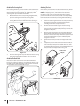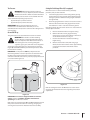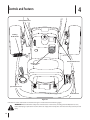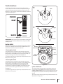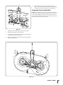
1
Safe Operation Practices • Set-Up • Operation • Maintenance • Service • Troubleshooting • Warranty
Operator’s Manual
Hydrostatic Lawn Tractor — Model Series 790
WARNING
READ AND FOLLOW ALL SAFETY RULES AND INSTRUCTIONS IN THIS MANUAL
BEFORE ATTEMPTING TO OPERATE THIS MACHINE.
FAILURE TO COMPLY WITH THESE INSTRUCTIONS MAY RESULT IN PERSONAL INJURY.
MTD LLC, P.O. BOX 361131 CLEVELAND, OHIO 44136-0019
Printed In USA
Form No. 769-06300
(January 1, 2011)
1
To The Owner
Thank You
Thank you for purchasing a lawn tractor manufactured by
MTD LLC. It was carefully engineered to provide excellent
performance when properly operated and maintained.
Please read this entire manual prior to operating the equipment.
It instructs you how to safely and easily set up, operate and
maintain your machine. Please be sure that you, and any other
persons who will operate the machine, carefully follow the
recommended safety practices at all times. Failure to do so could
result in personal injury or property damage.
All information in this manual is relative to the most recent
product information available at the time of printing. Review
this manual frequently to familiarize yourself with the machine,
its features and operation. Please be aware that this Operator’s
Manual may cover a range of product specifications for various
models. Characteristics and features discussed and/or illustrated
in this manual may not be applicable to all models. MTD LLC
reserves the right to change product specifications, designs and
equipment without notice and without incurring obligation.
If you have any problems or questions concerning the machine,
phone your local authorized MTD service dealer or contact us
directly. MTD’s Customer Support telephone numbers, website
address and mailing address can be found on this page. We want
to ensure your complete satisfaction at all times.
Throughout this manual, all references to right and left side of the
machine are observed from the operating position
The engine manufacturer is responsible for all engine-related
issues with regards to performance, power-rating, specifications,
warranty and service. Please refer to the engine manufacturer’s
Owner’s/Operator’s Manual, packed separately with your
machine, for more information.
Table of Contents
Safe Operation Practices......................................... 3 Troubleshooting..................................................... 28
Assembly & Set-Up................................................... 9 Replacement Parts................................................. 29
Controls & Features.................................................12 Attachments & Accessories................................... 30
Operation.................................................................15 CA. Emission Control Statement........................... 34
Maintenance & Adjustment..................................19 Warranty................................................................. 36
Service..................................................................... 24
Record Product Information
Before setting up and operating your new equipment, please
locate the model plate on the equipment and record the
information in the provided area to the right. You can locate the
model plate by looking beneath the seat. This information will
be necessary, should you seek technical support via our web site,
Customer Support Department, or with a local authorized service
dealer.
Model Number
Serial Number
Customer Support
Please do NOT return the machine to the retailer or dealer without first contacting our Customer Support Department.
If you have difficulty assembling this product or have any questions regarding the controls, operation, or maintenance of
this machine, you can seek help from the experts. Choose from the options below:
2
◊
Visit us on the web at www.mtdproducts.com
◊
Call a Customer Support Representative at (800) 800-7310 or (330) 220-4683
◊
Write us at MTD LLC • P.O. Box 361131 • Cleveland, OH • 44136-0019
Important Safe Operation Practices
2
WARNING! This symbol points out important safety instructions which, if not followed,
could endanger the personal safety and/or property of yourself and others. Read and follow
all instructions in this manual before attempting to operate this machine. Failure to comply
with these instructions may result in personal injury.
When you see this symbol. HEED ITS WARNING!
California Proposition 65
WARNING! Engine Exhaust, some of its constituents, and certain vehicle components
contain or emit chemicals known to State of California to cause cancer and birth defects
or other reproductive harm.
WARNING! Battery posts, terminals, and related accessories contain lead and lead
compounds, chemicals known to the State of California to cause cancer and reproductive
harm. Wash hands after handling
DANGER! This machine was built to be operated according to the safe operation practices in
this manual. As with any type of power equipment, carelessness or error on the part of the
operator can result in serious injury. This machine is capable of amputating hands and feet
and throwing objects. Failure to observe the following safety instructions could result in
serious injury or death.
General Operation
1.
Read, understand, and follow all instructions on the
machine and in the manual(s) before attempting to
assemble and operate. Keep this manual in a safe place for
future and regular reference and for ordering replacement
parts.
2.
Be familiar with all controls and their proper operation.
Know how to stop the machine and disengage them
quickly.
3.
Never allow children under 14 years of age to operate this
machine. Children 14 and over should read and understand
the instructions and safe operation practices in this manual
and on the machine and should be trained and supervised
by an adult.
4.
Never allow adults to operate this machine without proper
instruction.
5.
To help avoid blade contact or a thrown object injury,
keep bystanders, helpers, children and pets at least 75 feet
from the machine while it is in operation. Stop machine if
anyone enters the area.
6.
Thoroughly inspect the area where the equipment is to be
used. Remove all stones, sticks, wire, bones, toys, and other
foreign objects which could be picked up and thrown by
the blade(s). Thrown objects can cause serious personal
injury.
7.
Plan your mowing pattern to avoid discharge of material
toward roads, sidewalks, bystanders and the like. Also,
avoid discharging material against a wall or obstruction
which may cause discharged material to ricochet back
toward the operator.
8.
Always wear safety glasses or safety goggles during
operation and while performing an adjustment or repair
to protect your eyes. Thrown objects which ricochet can
cause serious injury to the eyes.
9.
Wear sturdy, rough-soled work shoes and close-fitting
slacks and shirts. Loose fitting clothes and jewelry can be
caught in movable parts. Never operate this machine in
bare feet or sandals.
10.
Be aware of the mower and attachment discharge direction
and do not point it at anyone. Do not operate the mower
without the discharge cover or entire grass catcher in its
proper place.
11.
Do not put hands or feet near rotating parts or under the
cutting deck. Contact with the blade(s) can amputate
hands and feet.
3
12.
A missing or damaged discharge cover can cause blade
contact or thrown object injuries.
13.
Stop the blade(s) when crossing gravel drives, walks, or
roads and while not cutting grass.
14.
Watch for traffic when operating near or crossing
roadways. This machine is not intended for use on any
public roadway.
15.
Do not operate the machine while under the influence of
alcohol or drugs.
16.
Mow only in daylight or good artificial light.
17.
Never carry passengers.
18.
Disengage blade(s) before shifting into reverse. Back up
slowly. Always look down and behind before and while
backing to avoid a back-over accident.
19.
Slow down before turning. Operate the machine smoothly.
Avoid erratic operation and excessive speed.
20.
Disengage blade(s), set parking brake, stop engine and wait
until the blade(s) come to a complete stop before removing
grass catcher, emptying grass, unclogging chute, removing
any grass or debris, or making any adjustments.
21.
Never leave a running machine unattended. Always turn
off blade(s), place transmission in neutral, set parking
brake, stop engine and remove key before dismounting.
22. Use extra care when loading or unloading the machine into
a trailer or truck. This machine should not be driven up or
down ramp(s), because the machine could tip over, causing
serious personal injury. The machine must be pushed
manually on ramp(s) to load or unload properly.
23.
Muffler and engine become hot and can cause a burn. Do
not touch.
24.
Check overhead clearances carefully before driving under
low hanging tree branches, wires, door openings etc.,
where the operator may be struck or pulled from the
machine, which could result in serious injury.
25.
Disengage all attachment clutches, depress the brake
pedal completely and shift into neutral before attempting
to start engine.
26.
27.
Your machine is designed to cut normal residential grass of
a height no more than 10”. Do not attempt to mow through
unusually tall, dry grass (e.g., pasture) or piles of dry leaves.
Dry grass or leaves may contact the engine exhaust and/
or build up on the mower deck presenting a potential fire
hazard.
Use only accessories and attachments approved for this
machine by the machine manufacturer. Read, understand
and follow all instructions provided with the approved
accessory or attachment.
28. Data indicates that operators, age 60 years and above, are
involved in a large percentage of riding mower-related
injuries. These operators should evaluate their ability
to operate the riding mower safely enough to protect
themselves and others from serious injury.
29.
4
If situations occur which are not covered in this manual, use
care and good judgment. Contact your customer service
representative for assistance.
Section 2 — Important Safe Operation Practices
Slope Operation
Slopes are a major factor related to loss of control and tip-over
accidents which can result in severe injury or death. All slopes
require extra caution. If you cannot back up the slope or if you
feel uneasy on it, do not mow it.
For your safety, use the slope gauge included as part of this
manual to measure slopes before operating this machine on
a sloped or hilly area. If the slope is greater than 15 degrees as
shown on the slope gauge, do not operate this machine on that
area or serious injury could result.
Do:
1.
Mow up and down slopes, not across. Exercise extreme
caution when changing direction on slopes.
2.
Watch for holes, ruts, bumps, rocks, or other hidden
objects. Uneven terrain could overturn the machine. Tall
grass can hide obstacles.
3.
Use slow speed. Choose a low enough speed setting so
that you will not have to stop or shift while on the slope.
Tires may lose traction on slopes even though the brakes
are functioning properly. Always keep machine in gear
when going down slopes to take advantage of engine
braking action.
4.
Follow the manufacturer’s recommendations for wheel
weights or counterweights to improve stability.
5.
Use extra care with grass catchers or other attachments.
These can change the stability of the machine.
6.
Keep all movement on the slopes slow and gradual. Do
not make sudden changes in speed or direction. Rapid
engagement or braking could cause the front of the
machine to lift and rapidly flip over backwards which could
cause serious injury.
7.
Avoid starting or stopping on a slope. If tires lose traction,
disengage the blade(s) and proceed slowly straight down
the slope.
Do Not:
1.
Do not turn on slopes unless necessary; then, turn slowly
and gradually downhill, if possible.
2.
Do not mow near drop-offs, ditches or embankments. The
mower could suddenly turn over if a wheel is over the edge
of a cliff, ditch, or if an edge caves in.
3.
Do not try to stabilize the machine by putting your foot on
the ground.
4.
Do not use a grass catcher on steep slopes.
5.
Do not mow on wet grass. Reduced traction could cause
sliding.
6.
Do not shift to neutral and coast downhill. Over-speeding
may cause the operator to lose control of the machine
resulting in serious injury or death.
7.
Do not tow heavy pull behind attachments (e.g. loaded
dump cart, lawn roller, etc.) on slopes greater than 5
degrees. When going down hill, the extra weight tends
to push the tractor and may cause you to loose control
(e.g. tractor may speed up, braking and steering ability are
reduced, attachment may jack-knife and cause tractor to
overturn).
Children
Service
1.
Safe Handling of Gasoline:
Tragic accidents can occur if the operator is not alert to the
presence of children. Children are often attracted to the
machine and the mowing activity. They do not understand
the dangers. Never assume that children will remain where
you last saw them.
a.
Keep children out of the mowing area and in
watchful care of a responsible adult other than the
operator.
b.
Be alert and turn machine off if a child enters the
area.
c.
Before and while backing, look behind and down for
small children.
d.
Never carry children, even with the blade(s) shut off.
They may fall off and be seriously injured or interfere
with safe machine operation.
e.
Use extreme care when approaching blind corners,
doorways, shrubs, trees or other objects that may
block your vision of a child who may run into the
path of the machine.
f.
2.
1.
To avoid back-over accidents, always disengage
the cutting blade(s) before shifting into Reverse.
If equipped, the “Reverse Caution Mode” should
not be used when children or others are around.
g.
Keep children away from hot or running engines.
They can suffer burns from a hot muffler.
h.
Remove key when machine is unattended to prevent unauthorized operation.
Never allow children under 14 years of age to operate this
machine. Children 14 and over should read and understand
the instructions and safe operation practices in this manual
and on the machine and should be trained and supervised
by an adult.
To avoid personal injury or property damage use extreme
care in handling gasoline. Gasoline is extremely
flammable and the vapors are explosive. Serious
personal injury can occur when gasoline is spilled on
yourself or your clothes which can ignite. Wash your skin
and change clothes immediately.
a.
Use only an approved gasoline container.
b.
Never fill containers inside a vehicle or on a truck
or trailer bed with a plastic liner. Always place
containers on the ground away from your vehicle
before filling.
c.
When practical, remove gas-powered equipment
from the truck or trailer and refuel it on the ground.
If this is not possible, then refuel such equipment on
a trailer with a portable container, rather than from a
gasoline dispenser nozzle.
d.
Keep the nozzle in contact with the rim of the fuel
tank or container opening at all times until fueling is
complete. Do not use a nozzle lock-open device.
e.
Extinguish all cigarettes, cigars, pipes and other
sources of ignition.
f.
Never fuel machine indoors.
g.
Never remove gas cap or add fuel while the engine
is hot or running. Allow engine to cool at least two
minutes before refueling.
h.
Never over fill fuel tank. Fill tank to no more than ½
inch below bottom of filler neck to allow space for
fuel expansion.
i.
Replace gasoline cap and tighten securely.
j.
If gasoline is spilled, wipe it off the engine and
equipment. Move machine to another area. Wait 5
minutes before starting the engine.
Towing
1.
Tow only with a machine that has a hitch designed for
towing. Do not attach towed equipment except at the
hitch point.
k.
2.
Follow the manufacturers recommendation for weight
limits for towed equipment and towing on slopes.
To reduce fire hazards, keep machine free of grass,
leaves, or other debris build-up. Clean up oil or fuel
spillage and remove any fuel soaked debris.
l.
3.
Never allow children or others in or on towed equipment.
4.
On slopes, the weight of the towed equipment may cause
loss of traction and loss of control.
Never store the machine or fuel container inside
where there is an open flame, spark or pilot light
as on a water heater, space heater, furnace, clothes
dryer or other gas appliances.
5.
Always use extra caution when towing with a machine
capable of making tight turns (e.g. “zero-turn” ride-on
mower). Make wide turns to avoid jack-knifing.
General Service
6.
Travel slowly and allow extra distance to stop.
1.
7.
Do not shift to neutral and coast downhill.
Never run an engine indoors or in a poorly ventilated area.
Engine exhaust contains carbon monoxide, an odorless,
and deadly gas.
2.
Before cleaning, repairing, or inspecting, make certain the
blade(s) and all moving parts have stopped. Disconnect the
spark plug wire and ground against the engine to prevent
unintended starting.
m. Allow a machine to cool at least five minutes before
storing.
Section 2 — Important Safe Operation Practices
5
Periodically check to make sure the blades come to
complete stop within approximately (5) five seconds after
operating the blade disengagement control. If the blades
do not stop within the this time frame, your machine
should be serviced professionally by an authorized MTD
Service Dealer.
Do not modify engine
4.
Check brake operation frequently as it is subjected to wear
during normal operation. Adjust and service as required.
Notice Regarding Emissions
5.
Check the blade(s) and engine mounting bolts at frequent
intervals for proper tightness. Also, visually inspect blade(s)
for damage (e.g., excessive wear, bent, cracked). Replace
the blade(s) with the original equipment manufacturer’s
(O.E.M.) blade(s) only, listed in this manual. “Use of parts
which do not meet the original equipment specifications
may lead to improper performance and compromise
safety!”
3.
6.
Mower blades are sharp. Wrap the blade or wear gloves,
and use extra caution when servicing them.
7.
Keep all nuts, bolts, and screws tight to be sure the
equipment is in safe working condition.
8.
Never tamper with the safety interlock system or other
safety devices. Check their proper operation regularly.
9.
After striking a foreign object, stop the engine, disconnect
the spark plug wire(s) and ground against the engine.
Thoroughly inspect the machine for any damage. Repair
the damage before starting and operating.
10.
Never attempt to make adjustments or repairs to the
machine while the engine is running.
11.
Grass catcher components and the discharge cover are
subject to wear and damage which could expose moving
parts or allow objects to be thrown. For safety protection,
frequently check components and replace immediately
with original equipment manufacturer’s (O.E.M.) parts only,
listed in this manual. “Use of parts which do not meet the
original equipment specifications may lead to improper
performance and compromise safety!”
12.
Do not change the engine governor settings or over-speed
the engine. The governor controls the maximum safe
operating speed of the engine.
13.
Maintain or replace safety and instruction labels, as
necessary.
14.
Observe proper disposal laws and regulations for gas, oil,
etc. to protect the environment.
15.
According to the Consumer Products Safety Commission
(CPSC) and the U.S. Environmental Protection Agency (EPA),
this product has an Average Useful Life of seven (7) years,
or 270 hours of operation. At the end of the Average Useful
Life have the machine inspected annually by an authorized
service dealer to ensure that all mechanical and safety
systems are working properly and not worn excessively.
Failure to do so can result in accidents, injuries or death.
To avoid serious injury or death, do not modify engine in any
way. Tampering with the governor setting can lead to a runaway
engine and cause it to operate at unsafe speeds. Never tamper
with factory setting of engine governor.
Engines which are certified to comply with California and federal
EPA emission regulations for SORE (Small Off Road Equipment)
are certified to operate on regular unleaded gasoline, and
may include the following emission control systems: Engine
Modification (EM), Oxidizing Catalyst (OC), Secondary Air
Injection (SAI) and Three Way Catalyst (TWC) if so equipped.
Spark Arrestor
Warning! This machine is equipped with an
internal combustion engine and should not be used
on or near any unimproved forest-covered,
brushcovered or grass-covered land unless the
engine’s exhaust system is equipped with a spark
arrestor meeting applicable local or state laws (if
any).
If a spark arrestor is used, it should be maintained in effective
working order by the operator. In the State of California the
above is required by law (Section 4442 of the California Public
Resources Code). Other states may have similar laws. Federal laws
apply on federal lands.
A spark arrestor for the muffler is available through your
nearest engine authorized service dealer or contact the service
department, P.O. Box 361131 Cleveland, Ohio 44136-0019.
Warning! Your Responsibility—Restrict the use of this power machine to persons who read, understand and
follow the warnings and instructions in this manual and on the machine.
SAVE THESE INSTRUCTIONS!
6
Section 2 — Important Safe Operation Practices
Safety Symbols
This page depicts and describes safety symbols that may appear on this product. Read, understand, and follow all instructions on the
machine before attempting to assemble and operate.
Symbol
Description
READ THE OPERATOR’S MANUAL(S)
Read, understand, and follow all instructions in the manual(s) before attempting to
assemble and operate
DANGER— ROTATING BLADES
Never carry passengers. Never carry children, even with the blades off.
DANGER— ROTATING BLADES
Always look down and behind before and while backing to avoid a back-over accident.
WARNING— ROTATING BLADES
Do not put hands or feet near rotating parts or under the cutting deck. Contact with the
blade(s) can amputate hands and feet.
WARNING—THROWN OBJECTS
This machine may pick up and throw and objects which can cause serious personal injury.
WARNING—THROWN OBJECTS
This machine may pick up and throw and objects which can cause serious personal injury.
BYSTANDERS
Keep bystanders, helpers, children and pets at least 75 feet from the machine while it is in
operation.
WARNING— SLOPE OPERATION
Do not operate this machine on a slope greater than 15 degrees.
WARNING— HOT SURFACE
Engine parts, especially the muffler, become extremely hot during operation. Allow engine
and muffler to cool before touching.
DANGER — ROTATING BLADES
To reduce the risk of injury, keep hands and feet away. Do not operate unless discharge cover
or grass catcher is in its proper place. If damaged, replace immediately.
WARNING— TOWING
Avoid jack-knifing when towing, go slow and make wide turns.
Section 2 — Important Safe Operation Practices
7
8
Section 2 — Important Safe Operation Practices
d line
dotte
(repr
esent
ing a
15° s
lope)
or a fence post
WARNING! Do not operate your lawn mower on such slopes. Do not mow on inclines with a slope in excess of 15 degrees
(a rise of approximately 2-1/2 feet every 10 feet). A riding mower could overturn and cause serious injury. Operate riding
mowers up and down slopes, never across the face of slopes.
Use this page as a guide to determine slopes where you may not operate safely.
15°
long
Fold a
or a corner of a building...
Sight and hold this level with a vertical tree...
3
Assembly & Set-Up
Tractor Set-Up
NOTE: This Operators Manual covers a range of product
specifications for various models. Characteristics and features
discussed and/or illustrated in this manual may not be applicable
to all models. MTD LLC reserves the right to change product
specifications, designs and equipment without notice and
without incurring obligation.
NOTE: If the battery is put into service after the date shown
on top/side of battery, charge the battery as instructed in the
Maintenance section your Operator’s Manual prior to operating
the tractor.
Shipping Brace Removal
WARNING! Make sure the riding mower’s engine is
off, remove the ignition key, and set the parking
brake before removing the shipping brace. Refer to
the Controls and Features section for instructions on
how to set the parking brake.
Connecting the Battery Cables
California Proposition 65 Warning:
Battery posts, terminals, and related accessories
contain lead and lead compounds, chemicals known
to the State of California to cause cancer and
reproductive harm. Wash hands after handling.
•
Locate the shipping brace, if present, and accompanying
warning tag found on the right side of the mower, between
the discharge chute and the cutting deck. See Fig. 3-2.
Caution: When attaching battery cables, always
connect the POSITIVE (Red) wire to its terminal first,
followed by the NEGATIVE (Black) wire.
For shipping reasons, both battery cables on your equipment
may have been left disconnected from the terminals at the
factory. To connect the battery cables, proceed as follows:
NOTE: The positive battery terminal is marked Pos. (+). The
negative battery terminal is marked Neg. (–).
1.
Remove the plastic cover, if present, from the positive
battery terminal and attach the red cable to the positive
battery terminal (+) with the bolt and hex nut. See Fig. 1-1.
Figure 3-2
•
Place the deck lift lever in the highest cutting position.
Refer to Setting the Cutting Height in the Operation
section of this manual.
•
While pushing the discharge chute towards the machine
with your left hand, remove the shipping brace with your
right hand by grasping it between your thumb and index
finger and rotating it clockwise.
WARNING! The shipping brace, used for packaging
purposes only, must be removed and discarded
before operating your riding mower.
Figure 3-1
2.
Remove the plastic cover, if present, from the negative
battery terminal and attach the black cable to the negative
battery terminal (–) with the bolt and hex nut. See Fig. 1-1.
3.
Position the red rubber boot over the positive battery
terminal to help protect it from corrosion.
WARNING! The mowing deck is capable of
throwing objects. Failure to operate the riding
mower without the discharge cover in the proper
operating position could result in serious personal
injury and/or property damage.
9
Attaching The Steering Wheel
Attaching The Seat
If the steering wheel for your tractor did not come attached, the
hardware for attaching it has been packed within the steering
wheel, beneath the steering wheel cap. Carefully pry off the
steering wheel cap and remove the hardware.
If the seat for your tractor was not attached at the factory, follow
the applicable instructions below to attach it.
1.
With the wheels of the tractor pointing straight forward,
place the steering wheel over the steering shaft.
2.
Place the washer (with the cupped side down) over the
steering wheel and secure with the hex bolt. See Fig. 3-3.
NOTE: For shipping reasons, some seats are not attached at
the factory. In this is the case, free the seat from its shipping
position and remove the hex screw (or knob screw if applicable)
from the bottom of seat before proceeding with the following
instructions.
1.
Position the seat facing forward over the seat pivot bracket,
with the two forward seat mount tabs fitting into the
provided grooves in the seat pivot bracket.
2.
Slide the seat rearward and align the center mounting
hole in the seat with the slot in the seat pan. Insert the hex
screw (or knob screw if applicable) previously removed. Do
not tighten at this point.
3.
Adjust the seat to the optimal operator preferred location,
this may mean actually sitting in the seat to decide what
feels best to the operator. Keep in mind the operator needs
to be able to fully operate all pedals comfortably while
sitting back in the seat.
4.
Tighten the hex screw (or knob screw if applicable) at this
time.
5.
To adjust the position of the seat, loosen the hex screw (or
knob screw if applicable) on the bottom of the seat. Slide
the seat forward or backward as desired. Retighten the hex
screw (or knob screw if applicable). See Fig. 3-5.
Knob Screw
Adjust
Figure 3-3
3.
Place the steering wheel cap over the center of the steering
wheel and push downward until it “clicks” into place.
Attaching The Dash Collar
If the tractor’s dash collar did not come attached from the
factory, the screws for attaching it can be found in either side of
the dash console. Remove the two screws from the console and
secure the dash collar as illustrated in Fig 3-4.
Hex Screw
Adjust
Figure 3-5
Figure 3-4
10
Section 3— Assembly & Set-Up
Tire Pressure
Setting the Deck Gauge Wheels (if so equipped)
WARNING! Maximum tire pressure under any
circumstances is 30 psi. Equal tire pressure should be
maintained at all times. Never exceed the maximum
inflation pressure shown on the sidewall of the tire.
Move the tractor on a firm and level surface, preferably
pavement, and proceed as follows:
1.
Select the height position of the cutting deck by placing
the deck lift lever in the normally desired mowing height
setting (any of the six different cutting height notches on
the right fender).
2.
Check the gauge wheels for contact or excessive clearance
with the surface below. The deck gauge wheels should
have between ¼” and ½” clearance above the ground.
The recommended operating tire pressure is:
•
Approximately 10 psi for the rear tires
•
Approximately 14 psi for the front tires
IMPORTANT: Refer to the tire sidewall for exact tire
manufacturer’s recommended or maximum psi. Do not
overinflate. Uneven tire pressure could cause the cutting deck to
mow unevenly.
Gas and Oil Fill-up
If the gauge wheels have excessive clearance or contact with the
surface, adjust as follows:
a.
Raise the deck lift handle to its highest setting.
b.
Remove the front and rear gauge wheels by
removing the lock nuts and shoulder screws which
secure them to the deck. See Fig. 3-7.
c.
Place the deck lift lever in the desired mowing
height setting.
d.
Reinsert the shoulder screw (with each gauge
wheel) into the index hole that leaves approximately
½” between the bottom of the wheel and the
pavement.
The gasoline tank is located under the hood. Do not overfill.
WARNING! Use extreme care when handling
gasoline. Gasoline is extremely flammable and the
vapors are explosive. Never fuel machine indoors or
while the engine is hot or running. Extinguish
cigarettes, cigars, pipes, and other sources of ignition.
Service the engine with gasoline as instructed in the separate
Engine Operator/Owner Manual packed with your tractor. Read
the instructions carefully.
IMPORTANT: It is important to NOT top off your fuel tank
when filling with fuel. Leave an expansion area available inside
the fuel tank to allow for the fuel to expand and for proper
ventilation. Otherwise the unit may not run properly. Fill the tank
in accordance with Figure 3-6.
Figure 3-7
Refer to Leveling the Deck in the Maintenance section of this
manual for more detailed instructions regarding various deck
adjustments.
Figure 3-6
IMPORTANT: Your tractor is shipped with motor oil in the
engine. However, you MUST check the oil level before
operating. Be careful not to overfill.
Refer to the the separate Engine Operator/Owner Manual packed
with your tractor for instructions on checking, changing and
servicing the tractor with oil. Read the instructions carefully.
Section 3 — Assembly & Set-Up
11
4
Controls and Features
Parking Brake Lever
Parking
Brake Pedal
Throttle/Choke Lever
Ignition Switch
Module
Speed Control Lever
PTO (Blade Engage) Lever
Deck Lift Lever
Figure 4-1
Lawn Tractor controls and features are illustrated in Fig 4-1 and described on the following pages.
WARNING! Read and follow all safety rules and instructions in this manual, including the entire Operation section,
before attempting to operate this machine. Failure to comply with all safety rules and instructions may result in personal
injury.
12
Throttle Control Lever
The throttle control lever is located on the right side of the
tractor’s dash panel. This lever controls the speed of the engine
and when pushed all the way forward, the choke control also.
When set in a given position, the throttle will maintain a uniform
engine speed. See Fig. 4-2.
On/Lights
A
Start
CHOKE
FAST
B
On/Lights
On
SLOW
Figure 4-2
Start
IMPORTANT: When operating the tractor with the cutting deck
engaged, be certain that the throttle lever is always in the FAST
(rabbit) position.
Ignition Switch
Your lawn tractor will have one of the following ignition switches.
Use Fig. 4-3 to identify which switch your machine utilizes and
follow these instructions for proper operation.
C
Reverse
Caution Mode
Normal
Mowing
3-Position Ignition Switch
The ignition switch is activated to start the engine. Insert key
into the ignition switch and turn clockwise to the START position.
Release the key into the ON position once engine has fired. See
Fig. 4-3A. The engine will run with the headlights on.
To stop the engine, turn the ignition key counterclockwise to the
OFF position. See Fig. 4-3A.
Start
Position
Stop
Position
4-Position Ignition Switch
The ignition switch is activated to start the engine. Insert key
into the ignition switch and turn clockwise to the START position.
Release the key into the ON position once engine has fired.
See Fig. 4-3B. The engine will run with the headlights off in
this position. To activate the headlights, turn the key one more
position to the left. The engine will continue to run with the
headlights on.
To stop the engine, turn the ignition key counterclockwise to the
OFF position. See Fig. 4-3B.
Figure 4-3
Ignition Switch Module
To start the engine, insert the key into the ignition switch and
turn clockwise to the START position. Release the key into the
NORMAL MOWING MODE position once the engine has fired. The
headlights will be activated in the Normal (and Reverse Caution
Modes).
To stop the engine, turn the ignition key counterclockwise to the
OFF position. See Fig. 4-3C.
Section 4 — Controls and Features
13
WARNING! Never leave a running machine
unattended. Always disengage PTO, move speed
control lever into neutral position, set parking brake,
stop engine and remove key to prevent unintended
starting.
IMPORTANT: Prior to operating the tractor, refer to both Safety
Interlock Switches and Starting The Engine in the Operation
section of this manual for detailed instructions regarding the
Ignition Switch Module and operating the tractor in REVERSE
CAUTION MODE.
Speed Control Lever
The speed control lever, located on the left rear fender, controls
the ground speed of the lawn tractor as well as the direction of
travel. See Figure 4-4.
To drive forward or in reverse, slowly move the speed control
lever to the desired “F” forward or “R” reverse speed.
To stop, move the speed control lever to the “N” neutral position.
When mowing, place the speed control lever in the “Cutting
Speed” position, or a slower forward speed for the best results.
Note: Do not use the parking brake pedal to control the ground
speed of the lawn tractor. Always use the speed control lever
to slow the ground speed of the lawn tractor. Depressing the
parking brake pedal with the speed control lever engaged as
part of regular operation will result in premature wear of the
drive belt.
IMPORTANT: Do not attempt to change the direction of travel
when the tractor is in motion. Serious damage to the tractor’s
transmission could result. Always bring the tractor to a complete
stop before moving the speed control lever from forward to
reverse or vice versa.
PTO (Blade Engage) Lever
Found on the tractor’s right fender, the PTO (blade
engage) lever is used to engage power to the cutting
deck or other (separately available) attachments.
To operate, move the lever all the way forward.
Moving the lever all the way rearward into the PTO
OFF position disengages power to the cutting deck/
attachment.
NOTE: The PTO (blade engage) lever must be in the
disengaged (PTO OFF) position when starting the
engine.
Parking Brake Pedal and Lever
Deck Lift Lever
The parking brake pedal is located on the left side running board
of the lawn tractor. It is used to both set the parking brake and to
stop the lawn tractor in sudden situations.
Found on your tractor’s right fender, the deck lift lever
is used to change the height of the cutting deck. To
use, move the lever to the left, then place in the notch
best suited for your application.
The parking brake lever is located on the left side of the tractor’s
dash panel. To set the parking brake, fully depress the parking
brake pedal. Move the parking brake lever all the way down and
into the parking brake position and then release the brake pedal
to allow the parking brake to engage.
To release the parking brake, depress the brake pedal and the
parking brake lever will automatically move out of the parking
brake position.
In an sudden situation, fully depress the brake pedal to bring the
tractor to a stop and then immediately move the speed control
lever to the “N” neutral position
Important: Do not use the parking brake pedal to control
the ground speed of the lawn tractor. Doing so will result in
premature wear of drive belt. Always use the Speed Control Lever
to control the ground speed of the lawn tractor and to stop the
tractor under normal circumstances.
Note: The parking brake pedal must be depressed to start the
engine. The parking brake must also be set if the operator leaves
the seat with the engine running or the engine will automatically
shut off. Refer to Safety Interlock Switches on page 14
14
Figure 4-4
Section 4— Controls and Features
5
Operation
Models with Reverse Caution Mode
•
With the ignition key in the NORMAL MOWING position,
the engine will automatically shut off if the PTO (blade
engage) lever is moved into the engaged (ON) position with
the speed control in Reverse.
Warning! Do not operate the tractor if the
interlock system is malfunctioning. This system was
designed for your safety and protection.
Reverse Caution Mode
(Models equipped with ignition switch module)
Warning! Use extreme caution while operating
the tractor in the REVERSE CAUTION MODE. Always
look down and behind before and while backing. Do
not operate the tractor when children or others are
around. Stop the tractor immediately if someone
enters the area.
The REVERSE CAUTION MODE position of the key switch
module allows the tractor to be operated in reverse with the
blades (PTO) engaged.
IMPORTANT: Mowing in reverse is not recommended.
To use the REVERSE CAUTION MODE:
IMPORTANT: The operator MUST be seated in the tractor seat.
Safety Interlock Switches
This tractor is equipped with a safety interlock system for the
protection of the operator. If the interlock system should ever
malfunction, do not operate the tractor. Contact an authorized
MTD service dealer.
•
The safety interlock system prevents the engine from
cranking or starting unless the parking brake is engaged,
and the PTO (blade engage) lever is in the disengaged (OFF)
position.
•
The engine will automatically shut off if the operator leaves
the seat before engaging the parking brake.
•
The engine will automatically shut off if the operator leaves
the tractor’s seat with the PTO (blade engage) lever in the
engaged (ON) position, regardless of whether the parking
brake is engaged.
1.
Start the engine as instructed on page 16 under Starting The
Engine.
2.
Turn the key from the NORMAL MOWING (Green) position to
the REVERSE CAUTION MODE (Yellow) position of the key
switch module. See Fig. 5-1.
3.
DepresstheREVERSEPUSHBUTTON(Orange,TriangularButton)
at the top, right corner of the key switch module. The red
indicator light at the top, left corner of the key switch
module will be ON while activated. See Fig. 5-1.
Reverse
Push Button
Indicator
Light
Reverse
Caution Mode
Position
Stop
Position
Start
Position
Models without Reverse Caution Mode
•
The engine will automatically shut off if the PTO (blade
engage) lever is moved into the engaged (ON) position with
the speed control lever in Reverse.
Figure 5-1
15
Once activated (indicator light ON), the tractor can be
driven in reverse with the cutting blades (PTO) engaged.
3.
Engage the tractor’s parking brake.
5.
Always look down and behind before and while backing to
make sure no children are around.
4.
Activate the choke control.
5.
6.
After resuming forward motion, return the key to the
NORMAL MOWING position.
Turn the ignition key clockwise to the START position. After
the engine starts, release the key. It will return to the ON (or
Normal Mowing) position.
4.
IMPORTANT: The REVERSE CAUTION MODE will remain
activated until:
IMPORTANT: Do NOT hold the key in the START position for
longer than ten seconds at a time. Doing so may cause damage
to your engine’s electric starter.
a.
The key is placed in either the NORMAL MOWING
position or STOP position.
6.
b.
The operator engages the parking brake by fully
depressing the brake pedal and holding it down
while moving the parking brake lever into the PARK
BRAKE position.
NOTE: Do NOT leave the choke control on while operating the
tractor. Doing so will result in a “rich” fuel mixture and cause the
engine to run poorly.
Engaging the Parking Brake.
Stopping the Engine
Warning! If you strike a foreign object, stop the
engine, disconnect the spark plug wire(s) and
ground against the engine. Thoroughly inspect the
machine for any damage. Repair the damage before
restarting and operating
To engage the parking brake:
1.
Fully depress the brake pedal and hold it down with your foot.
2.
Move the parking brake lever all the way down and into the
ON position.
3.
Release the brake pedal to allow the parking brake to engage.
To release the parking brake:
1.
Depress the brake pedal and move the parking brake lever
out of the ON position and into the OFF position.
Setting the Cutting Height
1.
Select the height position of the cutting deck by placing
the deck lift lever in any of the five different cutting height
notches on the right side of the fender.
2.
Adjust the deck wheels, if equipped, so that they are
between ¼-inch and ½-inch above the ground when the
tractor is on a smooth, flat surface such as a driveway.
1.
If the blades are engaged, place the PTO (blade engage)
lever in the disengaged (OFF) position.
2.
Turn the ignition key counterclockwise to the STOP
position.
3.
Remove the key from the ignition switch to prevent
unintended starting.
Driving The Tractor
Warning! Always look down and behind before
and while traveling in reverse to avoid a back-over
accident.
Warning! Before leaving the operator’s position.
Always place the PTO (blade engage) lever in the
disengaged (PTO OFF) position, place speed control
lever in neutral, set parking brake, stop engine and
remove key to prevent unintended starting. Depress
the parking brake pedal to release the parking brake
and let the pedal up.
Warning! Keep hands and feet away from the
discharge opening of the cutting deck.
NOTE: On models so equipped, the deck wheels are an anti-scalp
feature of the deck and are not designed to support the weight
of the cutting deck.
1.
Warning! Do not operate the tractor if the
interlock system is malfunctioning. This system was
designed for your safety and protection.
NOTE: Refer to the TRACTOR SET-UP on page 11 of this manual
for Gasoline and Oil fill-up instructions.
16
1.
Insert the tractor key into the ignition switch.
2.
Place the PTO (blade engage) lever in the disengaged (OFF)
position.
Section 5— Operation
Move the throttle lever into the FAST (rabbit) position.
NOTE: Always operate the tractor with the throttle control
lever in the FAST (rabbit) position for the most efficient
use of the cutting deck or other (separately available)
attachments.
Refer to Leveling the Deck in the Maintenance & Adjustments
section of this manual for more detailed instructions regarding
various deck adjustments.
Starting the Engine
After the engine starts, deactivate the choke control and
place the throttle control in the FAST position.
2.
Depress the parking brake pedal to release the parking
brake.
3.
Slowly move the speed control lever in desired “F” forward
or “R” reverse position. The further forward or rearward
that the lever is moved, the faster the tractor will travel.
Refer to Figure 4-4.
Warning! Do NOT attempt to change the
direction of travel when the tractor is in motion.
Always bring the tractor to a complete stop before
moving the speed control lever from forward to
reverse or vice versa. Failure to do so could result in
serious damage to your tractor’s transmission.
IMPORTANT: First-time operators should use slower
speeds. Become completely familiar with the tractor’s
operation and controls before operating the tractor in at
higher speed.
4.
To stop, move the speed control lever to the “N” neutral
position.
Important: In an sudden situation, fully depress the brake
pedal to bring the tractor to a stop and then immediately
move the speed control lever to the “N” neutral position
5.
Set the parking brake by fully depressing the parking brake
pedal and keeping it depressed while placing the parking
brake lever in the ON position. Release the parking brake
pedal to allow the parking brake to engage.
Warning! Before leaving the operator’s position
for any reason, disengage the blades, place the
speed control lever in neutral, engage the parking
brake, shut engine off and remove the key.
IMPORTANT: When stopping the tractor for any reason while
on a grass surface, always:
1.
Place the speed control lever in N (neutral),
2.
Engage the parking brake,
3.
Shut engine off and remove the key.
Doing so will minimize the possibility of having your lawn
“browned” by hot exhaust from your tractor’s running engine.
Driving On Slopes
3.
IMPORTANT: Models with Reverse Caution Mode:
The engine will automatically shut off if the PTO is engaged with
the speed control lever in position for reverse travel with the
ignition key in the NORMAL MOWING position.
Models without Reverse Caution Mode:
The PTO (blade engage) lever must be in the disengaged (OFF)
position when starting the engine, when traveling in reverse, and
if the operator leaves the seat. Refer to Safety Interlock Switches
on page 15.
Using the Deck Lift Lever
To raise the cutting deck, move the deck lift lever to the left, then
place it in the notch best suited for your application. Refer to
Setting The Cutting Height earlier in this section.
Mowing
Warning! To help avoid blade contact or a
thrown object injury, keep bystanders, helpers,
children and pets at least 75 feet from the machine
while it is in operation. Stop machine if anyone
enters the area.
The following information will be helpful when using the cutting
deck with your tractor:
Warning! Plan your mowing pattern to avoid
discharge of materials toward roads, sidewalks,
bystanders and the like. Also, avoid discharging
material against a wall or obstruction which may
cause discharged material to ricochet back toward
the operator.
Refer to the SLOPE GAUGE in the Safe Operation section to help
determine slopes where you may operate the tractor safely.
Warning! Do not mow on inclines with a slope in
excess of 15 degrees (a rise of approximately 2-1/2
feet every 10 feet). The tractor could overturn and
cause serious injury.
•
Mow up and down slopes, NEVER across.
•
Exercise extreme caution when changing direction on
slopes.
•
Watch for holes, ruts, bumps, rocks, or other hidden
objects. Uneven terrain could overturn the machine. Tall
grass can hide obstacles.
•
Avoid turns when driving on a slope. If a turn must be
made, turn down the slope. Turning up a slope greatly
increases the chance of a roll over.
•
Avoid stopping when driving up a slope. If it is necessary
to stop while driving up a slope, start up smoothly and
carefully to reduce the possibility of flipping the tractor
over backward.
•
Do not mow at high ground speed, especially if a mulch kit
or grass collector is installed.
•
For best results it is recommended that the first two laps be
cut with the discharge thrown towards the center. After the
first two laps, reverse the direction to throw the discharge
to the outside for the balance of cutting. This will give a
better appearance to the lawn.
•
Do not cut the grass too short. Short grass invites weed
growth and yellows quickly in dry weather.
•
Mowing should always be done with the engine at full
throttle.
•
Under heavier conditions it may be necessary to go back
over the cut area a second time to get a clean cut.
•
Do NOT attempt to mow heavy brush and weeds and
extremely tall grass. Your tractor is designed to mow lawns,
NOT clear brush.
•
Keep the blades sharp and replace the blades when worn.
Refer to Cutting Blades in the Service section of this manual
for proper blade sharpening instructions.
Engaging the Blades
Engaging the PTO (blade engage) transfers power to the cutting
deck. To engage the blades, proceed as follows:
1.
Move the throttle control lever to the FAST (rabbit)
position.
2.
Grasp the PTO (blade engage) lever and pivot it all the way
forward into the engaged (ON) position.
Keep the throttle lever in the FAST (rabbit) position for the
most efficient use of the cutting deck or other (separately
available) attachments.
Section 5 — Operation
17
Mulching (if so equipped)
Moving The Tractor Manually
Select models come equipped with a mulch kit which
incorporates special blades, already standard on the tractor, in a
process of recirculating grass clippings repeatedly beneath the
cutting deck. The ultra-fine clippings are then forced back into
the lawn where they act as a natural fertilizer.
Your tractor’s transmission is equipped with a hydrostatic relief
valve for occasions when it is necessary to move the tractor
manually. Activating this valve forces the fluid in the transmission
to bypass its normal route, allowing the rear tires to “freewheel.”
To engage the hydrostatic relief valve, proceed as follows:
Observe the following points for the best results when mulching:
1.
•
Never attempt to mulch if the lawn is damp. Wet grass
tends to stick to the underside of the cutting deck
preventing proper mulching of the clippings.
•
Do NOT attempt to mulch more than 1/3 the total height of
the grass or approximately 1-1/2 inches. Doing so will cause
the clippings to clump up beneath the deck and not be
mulched effectively.
•
Maintain a slow ground speed to allow the grass clippings
more time to effectively be mulched.
•
Always position the throttle control lever in the FAST
(rabbit) position and allow it to remain there while mowing.
Failing to keep the engine at full throttle places strain
on the tractor’s engine and does not allow the blades to
properly mulch grass.
Locate the hydrostatic bypass rod in the rear of the tractor. See
Fig. 5-3.
NOTE: It is not necessary to remove the discharge chute to
operate the mower with the mulch kit installed.
Warning! Never operate the mower without the
discharge chute properly attached.
To operate the cutting deck without mulching, simply remove
the mulch plug by raising the discharge chute (A), unhooking the
chute strap from the pin on the cutting deck (B) and removing
the mulch plug from under the discharge chute hinge (C). This
will allow the clippings to discharge out the side. See Fig. 5-2.
A
Figure 5-3
2.
Pull the hydrostatic bypass rod outward, then down and to the
left, to lock it in place.
NOTE: The transmission will NOT engage when the hydrostatic
bypass rod is pulled out. Return the rod to its normal position
prior to operating the tractor.
IMPORTANT: Never attempt to move the tractor manually
without first engaging the hydrostatic relief valve. Doing so will
result in serious damage to the tractor’s transmission.
Headlights
•
On some models, the lamps are ON whenever the tractor’s
engine is running. On other models, the lamps are ON
whenever the ignition key is moved out of the STOP
position.
•
On all models, the lamps turn OFF when the ignition key is
moved to the STOP position.
C
B
Figure 5-2
NOTE: For information regarding purchasing a mulch plug, or
other accessories for your model of tractor, see the Attachments
& Accessories section of this manual.
18
Section 5— Operation
6
Maintenance & Adjustments
Maintenance
WARNING! Before performing any maintenance or
repairs, disengage PTO, move shift lever into neutral
position, set parking brake, stop engine and remove
key to prevent unintended starting.
Engine
Refer to the Engine Operator/Owner Manual for engine
maintenance instructions.
Perform the above steps in the opposite order after oil has
finished draining.
5.
NOTE: Refer to the Engine Operator/Owner Manual packed with
your unit for information regarding the quantity and proper
viscosity of motor oil.
Changing Engine Oil (Models with Kohler Engines)
Warning! If the engine has been recently run, the
engine, muffler and surrounding metal surfaces will
be hot and can cause burns to the skin. Exercise
caution to avoid burns.
Check engine oil level before each use as instructed in the Engine
Operator/Owner Manual packed with your unit. Follow the
instructions carefully.
Changing Engine Oil (Models with Briggs & Stratton Engines)
For draining oil from the engine’s crankcase of select model
tractors, a plastic oil drain sleeve is packed with this Operator’s
Manual. To drain the oil, proceed as follows:
1.
Run the engine for a few minutes to allow the oil in the
crankcase to warm up. Warm oil will flow more freely and
carry away more of the engine sediment which may have
settled at the bottom of the crankcase. Use care to avoid
burns from hot oil.
2.
Open the tractor’s hood and locate the oil drain port on
the right side of the engine.
3.
Unscrew the oil fill cap and remove the dipstick from the oil
fill tube.
4.
Snap the small end of oil drain sleeve onto the oil sump.
See Fig. 6-1.
Refill the engine with new motor oil as instructed in the
Engine Operator/Owner Manual packed with your machine.
NOTE: The oil filter should be changed at every oil change
interval.
To complete an oil change, proceed as follows:
1.
Run the engine for a few minutes to allow the oil in the
crankcase to warm up. Warm oil will flow more freely and
carry away more of the engine sediment which may have
settled at the bottom of the crankcase. Use care to avoid
burns from hot oil.
2.
Open the tractor’s hood and locate the oil drain port on
the side of the engine.
3.
Pop open the protective cap on the end of the oil drain
valve to expose the drain port. See inset in Fig 6-2.
OPENED
CLOSED
Figure 6-2
Figure 6-1
5.
Remove drain plug and drain oil into a suitable container
with a capacity of no less than 64 oz.
6.
Service oil filter (if so equipped) as instructed in the separate
Engine Operator/Owner Manual packed with your unit.
4.
Remove the oil fill cap/ dipstick from the oil fill tube.
5.
Push the oil drain hose (packed with this manual) onto the
oil drain port. Route the opposite end of the hose into an
appropriate oil collection container with at least a 2.5 quart
capacity, to collect the used oil.
19
6.
Push in on the oil drain valve and rotate counter-clockwise
to drain the oil. Refer back to Figure 6-2.
7.
After the oil has finished draining, rotate the valve
clockwise to close. Re-cap the end of the oil drain valve to
keep debris from entering the drain port.
8.
Replace the oil filter (if equipped) as instructed in the
separate engine Owner’s Manual.
9.
Refill the engine with new oil. Refer to the engine Owner’s
Manual for information regarding the proper volume and
weight of engine oil.
Air Cleaner
Service the pre-cleaner, if so equipped, and cartridge/air cleaner
element as instructed in the Engine Operator/Owner Manual
packed with your unit.
Spark Plug
IMPORTANT: If removing the battery for any reason,
disconnect the NEGATIVE (Black) wire from it’s terminal first,
followed by the POSITIVE (Red) wire. When re-installing the
battery, always connect the POSITIVE (Red) wire its terminal
first, followed by the NEGATIVE (Black) wire. Be certain that the
wires are connected to the correct terminals; reversing them
could change the polarity and result in damage to your engine’s
alternating system.
Charging
IMPORTANT: When charging your tractor’s battery, use only a
charger designed for 12V lead-acid batteries. Read your battery
charger’s Owner’s Manual prior to charging your tractor’s battery.
Always follow its instructions and heed its warnings.
If your tractor has not been put into use for an extended period
of time, charge the battery as follows:
•
The spark plug should be cleaned and the gap reset once a
season. Spark plug replacement is recommended at the start
of each mowing season. Refer to the Engine Operator/Owner
Manual for correct plug type and gap specifications.
Lubrication
NOTE: If the charger is not automatic, charge for no fewer than
eight hours.
WARNING! Batteries give off an explosive gas
while charging. Charge battery in a well ventilated
area and keep away from an open flame or pilot
light as on a water heater, space heater, furnace,
clothes dryer or other gas appliances.
WARNING! Before lubricating, repairing, or
inspecting, always disengage PTO, move shift lever
into neutral position, set parking brake, stop engine
and remove key to prevent unintended starting.
Engine
Jump Starting
Lubricate the engine with motor oil as instructed in the Engine
Owner Manual packed with your unit.
Pivot Points & Linkage
WARNING! When removing or installing the
battery, follow these instructions to prevent the
screwdriver from shorting against the frame.
Lubricate all the pivot points on the drive system, parking brake
and lift linkage at least once a season with light oil.
IMPORTANT: Never jump your tractor’s dead battery with the
Rear Wheels
1.
Connect end of one jumper cable to the positive terminal
of the good battery, then the other end to the positive
terminal of the dead battery.
2.
Connect the other jumper cable to the negative terminal
of the good battery, then to the frame of the unit with the
dead battery.
3.
Start the tractor as instructed in the Operation section.
The rear wheels should be removed from the axles once a
season. Lubricate the axles and the rims well with an all-purpose
grease before re-installing them.
battery of a running vehicle.
Front Axles
Each end of the tractor’s front pivot bar may be equipped with a
grease fitting. Lubricate with a grease gun after every 25 hours of
tractor operation.
Battery
The battery is sealed and is maintenance-free. Acid levels cannot
be checked.
20
Set your battery charger to deliver a maximum of 10
amperes. If your battery charger is automatic, charge
the battery until the charger indicates that charging is
complete.
•
Always keep the battery cables and terminals clean and
free of corrosive build-up.
•
After cleaning the battery and terminals, apply a light coat
of petroleum jelly or grease to both terminals.
•
Always keep the rubber boot positioned over the positive
terminal to prevent shorting.
Section 6— Maintenance & Adjustments
WARNING! Failure to use this procedure could
cause sparking, and the gas in either battery could
explode.
Cleaning Battery
Clean the battery by removing it from the tractor and washing
with a baking soda and water solution. If necessary, scrape the
battery terminals with a wire brush to remove deposits. Coat
terminals and exposed wiring with grease or petroleum jelly to
prevent corrosion.
Battery Failures
1.
Some common causes for battery failure are:
•
Incorrect initial activation
•
Overcharging
•
Freezing
•
Undercharging
•
Corroded connections
These failures are NOT covered by your tractor’s warranty.
Cleaning the Engine And Deck
Drive the tractor to a level, clear spot on your lawn, near
enough for your garden hose to reach.
Caution: Make certain the tractor’s discharge
chute is directed AWAY from your house, garage,
parked cars, etc.
2.
Disengage the PTO (Blade Engage), set the parking brake
and stop the engine.
3.
Thread the hose coupler (packaged with your tractor’s
Operator’s Manual) onto the end of your garden hose.
4.
Attach the hose coupler to the water port on the deck’s
surface. See Fig. 6-4.
Any fuel or oil spilled on the machine should be wiped off
promptly. Do NOT allow debris to accumulate around the cooling
fins of the engine or on any other part of the machine.
IMPORTANT: The use of a pressure washer to clean your
tractor is NOT recommended. It may cause damage to electrical
components, spindles, pulleys, bearings or the engine.
On tractor models that do not come equipped with a deck wash
port already insalled, a hex plug can be found on your tractor’s deck
surface. See Fig. 6-3. This plug can be replaced with a water port
to be used as part of a separately-available deck wash system.
Figure 6-4
Hex Plug
Figure 6-3
The Deck Wash System™ is used to rinse grass clippings from the
deck’s underside and prevent the buildup of corrosive chemicals.
NOTE: Refer to the Attachments & Accessories section of this
manual for information regarding this and other separatelyavailable attachments & accessories for your tractor.
Deck Wash System™
If your tractor’s deck is equipped with a water port on its surface
as part of its Deck Wash System™, follow these instructions to
utilize this feature.
5.
Turn the water on.
6.
While sitting in the operator’s position on the tractor, start
the engine and place the throttle lever in the FAST (rabbit)
position.
7.
Move the tractor’s PTO (Blade Engage) into the ON position.
8.
Remain in the operator’s position with the cutting deck
engaged for a minimum of two minutes, allowing the
underside of the cutting deck to thoroughly rinse.
9.
Move the tractor’s PTO (Blade Engage) into the OFF position.
10.
Turn the ignition key to the STOP position to turn the
tractor’s engine off.
11.
Turn the water off and detach the hose coupler from the
water port on your deck’s surface.
12.
On 46” decks, repeat steps 4 through 11 on the opposite
side of the cutting deck as well.
IMPORTANT: After cleaning your deck with the Deck Wash
System™ , return to the operator’s position and engage the PTO.
Keep the cutting deck running for a minimum of two minutes,
allowing the underside of the cutting deck to thoroughly dry.
Use the Deck Wash System™ to rinse grass clippings from the
deck’s underside and prevent the buildup of corrosive chemicals.
Complete the following steps AFTER EACH MOWING:
Section 6 — Maintenance & Adjustments
21
Adjustments
WARNING! Never attempt to make any
adjustments while the engine is running, except
where specified in the operator’s manual.
2.
Measure the distance from the outside of the left blade
tip to the ground and the distance from the outside of the
right blade tip to the ground. Both measurements taken
should be equal. If they’re not, proceed to the next step.
3.
Loosen, but do NOT remove, the hex cap screw on the left
deck hanger bracket. See Fig. 6-6.
Leveling the Deck
NOTE: Check the tractor’s tire pressure before performing any
deck leveling adjustments. Refer to Tires in the Service section of
this manual for more information regarding tire pressure.
Hex Cap Screw
Front To Rear
The front of the cutting deck is supported by a stabilizer bar that
can be adjusted to level the deck from front to rear. The front of
the deck should be between ¼-inch and 3⁄8-inch lower than the
rear of the deck. Adjust if necessary as follows:
1.
With the tractor parked on a firm, level surface, place the
lever for lifting the platform on the second to the top notch
(second highest position) and rotate the blade as close to
the discharge channel that is parallel to the tractor.
2.
Measure the distance from the front of the blade tip to
the ground and the rear of the blade tip to the ground.
The first measurement taken should be between ¼” and
3⁄8” less than the second measurement. Determine the
approximate distance necessary for proper adjustment and
proceed, if necessary, to the next step.
3.
Locate the flange lock nut on the front side of the stabilizer
bracket. See Fig. 6-5. To level the deck from front to rear:
• Tighten the lock nut to raise the front of the deck;
• Loosen the Lock nut to lower the front of the deck.
Figure 6-6
4.
Balance the deck by using a wrench to turn the adjustment
gear (found immediately behind the hex cap screw just
loosened) clockwise/up or counterclockwise/down.
The deck is properly balanced when both blade tip
measurements taken earlier are equal.
5.
Retighten the hex cap screw on the left deck hanger
bracket when proper adjustment is achieved.
Seat Adjustment
Refer to the Set-Up and Assembly section of this manual for seat
adjustment instructions.
Parking Brake Adjustment
WARNING! Never attempt to adjust the brakes
while the engine is running. Always disengage PTO,
move shift lever into neutral position, stop engine
and remove key to prevent unintended starting.
If the tractor does not come to a complete stop when the brake
pedal is completely depressed, or if the tractor’s rear wheels
can roll with the parking brake applied, the brake is in need of
adjustment. See an authorized MTD Service Dealer to have your
brakes properly adjusted.
Figure 6-5
Side to Side
If the cutting deck appears to be mowing unevenly, a side to side
adjustment can be performed. Adjust if necessary as follows:
1.
22
With the tractor parked on a firm, level surface, place the
deck lift lever in the second from the top notch (second
highest position) and rotate both blades so that they are
perpendicular with the tractor.
Section 6— Maintenance & Adjustments
Maintenance Schedule
Before
Each use
Clean Hood/Dash Louvers
Check Engine Oil Level
Check Air Filter for Dirty, Loose or Damaged Parts
P
P
Every
10 Hours
Every
25 Hours
Every
50 Hours
P
P
P
P
Replace Air Filter Element
P
Change Engine Oil and Replace Oil Filter
P
P
P
Lube Front Axles and Rims
Clean Engine Cooling Fins
Lube Pedal Pivot Points
Prior
to Storing
P
Clean and Re-oil Air Filter’s Foam Pre-cleaner
Clean Battery Terminals
Every
100 Hours
P
P
P
Check Spark Plug Condition & Gap
Replace Fuel Filter
P
P
P
P
P
NOTE: This Operators Manual covers a range of product specifications for various models. Characteristics and features discussed and/
or illustrated in this manual may not be applicable to all models. MTD LLC reserves the right to change product specifications, designs
and equipment without notice and without incurring obligation.
IMPORTANT: Since this manual covers a range of various tractor models, it is important to consult the specific engine operator’s
manual included with this machine for detailed engine maintenance procedures and intervals.
Section 6 — Maintenance & Adjustments
23
7
Service
Cutting Deck Removal
42” Deck
NOTE: Models equipped with a 38-inch deck have one deck idler
pulley. Models equipped with a 42- and 46-inch deck have two
deck idler pulleys.
To remove the cutting deck, proceed as follows:
1.
Place the PTO (Blade Engage) lever in the disengaged (OFF)
position and engage the parking brake.
2.
Lower the deck by moving the deck lift lever into the
bottom notch on the right fender.
3.
Remove the belt-keeper rod, from around the tractor’s
engine pulley, by removing the self-tapping screw (A) that
secures it. See Fig. 7-1.
Bow-Tie Pin
Note: Make a mental note what hole the other end of the beltkeeper rod is inserted in for reinstallation purposes.
46” Deck
Figure 7-2
A
C
B
7.
Move the deck lift lever into the top notch on the right
fender to raise the deck lift arms up and out of the way.
8.
On 42” decks: Remove the bow-tie cotter pin securing the deck
stabilizer rod to the deck. Slide the deck lift rod from the
mounting weldment on the deck as seen in Fig. 7-3.
On 46” Decks: Remove the bow-tie cotter pin and flat
washer securing the deck stabilizer rod to the deck. Slide
the deck lift rod from the mounting weldment on the deck
as seen in Fig. 7-3.
Figure 7-1
4.
Remove the belt (C) from around the tractor’s engine
pulley. See Fig. 7-1.
5.
On 42” Decks: Looking at the cutting deck from the left
side of the tractor, locate the bow-tie pin that secures the
deck support rod on the rear left side of the deck. See
upper half of Fig. 7-2. Remove the bow-tie pin that secures
the deck support rod, and carefully remove the deck
support from the deck lift arm.
On 46” Decks: Looking at the cutting deck from the left
side of the tractor, locate the deck release handle. See
lower half of Fig. 7-2. Pull the deck release handle and
carefully release the deck from the deck lift arm.
6.
Repeat the above steps on the tractor’s right side.
: The deck support rod on the right side of the tractor is secured
using hair pin clip as opposed to a cotter pin, which you might
had noticed was used on the left side. This is normal and should
be reinstalled in the same manner as removed.
24
Figure 7-3
9.
Carefully remove the PTO cable from the rear of the
cutting deck by removing the hair pin clip which secures it.
Remove the spring from the deck idler bracket. See Fig. 7-4
on the next page.
Jump Starting
WARNING! Never jump start a damaged or frozen
battery. Be certain the vehicles do not touch, and
ignitions are off. Do not allow cable clamps to touch.
1.
Connect positive (+) cable to positive post (+) of your
tractor’s discharged battery.
2.
Connect the other end of the cable to the (positive +) post
of the jumper battery.
3.
Connect the second cable (negative –) to the other post of
the jumper battery.
4.
Make the final connection on the engine block of the
tractor, away from the battery. Attach to a unpainted part
to assure a good connection.
caution: If the jumper battery is installed on a
vehicle (i.e. car, truck), do NOT start the vehicle’s
engine when jump starting your tractor.
5.
Start the tractor (as instructed in the Operation section of
this manual).
6.
Set the tractor’s parking brake before removing the jumper
cables, in reverse order of connection.
Figure 7-4
10.
Gently slide the cutting deck (from the left side) out from
underneath the tractor.
Charging
WARNING! Batteries give off an explosive gas
while charging. Charge the battery in a well
ventilated area and keep away from an open flame
or pilot light as on a water heater, space heater,
furnace, clothes dryer or other gas appliances.
Tires
WARNING! Never exceed the maximum inflation
pressure shown on the sidewall of tire.
caution: When charging your tractor’s battery,
use only a charger designed for 12V lead-acid
batteries. Read your battery charger’s Owner’s
Manual prior to charging your tractor’s battery.
Always follow its instructions and heed its warnings.
The recommended operating tire pressure is:
•
Approximately 10 psi for the rear tires
•
Approximately 14 psi for the front tires
IMPORTANT: Refer to the tire sidewall for exact tire
manufacturer’s recommended or maximum psi. Do not
overinflate. Uneven tire pressure could cause the cutting deck to
mow unevenly.
Battery
If your tractor has not been put into use for an extended period
of time, charge the battery as follows:
1.
Set your battery charger to deliver a max of 10 amperes.
If your battery charger is automatic, charge the battery until the
charger indicates that charging is complete. If the charger is not
automatic, charge for no fewer than eight hours.
California Proposition 65 WARNING!
Battery posts, terminals, and related accessories
contain lead and lead compounds, chemicals known
to the State of California to cause cancer and
reproductive harm. Wash hands after handling.
Fuse
caution: If removing the battery, disconnect the
If the electrical system does not function, or your tractor’s engine
will not crank, first check to be certain that the fuse has not
blown. It can be found at the rear of the unit, underneath the
fender located by the battery.
NEGATIVE (Black) wire from it’s terminal first,
followed by the POSITIVE (Red) wire. When reinstalling the battery, always connect the POSITIVE
(Red) wire its terminal first, followed by the
NEGATIVE (Black) wire.
One 20 AMP fuse is installed in your tractor’s wiring harness to
protect the tractor’s electrical system from damage caused by
excessive amperage.
WARNING! Always use a fuse with the same
amperage capacity for replacement.
Section 7 — Service
25
Cutting Blades
WARNING! Shut the engine off and remove
ignition key before removing the cutting blade(s) for
sharpening or replacement. Protect your hands by
using heavy gloves when grasping the blade.
WARNING! Periodically inspect the blade and/or
spindle for cracks or damage, especially after you’ve
struck a foreign object. Do not operate the machine
until damaged components are replaced.
To remove the blades, proceed as follows.
1.
Remove the deck from beneath the tractor, (refer to
Cutting Deck Removal earlier in this section) then gently
flip the deck over to expose its underside.
2.
Place a block of wood between the center deck housing
baffle and the cutting blade to act as a stabilizer.
See Fig. 7-5.
3.
1-5
/8 in
Remove the hex flange nut that secures the blade to the
spindle assembly. See Fig. 7-5.
ch (
m
in.)
Figure 7-6
NOTE: When replacing the blade, be sure to install the blade with
the side of the blade marked ‘‘Bottom’’ (or with a part number
stamped in it) facing the ground when the mower is in the
operating position.
caution: Use a torque wrench to tighten the
blade spindle hex flange nut to between 70 lbs-ft
and 90 lbs-ft.
Changing the Deck Belt
WARNING! Be sure to shut the engine off, remove
ignition key, disconnect the spark plug wire(s) and
ground against the engine to prevent unintended
starting before removing the belt.
WARNING! All belts on your tractor are subject to wear
and should be replaced if any signs of wear are present.
Figure 7-5
4.
To properly sharpen the cutting blades, remove equal
amounts of metal from both ends of the blades along the
cutting edges, parallel to the trailing edge, at a 25°- to 30°
angle. Always grind each cutting blade edge equally to
maintain proper blade balance. See Fig. 7-6.
To change or replace the deck belt on your tractor, proceed as follows:
Remove the deck as instructed earlier in this section.
2.
Remove the belt covers by removing the hex washer
screws that fasten them to the deck. See Fig. 7-7.
previously been sharpened, or if any metal
separation is present, replace the blades with new
ones.
3.
It may also be necessary to loosen the hex nut on the left
idler pulley to get the belt off the pulley and around the
belt guard.
warning! A poorly balanced blade will cause
4.
Carefully remove the deck belt from around the two
spindle pulleys and the two deck idler pulleys. See Fig. 7-7.
5.
To place the new belt, begin by routing the belt around the
two outer spindle pulleys as shown in Fig. 7-7.
6.
Then route the belt around the two deck idler pulleys as
shown in Fig. 7-7.
excessive vibration, may cause damage to the
tractor and/or result in personal injury.
26
designed to engage and disengage safely. A substitute (nonOEM) V-belt can be dangerous by not disengaging completely.
For a proper working machine, use factory approved belts.
1.
caution: If the cutting edge of the blade has
5.
IMPORTANT: The V-belt found on your tractor is specially
Test the blade’s balance using a blade balancer. Grind
metal from the heavy side until it balances evenly.
Section 7— Service
11.
While holding the belt and pulley together, rotate the
pulley to the left. Continue holding and rotating the pulley
and belt until the belt is fully rolled into the PTO pulley.
Changing the Transmission Drive Belt
NOTE: Several components must be removed and special tools
(i.e. air/impact wrench) in order to change the tractor’s drive belt.
See an authorized MTD Service Dealer to have your drive belt
replaced or phone Customer Support as instructed on page 2 for
information on ordering a Service Manual.
Hex Washer Screws
Spindle Pulley
Belt Cover
Belt Guard
Deck Idler Pulley
7.
Figure 7-7
Retighten the left idler pulley hex nut loosened earlier.
8.
Remount the belt guards removed earlier.
9.
Re-install the deck, making sure the belt remains routed around
the pulleys as instructed. See Fig. 7-8.
10.
Pull the right side of the belt, and place the narrow V side of the
belt into the PTO pulley.
Figure 7-8
Section 7 — Service
27
8
Troubleshooting
Problem
Engine fails to start
Cause
Remedy
1. PTO/Blade engaged.
1. Place knob (or lever) in disengaged (OFF)
position.
2. Spark plug wire disconnected.
2. Connect wire to spark plug.
3. Fuel tank empty, or stale fuel.
3. Fill tank with clean, fresh (less than 30 days
old) gas.
4. Choke not activated.
4. Place the throttle control in CHOKE position.
5. Faulty spark plug.
5. Clean, adjust gap or replace plug.
6. Blocked fuel line.
6. Clean fuel line and replace fuel filter.
7. Engine flooded.
7. Crank engine with throttle in FAST position.
8. Parking brake not engaged
8. Engage parking brake.
9. Throttle control lever not in correct starting
position.
9. Place throttle lever to FAST position.
1. Unit running with CHOKE activated.
1. Move the throttle contol out of the CHOKE
position.
2. Spark plug wires loose.
2. Connect and tighten spark plug wire.
3. Blocked fuel line or stale fuel.
3. Clean fuel line; fill tank with clean, fresh
gasoline and replace fuel filter, is so equipped.
4. Vent in gas cap plugged.
4. Clear vent or replace cap if damaged.
5. Water or dirt in fuel system.
5. Drain fuel tank. Refill with clean, fresh
gasoline.
6. Dirty air cleaner.
6. Replace air cleaner paper element or clean
foam precleaner, is so equipped.
1. Engine oil level low.
1. Fill crankcase with proper amount and
weight of oil.
2. Air flow restricted.
2. Clean grass clippings and debris from around
the engine’s cooling fins and blower housing.
Engine hesitates at high
RPM
1. Spark plug gap too close.
1. Remove spark plug and reset the gap.
Engine Idles rough
1. Spark plug fouled, faulty or gap too wide.
1. Replace spark plug. Set plug gap.
2. Dirty air cleaner.
2. Replace air cleaner element and/or clean
pre-cleaner, if so equipped.
1. Cutting blade loose or unbalanced.
1. Tighten blade and spindle. Balance blade.
Engine runs erratic
Engine overheats
Excessive vibration
Mower will not mulch grass
Uneven cut
2. Damaged or bent cutting blade.
2. Replace blade.
1. Engine speed too low.
1. Place throttle in FAST (rabbit) position.
2. Wet grass.
2. Do not mulch when grass is wet.
3. Excessively high grass.
3. Mow once at a high cutting height, then
mow again at desired height or make a
narrower cutting swath.
4. Dull blade.
4. Sharpen or replace blade.
1. Deck not leveled properly.
1. Perform side-to-side deck adjustment.
2. Dull blade.
2. Sharpen or replace blade.
3. Uneven tire pressure.
3. Check tire pressure in all four tires.
28
9
Replacement Parts
DESCRIPTION
PART NO.
Drive Belt (Mowing Deck) 42” Deck
954-04060B
Drive Belt (Mowing Deck) 46” Deck
954-04219
Deck Blade (42” Deck)
942-04308
Deck Blade (46” Deck)
942-04290
Deck Spindle (42” Deck)
918-04822A
Deck Spindle (46” Deck)
918-04865A
Deck Wheel (Front - 42” & 46” Deck)
734-04155
Battery
925-1707D
Tire (Front) 15 x 6 x 6 Square Shoulder
734-1731
Tire (Rear) 20 x 8 x 8 Square Shoulder
734-1730
Hub Cap
931-0484A
Fuel Tank Cap
951-12179
Fuel Tank Cap (CA Models)
951-10947
Throttle Control/Choke Cable
746-04364
Discharge Chute Assembly 42” & 46” Deck
631-04288
Key
925-1745A
NOTE: This Operators Manual covers a range of product specifications for various models. Characteristics and features discussed and/
or illustrated in this manual may not be applicable to all models. MTD LLC reserves the right to change product specifications, designs
and equipment without notice and without incurring obligation.
NOTE: Download a complete Parts Manual free of charge at www.mtdproducts.com or phone (800) 800-7310 to purchase a Parts
Manual. Be sure to have your model number and serial number ready. These can be found on the model plate located under the seat.
Refer to page 2 for more information regarding locating your model and serial numbers.
29
10
Attachments & Accessories
The following attachments and accessories are compatible for Model Series 700 Hydrostatic Lawn Tractors. See the retailer from which
you purchased your tractor, an authorized MTD Service Dealer or phone (800) 800-7310 for information regarding price and availability.
CAUTION: Model Series 700 Hydrostatic Lawn Tractors are NOT designed for use with any type of ground-engaging
attachments (e.g. tiller or plow). Use of this type of equipment WILL void the tractor’s warranty.
Model Number
Description
19A30003OEM
42-inch Double Bagger Kit
19A30006OEM
42-inch Deck Mulch Kit
19A30003OEM
46-inch Double Bagger Kit
19A30005OEM
46-inch Deck Mulch Kit
OEM-190-607
Deluxe Tractor Sunshade
OEM-190-679
Bumper
490-900-0025
Deck Wash Kit
OEM-190-032
42-inch Two-stage Snow Thrower
OEM-19A-218
Rear Wheel Weight Kit
OEM-190-658
Tire Chains, 20 x 8 Tires
OEM-190-833
42-inch Front Dozer Blade
30
Notes
11
31
32
Section 11— Notes
Section 11 — Notes
33
FEDERAL and/or CALIFORNIA EMISSION CONTROL WARRANTY STATEMENT
YOUR WARRANTY RIGHTS AND OBLIGATIONS
MTD Consumer Group Inc, the United States Environmental Protection Agency (EPA), and, for those products certified for sale in the state of California, the
California Air Resources Board (CARB) are pleased to explain the emission (evaporative and/or exhaust) control system (ECS) warranty on your outdoor 2006
and later small off-road spark-ignited engine and equipment (outdoor equipment engine) In California, new outdoor equipment engines must be designed, built and
equipped to meet the State’s stringent anti-smog standards (in other states, 1997 and later model year equipment must be designed, built, and equipped to meet
the U.S. EPA small off-road, spark ignition engine regulations. MTD Consumer Group Inc must warrant the ECS on your outdoor equipment engine for the period of
time listed below provided there has been no abuse, neglect or improper maintenance of outdoor equipment engine.
Your ECS may include parts such as the carburetor, fuel-injection system, the ignition system, catalytic converter, fuel tanks, fuel lines, fuel caps, valves, canisters,
filters, vapor hoses, clamps, connectors, and other associated emission-related components.
Where a warrantable condition exists, MTD Consumer Group Inc will repair your outdoor equipment engine at no cost to you including diagnosis, parts and labor.
MANUFACTURER’S WARRANTY COVERAGE:
This emission control system is warranted for two years. If any emission-related part on your outdoor equipment engine is defective, the part will be repaired or
replaced by MTD CONSUMER GROUP INC.
OWNER’S WARRANTY RESPONSIBILITIES:
As the outdoor equipment engine owner, you are responsible for performance of the required maintenance listed in your owner’s manual. MTD Consumer Group
Inc recommends that you retain all receipts covering maintenance on your outdoor equipment engine, but MTD Consumer Group Inc cannot deny warranty solely
for the lack of receipts.
As the outdoor equipment engine owner, you should however be aware that MTD Consumer Group Inc may deny you warranty coverage if your outdoor equipment
engine or a part has failed due to abuse, neglect, or improper maintenance or unapproved modifications.
You are responsible for presenting your outdoor equipment engine to MTD Consumer Group Inc’s distribution center or service center as soon as the problem
exists. The warranty repairs should be completed in a reasonable amount of time, not to exceed 30 days. If you have a question regarding your warranty coverage,
you should contact the MTD Consumer Group Inc Service Department at 1-800-800-7310 or via email at http://support.mtdproducts.com
GENERAL EMISSIONS WARRANTY COVERAGE:
MTD Consumer Group Inc warrants to the ultimate purchaser and each subsequent purchaser that the outdoor equipment engine is: Designed, built and equipped
so as to conform with all applicable regulations; and free from defects in materials and workmanship that cause the failure of a warranted part to be identical in all
material respects to that part as described in MTD Consumer Group Inc’s application for certification.
The warranty period begins on the date the outdoor equipment engine is delivered to an ultimate purchaser or first placed into service. The warranty period is two
years.
Subject to certain conditions and exclusions as stated below, the warranty on emission-related parts is as follows:
1. Any warranted part that is not scheduled for replacement as required maintenance in the written instructions supplied, is warranted for the warranty period
stated above. If the part fails during the period of warranty coverage, the part will be repaired or replaced by MTD Consumer Group Inc according to subsection
(4) below. Any such part repaired or replaced under warranty will be warranted for the remainder of the period.
2. Any warranted part that is scheduled only for regular inspection in the written instructions supplied is warranted for the warranty period stated above. Any such
part repaired or replaced under warranty will be warranted for the remaining warranty period.
3. Any warranted part that is scheduled for replacement as required maintenance in the written instructions supplied is warranted for the period of time before the
first scheduled replacement date for that part. If the part fails before the first scheduled replacement, the part will be repaired or replaced by MTD Consumer
Group Inc according to subsection (4) below. Any such part repaired or replaced under warranty will be warranted for the remainder of the period prior to the
first scheduled replacement point for the part.
4. Repair or replacement of any warranted part under the warranty provisions herein must be performed at a warranty station at no charge to the owner.
5. Notwithstanding the provisions herein, warranty services or repairs will be provided at all of our distribution centers that are franchised to service the subject
engines or equipment.
6. The outdoor equipment engine owner will not be charged for diagnostic labor that is directly associated with diagnosis of a defective, emission-related warranted part, provided that such diagnostic work is performed at a warranty station.
7. MTD Consumer Group Inc is liable for damages to other engine or equipment components proximately caused by a failure under warranty of any warranted
part.
8. Throughout the off-road engine and equipment warranty period stated above, MTD Consumer Group Inc will maintain a supply of warranted parts sufficient to
meet the expected demand for such parts.
9. Any replacement part may be used in the performance of any warranty maintenance or repairs and must be provided without charge to the owner. Such use will
not reduce the warranty obligations of MTD Consumer Group Inc.
10.Add-on or modified parts that are not exempted by the Air Resources Board may not be used. The use of any non-exempted add-on or modified parts by the
ultimate purchaser will be grounds for disallowing a warranty claims. MTD Consumer Group Inc will not be liable to warrant failures of warranted parts caused
by the use of a non-exempted add-on or modified part.
WARRANTED PARTS:
The repair or replacement of any warranted part otherwise eligible for warranty coverage may be excluded from such warranty coverage if MTD Consumer Group
Inc demonstrates that the outdoor equipment engine has been abused, neglected, or improperly maintained, and that such abuse, neglect, or improper maintenance was the direct cause of the need for repair or replacement of the part. That notwithstanding, any adjustment of a component that has a factory installed,
and properly operating, adjustment limiting device is still eligible for warranty coverage. Further, the coverage under this warranty extends only to parts that were
present on the off-road engine and equipment purchased.
The following emission warranty parts are covered (if applicable):
(1) Fuel Metering System
• Cold start enrichment system (soft choke)
• Carburetor and internal parts (or fuel injection system)
• Fuel pump
• Fuel tank
(2) Air Induction System
• Air cleaner
• Intake manifold
(3) Ignition System
• Spark plug(s)
• Magneto ignition system
(4) Exhaust System
• Catalytic converter
• SAI (Reed valve)
(5) Miscellaneous Items Used in Above System
• Vacuum, temperature, position, time sensitive valves and switches
• Connectors and assemblies
(6) Evaporative Control
• Fuel hose
• Fuel hose clamps
• Tethered fuel cap
• Carbon canister
• Vapor lines
GDOC-100223 Rev. A
MANUFACTURER’S LIMITED WARRANTY FOR
The limited warranty set forth below is given by MTD LLC with
respect to new merchandise purchased and used in the United States
and/or its territories and possessions, and by MTD Products Limited
with respect to new merchandise purchased and used in Canada and/
or its territories and possessions (either entity respectively, “MTD”).
“MTD” warrants this product (excluding its Normal Wear Parts and
Attachments as described below) against defects in material and
workmanship for a period of two (2) years commencing on the date
of original purchase and will, at its option, repair or replace, free of
charge, any part found to be defective in materials or workmanship.
This limited warranty shall only apply if this product has been
operated and maintained in accordance with the Operator’s Manual
furnished with the product, and has not been subject to misuse,
abuse, commercial use, neglect, accident, improper maintenance,
alteration, vandalism, theft, fire, water, or damage because of other
peril or natural disaster. Damage resulting from the installation or use
of any part, accessory or attachment not approved by MTD for use
with the product(s) covered by this manual will void your warranty as
to any resulting damage.
Normal Wear Parts are warranted to be free from defects in material
and workmanship for a period of thirty (30) days from the date of
purchase. Normal wear parts include, but are not limited to items
such as: batteries, belts, blades, blade adapters, tines, grass bags,
wheels, rider deck wheels, seats, snow thrower skid shoes, friction
wheels, shave plates, auger spiral rubber and tires.
Attachments — MTD warrants attachments for this product against
defects in material and workmanship for a period of one (1) year,
commencing on the date of the attachment’s original purchase or
lease. Attachments include, but are not limited to items such as:
grass collectors and mulch kits.
HOW TO OBTAIN SERVICE: Warranty service is available, WITH
PROOF OF PURCHASE, through your local authorized service dealer.
To locate the dealer in your area:
In the U.S.A.
Check your Yellow Pages, or contact MTD LLC at P.O. Box 361131,
Cleveland, Ohio 44136-0019, or call 1-800-800-7310, 1-330-2204683 or log on to our Web site at www.mtdproducts.com.
In Canada
Contact MTD Products Limited, Kitchener, ON N2G 4J1, or call 1-800668-1238 or log on to our Web site at www.mtdcanada.com.
This limited warranty does not provide coverage in the following
cases:
a. The engine or component parts thereof. These items may carry a
separate manufacturer’s warranty. Refer to applicable manufacturer’s warranty for terms and conditions.
b. Log splitter pumps, valves, and cylinders have a separate oneyear warranty.
c. Routine maintenance items such as lubricants, filters, blade
sharpening, tune-ups, brake adjustments, clutch adjustments,
deck adjustments, and normal deterioration of the exterior finish
due to use or exposure.
d. Service completed by someone other than an authorized service
dealer.
e. MTD does not extend any warranty for products sold or exported
outside of the United States and/or Canada, and their respective
possessions and territories, except those sold through MTD’s
authorized channels of export distribution.
f. Replacement parts that are not genuine MTD parts.
g. Transportation charges and service calls.
h. MTD does not warrant this product for commercial use.
No implied warranty, including any implied warranty of
merchantability or fitness for a particular purpose, applies after
the applicable period of express written warranty above as to the
parts as identified. No other express warranty, whether written or
oral, except as mentioned above, given by any person or entity,
including a dealer or retailer, with respect to any product, shall
bind MTD. During the period of the warranty, the exclusive remedy
is repair or replacement of the product as set forth above.
The provisions as set forth in this warranty provide the sole and
exclusive remedy arising from the sale. MTD shall not be liable
for incidental or consequential loss or damage including, without
limitation, expenses incurred for substitute or replacement lawn
care services or for rental expenses to temporarily replace a
warranted product.
Some states do not allow the exclusion or limitation of incidental
or consequential damages, or limitations on how long an implied
warranty lasts, so the above exclusions or limitations may not apply
to you.
In no event shall recovery of any kind be greater than the amount of
the purchase price of the product sold. Alteration of safety features of
the product shall void this warranty. You assume the risk and liability
for loss, damage, or injury to you and your property and/or to others
and their property arising out of the misuse or inability to use the
product.
This limited warranty shall not extend to anyone other than the
original purchaser or to the person for whom it was purchased as a
gift.
HOW STATE LAW RELATES TO THIS WARRANTY: This limited
warranty gives you specific legal rights, and you may also have other
rights which vary from state to state.
IMPORTANT: Owner must present Original Proof of Purchase to
obtain warranty coverage.
MTD LLC, P.O. BOX 361131 CLEVELAND, OHIO 44136-0019; Phone: 1-800-800-7310, 1-330-220-4683
MTD Canada Limited - KITCHENER, ON N2G 4J1; Phone 1-800-668-1238
GDOC-100015 REV. B