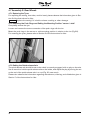
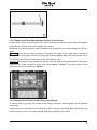
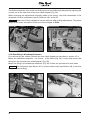
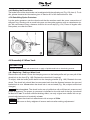
1
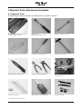
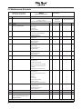
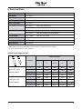
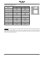
Motus
Service Manual
Service Instructions for the Motus Adaptive Wheelchair
Tabel of contents Page
1 Introduction........................................................................................................................5
1.1 Preface.....................................................................................................................5
1.2 Technical Support....................................................................................................5
2 Safety Instructions.............................................................................................................6
2.1 Explanation of Symbols...........................................................................................6
2.2 General Safety Instructions.....................................................................................6
3 Required Tools, Maintenance Schedule............................................................................7
3.1 Required Tools.........................................................................................................7
3.2 Maintenance Schedule............................................................................................8
4 Settings / Replacement / Retrofit......................................................................................9
4.1 Assembly A: Frame..................................................................................................9
4.1.1 Replacing the Front Frame Part...................................................................................9
4.1.2 Replacing the Rear Frame Part.................................................................................. 10
4.1.3 Replacing the Spacer Sleeve..................................................................................... 12
4.1.4 Replacing / Retrofitting / Setting the Anti-tipper...................................................... 12
4.1.5 Replacing / Retrofitting / Setting Transport Wheels, Crutch Holder, or Tip-assist... 13
4.1.6 Replacing the Support Brackets................................................................................ 14
4.2 Assembly B: Footrest.............................................................................................15
4.2.1 Replacing the Footrest Holder................................................................................... 15
4.2.2 Replacing the Footrest.............................................................................................. 15
4.2.3 Replacing the Lock Piece.......................................................................................... 16
4.2.4 Replacing the Pivot Bearing...................................................................................... 16
4.2.5 Replacing the Swivel Segment.................................................................................. 16
4.2.6 Retrofitting Elevating Footrests................................................................................. 17
4.2.7 Setting the Lower Leg Length.................................................................................... 17
4.2.8 Replacing the Footrest Bar/Footplate....................................................................... 17
4.2.9 Setting or Replacing the Calf Pads........................................................................... 18
4.3 Assembly C: Seat...................................................................................................18
4.3.1 Replacing the Crossbrace......................................................................................... 18
4.3.2 Replacing the Crossbrace Brackets and the Crossbrace Bearing........................... 19
4.3.3 Replacing/Tightening the Seat Upholstery............................................................... 19
4.3.4 Cleaning the Nylon Seat Upholstery.........................................................................20
4.3.5 Cleaning the Standard Seat Cushion........................................................................20
4.3.6 Retrofitting with the Seating System "Adjustable Seat"...........................................20
4.4 Assembly D: Back / Push Handles........................................................................20
4.4.1 Setting the Back Upholstery......................................................................................20
4.4.2 Setting/Replacing the Back Tubes............................................................................ 21
4.4.3 Replacing the Push Handles..................................................................................... 21
4.4.4 Replacing the Rubber Hand Grips.............................................................................22
4.4.5 Cleaning the Nylon Back Upholstery.........................................................................22
4.4.6 Retrofitting the Angle-adjustable Back.....................................................................22
4.4.7 Replacing the Cable of the Angle-adjustable Back..................................................25
4.4.8 Retrofitting with the Back System "The Back"..........................................................25
4.5 Assembly E: Side Panels.......................................................................................26
4.5.1 Replacing / Retrofitting / Setting the Clothing Protector..........................................26
4.5.2 Retrofitting / Setting the Plug-on Side Panels.......................................................... 27
4.5.3 Retrofitting the Desk Side Panels.............................................................................28
4.5.4 Replacement / Length Adjustment of the Armrest...................................................28
4.5.5 Retrofitting a Tray......................................................................................................29
4.6 Assembly F: Casters..............................................................................................29
4.6.1 Caster Trailing Adjustment.........................................................................................29
4.6.2 Replacing the Caster Journal Bearings.....................................................................30
4.6.3 Replacing the Caster Forks....................................................................................... 31
4.6.4 Replacing the Casters............................................................................................... 31
4.7 Assembly G: Rear Wheels......................................................................................32
4.7.1 Replacing the Tyres....................................................................................................32
4.7.2 Replacing the Push Rings and Setting the Mounting Position "narrow / wide"........32
4.7.3 Setting the Quick-release Axle..................................................................................32
4.7.4 Changing the Rear Wheel Adapter Position in the Frame.........................................33
4.7.5 Changing the Position of the Fitting in the Adapter..................................................33
4.7.6 Retrofitting a Wheelbase Extension...........................................................................34
4.7.7 Retrofitting Rear Wheels with Drum Brakes..............................................................35
4.4.8 Setting the Drum Brake.............................................................................................36
4.7.9 Retrofitting Spoke Protectors....................................................................................36
4.8 Assembly H: Wheel Lock.......................................................................................36
4.8.1 Replacing / Setting a Wheel Lock.............................................................................36
4.8.2 Replacing the Wheel Lock Lever...............................................................................37
4.8.3 Replacing the Brake Block........................................................................................38
4.8.4 Retrofitting the Plug-on Wheel Lock Lever Extension...............................................38
5 Technical Data.................................................................................................................39
1 Introduction
1.1 Preface
Regular maintenance is important – it improves the safety and increases the lifespan of the
product.
All Mobility products should be inspected and serviced once a year.
However, if the product is used frequently, or if it is used by growing children or patients with changing clinical conditions, we recommend readjusting and servicing the product every 6 months.
Only use original spare parts for all service and maintenance.
The service and maintenance tasks described here should only be completed by trained, qualified personnel and not by the wheelchair user.
This service and maintenance manual refers to the spare parts catalogues and instructions for
use for the products described. Please use these documents together.
Use the maintenance plan (check list) as a template for making copies. Retain completed maintenance schedules and provide the customer with a copy.
Instructions for use
Motus
647G232=D/GB
Spare parts catalogue
1.2 Technical Support
The Otto Bock Team of your country will be pleased to answer your technical questions. Contact
addresses and telephone numbers are listed on the last page of this manual.
2 Safety Instructions
2.1 Explanation of Symbols
CAUTION
NOTICE
Warnings regarding possible risks of accident or injury.
Warnings regarding possible technical damage.
Information
Information regarding operation. Information for service personnel.
2.2 General Safety Instructions
Information
Please read the service and maintenance instructions before commencing work. Familiarize yourself
with the functions of the product. If you are not familiar with the product, read the instructions for use
before inspecting the product.
If you do not have a copy of the instructions for use, you can order one from the manufacturer (see the
overview of all Otto Bock branches “Otto Bock Worldwide”). You can also download documents from
our homepage: www.ottobock.de or www.ottobock.com.
CAUTION
Risk of injury as a result of inappropriate work clothes. Wear appropriate clothing, including gloves
and protective goggles if required.
NOTICE
Damage caused by using inappropriate tools. Use appropriate tools (refer to page 5).
NOTICE
Damage as a result of unsecured product. Secure the product to prevent it from tipping over or falling off the workbench.
NOTICE
Damage caused by neglected cleaning. Clean or disinfect the product before you start the inspection.
Consult the instructions for use regarding product care or product specific inspection information.
Information
The screws and nuts for many of the screw connections are equipped with thread lock. If you have to
undo such screw connections, replace the nut or screw with a new one equipped with thread lock.
If new screws or nuts with thread lock are not available, apply a medium-strength liquid thread lock
substance (such as Loctite® 241 or Euro Lock A24.20) to the existing screws.
3 Required Tools, Maintenance Schedule
3.1 Required Tools
The following list shows the tools and accessories required for service.
Reversible ratchet handle wrench and
sockets, sizes 8 mm - 21 mm
Torque wrench,
measurement range 5 - 50 Nm
Wrenches, sizes 8 mm - 24 mm *
Allen wrenches, sizes 3 mm - 6 mm*
Screwdrivers, blade width 5 mm
Hammer, approx. 300 g
Stanley knife with standard blade
Pincers and combination pliers
Workbench and vice with plastic jaws
and rubber insert
Folding ruler and level
Liquid thread lock “medium strength”
Inner tube repair kit
* Contained in 481C08=ST010 Tool Set
3.2 Maintenance Schedule
Item
Maintenance schedule
for regular inspections
Motus
- Adaptive Wheelchair -
Component (assembly)
Inspection
Serial number:
1.)
Function / setting
(see 647G232=D/GB Instructions for Use)
(checklist)
2.)
Damage /
deformation
3.)
Screw connections
A
Frame
Frame accessories
· Frame
x
x
B
Footrests
· Folding mechanism
· Lower leg length adjustment
· Angle adjustment
x
x
x
x
x
x
Footrest accessories
C
D
E
Seat
Back / push handles
Side panels
Side panel accessories
F
G
Caster
Rear wheel
Rear wheel accessories
H
Wheel locks
Wheel lock accessories
Do the settings of the wheelchair comply with the user's
requirements?
· Transport wheels
· Anti-tipper
· Tip-assist
· Crutch holder
· Lateral heel blocks
· Heel band
· Crossbrace
· Seat Upholstery
· Seat cushion
· Back upholstery
· Back height
· Angle adjustment
· Push handles
· Height setting
· Swivel mechanism
· Removability
· Armrest padded /swing-away
· Tray
· Tyres (wear)
· Air pressure
· Caster journal angle
· Screw connection to the frame
· Running characteristics of the
wheels
· Swivelling of the caster forks
· Tyres (wear)
· Air pressure
· Running characteristics of the
wheels
· Spokes
· Push rings
· Quick-release axles
· Wheel camber
· Rear wheel attachment device
· Drum brake
· One-arm drive
· Wheelbase extension
· Spoke protector
· Brake function
· Wheel lock lever extension
The maintenance service was carried out by:
Customer:
x
x
x
x
x
x
x
x
x
x
x
x
x
x
x
x
x
x
x
x
x
x
x
x
x
x
x
x
x
x
x
x
x
x
x
x
x
x
x
x
x
x
x
x
x
x
x
x
x
x
x
x
x
x
x
x
x
x
x
x
x
x
x
x
on:
x
x
x
x
x
x
x
4 Settings / Replacement / Retrofit
4.1 Assembly A: Frame
4.1.1 Replacing the Front Frame Part
First remove the rear wheels (Fig. 1). Place the unfolded wheelchair on its side on a flat work
surface. Grasp into the pivot lever and remove the footrests (Fig. 2).
Undo and remove the screws of the caster wheel mountings and take the mountings off with the
forks and caster wheels still attached to them (Fig. 3).
Undo the screws of the front support brackets and remove them (Fig. 4).
1
3
2
4
Loosen and remove the screws at the upper frame tube (Fig. 5). Loosen and remove the screws
on the inside of the wheel lock clamp fitting (Fig. 6).
You can now pull off the frame part to the front (Fig. 7).
Loosen and remove the screw connection of the clamp fitting and remove the wheel lock
(Fig. 8).
Replace the front frame part. For assembly, please proceed in reverse order.
Use new screws coated with thread lock for assembling the caster assembly. When
attaching the caster mountings, be sure to tighten them to the indicated torque values (see Section 4.6).
Information
5
7
6
8
4.1.2 Replacing the Rear Frame Part
First remove the rear wheels. Loosen and remove the four screws at the rear wheel adapter
(Fig. 9) and remove the adapter.
If applicable, loosen and remove the screw connection between the side panel and back tube
(Fig. 10).
10
9
10
Loosen and remove the screw connection at the upper frame tube (Fig. 11) as well as at the
lower frame tube (Fig. 12). Slightly fold the wheelchair and remove the rear support bracket.
Remove the seat padding from the backrest and open the hook and loop straps of the back
upholstery. Pull the back tube out of the rear frame part (Fig. 13).
Pull off the rear frame part to the rear (Fig. 14). You can now easily access and remove all the
accessory items mounted to the rear frame parts.
Replace the rear frame part. For assembly, please proceed in reverse order.
Information
adapters.
Use new screws coated with thread lock for assembling the frame and the rear wheel
11
13
12
14
11
4.1.3 Replacing the Spacer Sleeve
Loosen and remove the two screw connections between the side panels and frame tube
(Fig. 15).
You can now pull the spacer sleeve to the front off the joint tub (Fig. 16).
Replace the spacer. For assembly, please proceed in reverse order.
15
16
4.1.4 Replacing / Retrofitting / Setting the Anti-tipper
1. Mount the receiver tube to the frame in the position shown (Fig. 17).
2. Slide the anti-tipper from below into the mounted receiver tube. Tighten the screw connection
of the anti-tipper in the uppermost position of the receiver tube as shown (Fig. 18).
. Adjust the anti-tipper with the length adjustment (Fig. 19).
. By changing the screw connection in the receiver tube, the anti-tipper can be horizontally
adjusted. The anti-tipper wheel must at least completely extend from the rear wheel to the
back, and the distance between the wheel and ground should not exceed 5 cm maximum.
17
12
18
19
4.1.5 Replacing / Retrofitting / Setting Transport Wheels, Crutch Holder, or Tip-assist
Mount the receiver tube for transport wheels, crutch holder, or tip-assist on the inside of the
frame tube as shown (Fig. 20).
The receiver tube for the anti-tipper has a slightly different design and cannot be used
for these options.
Information
Insert the sleeve provided from below into the receiver tube (Fig. 21). Slide the desired accessory
item into the receiver tube until it audibly snaps into place (Fig. 22).
If using the crutch holder, an additional hook and loop strap is to be attached to the
upper back tube. To do this, loosen and remove the uppermost screw at the back tube. Position
the hook and loop strap between the screw and back tube (Fig. 22A) and retighten the screw.
Information
20
21
13
22
22 A
4.1.6 Replacing the Support Brackets
Fix the wheel lock. Slightly fold the wheelchair (Fig. 23). Loosen and remove the oval head screw
at the support bracket (Fig. 24) and pull the bracket up to remove it. Replace the support bracket.
For assembly, please proceed in reverse order.
Replacement of the rear support bracket takes place correspondingly in the same way. Recommendation: Remove the rear wheel first (Fig. 25).
23
25
14
24
4.2 Assembly B: Footrest
Information
Use new screws coated with thread lock or apply a liquid thread lock to the existing screws.
4.2.1 Replacing the Footrest Holder
Insert the footrest holders – in laterally turned position – from above into the front frame tubes
(Fig. 26).
Turn the footrest holders to the front until the swivel segment engages with the lock. For disassembly, please proceed in reverse order.
For adjusting the lower leg length and for operation, please observe the information given in the
Instructions for Use.
26
4.2.2 Replacing the Footrest
Remove the footrest holder. Loosen and remove the lower set screw on the inside of the swivel
segment (Fig. 27).
Loosen the upper set screw until the footrest bar can be moved (Fig. 28). Then pull the footrest
bar downwards out of the swivel segment.
Replace the footrest. For assembly, please proceed in reverse order.
27
28
15
4.2.3 Replacing the Lock Piece
Remove the footrest holder. Loosen and remove the screw of the lock piece (Fig. 29) and remove
the lock piece.
Replace the lock piece. For assembly, please proceed in reverse order.
4.2.4 Replacing the Pivot Bearing
Remove the footrest from the footrest holder. Loosen and remove the screw of the pivot bearing
(Fig. 30) and remove the pivot bearing.
Replace the pivot bearing. For assembly, please proceed in reverse order.
29
30
4.2.5 Replacing the Swivel Segment
Remove the footrest from the footrest holder. Loosen and remove the screw of the swivel segment (Fig. 31) and remove the swivel segment (Fig. 32).
Replace the swivel segment. For assembly, please proceed in reverse order.
31
16
32
4.2.6 Retrofitting Elevating Footrests
Remove the footrest holder from the front frame. Remove the lock piece (Fig. 29).
Put the provided lock piece of the elevating footrest onto the front frame and tighten the screw
connection with the screws provided (Fig. 33).
Mount the pre-assembled elevating footrest to the front frame in the same way as the standard
footrest (Fig. 34).
33
34
4.2.7 Setting the Lower Leg Length
After loosening the set screw, the footrest bar can be adjusted or completely pulled out of the
footrest holder (Fig. 35).
4.2.8 Replacing the Footrest Bar/Footplate
First remove the footrest from the swivel segment as described in Section 4.2.2.
Flip up the footplate. Loosen and remove the two screws on the outside of the footplate. Make
sure that the lower screw is provided with a counter nut (Fig. 36).
35
36
Loosen and remove the screw on the front of the footplate (Fig. 37). Now you can remove the
footrest bar from the footplate and replace with new ones, if necessary.
17
4.2.9 Setting or Replacing the Calf Pads
Loosen and remove the screw of the calf pad and remove the pad (Fig. 38).
Replace the calf pad. For assembly, please proceed in reverse order.
The slotted holes in the calf pad retainer plate allow for sideways adjustments of the
calf pad (Fig. 38, see arrows).
Information
37
38
4.3 Assembly C: Seat
Information
Use new screws coated with thread lock or apply a liquid thread lock to the existing screws.
4.3.1 Replacing the Crossbrace
First remove the front frame parts as described in Section 4.1.1. You do not need to detach the
wheel locks. Then remove the spacers as described in Section 4.1.3.
Place the wheelchair frame on its rear frame parts and push handles. Pull the sleeves out of the
lower crossbrace tubes (Fig. 39).
Grasp the crossbrace and pull it up off the joint tubes (Fig. 40).
Replace the crossbrace. For assembly, please proceed in reverse order.
Removal of the crossbrace will separate the rear frame parts from each other. Carefully lay the rear frame parts onto the work surface once removed.
Information
18
39
40
4.3.2 Replacing the Crossbrace Brackets and the Crossbrace Bearing
After removing the crossbrace from the joint tube, remove the clips of the crossbrace brackets
(Fig. 41) and pull the screw off to the rear.
Replace the crossbrace bracket. For assembly, please proceed in reverse order.
To replace the crossbrace bearing, lay the crossbrace onto the upholstery. Loosen and remove
the central screw connection of the crossbrace (Fig. 42).
Replace the crossbrace bearing. For assembly, please proceed in reverse order.
41
42
4.3.3 Replacing/Tightening the Seat Upholstery
First remove the two footrest holders. Remove the seat cushion. Remove the front tube end caps
using a (not too sharp-edged) screwdriver (Fig. 43).
If the wheelchair is unfolded, slightly fold it to reduce the tension on the seat upholstery and then
pull the seat upholstery out of the crossbrace's profile tubes (Fig. 44).
Replace the seat upholstery and upholstery bars, if necessary.
A hook and loop closure on the underside (Fig. 45) can be used to tighten the seat upholstery
as desired.
For assembly, please proceed in reverse order.
19
4.3.4 Cleaning the Nylon Seat Upholstery
Clean the seat upholstery with regular mild household cleaner.
4.3.5 Cleaning the Standard Seat Cushion
Open the zipper and remove the foam core (Fig. 46). Clean the cushion cover according to the
sewn in care instructions label.
43
45
44
46
4.3.6 Retrofitting with the Seating System "Adjustable Seat"
Please observe the information given in the product's Instructions for Use 647H450.
4.4 Assembly D: Back / Push Handles
Information
Use new screws coated with thread lock or apply a liquid thread lock to the existing screws.
4.4.1 Setting the Back Upholstery
You can adjust the back upholstery in segments according to your needs.
To do this, remove the back upholstery padding (Fig. 47) and undo the hook-and-loop fasteners
of the straps (Fig. 48).
20
Reposition the straps as desired, attach them again with the hook-and-loop fasteners, and cover
with the padding.
47
48
4.4.2 Setting/Replacing the Back Tubes
The back tube which is integrated into the rear frame allows for the adjustment of the back height
in increments of 2.5 cm.
If applicable, loosen and remove the screw connection between the side panel and back tube
(Fig. 49). Remove the mounting clamps from the back tube (Fig. 50).
Remove all screws from the rear frame tube including the screw connection of the rear wheel
adapter (Fig. 51) and set the desired back height. For assembly, please proceed in reverse
order.
When making adjustments, ensure that the back tube is slid at least 79 mm into the
rear frame tube. Make sure to firmly retighten all screws and nuts after making adjustments!
Information
4.4.3 Replacing the Push Handles
Loosen and remove the two screws at the upper back tube (Fig. 52). Pull the push handles up
out of the tube.
Replace the push handles. For assembly, please proceed in reverse order.
49
50
21
51
52
4.4.4 Replacing the Rubber Hand Grips
Carefully cut open the rubber hand grip (Fig. 53). Remove the old rubber hand grip. Remove the
residue of the old glue or rubber from the tube and clean the tube ends with solvent.
Open the two part adhesive sachet. Observe the instructions given by the manufacturer of the
adhesive.
Use the spatula to squeeze out all the contents of the sachet into the centre of the mixing card.
Mix the adhesive using the spatula.
Ensure you work effectively after mixing, since the adhesive sets quite quickly. Apply half of the
adhesive into each of the rubber hand grips using the spatula (Fig. 54). Evenly distribute the
adhesive in the rubber hand grip up to a depth of approx. 4–5 cm. Slide the rubber hand grips
onto the push handles rotating them slightly as they are pushed on.
Information
Now wait for at least 24 hours so as to allow full curing of the adhesive.
53
54
4.4.5 Cleaning the Nylon Back Upholstery
Clean the back upholstery with regular mild household cleaner.
4.4.6 Retrofitting the Angle-adjustable Back
Information To be able to use the angle-adjustable back, plug-on side panels must have been
mounted.
22
Remove the back upholstery padding (Fig. 55). On both sides, loosen and remove the rear screw
connections of the rear wheel adapter from the frame tubes (Fig. 56). Now pull the back part
up out the frame tubes (Fig. 57).
Insert the insert sleeves provided into the rear frame tubes (Fig. 58). Insert the adjustment elements into the insert sleeves (Fig. 59).
Screw the rear wheel adapter to the rear frame and fix the adjustment element to the rear frame
with the screws A provided (Fig. 60).
55
57
59
56
58
60
23
Pull the new back upholstery onto the back tubes provided and tighten the screw connections
(Fig. 61). Push the rubber hand grips onto the back tubes using a lubricant (Fig. 62). Connect
the two rubber hand grips with the back stabilizer provdided (Fig. 63).
Put the pre-assembled back unit onto the adjustment elements (Fig. 64). Pull the back upholstery up and tighten the screw connections between the back tubes and adjustment elements
(Fig. 65).
Thread the cable through the key rings. Form the cable ends to eyelets and push on the aluminium
sleeves provided (Fig. 66). Squeeze the aluminium sleeves using combination pliers (Fig. 67).
61
63
24
62
64
65
66
67
4.4.7 Replacing the Cable of the Angle-adjustable Back
On both sides, cut the damaged cable in two using pincers (Fig. 68). To mount the new cable,
please proceed as described in Section 4.4.5.
68
4.4.8 Retrofitting with the Back System "The Back"
Please observe the information given in the product's Instructions for Use 647H491.
25
4.5 Assembly E: Side Panels
4.5.1 Replacing / Retrofitting / Setting the Clothing Protector
First remove the rear wheel. Loosen and remove the screw connection between the side panel and
back tube (Fig. 69). Loosen and remove the two screw connections between the side panel and
frame (Fig. 70). You can now remove the side panel. Replace the side panel, if necessary.
The new side panel is attached to the front frame tube with two screws and attached to the back
tube with one screw and a plastic clamp.
Use the array of screw-holes to set the side panel height, so the top panel edge is around 25 mm
higher than the wheels and so fingers can’t get trapped in the gap (Fig. 71). If you want to change
from desk side panels to the side panels mentioned here you will also need the mounting kit
481A45=SW048.
69
25 mm
71
26
70
4.5.2 Retrofitting / Setting the Plug-on Side Panels
First remove the clothing protector as described in Section 4.5.1. Remove the anterior screw
from the rear frame part (Fig. 72).
Attach the holder for the plug-on side panel – as shown – to the frame and tighten the screw
connection (Fig. 73). Insert the plug-on side panel from above into the holder (Fig. 74).
For height adjustment of the side panel, press the counter-sunk locking button using a ball point
pen / key / screwdriver, etc. (Fig. 75). Move the side panel into the desired position.
CAUTION
Risk of pinching. The locking button is counter-sunk to prevent accidental operation. Always use an
object to press the locking button; never use your fingers.
72
74
73
75
27
4.5.3 Retrofitting the Desk Side Panels
First remove the clothing protector as described in Section 4.5.1. Remove the two screws from
the rear frame part.
Attach the holder for the desk side panel – as shown – to the frame and tighten the screw connection (Fig. 76). Then attach the pivot bearing to the uppermost bore hole in the rear frame so
that the form fits and tighten the screw connection. From above and in vertical position, insert
the desk side panel into the pivot bearing (Fig. 77).
Then let it engage forwards into the holder.
76
77
4.5.4 Replacement / Length Adjustment of the Armrest
Loosen and remove the two screws underneath the armrest (Fig. 78) and remove the armrest.
There are five bore holes on the underside of the armrest that are used to adjust the armrest
(Fig. 79).
Position the armrest as needed and firmly retighten the screws.
78
28
79
4.5.5 Retrofitting a Tray
To be able to use a tray in matching seat width, desk side panels or plug-on side panels must
have been mounted to the Motus.
Pull the protective foil off the tray and evenly slide the tray onto the armrests (Fig. 80). The use
of tools in not required.
80
4.6 Assembly F: Casters
Information
Use new screws coated with thread lock or apply a liquid thread lock to the existing screws.
4.6.1 Caster Trailing Adjustment
After the rear wheels have been mounted, the caster wheel journal angle must be readjusted. The
threaded axle should be as horizontal as possible in relation to the ground to ensure optimal driving behaviour of the wheelchair. The caster adapter allows for continuous angle adjustment.
Pull the cover cap off the caster journal bearing using a screwdriver (Fig. 81). Next, remove the
protective cap from the screw connection of the inner frame side (Fig. 82).
Slightly loosen the rear screw connection – as shown – (Fig. 83).
Open the screw connection of the eccentric. Place the level on the caster wheel journal and
adjust the eccentric using a screwdriver (Fig. 84). Firmly retighten all screw connections and
reattach the caps.
Information
The correct torque of the screws is 8 Nm.
29
81
83
82
84
4.6.2 Replacing the Caster Journal Bearings
Remove the dust protection cap from the caster journal (Fig. 85). Place the wheelchair on its
push handles.
Loosen and remove the threaded axle from the caster journal (Fig. 86). The deep groove ball
bearings are below the screw connection in the caster journal. Replace the bearings with new
ones. For assembly, please proceed in reverse order. Firmly retighten the screw connection.
85
30
86
4.6.3 Replacing the Caster Forks
Place the wheelchair on its push handles.
First undo and remove the nut above the caster mounting (Fig. 87). Pull the fork with the axle
out of the ball bearings. Next, loosen and remove the nut at the lower end of the threaded axle.
Replace the caster fork. For assembly, please proceed in reverse order. Firmly retighten the
screw connection.
87
4.6.4 Replacing the Casters
The anterior seat height is set via the row of holes in the fork and via the caster wheel diameter.
To do this, please refer to the seat height table in the Instructions for Use.
Loosen the screw connection on the casters (Fig. 88) and remove the wheels from the fork.
For reassembly, please proceed in reverse order. Firmly retighten the screw connection.
The casters must be replaced, if the material shows signs of cracking or damage and
when the tread becomes worn down to such an extent that there is only 5 mm of radius left on
the outer edges of the tyre.
Information
Replace the casing of weels with pneumatic tyres if it is bald or shows signs of cracking or other damage.
Information
88
31
4.7 Assembly G: Rear Wheels
4.7.1 Replacing the Tyres
For replacing the casing, inner tube, and rim band, please observe the information given in Section 8 of the Instructions for Use.
Information
Replace the casing if it is bald or shows cracking or other damage.
4.7.2 Replacing the Push Rings and Setting the Mounting Position "narrow / wide"
Completely remove the tyre.
Loosen and remove the screw connection of the push rings with the rim.
Mount the push rings in the narrow or wide mounting position in relation to the rim (Fig 89).
For mounting the tyres, please refer to Section 8 of the Instructions for Use.
89
4.7.3 Setting the Quick-release Axle
The quick-release axle should be set so the wheel is correctly engaged, with no play on the axle.
Use a wrench to hold the quick-release axle on the inside, and adjust the play by turning the nut
on the end of the quick-release axle in or out (Fig. 90, see arrow).
Please also observe the information regarding maintenance, cleaning, and disinfection given in
Section 7 of the Instructions for Use.
32
90
4.7.4 Changing the Rear Wheel Adapter Position in the Frame
Loosen all four screw connections (Fig. 91, see arrows) and remove the screws. Move the adapter
to the desired position and firmly retighten the screws.
Additional rear wheel positions can be obtained by turning the rear wheel adapter by 180 degrees.
When the rear wheel position is changed, the angle of the caster axle in relation to
the ground also changes. Ensure that this angle is always approx. 90° wide (see Section 4.6.1).
The wheel lock must be re-adjusted as well (see Section 4.8.1).
Information
Make sure to firmly retighten all screws and nuts after making adjustments. The proper
torque for the screw connection of the rear wheel adapter is 8 Nm. The proper torque for the
screw connection of the fitting is 50 Nm.
Information
91
4.7.5 Changing the Position of the Fitting in the Adapter
To set the centre of gravity, the position of the fitting in the rear wheel adapter can be adjusted
horizontally.
Loosen the screw connection of the fitting (Fig. 92) and remove the fitting. Move the fitting to the
desired position in the rear wheel adapter and firmly retighten the screws.
33
The distance between rear wheel and side panel can be continuously adjusted by adjusting the
counter nut on the outer side of the rear wheel adapter (Fig. 93).
When changing the adjustments originally made in the factory, two other assemblies of the
wheelchair must be readjusted, refer to Sections 4.6.1 and 4.8.1.
Make sure to firmly retighten all screws and nuts after making adjustments. The proper
torque of the screw connection of the rear wheel adapter is 8 Nm.
Information
92
93
4.7.6 Retrofitting a Wheelbase Extension
First remove the rear wheels. Remove the rear wheel adapter as described in section 4.7.4.
Mount the wheelbase extension – as shown – to the frame (Fig. 94). Loosen and remove the
fitting from the removed rear wheel adapter (Fig. 95).
Mount the fitting in the wheelbase extension (Fig. 96). Follow this procedure on both sides.
The side panels (see Section 4.5.1) and the wheel locks (see Section 4.8.1) are to be
re-adjusted accordingly.
Information
94
34
95
96
97
4.7.7 Retrofitting Rear Wheels with Drum Brakes
To be able to mount wheels with drum brakes you first have to replace the standard quick-release
axle housing with the provided bushing and brake anchor (Fig. 97).
For attachment of the brake handle, the push handle must be equipped with an extension (Fig. 98).
First remove the rubber hand grips (see Section 4.4.3). Mount one handle extension on each
side. You can now mount the brake handles to the push handles (Fig. 99).
Lay the cables from the brake handle to the brake drum. For setting the drum brakes, please
observe the information given in the Instructions for Use.
98
99
35
4.4.8 Setting the Drum Brake
The brake force of the drum brake can be adjusted with the adjusting nut (Fig. 100, item 1). To do
this, please observe the information given in Section 6.5 of the Instructions for Use.
4.7.9 Retrofitting Spoke Protectors
Lay the spoke protector onto the wheel such that the notches match the screw connections of
the push ring. Starting with a round hole press on the spoke protector with an attachment nipple. We recommend using a hammer shaft for this work step (Fig. 101). Press all nipples onto
the spokes, one after the other.
100
101
4.8 Assembly H: Wheel Lock
Information
Use new screws coated with thread lock or apply a liquid thread lock to the existing screws.
4.8.1 Replacing / Setting a Wheel Lock
Remove the rear wheel. Loosen the clamping screw on the brake profile until you can pull off the
wheel lock to the front (Fig. 102). Replace the wheel lock if required.
To adjust, slide the brake profile back into the clamping element (Fig. 103). Reattach the rear
wheel. The wheel lock should then be remounted such that the distance between the tyre and
brake block is max. 10 mm when the wheel lock is not activated (Fig. 104; subject to technical
changes).
CAUTION
Risk of accident. The wheel locks are only effective with sufficient air pressure and
proper adjustment. The proper air pressure is indicated on the side wall of the tyre, but should
at least be 7 bar. To ensure sufficient braking effect, use only original rear wheels with an approved radial excursion of maximally ±1 mm.
Information
Information
36
Tighten the wheel lock attachment with a torque of 5 Nm.
Make sure to firmly retighten all screws and nuts after making adjustments!
4.8.2 Replacing the Wheel Lock Lever
Disassemble the wheel lock as described in Section 4.8.1.
Loosen the two screws in the wheel lock housing (Fig. 105) and remove the housing.
Remove the wheel lock lever. Replace the whel lock lever. For assembly, please proceed in
reverse order.
102
104
103
105
37
4.8.3 Replacing the Brake Block
Loosen and remove the screw connection on the inner side of the brake block (Fig. 106) and
remove the brake block. Replace the brake block and reassemble it.
4.8.4 Retrofitting the Plug-on Wheel Lock Lever Extension
Carefully cut open the rubber grip of the wheel lock lever (Fig. 107) and remove the rubber
grip.
Screw the cord of the wheel lock lever extension to the pre-drilled hole in the wheel lock housing
using the screw provided (Fig. 108).
Remove any residues of old glue or rubber from the wheel lock lever. Plug the wheel lock lever
extension onto the wheel lock lever (Fig. 109).
106
108
38
107
109
5 Technical Data
Seat width:
Seat depth:
Back height:
Back angle:
Lower leg length:
Seat heights:
35.5 – 55.5
36.0 – 54.0
30.0 – 50.0
settings of up to -30° are possible
34.0 – 54.0
42.5 – 49.0
with short caster fork
52.0 – 72.0
with standard rear wheels*
46.0 – 53.0
Overall width:
55.5 – 75.5
Overall length:
80.5 – 108.5
83.0 – 111.0
Weight:
Load capacity:
approx. 13 kg
with long caster fork
with rear wheels with drum brake*
with 22” rear wheel
with 24” rear wheel
125 /140 kg
* Applicable to push ring attachment, narrow, and a 0° camber of the rear wheels
(for push ring attachment, wide: +20 mm).
Anterior seat height (in cm)
Caster diameter
Position
4“
4
Caster fork, short
(481F00-SS072)
3
42.5
1
45.5
2
4
Caster fork, long
(481F00-SS070)
43.5
5“
140 mm
6“
45.0
46.0
46.0
46.0
47.0
47.5
46.0
3
46.0
47.5
1
48.5
50.0
2
47.5
49.0
47.0
48.0
50.0
51.5
7“
48.0
49.0
49.0
50.0
50.0
51.0
49.0
51.0
53.0
39
Posterior seat height (in cm)
Position
Rear wheel size
22“
24“
1
36.0
38.5
3
38.5
41.0
2
4
5
37.0
40.0
41.0
6
42.0
8
44.5
7
9
10
11
12
43.5
46.0
47.0
48.5
50.0
40.0
DCBA
42.5
43.5
44.5
46.0
47.5
48.5
49.5
51.0
52.0
The values indicated are measurements which have been theoretically determined.
Not all adjustment possibilities can be used for all wheelchair models. Further, the adjustment
combinations are limited due to the sturdy frame geometry. We reserve the right to technical
alterations and deviations by 5%.
Information
40
41
42
Hersteller/Manufacturer:
Otto Bock HealthCare GmbH
Max-Näder-Straße 15 · 37115 Duderstadt/Germany
National: Telefon (0 55 27) 848 1461/1462/1463 · Fax (0 55 27) 848 1460
International: Phone +49-5527-848-1590 · Fax +49-5527-848-1676
e-mail: [email protected] · Internet: http://www.ottobock.com
Otto Bock HealthCare GmbH
Lindenstraße 13 · 07426 Königsee/Germany
Otto Bock HealthCare GmbH has been certified by the German Society for the Certification of Quality Assurance Systems (DQS)
in accordance with DIN EN ISO 9001 standard, reg. no. 779 (management system)
© Otto Bock · 647G233=GB – 05.08/1
Versandanschrift für Rücksendungen/Address for Returns