1
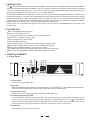
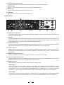
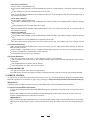
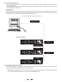
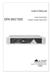
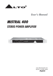
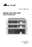
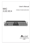
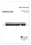
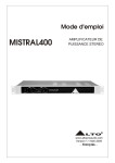
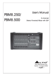
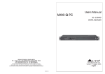
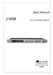
User's Manual
40 BIT ENHANCED
DPA 2500/4000
STEREO POWER AMPLIFIER
R
LTO
www.altoproaudio.com
Version 1.0 September 2004
English
the recommended fuse type as indicated in this
manual. Do not short-circuit the fuse holder. Before
replacing the fuse, make sure that the product is
OFF and disconnected from the AC outlet.
SAFETY RELATED SYMBOLS
CAUTION
RISK OF ELECTRIC SHOCK
DO NOT OPEN
Protective Ground
This symbol, wherever used, alerts you to the presence of un-insulated and dangerous voltages within the product enclosure. These are voltages that
may be sufficient to constitute the risk of electric
shock or death.
Before turning the product ON, make sure that it is
connected to Ground. This is to prevent the risk of
electric shock.
Never cut internal or external Ground wires. Likewise,
never remove Ground wiring from the Protective
Ground Terminal.
This symbol, wherever used, alerts you to important operating and maintenance instructions.
Please read.
Operating Conditions
Always install in accordance with the manufacturer's
instructions.
Protective Ground Terminal
Denotes the product is turned on.
To avoid the risk of electric shock and damage, do
not subject this product to any liquid/rain or moisture.
Do not use this product when in close proximity to
water.
OFF: Denotes the product is turned off.
Do not install this product near any direct heat source.
WARNING
Do not block areas of ventilation. Failure to do so
could result in fire.
AC mains (Alternating Current)
Hazardous Live Terminal
ON:
Describes precautions that should be observed to
prevent the possibility of death or injury to the user.
Keep product away from naked flames.
IMPORTANT SAFETY INSTRUCTIONS
CAUTION
Read these instructions
Describes precautions that should be observed to
prevent damage to the product.
Follow all instructions
Keep these instructions. Do not discard.
WARNING
Heed all warnings.
Power Supply
Only use attachments/accessories specified by the
manufacturer.
Ensure that the mains source voltage (AC outlet)
matches the voltage rating of the product. Failure
to do so could result in damage to the product and
possibly the user.
Power Cord and Plug
Do not tamper with the power cord or plug. These are
designed for your safety.
Unplug the product before electrical storms occur
and when unused for long periods of time to reduce
the risk of electric shock or fire.
Do not remove Ground connections!
If the plug does not fit your AC outlet seek advice from
a qualified electrician.
External Connection
Always use proper ready-made insulated mains
cabling (power cord). Failure to do so could result
in shock/death or fire. If in doubt, seek advice from
a registered electrician.
Protect the power cord and plug from any physical
stress to avoid risk of electric shock.
Do Not Remove Any Covers
Cleaning
Within the product are areas where high voltages
may present. To reduce the risk of electric shock do
not remove any covers unless the AC mains power
cord is removed.
When required, either blow off dust from the product
or use a dry cloth.
Do not place heavy objects on the power cord. This
could cause electric shock or fire.
Do not use any solvents such as Benzol or Alcohol.
For safety, keep product clean and free from dust.
Covers should be removed by qualified service
personnel only.
Servicing
Refer all servicing to qualified service personnel only.
No user serviceable parts inside.
Do not perform any servicing other than those instructions contained within the User's Manual.
Fuse
To prevent fire and damage to the product, use only
1
PREFACE
Dear Customer:
Thanks for choosing
endeavors.
For
LTO DPA2500/4000 Stereo Power Amplifier which is the result of our
LTO AUDIO TEAM's
LTO AUDIO TEAM, music and audio are much more than a job, they are a passion and an obsession!
We have been designing professional audio products for a long time in cooperation with many of the world's
major brands.
The LTO line represents unparalleled analogue and digital products made by musicians, for musicians. With our
design centres in Italy, the Netherlands, and the United Kingdom we provide you with world-class designs, while our
software development teams continue to develop an impressive range of audio specific algorithms.
By purchasing our LTO products you become the most important member of our LTO AUDIO TEAM. We would like to
share with you our passion for what we design and we invite you to make suggestions, which will aid us in developing
future products for you. We guarantee you our commitment to quality, continual research and development, and of course
the best performance/price ratio.
Our LTO DPA2500/4000 Stereo Power Amplifier is the result of many hours of listening and tests involving
common people, area experts, musicians and technicians. The result of this effort is the sophisticated circuit design
featuring high power and superb quality together with superior reliability and stability to provide the highest possible
audio performance.
We would like to thank all the people that worked with us to make a vision real! Our designers and LTO staff
made the DPA2500/4000 Stereo Power Amplifier, a very reliable and high quality product ready for all your
venues. And thanks to their passion for music and professional audio it has been possible for us to offer you,
our most important team member, our continued support too.
Thank you very much.
LTO AUDIO TEAM
2
TABLE OF CONTENTS
1. INTRODUCTION.....................................................................................................................................4
2. FEATURES.............................................................................................................................................4
3. CONTROL ELEMENTS..........................................................................................................................4
3.1 The Front Panel
3.2 The Rear Panel
4. GETTING STARTED................................................................................................................................6
4.1 Preset Selection
4.2 Edit Menu
4.3 Channel Selection
4.4 Comm Selection:
4.5 SIG/LIMITER LED
5. REMOTE CONTROL ...............................................................................................................................7
5.1 How to set the DPA's ID number
5.2 Connection to the PC
5.3 First Steps with the PC Editor
5.4 Edit Mode (Password Protection)
5.5 Help File
5.6 Introduction to the PC Editor
6. PARAMETER MENUS DESCRIPTION .................................................................................................11
7. WORKING WETH PRESETS..................................................................................................................11
8. CONNECTIONS...........................................................................................................................................12
9. APPLICATION.......................................................................................................................................13
9.1 Stereo Mode
9.2 Bridge Mode
10. TECHNICAL SPECIFICATIONS...........................................................................................................17
11. WARRANTY..........................................................................................................................................18
3
1. INTRODUCTION
The LTO DPA2500/4000 40 Bit DSP Stereo Amplifier is a high power, low profile, professional Power Amplifier
with advanced features and great reliability. In fact, the amplifier functions far beyond a traditional power amplifier,
it is also a versatile effect processor. You can set the input and output audio configuration through recalling one
of the presets included in the internal memory or PC editor software.
The amplifier delivers tremendous power in only two rack spaces, providing high performance under the most
demanding conditions. It contains two independent channels, with separate AC transformer secondaries, power
supplies and protection system. All protection systems, except the main AC one, are self resetting upon removal
of fault, and the remaining channels shall continue to operate. Each channel has independent protective circuitry
against open circuit, short circuit, mismatched loads and over temperature.
Thanks to the use of selected and expensive components, the performance of DPA2500/4000 is worth much more
than its price.
2. FEATURE LIST
Built in 40-bit digital effect processor.
Remote control through PC link
1 factory preset and 32 user presets by large memory capacity
Delay lines up to 582ms for each output
Easy to operate front panel controls
User-controllable clip limiter.
Stereo (dual channel), or bridge mono (bi-amp output) operation mode.
Balanced XLR inputs/parallel outputs to ensure noiseless long wiring.
Binding post and Neutrik Speakon connectors for outputs.
Front panel LED indicators for operating/protection, limiter, power and clip.
Manufactured under QS9000, VDA6.1 certified management system.
3. CONTROL ELEMENTS
3.1 Front Panel
32
7
45
8 9
DPA 4000
ON
CH1
CH2
CLIP
PRESET
OPERATING/
PROTECTION
OFF
POWER
1
POWER ON
VOLUME
EDIT
HUM CANCEL
CHSEL
COMM
LIMIT
88
UP
NOISE GATE
MULTICOMP
SIG/LIMITER
DOWN SELECT ENTER
R
LTO
40 BIT DSP ENHANCED
Stereo Power Amplifier
6
1. Power Switch
Turn the unit power ON or OFF.
2. Clip LED
When the signal distortion reaches or surpasses 0.5%, the LED lights up. This means the output level of
signal source is too high and it is time to reduce input level until clip LED turns off.
3. Output Limiter LED
While the unit is limiting the output signal, the LED lights up.
4. Operating and Protection LED
In normal operation, the LED is green, if the LED is red, it means the unit is in heat protection, no signal output at
the time and over-heat inside the unit (the surface temperature of power transistor is over 100 ), the temperature
must be lowered through better ventilation and decrease the signal level etc. After the temperature has dropped, the protection stops and meanwhile the LED turns off with the unit recover normal work.
5. Power LED
This LED lights up when the unit is powered.
4
6. Level Control for Channels 1&2
These two controls are used to adjust output level of channel 1 and channel 2 respectively.
7. UP/DOWN Key
This key is used to move inside the menus or to modify the parameter's value.
8. SELECT Key
This key is used to select the menu that you wish to edit.
9. ENTER Key
This key is used to edit or confirm the parameter's value.
3.2 Rear Panel
14
11
18 19
POWER OUTPUTS
Apparaten skall anslutas
till jordat uttag nar den
ansluts till ett natverk
CH1
1+
1POS NEG
CH2
INPUT
2
CH2
2
1
INPUT
INPUT
INPUT
TIP/PIN 2
RING/PIN 3
SLEEVE/PIN 1
CH1
2
1
2
1
3
MODE
PARALLEL
OUTPUT
15
STEREO
BRIDGE
2+
POS
1
3
CH1
2NEG
BRIDGE
1+
2+
POS NEG
TIP/PIN 2
RING/PIN 3
SLEEVE/PIN 1
BREAKER
OUTPUT1
RS485 IN
BRIDGE
MONO
CH2
1+
1POS NEG
RS485 OUT
CH2
LIMITER
BALANCED
INPUT
16
BALANCED
INPUT
17
OFF
ON
PARALLEL
OUTPUT
13 15
RS232
OUTPUT2
SERIAL PORT
12
10
20
10. Power Source Socket
It is used to connect power cord after setting the proper voltage, connect one end of power cord with the unit
and another end with mains.
11. Breaker
This switch functions as fuse for protecting the unit from damage. When the unit is overloaded or the
temperature inside the unit is too high, this pushing button will spring up and break the power supply. The
power supply will be recovered after pushing this switch down again.
12. Output Connector
These connectors have two kinds: Binding post and Speak-on connector. You can choose proper connectors
according to practical need. For your safety, please be careful when do connecting work.
13. Limiter Switch
Set this switch at "ON" position, once the output level is above maximum output level, the limiter begins,
thus keeping consistent output level for protecting apparatus. If the switch is set at "OFF", the limiter function
doesn't work.
14. Balanced Input Connectors
These connectors connect the input signal of channel 1 and channel 2 separately.
15. Parallel Output Connectors
These two output connectors are paralleled inside with the two input connectors. It enables the unit to work under
paralleled mode. Please also refer to wiring diagram for paralleled mode.
16. Mode Selector
Total two optional modes: Up for Stereo mode; Down for Bridge mode.
- Stereo Mode
In this mode, channel 1 and channel 2 operate independently (just as traditional stereo amplifier). The signal
input into channel 1 can be output from channel 1 only, similarly, the signal input into channel 2 can be output
from channel 2 only.You can also operate the paralleled mode via outside wiring, so, the signal input from
channel 1 or 2 will be output from both channel 1 and 2 simultaneously. Details refer to the chapter 9.
- Bridge Mode
In this mode, the signal input into channel 1 will be output from the bridged end, on the other hand, the
output level control of channel 2 should be turned down to smallest.Details refer to the chapter 9.
5
17. Fan
The fan can accelerate the flow of air to lower the temperature inside unit.The inside temperature determines
the fan speed which controls the inside air flowing speed.
18. RS485 IN
The function of the RS485 IN is opposite to RS85 OUT. It allows incoming communication between a DPA2500
/4000 stereo amplifier and PC or another DPA2500/4000 stereo amplifier. The RS485 port is very suitable for
remote control over long distances (Difficult with RS232 standard ports) and daisy-chaining several DPA2500
/4000 stereo amplifiers.
19. RS485 OUT
This is the standard serial communication interface. It allows outgoing communication between a DPA2500
/4000 stereo amplifier and PC or another DPA2500/4000 stereo amplifier. The RS485 port is very suitable for
remote control over long distances (difficult with RS232 standard ports) and for daisy-chaining several DPA
2500/4000 stereo amplifiers.
20. RS232 Serial Communication Port
The RS232 port allows incoming and outgoing communication between the DPA2500/4000 stereo amplifier
and PC via connecting the DPA2500/4000 stereo amplifier to a PC, all the processor functions are possible to
be controlled remotely by ALTO editing software.
4. GETTING STARTED
Switching on the DPA2500/4000, after an initialization procedure, the last selected preset and settings will be loaded,
the number of last preset will appear on the display:
PRESET
EDIT
VOLUME
CHSEL
HUM CANCEL
COMM
NOISE GATE
88
UP
DOWN
MULTICOMP
SIG/LIMITER
SELECT
ENTER
4.1 Preset Selection
There are total 33 presets available: (factory preset: 01, user preset 01.~32.)
Select "PRESET" using SELECT key, the "PRESET" indicator lights up and the last selected preset will
appear on the display.
Use UP/DOWN keys to select a desired preset.
Press ENTER key to load the preset.
4.2 EDIT Menu
This menu includes 4 items: VOLUME, HUM CANCEL, NOISE GATE, MULTICOMP.
- Volume Adjustment (-99~0dB)
Select "EDIT" menu using SELECT key, both the "EDIT" and "VOLUME" indicators will light up, and the last
selected volume level will be displayed.
Press ENTER key till an additional "." appeared after the present volume value.
Use UP/DOWN keys to adjust the level of output signal.
Note: this adjustment of volume level effects only on the selected channels.
6
- Hum Cancel (ON/OFF)
Select "EDIT" using SELECT key.
Then select "HUM CANCEL" using UP/DOWN keys, both the "HUM CANCEL" and "EDIT" indicators will light
up.
Press "ENTER" to set Hum Cancel function ON or OFF.
Note: the HUM CANCEL indicator will be lighting all the time if you set this function ON, and it effects only on
the selected channels.
- Noise Gate (ON/OFF)
Select "EDIT" using SELECT key.
Then select "NOISE GATE" using UP/DOWN keys, both the "EDIT" and "NOISE GATE" indicators will light
up.
Press ENTER key to set Noise Gate ON or OFF.
Note: the NOISE GATE indicator will be lighting all the time if you set this function ON, and it effects only on
the selected channels.
- Multicomp (ON/OFF)
Select "EDIT" using SELECT key.
Then select "MULTICOMP" using UP/DOWN keys, both the "EDIT" and "MULTICOMP" indicators will light
up.
Press "ENTER" to turn the Multiband compressor ON or OFF.
Note: this indicator will be lighting all the time if you set this function ON, and it effects only on the selected channels.
4.3 Channel Selection
There are total 3 options available (CH1, CH2, CH1+CH2), you can apply these effect settings on either or
both selected channels.
Select "CHSEL" using SELECT key, the "CHSEL" indicator lights up and the last selected channel will be displayed.
Use UP or DOWN key to select either or both channels.
Press ENTER key to confirm your selection.
4.4 Comm Selection:
It sets the ID number of the unit (1 in the default condition, 32 available).
Select "COMM" using SELECT key, the "COMM" indicator lights up and the last selected ID number will be
displayed.
Use UP/DOWN keys to set the new ID number.
Press ENTER key to confirm the new ID number.
4.5 SIG/LIMITER LED
The LED shows yellow when there is signal present.
The LED shows red when the signal is limited, it indicates that the signal is too strong and possibly distorted.
5. REMOTE CONTROL
To operate one or more DPA units that are connected to a PC, you need to download a Windows compatible MAXI
EDITOR program from our website. To get a copy, please go to http://www.altoproaudio.com/html/download.php.
IMPORTANT!!!
In Remote Control mode, the panel controls of UP, DOWN, SELCTOR and ENTER will be disabled.
5.1 How to set the DPA's ID number
In order to be recognized from the MAXI EDITOR program, each DPA connected to the PC must have an ID
number.
Select the COMM menu with the SELECT button, the display will show the current ID number of the unit.
Use the UP/DOWN keys to select the ID number.
IMPORTANT!!!
When several DPA are connected to a PC for the remote control, each of units must have an ID number
different from all the others. If two or more units have the same ID number, they won't be recognized by the
PC.
7
5.2 Connection to the PC
Connect the First DPA to the PC's RS232 serial port, using a 9-pin female plug connected to the RS232 socket on
the rear panel of unit.
Connect RS485 IN of the Second DPA to the First DPA 's RS485 OUT socket, in this way, you can connect up
to 32 DPA units for a same PC.
IMPORTANT!!!
If the first unit is placed at a distance to the PC that exceeds 5 meters, RS232 to RS485 converters mu st
be used to reach it. And the first unit connected to the PC thru RS232 must be switched ON and wor king,
otherwise none of the other units can be controlled by the PC.
Connection Diagram of Remote Control
to / from
RS232 Serial Port
R
DPA2500/4000
POWER OUTPUTS
Apparaten skall anslutas
till jordat uttag nar den
ansluts till ett natverk
CH1
1+
1POS NEG
INPUT
TIP/PIN 2
RING/PIN 3
SLEEVE/PIN 1
2
CH2
2
1
INPUT
INPUT
INPUT
1
2
BRIDGE
1+
2+
POS NEG
TIP/PIN 2
RING/PIN 3
SLEEVE/PIN 1
CH1
2
1
3
PARALLEL
OUTPUT
STEREO
BRIDGE
1
3
MODE
CH2
2+
2POS NEG
CH1
BREAKER
OUTPUT1
CH2
1+
1POS NEG
RS485 IN
BRIDGE
MONO
RS485 OUT
CH2
From
RS485 OUT
LIMITER
BALANCED
INPUT
BALANCED
INPUT
OFF
ON
PARALLEL
OUTPUT
RS232
OUTPUT2
SERIAL PORT
to / from
RS232 (Rear panel)
to
RS485 IN
POWER OUTPUTS
Apparaten skall anslutas
till jordat uttag nar den
ansluts till ett natverk
CH1
1+
1POS NEG
INPUT
TIP/PIN 2
RING/PIN 3
SLEEVE/PIN 1
2
CH2
2
1
INPUT
INPUT
INPUT
1
2
BRIDGE
1+
2+
POS NEG
TIP/PIN 2
RING/PIN 3
SLEEVE/PIN 1
CH1
2
1
STEREO
BRIDGE
1
3
3
MODE
PARALLEL
OUTPUT
CH2
2+
2POS NEG
CH1
BREAKER
OUTPUT1
CH2
1+
1POS NEG
RS485 IN
BRIDGE
MONO
RS485 OUT
CH2
LIMITER
BALANCED
INPUT
BALANCED
INPUT
OFF
ON
PARALLEL
OUTPUT
RS232
OUTPUT2
SERIAL PORT
From
RS485 OUT
to
RS485 IN
POWER OUTPUTS
Apparaten skall anslutas
till jordat uttag nar den
ansluts till ett natverk
CH1
1+
1POS NEG
INPUT
2
CH2
2
1
INPUT
INPUT
INPUT
TIP/PIN 2
RING/PIN 3
SLEEVE/PIN 1
1
CH1
2
2
1
3
STEREO
BRIDGE
1
3
MODE
PARALLEL
OUTPUT
CH2
2+
2POS NEG
BRIDGE
1+
2+
POS NEG
TIP/PIN 2
RING/PIN 3
SLEEVE/PIN 1
CH1
BREAKER
OUTPUT1
CH2
1+
1POS NEG
RS485 IN
BRIDGE
MONO
CH2
RS485 OUT
LIMITER
BALANCED
INPUT
BALANCED
INPUT
OFF
ON
PARALLEL
OUTPUT
OUTPUT2
RS232
SERIAL PORT
5.3 First Steps with the PC Editor
To avoid accidentally overwriting an existing PRESET, it is important that you follow the correct routine when initiating a session between the DPA unit and your computer.
1>. With the DPA unit powered up and connected to your PC's serial port as described, run the PC Editor program
by selecting the MAXI EOITOR icon in the Windows PROGRAMS menu.
8
2>. The PC Editor should now load. A welcome screen will appear. This closes after 5 seconds (or click on
it). Select NEW from the FILE menu. A window will open showing several different model names, because
the same software is used for some of our pro audio models. Select DPA amp and click OK.
You will then be presented with 2 options NEW UNIT and NETWORK SCAN.
If your DPA unit has already been installed and set-up and you now wish to view and/or modify some parameters, do the following:
Select NETWORK SCAN. The program will scan your PC's serial ports. When Done, it will present a list of IDs.
The ID number of the DPA unit is 1 (this cannot be changed). The ID list will show if the DPA unit (ID 1) is correctly
connected or not. Pressing OK will prompt the system to retrieve (upload) all the parameters and all previously
saved USER PRESETS from the DPA unit to your computer. A window will automatically open on your computer
screen. You can now view the settings and edit them (depending on the Lock mode).
If your DPA unit has not been set-up yet, or if you want to replace the existing set-up, you can create
a new named profile (NEW UNIT) within the PC Editor. Here's how:
Select NEW from the FILE menu, then DPA amp and click OK. Select NEW UNIT. In the window that appears,
type a new name for the unit you are creating (this is optional). The GANGING (* more Information follows)
option should generally be left at their default settings (unchecked).
Press OK and a window corresponding to the unit you have just named will open up with the factory default set-up
configuration and the block diagram.
Choose ONLINE from the ACTIONS menu and the PC will scan the serial port to verify that the DPA unit is
correctly connected. The NETWORK SCAN window should show the system status (UNIT CONNECTED or NOT CONNECTED). Pressing OK will cause all the parameters set in the PC Editor to be downloaded to the DPA
unit.An ONLINE icon will appear to show that the DPA unit and PC are now ready to transfer control data in
real-time.
* Ganging: The inputs and each pair of outputs be "ganged" (linked together) as stereo pairs, so that changes
are simultaneously applied to both channels. This is achieved via the MODIFY UNIT option in the
ACTIONS menu of the PC Editor. However, if you intend to use the channel delay function for speaker 'time
alignment' then you should NOT gang the channels.
Every time a download is made to the DPA unit, the user presets in the internal memory (and any unsaved setup you were working on) are overwritten. Selecting OFFLINE from the ACTIONS menu will cause the PC to be
disconnected from the DPA unit. Be aware that immediately selecting ONLINE again will prompt the PC Editor
to perform a new scan of the network and automatically download the settings from the PC to the DPA unit.
If you do not wish this to happen (i.e. if you do not wish to overwrite the current data in the DPA unit), then you
must initiate a new session by closing the current window and then selecting NETWORK SCAN (File >New >DPA
unit> Network Scan) so that the DPA unit uploads to the PC.
Every time an upload is made, all the USER PRESETS stored in the DPA unit are transferred to the corresponding numbered presets within the PC Editor.
5.4 Edit Mode (Password Protection)
DPA unit incorporates a password system and your installer may have set a password to ensure that vital settings
are not altered. In this case you will NOT be able to alter any of the parameters via the PC Editor.
In the PC Editor, select FILE > OPTIONS and then the LOCK tab. This will present you with a menu:
Full Edit:
This is the DEFAULT mode. No password is set at the factory. From here you can lock the unit by clicking the
Total Lock buttons. A text box will open, allowing you to enter a password of your own choice. Click OK. important that you remember this password.
Total Lock:
No editing is possible in this mode. To disable the lock, click within the empty Full Edit button. A text box will open,
type the password that was used to set lock mode. press OK.
9
5.5 Help File
The HELP file accessible from within the PC Editor will be updated as necessary. Since software updates after the
printing of this manual may affect the instructions provided here, please check the Help File for any later remarks.
5.6 Introduction to the PC Editor
When you launch the editor on your PC, you will see the opening screen following (later software versions may
differ). Each of the numbered sections is explained in this page - just look for the number icons within the text.
Please note that a Windows compatible PC Editor is available for free download form our web site.(see page 7)
1
2
3
5
4
6
7
8
Click on one of the icons on the PC Editor, a window will appear showing one of several "pages" where you can
set the parameters using virtual knobs and sliders or by typing the values. Here is a brief overview of the various
functions that make up the PC Editor (community software). Each is explained in more detail in the next section.
1 NOTCH
You can turn on or off the dynamic notch filter and adjust its parameters.
2 NOISE GATE
You can set the DPA unit to cut the signal if it falls below a certain level. Most often used to cut the background noise between music tracks.
3 COMP
It's a multi-band compressor allowing you determine the amout of level gain (ie, incnease in volume) above
a threshold point that you set.
4 MASTER DELAY
Allows a delay to be applied in order to time align" each individual output channel.
5 CROSSOVER (XOVER)
The DPA unit is equipped with independent HIGH-PASS and LOW-PASS filters on each of the 2 output channels. For each filter there are 10 different filter type/slope options.
6 EQ
Each of the channel has a fully variable 10-band parametric equalizer.
7 GAIN
From here you can adjust the OUTPUT LEVEL, the MUTE, the PHASE etc.
8 CMP/LIM
Each output channel has its own independent COMPRESSOR/LIMITER.careful setting of this parametens
will help to maintain a more consistant and pleasant listening level and extend the performance of youn speakers.
10
6. PARAMETER MENUS DESCRIPTION
- HUM CANCEL: allows the modification of the dynamic NOTCH filter parameters. The graph included shows the
filter response curve.
- NOISE GATE: allows the modification of the noise gate parameters. The graph included shows the filter curve.
- MULTICOMP: allows the modification of the multiband compressor parameters. The graphs below show the response
curves of the two compressors.
- DELAY: allows to apply a delay to each amplifier's channel, with the possibility to set it in metric units (millimeters
and meters) and time unit (microseconds and milliseconds). It's also possible to set the ambient temperature for the
correct conversion of the distances in delay time.
- CROSSOVER: allows the modification of the HPF and LPF CROSSOVER filters, including FREQUENCY, TYPE
(Linkwitz/Riley, Bessel and Butterworth), SLOPE (6, 12, 18, 24 or 48 db/oct.) and PHASE (related to the LPF frequency). The graph below shows the response curves of the selected channel.
- EQ: allows the modification of the EQ filters parameters. The graph below shows the response curves of the input.
The 10 EQ filters can be edited not only typing the values in the parameter fields, but also in a graphic way. Each
filter is identified by a different color: dragging the red box on the response curve, frequency and gain of the corresponding filter will be modified at the same time.
- GAIN / COMP: allows the OUTPUT LEVEL, the MUTE, the PHASE and the COMPRESSOR/LIMITER parameters
to be set. In addition, in this page the output levels and the LIMITER action are displayed.
- GLOBAL: this windows shows the response curves of the system's outputs.
7. WORKING WITH PRESETS
At the lower edge of the PC Editor window is a series of commands for recalling and storing PRESETS.
To load a PRESET:
Click on RECALL and then on one of the numbered red (FACTORY) or green (USER) PRESET buttons. The selected
PRESET will be loaded and its name displayed in the text box.
To save a PRESET:
Click on STORE and then on one of the grey or green buttons (USER PRESETS). The grey color means it is an empty
PRESET. The green color means there is already a set-up stored at that position (which will be overwritten if you proceed). In the window that appears, type a new PRESET NAME, then press OK. The new setup is now saved as a
PRESET, with its name displayed in the text box. But you still need to save to a file, as follows:
Save All Settings:
You must now save your settings (which may include several different PRESET set-ups) as a Maxi Editor File
(*.mxe) on your computer. Go To FILE, and then SAVE AS. A window will open for you to select a destination folder
for the file. You can keep the default filename or type one of your own.
When you have done this, take the offline (click on the icon) and then online again. This will force the PC Editor to do
a network scan. Press OK and the full system settings, including your latest PRESET, will now be downloaded and
stored in the unit's internal memory.
Remember that every time you download from your PC to the DPA unit, the USER PRESETS in the internal memory
are replaced.
11
8. CONNECTIONS
The following diagrams show the schemes of the recommended cables and some connection examples referred to
various system configurations.
Inputs A & B, RS485 IN
1
GROUND
3
BALANCED XLR-M
2
COLD (
)
HOT (+)
Inputs A & B
SLEEVE
GROUND
TIP
BALANCED JACK
RING
COLD ( )
HOT (+)
Parsllel Output Connectors, RS485 OUT
2
HOT (+)
3
BALANCED XLR-F
1
COLD ( )
RS232
RS232 (9-Pin)
12
GROUND
9. APPLICATION
Total two optional modes: Please see following diagram for connecting the power amplifier into your audio system.
9.1 Stereo Mode
In this mode, channel 1 and channel 2 operate independently (just as traditional input into channel 1 can be output from channel 1 only, similarly, the signal input into channel 2 can be output from channel 2 only.
Input Connector
+
Balanced
Channel 1
GND
1
3
2
INPUT
POWER OUTPUTS
Apparaten skall anslutas
till jordat uttag nar den
ansluts till ett natverk
CH1
1+
1POS NEG
INPUT
TIP/PIN 2
RING/PIN 3
SLEEVE/PIN 1
INPUT
INPUT
INPUT
CH2
BRIDGE
1+
2+
POS NEG
TIP/PIN 2
RING/PIN 3
SLEEVE/PIN 1
CH1
CH2
2+
2POS NEG
CH1
BREAKER
OUTPUT1
RS485 IN
BRIDGE
MONO
CH2
2
2
1
2
1
2
1
3
1+
POS
1
3
MODE
PARALLEL
OUTPUT
1NEG
RS485 OUT
CH2
LIMITER
BALANCED
INPUT
STEREO
BRIDGE
BALANCED
INPUT
PARALLEL
OUTPUT
OFF
ON
RS232
OUTPUT2
SERIAL PORT
MODE
Release this button
Channel 2
Channel 1
+
Channel 2
Input Connector
Balanced
GND
1
3
2
INPUT
POWER OUTPUTS
Apparaten skall anslutas
till jordat uttag nar den
ansluts till ett natverk
CH1
1+
1POS NEG
INPUT
TIP/PIN 2
RING/PIN 3
SLEEVE/PIN 1
2
CH2
2
1
INPUT
INPUT
INPUT
1
CH1
2
STEREO
BRIDGE
BRIDGE
1+
2+
POS NEG
TIP/PIN 2
RING/PIN 3
SLEEVE/PIN 1
2
1
3
MODE
PARALLEL
OUTPUT
CH2
2+
2POS NEG
1
3
CH1
BREAKER
OUTPUT1
CH2
1+
1POS NEG
RS485 IN
BRIDGE
MONO
CH2
RS485 OUT
LIMITER
BALANCED
INPUT
BALANCED
INPUT
OFF
ON
PARALLEL
OUTPUT
OUTPUT2
RS232
SERIAL PORT
MODE
Release this button
Channel 2
Channel 1
+
Channel 1
+
Channel 2
13
You can also operate the paralleled mode via outside wiring, so the signal input from channel 1 or 2 will beotuput from both channel 1 and channel 2 simultaneously. The volume of channel 1 or channel 2 can be controlled
separately.
Input Connector
+
Balanced
Channel 1
GND
1
3
2
INPUT
POWER OUTPUTS
Apparaten skall anslutas
till jordat uttag nar den
ansluts till ett natverk
CH1
1+
1POS NEG
INPUT
TIP/PIN 2
RING/PIN 3
SLEEVE/PIN 1
2
CH2
2
1
1
BRIDGE
1+
2+
POS NEG
TIP/PIN 2
RING/PIN 3
SLEEVE/PIN 1
CH1
2
2
1
3
CH1
BREAKER
OUTPUT1
CH2
1+
1POS NEG
1
3
MODE
PARALLEL
OUTPUT
CH2
2+
2POS NEG
INPUT
INPUT
INPUT
RS485 IN
BRIDGE
MONO
RS485 OUT
CH2
LIMITER
BALANCED
INPUT
STEREO
BRIDGE
BALANCED
INPUT
MODE
Release this button
OFF
ON
PARALLEL
OUTPUT
RS232
OUTPUT2
SERIAL PORT
Channel 1
+
Channel 2
Input Connector
Balanced
GND
1
3
2
INPUT
POWER OUTPUTS
Apparaten skall anslutas
till jordat uttag nar den
ansluts till ett natverk
CH1
1+
1POS NEG
INPUT
TIP/PIN 2
RING/PIN 3
SLEEVE/PIN 1
2
CH2
2
1
INPUT
INPUT
INPUT
CH1
2
1
2
3
MODE
PARALLEL
OUTPUT
MODE
Release this button
STEREO
BRIDGE
BRIDGE
1+
2+
POS NEG
TIP/PIN 2
RING/PIN 3
SLEEVE/PIN 1
1
CH2
2+
2POS NEG
1
3
CH1
BREAKER
OUTPUT1
CH2
1+
1POS NEG
RS485 IN
BRIDGE
MONO
CH2
RS485 OUT
LIMITER
BALANCED
INPUT
BALANCED
INPUT
OFF
ON
PARALLEL
OUTPUT
OUTPUT2
RS232
SERIAL PORT
Channel 1
Channel 1
+
Channel 2
+
14
Input Connector
+
Balanced
Channel 1
GND
1
3
2
INPUT
POWER OUTPUTS
Apparaten skall anslutas
till jordat uttag nar den
ansluts till ett natverk
CH1
1+
1POS NEG
INPUT
INPUT
INPUT
INPUT
TIP/PIN 2
RING/PIN 3
SLEEVE/PIN 1
CH2
CH2
2+
2POS NEG
BRIDGE
1+
2+
POS NEG
TIP/PIN 2
RING/PIN 3
SLEEVE/PIN 1
CH1
CH1
BREAKER
OUTPUT1
RS485 IN
BRIDGE
MONO
CH2
2
2
1
2
1
2
1
3
1+
POS
1
3
MODE
PARALLEL
OUTPUT
1NEG
RS485 OUT
CH2
LIMITER
STEREO
BRIDGE
BALANCED
INPUT
BALANCED
INPUT
MODE
Release this button
OFF
ON
PARALLEL
OUTPUT
RS232
OUTPUT2
SERIAL PORT
Channel 2
+
Channel 2
Input Connector
Balanced
GND
1
3
2
INPUT
POWER OUTPUTS
Apparaten skall anslutas
till jordat uttag nar den
ansluts till ett natverk
CH1
1+
1POS NEG
INPUT
TIP/PIN 2
RING/PIN 3
SLEEVE/PIN 1
2
CH2
2
1
INPUT
INPUT
INPUT
CH1
2
1
STEREO
BRIDGE
BRIDGE
1+
2+
POS NEG
TIP/PIN 2
RING/PIN 3
SLEEVE/PIN 1
2
1
3
MODE
PARALLEL
OUTPUT
CH2
2+
2POS NEG
1
3
CH1
BREAKER
OUTPUT1
CH2
1+
1POS NEG
RS485 IN
BRIDGE
MONO
CH2
RS485 OUT
LIMITER
BALANCED
INPUT
BALANCED
INPUT
OFF
ON
PARALLEL
OUTPUT
OUTPUT2
RS232
SERIAL PORT
MODE
Release this button
Channel 1
Channel 1
+
Channel 2
+
15
9.2 Bridge Mode
In this mode, the signal input into channel 1 will be output from the bridged end, on the other hand, the output level
control of channel 2 should be turn down to smallest (turn the volume control at counterclockwise). Only the volume
control of channel 1 is used to control the volume of whole system.
Input Connector
Balanced
GND
1
3
2
INPUT
POWER OUTPUTS
Apparaten skall anslutas
till jordat uttag nar den
ansluts till ett natverk
CH1
1+
1POS NEG
INPUT
TIP/PIN 2
RING/PIN 3
SLEEVE/PIN 1
2
INPUT
INPUT
INPUT
CH2
2
1
2
2
1
3
RS485 IN
BREAKER
OUTPUT1
CH2
1+
1POS NEG
1
3
MODE
PARALLEL
OUTPUT
CH1
BRIDGE
1+
2+
POS NEG
TIP/PIN 2
RING/PIN 3
SLEEVE/PIN 1
CH1
1
CH2
2+
2POS NEG
BRIDGE
MONO
RS485 OUT
CH2
LIMITER
STEREO
BRIDGE
BALANCED
INPUT
BALANCED
INPUT
MODE
Press this button
OFF
ON
PARALLEL
OUTPUT
RS232
OUTPUT2
SERIAL PORT
Channel 1
Channel 2+
Channel 1+
+
Input Connector
Balanced
GND
1
3
2
INPUT
POWER OUTPUTS
Apparaten skall anslutas
till jordat uttag nar den
ansluts till ett natverk
CH1
1+
1POS NEG
INPUT
TIP/PIN 2
RING/PIN 3
SLEEVE/PIN 1
INPUT
INPUT
INPUT
CH2
CH1
CH2
2+
2POS NEG
BRIDGE
1+
2+
POS NEG
TIP/PIN 2
RING/PIN 3
SLEEVE/PIN 1
CH1
BREAKER
OUTPUT1
RS485 IN
BRIDGE
MONO
CH2
2
2
1
2
1
2
1
3
MODE
PARALLEL
OUTPUT
MODE
Press this button
STEREO
BRIDGE
1
3
1+
POS
1NEG
CH2
RS485 OUT
LIMITER
BALANCED
INPUT
BALANCED
INPUT
OFF
ON
PARALLEL
OUTPUT
OUTPUT2
RS232
SERIAL PORT
Channel 1
16
Channel 2+
-
Channel 1+
+
10. TECHNICAL SPECIFICATIONS
MODEL
DPA2500/4000 40 Bit DSP Enhanced Stereo Amplifier
20Hz [email protected]% THD, Stereo Mode
8 ohms per channel(EIAJ)
460W / 625W
4 ohms per channel(EIAJ)
830W / 1000W
Bridge Mono Mode
8 ohms, 1KHz, 0.1%THD
1400W / 2000W
Distortion (SMPTE-IM)
<0.05%
Frequency Response
20Hz-20KHz
Damping Factor, 1 kHz and below
>300 at 8ohms
Signal to Noise,20Hz-20KHz
102dB
Voltage Gain
40x (32dB)
Input Sensitivity @ 4 ohms
1Vrms
Input Clipping
10Vrms (+22dB)
Input Impedance
10K ohms unbalanced, 20K ohms balanced 56 (36dB)
Controls
FRONT: AC SWITCH, CH1&2 GAIN KNOBS, DSP controls
REAR: LIMITER, BRIDGE SELECTOR
Indicators (1 per channel)
Power-On: Blue LED
1dB, -2dB points: 20Hz-20KHz
Operation/protection: Dual Color(Green/Red LED)
Limit: Red LED
Clip: Red LED
Connectors, each channel
Input: Active balanced XLR
Parallel Output : XLR
Output: NEUTRIK Speakon and Binding posts
Cooling
Continuously variable-speed fan, rear-to-front air flow
Load Protection
On/off muting, DC-fault load grounding relay. Internal fault fuses.
Power Requirements
200-240(100-120) Vac 50~60Hz
Dimensions
19"(48.3cm) rack mounting, 3.5"(8.9cm) tall(2 rack spaces),
15.9"(40cm) deep (rack mounting to rear support ears)
Net Weight
18.1kg / 20.5kg
17
11. WARRANTY
1. WARRANTY REGISTRATION CARD
To obtain Warranty Service, the buyer should first fill out and return the enclosed Warranty Registration Card within
10 days of the Purchase Date.
All the information presented in this Warranty Registration Card gives the manufacturer a better understanding
of the sales status, so as to purport a more effective and efficient after-sales warranty service.
Please fill out all the information carefully and genuinely, miswriting or absence of this card will void your warranty
service.
2. RETURN NOTICE
2.1 In case of return for any warranty service, please make sure that the product is well packed in its original shipping carton, and it can protect your unit from any other extra damage.
2.2 Please provide a copy of your sales receipt or other proof of purchase with the returned machine, and give detail information about your return address and contact telephone number.
2.3 A brief description of the defect will be appreciated.
2.4 Please prepay all the costs involved in the return shipping, handling and insurance.
3. TERMS AND CONDITIONS
3.1
LTO warrants that this product will be free from any defects in materials and/or workmanship for a period of 1 year from the purchase date if you have completed the Warranty Registration Card in time.
3.2 The warranty service is only available to the original consumer, who purchased this product directly from
the retail dealer, and it can not be transferred.
3.3 During the warranty service, LTO may repair or replace this product at its own option at no charge to you for
parts or for labor in accordance with the right side of this limited warranty.
3.4 This warranty does not apply to the damages to this product that occurred as the following conditions:
Instead of operating in accordance with the user's manual thoroughly, any abuse or misuse of this product.
Normal tear and wear.
The product has been altered or modified in any way.
Damage which may have been caused either directly or indirectly by another product / force / etc.
Abnormal service or repairing by anyone other than the qualified personnel or technician.
And in such cases, all the expenses will be charged to the buyer.
3.5 In no event shall LTO be liable for any incidental or consequential damages. Some states do not allow the exclusion or limitation of incidental or consequential damages, so the above exclusion or limitation may not apply to
you.
3.6 This warranty gives you the specific rights, and these rights are compatible with the state laws, you may also
have other statutory rights that may vary from state to state.
18
SEKAKU ELECTRON INDUSTRY (H.K.) CO. LTD.
No.1, Lane 17, Sec. 2, Han Shi West Road, Taichung, 401 TAIWAN
http://www.altoproaudio.com
Tel:886-4-22313737
email: [email protected] Fax:886-4-22346757
All rights reserved to ALTO. All features and content might be changed
without prior notice. Any photocopy, translation, or reproduction of part of this
manual without written permission is forbidden. Copyright c 2004 Sekaku Electron
NF 01663-1.0