1
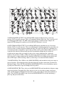
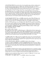
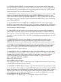
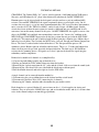
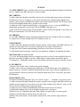
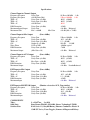
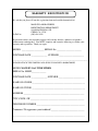
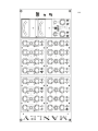
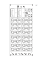
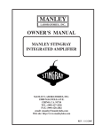
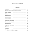
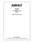
OWNER'S MANUAL
MANLEY
16 x 2
TUBE MIXER
MANLEY
LABORATORIES, INC.
MANLEY LABORATORIES, INC.
13880 MAGNOLIA AVE.
CHINO, CA. 91710
TEL: (909) 627-4256
FAX: (909) 628-2482
http://www.manleylabs.com
email: emanley @ manleylabs.com
email: service @ manleylabs.com
CONTENTS
SECTION
PAGE
INTRODUCTION
3
BACK PANEL & CONNECTING
4,5,6,7
FRONT PANEL
8,9
TECHNICAL DETAILS
10
TUBE BOARDS
11
OPTIONS
12
SPECIFICATIONS
13
ADJUSTMENTS
14
TROUBLESHOOTING
15,16
MAINS CONNECTIONS
17
WARRANTY
18
WARRANTY REGISTRATION
19
TEMPLATES FOR STORING SETTINGS
20,21,22
INTRODUCTION
THANK YOU!...
for choosing the Manley 16 x 2 TUBE MIXER. While there are plenty of choices in low budget mixers
and consoles in the $30K to $200K with a myriad of features, buttons, EQs, etc. there is very little available
that simply feature sonic quality and a minimum of knobs. This mixer is mainly intended for those who
use and love workstations and plug-ins but find the aspect of mixing digitally to be frustrating their efforts
to achieve the finished result they crave. Others, with huge expensive keyboard rigs have found that
inexpensive mixers are not up to the task or are the weak link in the chain. There are also engineers who
need to record live music with a portable system and also need the quality not generally associated with
semi-pro gear. The Mic Version and 8+8 Version are well suited for this.
This manual describes both the Mic Version, Line Version and 8+8 Version and any pictures will show
the 8+8 Version so that all 3 versions are explained. The channel electronics of both versions are almost
identical. The Mic Version adds a number of resistors on an eleven position Grayhill gold contact rotary
switch that set the gain of the first stage while the Line Version does not use these resistors and operates
at unity gain. The Mic Version also has switches for INSERT and Phantom Power not needed on the line
version plus a switch for Phase Reverse mostly useful on Mic inputs. The input stage is a high performance
low noise instrumentation amp that we use in Manley's custom mastering consoles.
The L&R summing amps are 100% tube and transformer circuits very similar to the make-up amps in the
Massive Passive. This provides the desired "warmth factor" and dynamic richness and headroom that
Manley is known for. Additional features include External and Tape Inputs, and a separate monitor path
with provision for two sets of speakers.
GENERAL NOTES
LOCATION & VENTILATION
The Mixer is designed to be mounted either in a rack or a table with a 8.75" x 17.25" rectangular hole. The
Manley 16 x 2 Mixer should be installed in a stable location with ample ventilation. It is recommended,
if this unit is rack mounted, that you allow enough clearance on the top of the unit such that a constant
flow of air can move through the ventilation holes.
You should also not mount the Massive Passive where there is likely to be strong magnetic fields such
as directly over or under power amplifiers or large power consuming devices. The other gear's fuse values
tend to give a hint of whether it draws major power and is likely to create a bigger magnetic field. Magnetic
fields might cause a hum in the mixer due to transformers and occasionally you may need to experiment
with placement in the rack to eliminate the hum. In most situations it should be quiet and trouble free.
WATER & MOISTURE
As with any electrical equipment, this equipment should not be used near water or moisture.
SERVICING
The user should not attempt to service this unit beyond that described in the owner's manual.
Refer all servicing to your dealer or Manley Laboratories. The factory technicians are available for
questions by phone (909) 627-4256 or by email at <[email protected]>. Fill in your warranty
card! Check the manual - Your question is probably anticipated and answered within these pages......
3
THE BACK PANELS
2
1 0
1
3
4
1) MAINS ON / OFF SWITCH. "0" indicates OFF, "1" indicates ON. This should be set to OFF or O before plugging in any cables.
2) VOLTAGE LABEL (ON SERIAL STICKER). Just check that it indicates the same voltage as is normal in your country. It should
be. If it says 120V and your country is 220V, then you should look inside the power supply and behind the Mains Switch is a "change-over
switch" which has the numbers 110 and 220. Use an appropriate sized flat blade screwdriver to set it for the correct voltage for your area.
3) IEC MAINS SOCKET. In the box your mixer came in, is the IEC MAINS CABLE that should be wired correctly for your AC power.
Connect the mating side here and the plug to your AC power at the wall. This is all pretty normal with most audio gear.
4) POWER CONNECTOR. The thick captive cable from the back of the mixer gets connected here. Rotate it to align it properly then
the ring screws clockwise about a half turn to lock into place. This cable carries all the various power supply voltages to the mixer. Power
should be OFF while connecting and disconnecting this big cable and should be OFF for about 5 minutes before disconnecting to allow
the the power supply to discharge. It carries 350 volts DC for the tubes which can potentially arc pins and shorten their life or if touched
by fingers give a nasty shock or burn but the current is low and non-lethal. The large pins carry 12 volts DC for tube filaments and for LEDs
and Relays. These are higher current lines. Multiple redundant pins are used for other supplies for reliability and lower resistance.
One pair of pins carry 48 volts DC used for Phantom Power which will be on even if the power switch on the front panel of the mixer is
off. It is also used for that same front panel power switch to turn on relays that turn on the other volts. In other words, there are two power
transformers. There is a little one for the 48 volts which draws almost no power, and a rather big one for most of the mixer. The little one
is used to remote control the big one and turn on the bulk of the power supply. It also means that the bulk of the power supply can't be turned
on unless the mixer is attached via the Power Connector . This certainly makes connecting it safer but always have power switches turned
off before connecting it and, again, let the supplies discharge for at least 5 minutes before disconnecting.
4
5
13
6
14
7
15
8
16
9
17
10
11
18
12
19
20
5) MIX BALANCED OUTPUT. Left and Right MIX outputs intended to feed a 2 track tape
machine, DAT or A to D converter. These are transformer balanced Pin 2 hot. This is the mix of all
16 channels plus EXT inputs. The MIX control is the final level control for these outputs. All
outputs MUTE during power up/down or if the MIX MUTE button is selected.
6) MIX UNBALANCED OUTPUT. Left and Right MIX outputs intended to feed a 2 track tape
machine, DAT or A to D converter. These are transformerless unbalanced tip hot. In general one can
use these to drive a balanced input or unbalanced input. The ring of the TRS jack is grounded via a
resistor that provides an impedance equal to the tip which ensures good common mode rejection. It
is possible that either the balanced and especially the unbalanced output may be capable of
overdriving the input of the receiving device due to the extreme headroom that a good tube
linedriver can provide (+37 dBu !). Either the balanced or unbalanced outputs can be used to chain
mixers for twice as many channels but the unbalanced TRS allows for simpler wiring into the next
mixers EXT inputs. SOLO chaining is done by connecting a wire from the SOLO terminals.
7) MONITOR XLRs. These XLRs are the MAIN MONITOR sends intended to feed power amps or
powered speakers. Wired unbalanced pin 2 hot but balanced Z to allow connections to balanced or
unbalanced inputs. These MUTE when MINI or MONITOR MUTE is selected and during a powerup and power down delay to prevent thumps into the speakers.
8) MINI MONITOR TRS. These jacks are the MINI MONITOR sends intended to feed power amps
or powered speakers. Essentially they allow one to use two sets of speakers or more convenient
cables. Wired unbalanced TIP hot but balanced Z to allow connections to balanced or unbalanced
inputs. These MUTE when MINI is not selected or MONITOR MUTE is selected and during a
power-up and power down delay.
5
9) PHANTOM POWER. This switch is for the 48 volts needed for most solid state condensor mics.
It is not generally needed for tube mics, dynamic mics, ribbon mics and in some cases may be
harmful to some old vintage ribbon mics. Each switch is for a bank of 4 channels (1-4, 5-8, 9-12, 1316) and is a LOCKING TOGGLE which needs to be pulled to switch. This is a safety feature to
prevent huge pops from hurting speakers and sensitive ears. Mic signals are usually 1/100th of a
volt and phantom is 48 volts so a sudden change from switching phantom on or off can make a
horrendous thump. This can also happen if one plugs in a mic or mic cable or patch when phantom is
on. Try to get in the habit of turning down the channel and/or muting the Mix and Monitor to prevent
surprises and blown speakers. Also keep in mind, that slightly flaky mic cables or patch points may
seem much worse with phantom on. Phantom power may still be on even if the front panel power
switch is off because it is also used to remote control the main supply relays.
10) MIC CHANNEL INPUTS. These are COMBI jacks that allow either XLR or TRS plugs to be
used. With XLRs the input impedance is 2400 ohms which is suitable for mics but may be low for
some line level gear, especially semi-pro and consumer gear. The symptom would usually be
premature clipping. If one uses a 1/4" TRS plugs, then the input impedance switches to 82K ohms
which is an easy load for almost all gear including guitars and basses but probably too high for many
mics. In other words use XLR plugs with mics and TRS with instruments and either with pro line
level sources and it automatically works. With semi pro -10 dBv gear and synths, you will usually
get best performance with TRS plugs and turning the MIC GAIN up 1 notch to "15 dB" of gain.
PIN 1 = SLEEVE = GROUND = SHIELD
PIN 2 = TIP = HOT = Positive
PIN 3 = RING = LOW = Negative
These inputs allow inputs as hot as +30 dBu balanced or +24 dBu unbalanced before clipping when
the MIC GAIN is set for "0 dB", which is about 6 dB better than most pro gear can send, so clipping
the mic inputs with line signals should be unusual. The LINE INPUT channels use this same 0 dB
configuration. The MIC INPUTS also allow for 60 dB of maximum gain with the MIC GAIN turned
up sufficient for most miking situations with another 10 dB with the MIX levels cranked.
11) INSERT JACKS. These TRS jacks allow the amplified mic signals to be sent and returned from
a compressor, EQ, gate, etc. A front panel switch (INS) is used to turn on a relay to use the return or
to bypass the rack processing and extra components in the signal path. This insert is post mic pre, but
before the MIX gain, MUTE and PAN.
T= TIP = SEND, R= RING = RETURN, S = SLEEVE = Shield = Chassis Ground.
All signals are unbalanced and follow a standard wiring format used in many other mixers. There is
no point in providing and INSERT for the unity gain LINE INPUTS because we can patch an EQ or
other device between the source and mixer and retain balancing and headroom and avoid unneeded
extra components in the path but because Mic Preamps provide needed gain there is a definite need
for INSERTS there.
12) CHANNEL OUTPUTS. Balanced outputs used to feed individual tracks on a multitrack recorder
or A to D converter. These outputs are after the MIX GAIN controls but are not muted by the MUTE
button. So by muting, you can eliminate these channels from the mix buss but still send to a
recorder. This way, you can use the Mic Pre, Phase Switch, Insert and Mix Gain (for fine level
control) on its way to a multi-track. These outputs are capable of +30 dBm drive levels once again
enough to pin the meters of most anything.
T= TIP = HOT = +, R = RING = Low = -, S = SLEEVE = Shield = Chassis Ground.
6
13) TAPE PLAYBACK INPUTS. Used for returning a 2 track tape machine or DAT back to the
mixer for monitoring, checking or just listening. Once one records a mix, it is always a good idea to
check playback. The 5 position monitor select switch on the front hast to be in the "TAPE" position
to hear the playback. These are balanced inputs, TIP hot.
14) EXT INPUTS. Used for chaining mixers for 32 channels if you have 2 mixers and the 1/4" MIX
outputs are fed from the other mixer into these jacks. On MIC VERSION mixers there is a gain
control on the front panel (EXT) and on LINE VERSION it is a unity gain input direct into the mix.
These inputs can be used as an effects return if not required for chaining mixers. These are balanced
jacks, TIP hot, RING neg.
15) AUX OUTPUT. Only on the LINE and 8+8 VERSIONS. This is the effect send or a mono
headphone send. Channels can feed this jack if their AUX control is turned up and the AUX knob in
the master section is also up. This is an unbalanced output on a balanced TRS jack and can be used
to feed balanced or unbalanced inputs.
16) SOLO LINK. If one has 2 mixers, they can simply connect a wire between these terminals to
link the SOLO system. This allows you to solo one channel and the other 31 channels mute. If the
16x2 is used as a "sidecar" for a large console, it might also be used to link to the solo system of the
larger desk. 12 volts = no solo, 0 volts = solo. This is a mini banana post and not the larger size used
on test gear.
17) GROUND POSTS. Generally, there should be a wire connecting these two posts. One is
CHASSIS GROUND which is also the third pin of the AC plug. The other post is AUDIO
GROUND which is the zero volt common of all the audio signals. Having these grounds accessible
is useful for solving hum problems and for installations with custom ground schemes. For reference,
all 1/4" TRS sleeves or shield points are taken to chassis ground, and all rings are taken to audio
ground via a 30 ohm resistor. The internal star ground reference is on the left tube board at the
summing transformers / power connector.
18) LINE INPUTS. These are COMBI jacks that allow either XLR or TRS plugs to be used. Unlike
the MIC INPUTS the input impedance is always 82K ohms which is an easy load for almost all gear
including guitars and basses. With semi pro -10 dBv gear and synths, if more gain is needed, a
resistor can be added on any channel to increase gain as required. See page XX for details.
PIN 1 = SLEEVE = GROUND = SHIELD
PIN 2 = TIP = HOT = Positive
PIN 3 = RING = LOW = Negative
These inputs allow inputs as hot as +30 dBu balanced or +24 dBu unbalanced before clipping which
is about 6 dB better than most pro gear can send.
19) CHANNEL OUTPUTS. Balanced outputs used to feed individual tracks on a multitrack recorder
or A to D converter. These outputs are after the MIX GAIN controls but are not muted by the MUTE
button. So by muting, you can eliminate these channels from the mix buss but still send to a recorder
with these jacks. This way, you can use the Mic Pre, Phase Switch, Insert and Mix Gain (for fine
level control) on its way to a multi-track. These outputs are capable of +30 dBm drive levels once
again enough to pin the meters of most anything.
T= TIP = HOT = +, R = RING = Low = -, S = SLEEVE = Shield = Chassis Ground.
7
1
2
3
4
5
6
THE FRONT PANEL
7
PAN
L
INS
L
R
35
30
25
40
45
INS
35
30
25
40
45
20
50
20
50
15
0
55
60
15
0
55
60
180
5
4
6
3
2
1
8
3
9
2
1
6
MIC
8
MIX
2
35
40
45
INS
L
R
35
30
25
40
45
INS
L
R
35
30
25
40
45
INS
L
R
35
30
25
40
45
20
50
20
50
20
50
20
50
15
0
55
60
15
0
55
60
15
0
55
60
15
0
55
60
5
4
6
2
8
3
9
2
6
1
10
MUTE
SOLO
5
4
180
7
3
1
MUTE
L
R
30
25
10
SOLO
MUTE
INS
180
7
9
1
10
SOLO
5
4
180
7
PAN
L
R
180
7
4
8
3
9
2
10
SOLO
4
3
5
6
1
MUTE
4
180
7
8
3
9
2
8
9
4
5
L
8
3
9
2
6
2
1
6
6
8
3
4
AUX
9
4
7
L
7
6
4
7
8
3
8
2
9
2
9
10
1
10
MIX
R
L
8
3
9
2
6
4
7
1
3
1
5
2
10
5
50
20
55
60
15
0
5
4
6
3
2
8
3
9
2
55
60
6
MUTE
7
8
16
9
1
10
SOLO
40
45
50
5
4
180
7
R
35
30
25
15
0
1
MUTE
INS
10
SOLO
8
7
x
MUTE
6
4
7
L
8
3
9
2
6
4
7
1
10
5
5
R
6
4
7
L
8
3
9
2
6
4
7
1
10
5
5
R
6
3
AUX
6
3
8
3
8
3
8
2
9
2
9
2
9
2
9
1
10
1
10
1
10
1
10
MIX
3
6
9
2
R
4
5
7
6
7
4
3
8
2
9
2
9
1
8
9
MUTE
SOLO
MUTE
10
SOLO
MUTE
11
SOLO
MUTE
12
SOLO
13
MUTE
SOLO
8
MUTE
14
SOLO
MUTE
15
SOLO
10
9
5
MON
6
7
8
2
9
1
10
8+8x2
MIC
LINE
4
MON
5
6
7
3
8
2
9
1
10
MON
MIXER
M
U
T
E
MIX
PB
EXT
10
3
MUTE
16
MIX
MONO
AUX
AUX
8
10
7
1
3
1
POWER
ON
6
2
9
10
5
5
3
8
4
7
4
6
1
10
5
4
7
8
L
8
7
1
3
R
6
2
10
5
5
4
7
9
4
7
L
8
6
1
10
5
5
R
MIX
SOLO
2
PAN
R
6
1
10
5
5
4
7
3
4
R
MIX
40
45
20
180
7
PAN
L
MIC
L
R
35
30
25
10
SOLO
MUTE
5
6
1
10
SOLO
5
INS
S
P
K
R
MINI
DIM
9 10 11 12 13 14 15 16 17 18
1) MIC GAIN. This knob sets the mic preamp gain from 0 dB to 60 dB in 5 db increments. With
highest gains, we advise a little caution. Suddenly a quiet mic or half working patch will decide to
work and ka-boom... and you may regret not checking why you had to turn it up that far.
2) 180. This micro toggle is used to reverse the polarity (phase) on the mic signal. It uses a relay
rather than one more IC and lights a LED to clearly indicate "phase reverse".
3) INSERT. This micro toggle is used for inserting a compressor, EQ, or gate after the mic pre and
before the Mix Gain pot. It also uses a relay to pick up the signal from the INSERT jack.
4) MIX GAIN. Sets the channel level to the CHANNEL OUTPUT jack and to the stereo mix buss.
This is just like a fader on a large console. Unity gain (zero) is at approximately 2:00 on the knob
and maximum gain is +10 dB with the knob fully clockwise.
5) SOLO. This button allows you to listen to this track only, by muting every other channel. Of
course you can solo any number of tracks and mute channels that are also soloed. GREEN leds =
SOLO, which also tends to also turn on many red MUTE leds.
6) MUTE. Simply removes that channel or track from the mix. The MUTE button has no effect on
the CHANNEL OUTPUT jacks so they are available for direct outputs to a multi-track without also
sending them to the mix. One can return the multi-track to any available channnels for mixing and
monitoring. RED leds = MUTE.
7) PAN. Allows you to place the track across the left and right mix and position it where you want.
This pan is 4.5 dB down in center like the old British desks. With the MIX GAIN fully clockwise,
and PAN fully clockwise, the signal will have 10 dB of gain in the right channel and nothing in the
left.
8
8) AUX. Only on LINE VERSION channels. A separate mono mix that can be used as an effects
send or headphone send. These are factory wired to be post fader and post cut but there are internal
jumpers right next to the aux pot that allow pre fade aux or even post fade, pre cut. Like the MIX
GAIN pots unity gain is approximately 2:00
9) AUX MASTER, EXT GAIN. On LINE VERSIONS this control is the final level control for the
AUX send. On MIC VERSIONS it is a stereo gain control for the EXT INPUTS into the stereo mix.
The typical setting would be fully clockwise.
10) MIX. This is the master gain for the stereo mix before it hits the tube stages. The typical setting
would be fully clockwise.
11) MIX MUTE. Simply mutes the MIX outputs for complete silence. It automatically mutes during
power up or down to prevent huge pops.
12) MONITOR MUTE. Simply mutes all 4 of the monitor outputs for complete silence. It also
automatically mutes during power up or down to prevent speaker damage.
13) POWER. This is a LOCKING TOGGLE - pull to switch. Upon power up, the left VU will light
and the MIX MUTE and MONITOR MUTE leds will light indicating mute while the tubes warm up
and the power supplies settle. About 20 seconds later, the right VU will light and the MUTES will
unmute (unless they are pushed in). At power-off there is instantaenous mute to protect speakers, etc.
The power switch is actually a remote control that turns on the main transformer for all the volts that
mixer uses. The "Phantom Power" transformer is "always-on" unless the power switch at the IEC
receptical is turned off and is used also for that remote control.
14) MONITOR SELECT. This is a 5 position rotary switch that allows several different console
signals to be sent to the speakers via the monitor outputs. This includes the main stereo mix, a mono
version of the mix for compatibility checks, TAPE for playback of the mix from a DAT or other 2
track machine, AUX to check the Aux mix and EXT just to verify that this input is fine.
15) MONITOR. The volume knob for the stereo speakers, via the monitor output jacks. The same
knob is used for both the Main Monitor and Mini's. If there is a level discrepancy between them,
then you may have to turn down one pair of power amps.
16) MINI. Switches between the Main Monitors and MINI Monitors.
17) DIM. Drops the level of either set of monitors by 15 dB. Useful for answering the phone.
18) VU METERS. The top VU is left, bottom is right. The bottom VU lights once the power-up
delay has happened. VU meters are almost always calibrated for pro levels which means that Zero
VU = +4dBm (1.228 volts RMS). VU meters generally agree with each other which is great for
analog tape and estimating percieved loudness but they will generally be in total disagreement with
the kind of peak meters used with digital recorders or A to D converters. Peak meters are not
generally standardized but should be the primary meters you use when recording digitally. You have
to watch the record machine or A to D converter to prevent "overs".
9
TECHNICAL DETAILS
CHANNELS: The Combi (XLR / 1/4") jack is wired to provide a 2400 ohm load for XLR sources
like mics, and 82K ohms for 1/4" plugs either balanced or unbalanced. On MIC VERSIONS
Phantom power can be injected with the back panel switches and uses a pair of traditional 6K8
resistors. Also on MIC VERSIONS, the signal is optionally phase reversed with a relay. On all
versions, the next stage is a very low noise instrumentation amp / DC servo. For those into numbers,
noise is rated at 1nV/÷ Hz, THD+N at .0009%, and it cleanly accepts +30 dBu signals. Similar
circuits have been used on the most expensive consoles, dedicated mic pres and high end A to D
converters, but not this many channels at this price. On MIC VERSIONS, this signal is sent to a line
driver, the INSERT jack and back into an impedance converter, the "insert relay" and then to the
MIX GAIN pot. With INSERT bypassed or on the line versions the mic pre feeds the MIX GAIN
pot directly. The output of the pot is buffered with 10 dB of gain plus a bipolar class AB line driver
and fed to several points. These include the MUTE relay, Aux pot, Pan pot and Channel Output Line
Driver. The latter is isolated with a balanced line driver. The Aux pot and Pan pots are 1K
conductive plastic Bournes pots for reliability and low noise. There is a .1" header and jumper that
allows the Aux pot to be pre-fade, post-fade and post-fade&cut. The final step is 2K2 build-out
resistors for the summing busses. All signals use at least 2 pins on the header for signal integrity,
redundancy and low impedance.
Removal of a module of 4 channels is accomplished by:
1) Unscrewing and sliding back the top perforated cover.
2) Pulling up and off the 4 IDC ribbon connectors from the headers.
3) Removing the 8 plastic nuts from the 1/4" jacks and the 8 black 4-40 screws from the combi jacks
4) Removing the 4 hex head 4-40 screws that hold the black engraved front panel.
5) Pull the module forward, and to the right to clear the XLR locks.
A single channel can be removed from the module by:
1) Disconnecting the wire or ribbon between the channel and the switch board.
2) Disconnecting the Buss Wire (48V) connecting the 4 channels.
3) Removing the 3 knobs, and nuts under that mount the pots and/or switch.
Each channel uses a pair of 30 ohm 1/2 watt resistors on the +/- 24 volt supplies for fusing and
isolation. They are next to the 2200uF filter caps, and are intended to smoke and fry if a serious short
exists in the channel and prevent much bigger problems.
10
THE TUBE BOARDS
The left tube board takes the mix busses through the 1K MIX GAIN pots, then a 7:1 step-up
transformer. The left signal is amplified by a 25db tube voltage amp/line driver and the right signal
is sent to the right tube board. The voltage amp is a paralleled (for low noise) 12AT7wa direct
coupled into a White Follower line driver which uses a 6044. It is AC coupled with a 30 uF
audiophile grade Multi-cap into the 1/4" Unbalanced Mix Output and a Manley 9811 transformer for
the Balanced XLR Mix Output. A tertiary winding on the 9811 is used for negative feedback
through a trim pot for gain adjustment (located near the top of the board between the tubes). This
circuit is virtually identical to the tube stages used in the Massive Passive and produces +37 dBu
levels ! This stage is quite similar to a Mic Pre with moderate gains.
The left board also distributes most of the power supply busses including the +/- 24 volt, 12 volt led/
relay supply and the 48 Volt phantom supply. There are balanced line receivers for the left EXT
input, and left TAPE input, plus the MONO combining circuit and AUX Line Driver. The AUX buss
amp is a low noise device with 15V regulators next to it. The AUX Gain pot is after the buss amp
and feeds the line driver. This pot can be replaced with a dual pot and jumpers changed to have it
control the EXT levels into the mix buss and monitor switch.
The right tube board has the same tube stage and balanced line recievers for EXT and TAPE, plus
circuitry involved in the monitor section. All monitored signals are sent to a Grayhill gold contact 5
position switch and the selected signals are sent to the VU meter board and the monitor pot. From
the pot, the signal is buffered with heavy duty line drivers and sent to relays for MUTE and Main /
Mini selection on its way to the Monitor jacks.
The right tube board also distributs the 350 volts and 12 volts used for the tube circuits.
The VU board contains the isolation amps for the VU meters and trims for VU calibration plus the
timer used for power-up delay (about 20 seconds). There is also termination for the front panel
power switch, VU illunination, Switch logic, etc.
Removing these boards is similar to removing a channel module. Removing the right tube board is
neccessary in order to remove the left board due to the physical size of some of the parts. Extra care
is required because capacitors can hold a charge long after power is disconnected and with tubes the
stored charge can be 350 volts. Let them discharge! Replacing a tube should not require removing
the boards, just the top cover.
Removal of the tube boards is accomplished by:
1) Unscrewing and sliding back the top & bottom perforated covers.
2) Pulling up and off the white AMP PSU connector and IDC ribbon connector at the bottom of
theleft tube board.
3) Removing the3 hex head 4-40 screws that hold the black engraved front panel.
4) Remove the 4 knobs and 4 nuts that mount the pots and rotary switch.
4) Pull the panel forward away from the two boards.
6) Removing the 8 plastic nuts from the 1/4" jacks and the 8 black 4-40 screws from the XLR jacks
7) Pull the right board forward and out. If a ribbon connector is removed, note its location and
orientation. The left board can now be pulled gently out.
11
OPTIONS
The LINE VERSION can be considered the basic root version and additional daughter boards and
parts are added for the MIC and special versions or mods.
MIC VERSION:
1) Adds a front panel daughter board that contains an 11 position gold contact rotary switch from
Grayhill and a series or resistors to set the gain of the input stage instrumentation amplifier.Also
contains 2 micro toggles and LEDs that controls relays on the channel boards. The AUX pot cannot
be fitted if thedaughter board and 11 position switch is fitted.
2) Adds parts to the channel board including: a relay for phase reverse, a relay for INSERT and
another dual op-amp and associated parts for the INSERT send and receive.
3) The AUX master gain pot on the left tube board is replaced with a dual pot that is then used as an
EXT gain control (there is no AUX on the Mic Version)
8+8 VERSION
Uses the MIC VERSION changes and daughterboards for the first 8 channels. The last 8 channels
are regular Line Versions. Intended for live recording in clubs etc.
BUSS VERSION:
1) Adds a front panel daughter board that contains contains 2 micro toggles with LEDs and relays to
routethe post pan signals to 2 stereo busses and from the Aux amp to 2 mono busses.
2) Adds parts to the channel board including: build-out resistors for the extra busses.
3) Adds another board containing 3 solid state buss amplifiers sending to the unbalanced outputs.
SPECIAL LINE: A Line/Mic hybrid
1) Uses the Mic daughterboard and extra channel parts to have a Line Version with Phase Reverse
and either switchable +12 dB of gain (for -10dBv inputs) or other simple function like Inserts.
2) Alternatively, -10 dB dBv switches can be placed where the Insert jack goes on the Mic Version.
L/C/R VERSION:
1) Replaces the Pan Pot with a 3 deck pot for partial surround.
2) Adds a 3 buss solid state summing amp which derives L/C/R which replaces the unbalanced
outputs and uses 1 extra hole. Sends the normal L/R to the tube stages which are modified for less
gain (transformers removed) and sent to the balanced outputs only. There is no master gain on the
L/C/R outputs.
BUSS VERSION 32x8;
We had not intended on doing this, but it was a sincere request ....... build me a 32x8 mixer, please.
1) Adds a front panel daughter board that contains contains 2 micro toggles and LEDs and relays to
routethe post pan signals to 3 stereo busses of 4 total. Some channels go to A,B or C, some to A, B
or D stereo busses. Bottom micro toggle flips phase.
2) Adds parts to the channel board including: build-out resistors for the extra busses.
3) Adds another ribbon cable to all the daughter boards for the extra busses
4) Replaces the 1/4" aluminum front panel with a double size panel and 1 new master panel
5) Replaces one back panel with one for the new busses etc.
6) Rather than 4 tube boards, 2 of the boards contain all the solid state buss amps and insert
functions.
12
Specifications
Channel Input to Channel Output
Frequency Response
Unity Gain
Frequency Response
+40 dB Gain (Mic)
THD + N
Unity Gain (+4 dBu)
THD + N
Unity Gain (+28 dBu)
THD + N
+40 dB Gain
DIM Distortion
Unity Gain (+4 dBu)
Maximum Input/Output
Unity Gain
Maximum Gain
Mic = +60 dB
Mix Gain
10 Hz to 200 kHz -1 db
5 Hz to 100 kHz -1 db
.002% (-90 dB)
.005% (-85 dB)
.001%
-85 dB
+28 dBu Balanced
+10 dB (Mic = 70 dB)
Channel Input to Mix Output
(Line +4dBu)
Frequency Response
Unity Gain
THD + N
Unity Gain (+0 dBu)
THD + N
Unity Gain (+14 dBu)
S/N
Output @ +33 dBu
Noise Floor
22 Hz to 20K
DIM Distortion
Unity Gain (+0 dBu)
Maximum Output
(Mix Gain +10)
5 Hz to 100 kHz -1 db
.05% (-65 dB)
1% (-40 dB)
109 dB
22-20K
-80 dBu typical
-74dB
+33 dBu Balanced
Channel Input to AUX Output
(Line +4dBu)
Frequency Response
Unity Gain
THD + N
Unity Gain (+4 dBu)
THD + N
Max Gain (+20 dB)
DIM Distortion
Unity Gain (+0 dBu)
Maximum Output
10 Hz to 50 kHz -3 db
.005% (-85 dB)
.005% (-85 dB)
-85 dB
+24 dBu PseudoBalanced
EXT Input to Mix Output
Frequency Response
THD + N
THD + N
DIM Distortion
Maximum Input
10 Hz to 80 kHz -3 db
.05% (-65 dB)
1% (-40 dB)
-85 dB
+24 dBu Balanced
(Line +4dBu)
Unity Gain
Unity Gain (+4 dBu)
Unity Gain (+14 dBu)
Unity Gain (+4 dBu)
EXT Input to MONITOR Output
(Monitor selected to AUX, Tape similar)
Frequency Response
Unity Gain
10 Hz to 100 kHz -3 db
THD + N
Unity Gain (+4 dBu)
.001% (-100 dB)
THD + N
Unity Gain (+20 dBu)
.01% (-80 dB)
DIM Distortion
Unity Gain (+0 dBu)
-95 dB
Maximum Intput
+24 dBu Balanced
COMPONENTS
Tubes
Solid State
Switches/Pots
2 x 12AT7wa, 2 x 6414
Burr Brown INA103, OPA2604, Linear Technology LT1010
EAO Series 19, Grayhill Rotary, Bournes Conductive Plastic 91
C&K GT Series, Tocos Toggles, Siemens & Magnecraft Relays
13
ADJUSTMENTS
MIX GAINS:
There is a single trimmer on each tube board to set the summing amp gain. It adjusts the amount of
negative feedback from a special tertiary winding on the output transformer back to the first tube
stage cathodes. These trims are located near the top of each tube board, between the tubes.
Adjustment can be done just by sliding back the top perforated cover once the two 4-40 screws that
hold the cover are removed (from the back panel).
1) Using the EXT inputs, feed a +4 dBv (1.228 volt RMS) 1kHz sine wave into the mixer. Turn the
MIX level to fully clockwise. Set the Monitor switch to MIX.
2) Using a known accurate VU meter, dBm meter, or multimeter set to AC volts, adjust the trimmers
for an output of, 0 VU or +4 dBm or 1.228 (1.23) volts between the tip and ring of the Unbalanced
MIX OUTPUTs (or XLR Pin 2 and Pin 3).
3) Alternatively, use the mixer's VU meters but this may not guarantee absolute accuracy because
they also have trims that may be slightly out of calibration. Using a known reference, like a good
multimeter, will show you if the VU meters also need trimming. Generally, the tube stage is
expected to drift slightly especially if tubes are replaced but the VU meters should stay much more
stable over time.
4) Switch channels and check and/or trim the other side too.
VU METERS:
There are 2 trimmers on the VU meter board to set the summing amp gain. It allows a few dB of trim
range for calibration purposes. Adjustment can be done just by sliding back the top perforated cover
once the two 4-40 screws that hold the cover are removed (from the back panel).
1) If you have performed the above MIX GAIN calibration and the VU meters are not at zero, adjust
each of the VU trims (one for left, one for right).
General Test:
1) If this is a MIC VERSION, set all channels to "0" gain on the rotary switches. Otherwise, set the
Mix Gain pot to fully clockwise and the Pan to Left. Feed a +4 dbm 1K tone into any channel and
the left VU meter will pin hard & Mix Output should show a level of +14 dBm or 12.28 volts RMS.
2) Reduce the master MIX GAIN pot until the VU meter is at "0" which should be around 2:00.
3) Pan Right and the right VU should show near "0" VU. Don't panic if it is a bit out, there is usually
a bit of variation in pots.
14
TROUBLE-SHOOTING
There are a number of possible symptoms of something not quite right, some may be interfacing, others we will touch
on as well. If you suspect a problem the following paragraphs should help.
NO POWER, NO INDICATORS, NADA - Probably something to do with AC power. Is it plugged in? Check the fuseon
the back panel. A blown fuse often looks blackened inside or the little wire inside looks broken or it's resistance measures
higher than 2 ohms. A very blackened fuse is a big hint that a short occured. Try replacing the fuse with a good one of the
same value and size. If it blows too, then prepare to send the unit back to the dealer or factory for repair. The fuse is a protection
device and it should blow if there is a problem. If the unit works with a new fuse, fine, it works. Sometimes fuses just blow
for unknown reasons.
LIGHTS BUT NO SOUND - First try plugging the in and out cables into each other or some other piece of gear to verify
that your wires are OK. If not fix them or replace them. Assuming that cables passed sound - it probably is still a wiring thing.
The output XLRs are transformer balanced which require both PIN 2 and PIN 3 to be connected somewhere. When driving
an unbalanced input ( inserts on some consoles) PIN 3 needs to be grounded or connected to PIN 1. Same with the unbalanced
1/4 inch jacks - if driving a balanced input you can't ignore the negative side. It needs to be connected to the sleeve of the phone
plug. Another way to do basically the same thing is join PIN 1 and PIN 3 on the XLR male at the destination. Easiest way
- Use the balanced with balanced, unbalanced with unbalanced. That is why the options are there.
LEVELS SEEM TO BE WRONG, NO BOTTOM - Several possible scenarios. Manley uses the professional standard of
+4 dBm = Zero VU = 1.23 volts AC RMS. A lot of semi-pro gear uses the hi-fi reference of -10 dBm = Zero VU. This is a
14 dB difference that will certainly look goofy and may tend to distort. Often there are switches on the semi-pro gear to choose
the pro reference level. If the loss looks close to 6 dB and it sounds thin then one half of the signal is lost. The cause is probably
wiring again. One of the two signal carrying wires (the third is ground / shield on pin 1) is not happening. Check the cables
carefully because occasionally a cable gets modified to work with a certain unit and it seems to work but its wrong in other
situations. If only one side of the Mixer exhibits this problem, it may be a problem in the Mixer. See the next item.
ONE SIDE WORKS FINE BUT THE OTHER SIDE IS DEAD - Let's assume this is not wiring. We are pretty sure it is
the Mixer. If it were solid state you would generally send it back for repair. Being a tube unit, you can probably find the problem
and fix it yourself in a few minutes. Not too many years ago, even your parents could "fix" their own stuff by taking a bag
of tubes down to the corner and checking the tubes on a tube tester - but these testers are hard to find today. A visual inspection
can usually spot a bad tube just as well. Be careful - there are some high voltages inside the chassis and tubes can get pretty
warm, but if you can replace a light bulb you should be able to cruise through this. Before you remove a tube, just take a look
at them powered up. They should glow a bit and they should be warm. If one is not, you have already found the problem. The
tube's filament (heater) is burnt out or broken like a dead light bulb. The other big visual symptom is a tube that has turned
milky white - that indicates air has gotten into the tube or we've joked "the vacuum leaked out". Either way replace the tube.
Manley can ship you a tested one for a reasonable price. Before you pull a tube, pull the power out, let the unit sit and cool
and discharge for a minute or two, then swap the new tube in, then power, then check. Gentle with those tubes, don't bend
the pins by trying to insert the tube not quite right. A little rocking of them as you pull them out or put them in helps. The two
taller tubes are the same so you can swap them. If the problem follows the tube you found the problem - a bad tube. No
soldering, no meters, one screwdriver - easy.
HUM - Once again - several possibilities - several cures. Most likely it is a ground loop. Ideally each piece of gear should
have one ground connection and only one. However, the short list of grounds include the AC mains plug, the chassis bolted
to a rack with other gear, each input and each output. The two most common procedures are: try a 3 pin to 2 pin AC adapter
(about a dollar at the hardware store).This while legal in many countries can be dangerous- We went one better; Method two
- On the back panel loosen the GROUND TERMINALS and slide the small metal ground strap to one side. This is way better
than "method one" because it is safer and removes another possible source - the chassis grounding via the rack. Method three
- cutting the shield on oneend of each cable. This is done by some studios at every female XLR to "break" all ground loops.
All the other gear in the rack is "dumping" ground noise onto the ground. Try removing the EQ from the rack so that it is not
touching any metal. You just may have cured a non-loop hum. Some gear radiates a magnetic field and some gear (especially
if it has audio transformers or inductors) might receive that hum. A little distance was all it took. A good way to find one piece
of gear that may be causing hum is with the SOLO buttons. Generally with mixers, ground loops are the big hum cause.
Sometimes the best way is to unplug everything except one pair of monitors. It should be pretty quiet. Now start plugging
in each cable one-at-a-time, frequently re-checking with those individual channel volumes at first down then up. Keep
listening andwatching for a sudden increase. You may have to play with gains or grounds.
15
IT MAKES NOISES WHEN THE FRONT PANEL IS TAPPED - An easy one. Some tubes become microphonic over
time. That means they start acting like a bad microphone. Vibration has caused the supports for the little parts in the tube to
loosen and now the tube is sensitive to vibration. Easy - Replace the tube. Which one? The one that makes the most noise when
you tap it. Usually this will be one of the smaller (gain stage) tubes closest to the front. The Mixer will have to be on, connected
and speakers up but not too loud for the sake of your speakers.
IT GOT HISSY - Also easy. This is again a common tube symptom. You could swap tubes to find the bad boy, but an educated
guess is OK too. Generally the first tube in the path is the one with the most gain and dealing with the softest signals. The
usual suspect is the shorter tubes - the 12AT7wa voltage amplifiers. You may find that you need to choose the quietest tube
out of several of that type - like we do at the factory.
DISTORTION - This might be a tube. Swapping is a good way to find out. It may be a wiring thing or mismatch as well.
Wiring problems usually accompany the distortion with a major loss of signal. Mismatches are a bit tougher. The Mixer has
a high input impedance and low output impedance that can drive 600 ohm inputs of vintage "style" gear. Best place to start
is check your settings and meters. It may not be your first guess.
GETTING DISTORTION WHEN WE BOOST A LOT. No doubt. The Mixer by itself should have enough headroom
so that most settings won't cause clipping in it, however, it can push out about +33dBv, 7 to 13 dB more than most gear can
accept without clipping. You're gonna have to turn something down, whether it is the signal feeding the Mixer, the mixers
gain controls or the input levels of the next piece. That last option may not help if there is any op-amps before its own volume
control and unfortunately that is pretty common.
DC OR SOMETHING AT THE OUTPUT THAT IS INAUDIBLE - The 1/4" unbalanced outputs have a frequency
response that goes way down to below 1 Hz. A little very low frequency noise may be seen as speaker movement when
monitors are pushed to extreme levels. The XLRs do not exhibit this because the transformers filter below 8 Hz. Also the
unbalanced outputs do not like long cheap high capacitance cable. Occasionally a very high frequency oscillation (200 kHz
to 400 kHz) may occur in these conditions. Once again use the XLR outputs. Problem solved.
THE GAIN SEEMS OUT OF CALIBRATION - Wait a bit and see if it just needs to warm up. There are only two trimmers
inside for adjusting the gain of the two channels. The easy to check is put in a 0VU signal into the EXT inputs and the mix
should show 0VU too. Unity for each channel is in the middle of "7" with pan to one side, master at full.
Once in a while we get a call from a client with a "digital studio" with confusion about levels. They usually start out by using
the digital oscillator from their workstation and finding pegged VU meters the first place they look and they know it can't be
the workstation. Even a -6 level from their system pegs the meters. Some of you know already what 's going on. That -6 level
is referenced to "digital full scale" and the computer might have 18 or 18.5 or 20 dB of headroom built in. That -6 level on
the oscillator is actually a real world analog +12 or +14 and those VU meters don't really go much further than +3. There are
a few standards and plenty of exceptions. One standard is that normal (non-broadcast) VU meters are calibrated for 0VU =
+4 dBm =1.228 volts into 600 ohms (broadcast is sometimes +8dBm). Another standard is that CDs have a zero analog
reference that is -14 dB from digital full scale or maximum. This allows sufficient peak headroom for mixed material but
would be a bad standard for individual tracks because they would likely distort frequently. This is why digital workstations
use higher references like 18 and 20 - to allow for peaks on individual sounds. It may be too much in some cases and too little
in others. Add two other sources of confusion. Peak meters and VU meters will almost never agree - they are not supposed
to. A peak meter is intended to show the maximum level that can be recorded to a given medium. VU meters were designed
to show how loud we will likely hear a sound and help set record levels to analog tape. By help, we mean that they can be
only used as a guide combined with experience. They are kinda slow. Bright percussion may want to be recorded at - 10 on
a VU for analog tape to be clean but a digital recording using a good peak meter should make the meter read as high as possible
without an "over". Here is the second confusion: There aren't many good peak meters. Almost all DATs have strange peak
meters that do not agree with another company's DAT. One cannot trust them to truly indicate peaks or overs. Outboard digital
peak meters (with switchable peak hold) that indicate overs as 3 or 4 consecutive samples at either Full Scale Digital (FSD)
are the best. They won't agree with VU meters or Average meters or BBC Peak Programme (PPM) meters either. Each is a
different animal for different uses. When in doubt, use the recorder's meters when recording - they "should" be set up and
proper for that medium. Also important - if your DAC has gain trims, and these trims are "out" it can cause distortion,
confusion, and a variety of mis-matches. If you don't have calibration tapes or sources - get them, and if you do have them
- learn how to use them, and definately use them. Don't guess, especially if you suspect a significant problem. This is not the
type of thing "phone support" is usually good at finding. We have seen guys spend thousands on new gear only to find out
a little screwdriver trim would have solved their problems.
16
MAINS CONNECTIONS
Your 16 x 2 MIxer has been factory set to the correct mains voltage for your country. The
voltage setting is marked on the serial badge, located on the rear panel. Check that this
complies with your local supply.
Export units for certain markets have a moulded mains plug fitted to comply with local requirements. If your unit does not have a plug fitted the coloured wires should be connected to
the appropriate plug terminals in accordance with the following code.
GREEN/YELLOW
BLUE
BROWN
EARTH
NEUTRAL
LIVE
As the colours of the wires in the mains lead may not correspond with the coloured marking
identifying the terminals in your plug proceed as follows;
The wire which is coloured GREEN/YELLOW must be connected to the terminal in the plug
which is marked by the letter E or by the safety earth symbol or coloured GREEN or GREEN
and YELLOW.
The wire which is coloured BLUE must be connected to the terminal in the plug which is
marked by the letter N or coloured BLACK.
The wire which is coloured BROWN must be connected to the terminal in the plug which is
marked by the letter L or coloured RED.
DO NOT CONNECT/SWITCH ON THE MAINS SUPPLY UNTIL ALL OTHER
CONNECTIONS HAVE BEEN MADE.
Note: This unit has been factory wired for your country. If you plan to take the unit to
countries with a different mains voltage you will need to send the Limiter to Manley Labs
for the correct power transformer - or use AC voltage converters. See page 17 to convert
this unit for a different mains voltage.
17
WARRANTY
All Manley Laboratories
defects in materials and
purchase to the original
warranty is available to
ownership within 30 days
equipment is covered by a limited warranty against
workmanship for a period of 90 days from date of
purchaser only. A further optional limited 5 year
the original purchaser upon proper registration of
of date of first purchase.
Proper registration is made by filling out and returning to the factory the
warranty card attached to this general warranty statement, along with a copy of
the original sales receipt as proof of the original date of purchase. Only 1 card
is issued with each unit.
If the warranty registration card has already been removed then this is not a new
unit, and is therefore not warranted by the factory. If you believe this to be a
new unit then please contact the factory with the details of purchase.
This warranty is provided by the dealer where the unit was purchased, and by
Manley Laboratories, Inc.
Under the terms of the warranty defective parts will
be repaired or replaced without charge, excepting the cost of tubes. No warranty
is offered on tubes, unless:
1. a Manley Laboratories preamplifier is used with a Manley Laboratories
amplifier, and
2. the warranty registration card is filled out.
In such a case a 6 month warranty on tubes is available with the correct
recording of the serial number of the preamplifier on your warranty registration
card.
If a Manley Laboratories product fails to meet the above warranty, then the
purchaser's sole remedy shall be to return the product to Manley Laboratories,
where the defect will be repaired without charge for parts and labour. The
product will then be returned via prepaid, insured freight, method and carrier to
be determined solely by Manley Laboratories. All returns to the factory must be
in the original packing, (new packing will be supplied for no charge if needed),
accompanied by a written description of the defect, and must be shipped to Manley
Laboratories via insured freight at the customer's own expense. Charges for
unauthorized service and transportation costs are not reimbursable under this
warranty, and all warrantees, express or implied, become null and void where the
product has been damaged by misuse, accident, neglect, modification, tampering or
unauthorized alteration by anyone other than Manley Laboratories.
The warrantor assumes no liability for property damage or any other incidental
or consequental damage whatsoever which may result from failure of this product.
Any and all warrantees of merchantability and fitness implied by law are limited
to the duration of the expressed warranty. All warrantees apply only to Manley
Laboratories products purchased and used in the USA.
Some states do not allow limitations on how long an implied warranty lasts, so
the above limitations may not apply to you. Some states do not allow the
exclusion or limitation of incidental or consequential damges, so the above
exclusion may not apply to you.
This warranty gives you specific legal rights and you may also have other rights
which vary from state to state.
WARRANTY REGISTRATION
We ask that you please fill out this registration form and send the bottom half to:
Or FAX to
MANLEY LABORATORIES
REGISTRATION DEPARTMENT
13880 MAGNOLIA AVE.
CHINO CA, 91710
(909) 628-2482
Registration entitles you to product support, full warranty benefits, and notice of product
enhancements and upgrades. You MUST complete and return the following to validate your
warranty and registration. Thank you again.
MODEL ____________________ SERIAL No. ______________________
PURCHASE DATE ______________ SUPPLIER ______________________
-----------------------------------------------------------------------------------------------------PLEASE DETACH THIS PORTION AND SEND TO MANLEY LABORATORIES
MODEL MANLEY 16x2 TUBE MIXER
SERIAL No. MSMP_____________
PURCHASE DATE ______________ SUPPLIER _______________________
NAME OF OWNER _______________________________________________
NAME OF STUDIO _______________________________________________
ADDRESS ______________________________________________________
CITY, STATE, ZIP ________________________________________________
TELEPHONE NUMBER ___________________________________________
Comments? We appreciate your feedback!______________________________
________________________________________________________________
180
INS
5
6
SOLO
1
9
MUTE
10
7
9
10
2
6
8
4
5
3
1
7
9
6
8
4
R
MUTE
2
5
1
3
L
SOLO
10
9
2
1
8
7
3
4
180
5
2
7
SOLO
MUTE
10
10
9
8
9
10
6
7
2
1
5
6
8
1
4
R
MUTE
3
4
2
3
L
SOLO
10
9
7
55
60
2
6
40
45
50
8
1
5
35
R
3
4
15
0
55
60
15
0
30
25
20
40
45
INS
L
50
35
R
20
30
25
L
MIX
AUX
PAN
MIX
180
MIC
INS
PAN
1
4
7
9
8
SOLO
MUTE
10
10
7
9
8
9
11
6
6
R
MUTE
10
7
55
60
2
1
5
5
3
6
40
45
50
8
1
4
5
35
R
3
4
2
3
L
SOLO
2
3
15
0
20
30
25
L
180
INS
1
4
1
4
1
4
SOLO
2
3
2
3
L
SOLO
2
3
15
0
20
30
25
L
4
40
45
10
7
7
9
8
10
10
7
MUTE
6
6
R
9
8
9
8
55
60
50
MUTE
6
12
5
5
5
35
R
180
INS
1
4
1
4
1
4
SOLO
2
3
2
3
L
SOLO
2
3
15
0
20
30
25
L
5
40
45
10
7
7
10
10
9
8
MUTE
6
7
R
9
8
9
8
55
60
50
MUTE
6
6
13
5
5
5
35
R
180
INS
1
4
1
4
1
4
SOLO
2
3
2
3
L
SOLO
2
3
15
0
20
30
25
L
6
6
6
40
45
10
7
9
8
MUTE
10
10
7
R
9
8
9
8
55
60
50
7
MUTE
6
14
5
5
5
35
R
MIX
AUX
PAN
MIX
180
MIC
INS
PAN
1
4
1
4
1
4
SOLO
2
3
2
3
L
SOLO
2
3
15
0
20
30
25
L
7
40
45
10
7
9
8
10
10
7
MUTE
6
6
R
9
8
9
8
55
60
50
7
R
MUTE
6
15
5
5
5
35
180
INS
1
4
1
4
1
4
SOLO
2
3
2
3
L
SOLO
2
3
15
0
20
30
25
L
8
40
45
10
8
7
9
10
10
7
MUTE
6
6
R
9
8
9
8
55
60
50
7
R
MUTE
6
16
5
5
5
35
1
4
MIX
2
3
2
3
1
4
M
U
T
E
MIX
5
8
7
9
10
10
7
MON
6
6
AUX
5
9
8
MIXER
LINE
MIC
8+8x2
POWER
ON
1
4
MINI
2
3
MONO
AUX
S
P
K
R
MON
5
MON
MIX
6
DIM
10
7
9
8
PB
EXT
2
x
16
8+8
1
SOLO
1
9
MUTE
10
7
9
10
2
6
8
4
5
3
1
7
9
6
2
5
8
4
R
MUTE
3
L
SOLO
10
7
9
1
6
2
5
8
4
10
7
3
1
6
8
5
9
4
2
R
3
L
5
2
8
7
9
7
SOLO
MUTE
10
10
9
8
9
10
6
7
2
1
5
6
8
1
4
R
MUTE
3
4
2
3
L
SOLO
10
10
7
9
6
6
2
1
5
5
8
1
4
R
3
4
2
3
L
MIX
AUX
PAN
MIX
AUX
PAN
1
4
1
4
7
6
SOLO
MUTE
10
7
9
8
9
8
9
10
7
R
MUTE
6
11
8
9
10
10
7
2
1
5
5
3
6
6
8
1
4
5
5
R
3
4
2
3
L
SOLO
2
3
2
3
L
1
4
1
4
1
4
1
4
SOLO
2
3
2
3
L
SOLO
2
3
2
3
L
4
8
7
9
10
10
7
7
9
8
10
10
7
MUTE
6
6
R
MUTE
6
6
12
5
5
5
5
R
9
8
9
8
1
4
1
4
1
4
1
4
SOLO
2
3
2
3
L
SOLO
2
3
2
3
L
5
8
7
9
10
10
7
7
9
8
10
10
7
MUTE
6
6
R
MUTE
6
6
13
5
5
5
5
R
9
8
9
8
1
4
1
4
1
4
1
4
SOLO
2
3
2
3
L
SOLO
2
3
2
3
L
6
8
7
9
10
10
7
6
6
7
9
8
MUTE
10
10
7
R
MUTE
6
6
14
5
5
5
5
R
9
8
9
8
MIX
AUX
PAN
MIX
AUX
PAN
1
4
1
4
1
4
1
4
SOLO
2
3
2
3
L
SOLO
2
3
2
3
L
7
8
7
9
10
10
7
7
9
8
10
10
7
MUTE
6
6
R
MUTE
6
6
15
5
5
5
5
R
9
8
9
8
1
4
1
4
1
4
1
4
SOLO
2
3
2
3
L
SOLO
2
3
2
3
L
8
8
7
9
10
10
7
7
9
8
10
10
7
MUTE
6
6
R
MUTE
6
6
16
5
5
5
5
R
8
9
8
9
1
4
MIX
2
3
2
3
1
4
M
U
T
E
MIX
5
8
7
9
10
10
7
MON
6
6
AUX
5
9
8
MIXER
LINE
POWER
ON
1
4
MINI
2
3
MONO
AUX
S
P
K
R
MON
5
MON
MIX
6
DIM
10
7
9
8
PB
EXT
2
x
16
LINE
180
INS
180
INS
5
5
SOLO
MUTE
10
9
1
2
7
8
4
3
9
6
180
5
2
SOLO
MUTE
9
10
7
55
60
2
10
6
40
45
50
8
1
35
R
MUTE
10
3
4
15
0
55
60
15
0
30
25
20
40
45
INS
L
SOLO
1
9
7
2
6
55
60
50
40
45
8
4
5
35
R
3
50
35
R
MUTE
10
180
20
30
25
L
SOLO
1
9
2
7
8
4
3
1
6
15
0
55
60
30
25
15
0
INS
20
40
45
L
50
35
R
20
30
25
L
MIX
180
MIC
INS
PAN
MIX
180
MIC
INS
PAN
1
4
1
4
SOLO
2
3
15
0
20
30
25
L
SOLO
2
3
15
0
20
30
25
L
35
3
10
7
40
45
10
7
9
8
55
60
50
MUTE
6
R
9
8
55
60
50
40
45
MUTE
6
11
5
5
35
R
180
INS
180
INS
1
4
1
4
SOLO
2
3
15
0
20
30
25
L
SOLO
2
3
15
0
20
30
25
L
35
4
10
7
40
45
10
7
9
8
55
60
50
MUTE
6
R
9
8
55
60
50
40
45
MUTE
6
12
5
5
35
R
180
INS
180
INS
1
4
1
4
SOLO
2
3
15
0
20
30
25
L
SOLO
2
3
15
0
20
30
25
L
35
5
13
5
5
35
10
7
40
45
10
7
9
8
55
60
50
MUTE
6
R
9
8
55
60
50
40
45
MUTE
6
R
180
INS
180
INS
1
4
1
4
SOLO
2
3
15
0
20
30
25
L
SOLO
2
3
15
0
20
30
25
L
35
6
6
MUTE
10
9
8
55
60
50
7
R
40
45
10
9
8
55
60
50
40
45
7
MUTE
6
14
5
5
35
R
MIX
180
MIC
INS
PAN
MIX
180
MIC
INS
PAN
1
4
1
4
SOLO
2
3
15
0
20
30
25
L
SOLO
2
3
15
0
20
30
25
L
35
7
10
40
45
10
7
9
8
55
60
50
MUTE
6
R
9
8
55
60
50
40
45
7
R
MUTE
6
15
5
5
35
180
INS
180
INS
1
4
1
4
SOLO
2
3
15
0
20
30
25
L
SOLO
2
3
15
0
20
30
25
L
35
8
40
45
10
40
45
10
7
9
8
55
60
50
MUTE
6
R
9
8
55
60
50
7
R
MUTE
6
16
5
5
35
1
4
MIX
2
3
M
U
T
E
MIX
5
6
MON
10
7
8
10
7
9
EXT
6
2
1
5
3
4
9
8
MIXER
MIC
POWER
ON
1
4
MINI
2
3
MONO
AUX
S
P
K
R
MON
5
MON
MIX
6
DIM
10
7
9
8
PB
EXT
2
x
16
MIC