1
®
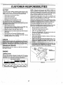
MODEL NUMBER 917=256522
t
OWNER'S MANUAL
o Assembly
Operation
• Customer Responsibilities
• Service and Adjustments
• Repair Parts
CAUTION:
,
Read and follow
FOR CONSUMER
IIIIIIIIIIII
IIIIIII
IIIIIIII
all safety
ASSISTANCE
rules and instructions
before operating
HOT LINE, CALL THIS TOLL FREE NUMBER:
this equipment.
1-800-659-5917
SAFETY RULES
Safe Operation Practices for Ride-On Mowers
IMPORTANT:
THIS CUTTING MACHINE IS CAPABLE OF AMPUTATING HANDS AND FEET AND THROWING OBJECTS.
FAILURE TO OBSERVE THE FOLLOWING SAFETY INSTRUCTIONS COULD RESULT IN SERIOUS iNJURY OR DEATH.
i,
.
°
°
°
°
°
•
•
°
•
o
•
°
•
°
il.
GENERAL OPERATION
Read, understand, and follow all instructionsin the manual
and on the machine before starting.
Only allow responsible adults, who are familiar with the
instructions, to operate the machine.
Clear the area of objects such as rocks, toys, wire, etc.,
which could be picked up and thrown by the blade.
Be sure the area is clear of other people before mowing, Stop
machine if anyone enters the area
Never carry passengers.
Do not mew in reverse unless absolutely necessary. Always
look down and behind before and while backing.,
Be aware of the mower discharge direction and do not point
it at anyone, Do not operate the mower without either the
entire grass catcher or the guard in place.
Slow down before tuming_
Never leave a running machine unattended. Always turn off
blades, set parking brake, stop engine, and remove keys
before dismounting_
Tum off blades when not mowing
Stop engine before removing grass catcher or unclogging
chute..
Mow only in daylight or good artificial lighL
Do not operate the machine while under the influence of
alcohol or drugs.
Watch for traffic when operating near or crossing roadways.
Use extra care when loading or' unloading the machine into
a trailer or truck.
i11, CHILDREN
Tragic accidents can occur if the operator is not alert to the
presence of children_ Children are often attracted to the
machine and the mowing activity.
Never assume that
children wilt remain where you last saw them.
°
Keep children out of the mowing area and under the watchful
care of another responsible aduIL
°
Be alert and turn machine off if children enter the area.
°
Before and when backing, look behind and down for small
children_
•
Never carry children. They may fail off and be seriously
injured or-interfere with safe machine operation_
,,
Never' allow children to operate the machine.
•
Use extra care when approaching blind corners, shrubs,
trees, or other objects that may obscure vision.
IV. SERVICE
°
Use extra care in handlinggasoline andother fuels_They are
flammable and vapors are explosive
Use only an approved container
Never remove gas cap or add fuel with the engine
running Allow engine to cool before refueling Do not
smoke,
Never refuel the machine indoors
Never store the machine or fuel container inside where
there is an open flame, such as a water heater,
Never run a machine inside a closed area.
Keep nuts and bolts, especially blade attachment bolts, tight
and keep equipment in good condition.
Never tamper with safety devices. Check their proper
operation regularly.
Keep machine free of grass, leaves, or other debris build-up_
Clean oil or fuel spillage. Allow machine to cool before
storing.
Stop and inspect the equipment if you strike an obiect,
Repair, if necessary, before restarting°
Never make adjustments or repairs with the engine running
Grass catcher componentsare subject to wear, damage, and
deterioration, which could expose moving parts or allow
objects to be thrown. Frequently check components and
replace with manufacturer's recommended parts, when necessary.
Mower blades are sharp and can cut Wrap the bEade(s) or
wear gloves, and use extra caution when servicing them.
Check brake operation frequently Adjust and service as
required.
=
°
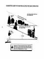
SLOPE OPERATION
Slopes are a major-factor
related to loss-of-control
and
tipover accidents, which can result in severe injury or death_
All slopes require extra caution, If you cannot back up the
slope or if you feel uneasy on it, do not mow it.
DO:
.
Mow up and down slopes, not across.
.
Remove obstacles such as rocks, tree limbs, etc.
=
Watch for holes, ruts, or bumps. Uneven terrain could
overturn the machine_ Taft grass can hide obstacles.
,,
Use slow speed, Choose a low gear so that you wilt not have
to stop or shift while on the slope°
•
Follow the manufacturer's recommendations for wheel
weights or counterweights to improve stability.,
°
Use extra care with grass catchers or other attachments.
These can change the stability of the machine..
.
Keep all movement on the slopes slowand gradual Do not
make sudden changes in speed or direction,
•
Avoid starting or stopping on a slope° If tires lose traction,
disengage the blades and proceed slowly straight down the
slope.
DO NOT:
•
Donot turn on slopes unless necessary, and then, turn slowly
and gradually downhill, if possible,
°
Do notmow near drop-offs, ditches, or embankments. The
mower could suddenly turn over if a wheel is over the edge
of a cliff or ditch, or if an edge caves in,
°
Do not mow on wet grass. Reduced traction could cause
sliding.
°
Do not try to stabilize the machine by putting your foot onthe
ground
•
Do not use grass catcher on steep slopes.
°
°
•
°
•
•
•
portant safety precautions.
It means
CAUTION!H BECOMEALERT!!!
YOUR
Look
for
this
symbol
to
point
out imSAFETY IS INVOLVED.
_
•-
tl ill
..............
it
,
:
CAUTION: Aiways'"d'isconnect spark plug
' '
spark
PlUg
in order
to prevent
accidental
wire and
place
wire where
it cannot
contact
starting when settlng up, transporting,
adjusting or making repairs.
& WARNING
The engine exhaust from this product contains cfiemicals known to the State of California to cause cancer,
reproductive harm.
..........................
,,
,,,,,
birth defects,
or other
/'
_
':",
_:-'_"'_"_;'_
','*
,7:'"
;'_;
""_'7-
'
> _ '_:_","
cO GI AT
LAT
'
.
_
P
, ....
g
IONS
on your
urch'_.se of a; Seai's
Tractor, ;it has been designed, engineered and manufactured ;to gi;_e _,ou the best possible dependability
and
performance.
:
,.
Should you experience
any problem you cannot easily
remedy, please contact your nearest Sears Authodzed
,Service Center/Department,,
We have competent, welltrained technicians and the proper tools to service or repair
thi s tractor,
=lease read and retain this manual, The instructions will
"enable you to as,_emble and maintain your tractor properly.
_ ,Always observe the "SAFETY RULES".
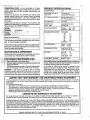
HORSEPOWER:
15,5
.
GAS(_LJNE CAPACITY
AND TYPE:
1o25 QUARTS
UNLEADED REGULAR
OIL TYPE (API-SFISG):
SAE 30 (above 32°F)
SAE 5W-30 (below 32°F)
OIL CAPACITY:
30 PINTS
SPARK PLUG:
(GAP: ,030"),
CHAMPION RJ19LM
STD361458
:
VALVE CLEARANCE:
INTAKE: ,
:_ ': ..... .iEXHAUST;
,005" ._°007"
.009 I'.,o011"
_GROONDsP'EED '(MPHii ;;_._:FORW,_t_I_:
,I
1J
3rd
4th
'.
5th
6th
REVERSE:
....
.'
ON
A ,PLATE
YOLIISI_OIJLD
UNDER THE SEAT,
REcoRD
BQT.
.
; ;
"
SERIAL NUMBER A,ND
DATE OF PURCHASE AND KEEP tN A SAFE PLACE
FORFUTURE
REFERENCE,
. i
MAINTENANCE
.
.
AGREEMENT
1o4
2.3
3.5
4.5
5.7
1,[1
TIRE PRESSURE:
,,
FRONT:
REAR:
CHARGING SYSTEM:
, ''
' _"
3 AMPS BATTERY
5 AMPS HEADLIGHTS
BATTERY:
AMP/HR:
MIN CCA:
A Sears Maintenance Agreement isavailable on this prod;
LlCt. )ntact your nearest Sears sterefor details.
'
,
.... , .:
, ...,,
14 PSI
I0 PSI
25
190
CASE SIZE: UIR
(if
=. Follow the mstruct=ons under "Customer Respons_b_lt,_
ii
.
' ! ties and, Storage sections of this owner s manual.
' W_,RNING:
This tractor iS equipped with an internal
Combustion engine and should not be used on or near any
unimproved
forest-covered,
brush-covered
or grass-covered land unless the engine's,exhaust system is equipped
•
be maintained :!
_; in
:_rking orde_: bythe operator,
"._f
in the ,state of california
the ab'ove "is required by law "=,
(Section 4442 of the Cal fornia Public Resources Code) .... .
Otherstates
may have similar laws. Federal laws apply on
_;";
federal lands., A spark arrester for the muffler is available
..
through you_: nearestSears
Authorized
Service Center/
.Department (See REPAIR PARTS section of this manual)o
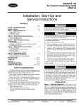
LIMITED TWO YEAR WARRANTY oN CRAFTSMAN
RIDING EQUIPMENT
For two (2) years from the date of purchase, if this Craftsman Riding Equipment is maintained, lubricated and tuned up according
to the instructionsin the owner's manual, Sears will repair or replace, free of charge, any parts found to be defective in material or
wori_nanship_
This Warranty does not cover:
•
Expendable items which become wom during normal use, such as blades, spark plugsl air cleaners, belts, etc.
•
Tire replacement or repair caused by punctures from outside objects,such as nails, thorns, stumps, or glass.
•
Repairsnecessary because of operatorabuse, negligence, improper storage or accident or the failure to maintain the
equlpmenta, ccordingto theinstructions contained in the owrier's manual,
'
•
Riding equipment used forcommercial or renta! purposes.
....
LIMITED 90 DAY WARRANTY
ON BATTERY
r ninety (90) days from date of purchase, if any batter,i inctudedwith this riding equipment proves defective in material or
workmanship arid our_testingdetermines the batte_;;wiHnot hold a charge, Sears will reptacethe battery at no chargeo
IN-HOME WARRANTY' SERVICE ON YOUR .CRAFTSMAN RIDING EQUIPMENT IS AVAILABLE AT NO-CHARGE FOR 30
DAYS FROM THE DATE OF PURCHASE. PLEASE CONTACT YOUR NEARESTSERVICE CENTER. AFTER 30 DAYS FROM
THE DATE OF PURCHASE, WARRANTY SERVICE IS AVAILABLE BY TAKING YOUR CRAFTSMAN RIDING EQUIPMENT TO
".,'OURNEAREST SEARS SERVICE CENTER, (IN-HOME WARRANTY SERVICE WILL STILL BE AVAfLABLE AFTER 30 DAYS
FROM THE DATE OF PURCHASE BUT A STANDARD TRIP CHARGE WILL APPLY.)THIS
WARRANTY APPLIES ONLY
WHILE THIS PRODUCT IS IN THE UNITED STATES,
Th!s Warranty gives you specific lega! rights, and you may also have other rights which may vary from state to state,
SEARS, ROEBUCK AND CO,, D/817 WA, HOFFMAN ESTATESI IL 60!79
:_ ",_': _'_'_ _i¸
_ :. L
:
:_ '_!_
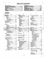
TABLE OF CONTENTS
,OPERATION ..........................................................
10-14
MAINTENANCE SCHEDULE ..................................... 15
SERVICE AND ADJUSTMENTS ........................... 20-25
STORAGE ................................................................... 26
TROUBLESHOOTING ........................................... 27-28
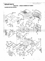
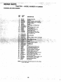
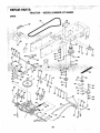
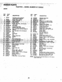
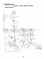
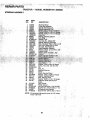
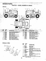
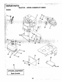
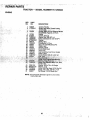
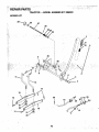
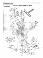
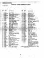
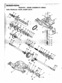
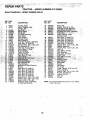
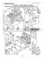
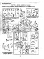
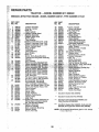
REPAIR PARTS -TRACTOR ................................ 30-47
REPAIR PARTS - ENGINE .................................... 48-53
PARTS ORDERING/SERVICE .................. BACK PAGE
SAFETY,RULES ............................................................ 2
PRODUCT SPECIFICATIONS ..................... :.......,...L..; 3
CUSTOMER RESPONSIBILITIES ..................... 3, 15-19
WARRANTY .................................................................. 3
TABLE OF CONTENTS ................................................. 4
INDEX ............................ ;............................................... 4
TRACTOR ACCESSORIES ................................ _......... 5
ASSEMBLY ............................................. .................. 7-9
INDEX
¢
O
Oil:.;
Cold Weather C0ndition_ ....... 13,1
Engine
t7
Storage .............................................
26
Operation ...... ,_._........................... 11-t4
Operating Mower ........................ _...... 13
...................................
-_,"
30-47
".."
.................
.............. ......._.,:.,_......... i _.,, ....... -,Fue!_.,,.._.,,_
............................. ,.... 19, ...... _.,..k.,_,.._^._,._., ,, , ,,
Removal/Replacement,: ...... ;,. 22
Blade:
Sharpening ................................... 16
Replacement ............................ L., 16
Brake Adjustment ..........................;......22
C
Carburetor Adjustment ....................... 25
Controls, Tractor .................................. 11
Customer Responsibilities .............. 15-19
Engine:
Air Filter .........................................
18
Air Screen, Engine .......... :......... t8
Battery ..........................................17
Cooling Fins, Engine ............ L; !8
Engine Oil ........;....................... 17
:" Fuel Filter ................................ 19
'
Spark Plugs ............... _,_
........ _.. 19
TractoP.
•
Blades ..,,._ ........................ ; 16
LubricationChad ................ _.... 15
M&intenance Schedule ....... _;_'.15
Tire Care ......................... 8,16,23
Cutting Height, Mower ....................... 12
Storage .......... _:........................... .'_
G
* R;-,.^
Gauge Wheels ................... :................. 8
H
Hood Removal/Installation ............... 24
L
Leveling Mower Deck .......... ,.o..,.:_.;_,..21
LubricationChert .........................
_............15
M'
Maintenance Schedule ........................ 15
Mower:
Adjustment, Front-to-Back .......... 21
Adjustment, Side:to-Side ...........:.. 21
Blade ShaqDentng .;........ :,.:.,.. .... 16
Blade ReplacemenL .........o.,o"....... t6
Cutting Height .:._
...........:";°':;i--;
12
installation; ...............:..;........ _. ......20
Operation :..................................... 13
Removal: ...... ......... ;...... :......_...._.,.20
Mowing Tips.::..: ........ ::o;.................. :. 14
Muffler ..,; ................. :......................... 19
Spark Arrester ........................ o. 3,40
Mulcher Plate ...................................... ; 9
,,
;,
_
'
Fuse _
24
Hood Removal/!nstallation ......... 24
Motion Drive Belt
Removal/Replacement ........... 22
Mower Blade Drive Belt
Removal/Replacement .......... 22
Mower Adjustment:
Front-to;Back ........................... 2!
Side-to-Side ........................... 21
Mower Installation ....................... 20
Mower Removal ............... _.......... 20
Tire Care .............................. 8,t 6,23
Slope Guide Sheet ............. ;................ 55
Spark Plugs ...........•.................................t9
Specifications ,_;.......,...................................3
Sta_ing the Engine
13-14
Steet'ing Wheel
7,23
Stopping the Tractor ........................... 12
Storage ::,.:._-.;.............i ...................:...... 26
T
Throttle Control Cable Adjustment ..:,..24
Tires ..... .......................................;,o8, t6,23
W
Warranty o:..;.......................
............ ;,.......... 3
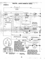
Wiring Diagram ............................. ;......30
Wirin'g Schemaiic :.......;_._.:..,':.o:
.......... : 29
?.
_......
22
Trouble Shooting Chad ....................27-28
Tran§axle Repair Parts ................. 46-47
4
:,i_:!
...........................
,Hemova_tHeplacemem..... ,.-.: zz
:' '," ,'i
,f_:
"
I
_'`'
.......................
'.
R_airP,a_s
_
•
,',",
........
,:,,,,_.
...........:_trnlnals
::
Options_
Accessories._, ............................... 5
, Spark Attester ........................... 3,40
P
Parking Brake ............................... t 1-12
Pads Bag ....... i...................................... 6
Pads, Replacement/Repair ............30-47
Product Specifications .......................... 3
.........................
'
;
...................
Battery:
Charging
7-8
' _ Cleaning ............................... ;........ 17
. .C6nnecting ...... _;........................ ,7-8
?:".:',; .i.__r:.,!_Sta_ing
with W_ak Batte_, ,.#_;,_,23,
Widng Diagram .............. ;L,.:....... 30
Engine',
Air Rlter..,.._ ......... ;....................... ! 8
Air Screen ................................... 18
Cooling Fins, Engtne '.................... 18
Oil Chdng_ .L.,_,.,. ..... =,o_..L.o._
..... 17
Oil Level ...... ;.......................... 13,17
Oil Type ..... ............. ;.................... 17
Preparation .................................. 13
Repair Pads ,.,,_...................... 48-53
Staffing.......................................... 14
Storage ....................................... 26
F
.; _Flltem: .......
• _,:,-:i.'
':'.:;':':_,::%_
;'
"','L /'•,,
if
25
'r
Carburetoro..................................
_
:.
r
v'!.
; _ "
' M6wer_
" ':
" Front-To-Back ........................ 21
i
Side-To-Side ..................... ;..o.21
.... -i:Throttle Control Cable....; ............ 24
• _AirFiti_i;Engine ....... !........................:o.18
; AirScreen, Engine • ........................ 18
:A_sembly ........................................... 7-9
B
,ii i:!
............
'_
J,.,_!.,,5
"
; ........
"_
..........
:"
:._:: _,-',_;;. Acce_ones;.._.4**r,,_.;._,_)
:
/
i,i'
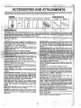
AIR RLTER
BLADES
BELTS
1
iit
. _: i, AERATORpI_0motes deep root growth for a healthy lawn,. Ta.i.! !.. pered 2_tnch steel spikes mounted on 10- nch diameter discs
:',' i:. [hunctijre h0}es In"s0il at close intervals to let'molsture soak In.
" Steel Weigli|'tray for increased penetration.
'
"
:'-
, an'd _re !design'ed for easy
r
#
_"
r
:
_'
;
"
_
"
_
%
:
_
44
#
i
"t
.in these attachments;(:
.
Contact i
;ssorlesandattachments
your tractor, .''_
_,.:, : .".
' " ,: _;
do not 'requi're additional hitches orconversi0n kits,(those that do are
::_',!.i,_vattachlngand detaching.' '
' ''
"
:SNOW BLADE for snoW:_
bar_
,lowers
ievers_ble scraper
i_0r rear drawbar
.
............ ! i youcollectgrass p ngs,and
leaves a
:nearer looking _awno _w0 vermanex containers hold
•
all0w.'mole: ';.:- ::'I
reach ;grass. roots. 36_inch sw;ath. 24
=''!
....
tips; t50 lb. Capacity weight tray.
spray i:
_ EASY Olt;'DRAIN VALVE n_akes oit changes easier, faster,
cides
...... "..... "
-,._
; FRONT
"
"' ....NOSE ROLLER canters in front of mower deck tO reduce
SPREADERJSEEDERSmakeSe_d
' '
and weed
Chances of %calping" on uneven terrain°
ing easy. Broadcast Spreader's_arealso useful r granular de-:_
icers andsand.
", _
_
GANG HITCH letsyoutow2 or;3pull:behind attachments at once,
Suchas sweepers, dethatchers., aerators (not for use with rollers,
SWEEPERS let you collect grass clippings and leaves.
cartslot other heavy attachments)°
TILLER has 5 hp engirie and 36-inch swath to prepare seed beds', ": 5,"!
GAUGE WHEELS on both sides of the mower deck reduce
cuffivate and compost garden residue, :Tiller_has its own bu It-in' :::_
Chancesof "scalping" on uneven terrain° For mower decks notso
lift and depth control system and does NOT require a sleeve hitch° :,;o_;_
equ!ppedo
Fits any lawn, yard orgarden tractor. Simpiy hook up to thetractor
_";i
!
MULCH RAKFJDETHATCHER loosens Soil and flips thatch and
drawbar and gol
Optional accessories
convert unit for !'.':i
dethatching aerating, hilling...without, tools.
'
., :. :._i!i
matted leaves to lawn surface for easy pickup° Twenty spdng fine
teeth, Usefuttopreparebareareas forseeding, Availablefor front
TIRE CHAINS are heavy duty; closely spaced extra-large cross .:,'._
or .rearl mounting, HIGH PERFORMANCE REEL-ACTION
links give smooth ride, ou!standing traction.
"
' •
SPRING TINE DETHATCHER covers 36-inch wide path and
TRACTOR
CAB
has
hea,,_y,
d
uty
vinyl
fabric
over
tubular"steel
i ;_!_
tosses thatch nto arge hopper. Mounts behind tractor.
,frame,'ABS plastictop; Clear plasticwindshield offers 360 degree ;i".i..i-'_i
'
MULCHING CLOSE-OUT PLATE KIT, once installed, lets you
visibility."Hinged metal db0mWitH catch, ..Keecs Operator warm i"'_i_
' mul.ch_ discharge or bag clippings (bagger optional)without
and dry: Remove vinyl.sides and windshields for use as sun i.";_
protector"I_tsumme]',. Optional:._iccess(_ries' include: tinted_i:i!ii!
i_
changing blades, For models not equipped as 3-m-lConvertible
: mOwers. '< See MOWER in the Repair Parts section of this
tempered _olid safety glass Windshieldwitt-_handoperaltedwiper; .if!,_;_
12-volt al_ber.caution tight'for mounting on cab top
: - ..!_. _
_; RAMP.TOPS AND FEET let you toad and Unload tractor from a
VACS for powerful collectio5 of heayy grass clipoines a='idleaves'-':? ;:_
;: I_iC!_Up
truck_: Usewith 2 xeor2x
101umber:
,
Optlor_al wand attachment to ptck;updebns in_ard-to-rea_;h ,, _
ROLLER.!fot Smoother lawn s_ifface, 36-inch wide,'18-inch
place's'. VAC!.CHIPPER !hc!udes a Ch!p'p_F-Shi'edder_
' ::_" <'/::L,I i_:
diameterwater.tight drum holdsupto390 Ibs. ofweight. Rounded
WEIGHT BRACKET for drawbar for snov_ t:e°movalapplications.i:) !!_.
edges prevent harm to turf. AdjustaUIe scraper automatically
Uses (1) 55 Ib.weight.
.........
: :"
cleans drum.
WHEEL WEIGHTS for rear wheels provide needed tract on fOP::il,il,.:
;.
snow removal or dozing heavy materials.
:
'
.... ,," !:';;
• "r
i"
.,
,._...
_
_ .,;_
_,,.;';_
!,_',
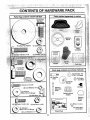
Parts Bag contents
shown full size
Parts packed separately
in carton
,(i) HexBolt
3!8"-16X 1
(1) Lockwasher 3/8
" '(1) Large FtatWasher
(1) Hex B0lt
•1/2-13 x 1
• Parts bag contents
•
(1) Washer
17/32 x 1-3116
x 12 Gauge
_
._
I
\
not shown full size
_
(2)Washers
:_/__,
x 7/8 x 14 Gaug e
/_,j ))
L./'//(2)
Gauge
Wheels
_
lock Nuts
_ '
.
"
, ,LookWos.eo
Washers
O
..
(2) Keys
Steering
Extension
Shaft
;"_'}
__3/4__6Gau_e.,L=_ j
.
. .....
.
Steel;ing Wheel
• •Adapter
(2) Weld Nuts ;#10 _!=J.,.
:
(2) Hex Bolts 1/4-20 x 3/4
G
(2) Washers
,Steering:
Wheel
insert
(2) Hex Nuts 1/4-20
!.__"X
(2) Latch Hook
Assembtys
9/32 x 5/8 x16 Gauge
((_
(2) Lock Washers !/4 'q_"
Slope Sheet
[',
6
!
,
,.
!_
L
:L
y
-
::'
'
i i i i j
ii i
i
i i
i
/_
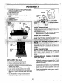
YoiJr new tractor ha,_been assembledat thefactory'wi{h excel_tion"of tllose parts left unassembled for shipping purposes°
To ensure safe and proper operation of your tractor all parts and hardware you assemble must be tightened securely,. Use
the correct tools as necessary to insure proper tightness.
TOOLS REQUIRED
FOR ASSEMBLY
A socket wrench set will make assembly easier. Standard
wrench sizes are listed.
(1) 5/16" wrench
(1) 3/4" Socket w/drive rachet
(2) 7.116"wrenches
Phillips Screwdriv.er "
.
,_ (1) lt2":wfen.ch
Tire i:iressurega_uge
, ...i__(;-I),9/..,t61!.
w_ench
,: Utillty_kdlfe ;i. ,.:L_,,
.'._L,
:,
.!..
'.:'::<;it'.'i',,W.
,hil_7+,_
g..ht)<qt,,_leff
;hand iS _r l+e.nlt#nlli÷l.n:;ihis
:manual, "it_.
'"
INSERT
318 HEX BOLT
_K WASHER
_,
-
',TO REMOVE TRACTOR FROM CARTON
""" .Remove all abcessibleibosb parts ana,6brts cartor_s
. :'::_.f,r.'bm=carton
(See l_age 6);,
_- i
;,
. ' =:.
* U!_,
Cdt, from top to' bottom, al0ni] lines on all four Co"mers ;"
: of carton, and lay panels flat .....
" . ....
,= .,.Check for any additional loose parts or cartons and
• remove.
:
:.
,.-'...
L"
ADAPTER,,.
,,
BEFORE
SKID_
ROLLING
TRACTOR OFF
•
,
:
•
,
." .
?
•
I :")'""'
-
EXTENSION
SHAFT
"" '"
5!16 HEX BOLT
6 hex_bolt
iMPOR_i_,Ii,_it: TI'GHTIENBOL"I:_AND
•lB'22,-:FT"LBS TORQUE_
" _:....
_.' _ :.i!
"
Place tabs of steering boot over tab slots in dash and
p,Jshdown to secure,
%
5/16 LOCKNUT
,r
INSTALL STEERING WHEEL
°
,,
Position front wheels of the tractor so they are pointing
straight forward°
Slide steering wheel adapter onto steering shaft extension.
=
Position steering wheel and sleeve assemblyso cross
bars are hor!zontal (left to right) and slide onto adapter.
° Assemble large flat washer, 318 10ck washer, 3/8 hex
bolt and tighten securelyo
° Snap steering wheel insert into center of steering
wheel,
•; Rembve protective plastic from tractor hood and grill.
IMPORTANT: CHECK FOR AND REMovE ANY STAPLES
IN SKID THAT MAY PUNCTURE TIRES WHERE TRACTOR
IS.TO ROLL OFF SKID.
: ' .
"
T0, ROLL :tRACTOR OFF SKID (See Opera;.','
ti0ii Section for location and function ofcon-.
tro!s)
•
Press lift lever plunger and raise attachment lift lever to
' : its highest position.
.
"
"
°
Release parking brake by depressing clutch/brake
pedal,
•
P!ace gearshift lever in neutral (N) position.
•. Roll tractor backwards off skid.
•
Remove banding holding dischargeguard up against
tractor,
,
#
/
I
LOWER
STEERING
SHAFT
i
FIG. 1
'
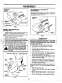
CONNECTBArrEm'(SeeFi s. and
CAUTION:
Do
not 'short
battery
remove metal bracelets, wristwatch
terminals.
bands, rings,
Before
etc. connecting battery,
Positive terminal must be connected
_' flrstto prevent sparking from accidental
grounding. _ i _
_;
:.
., . Rem6_,eCarboardi_aci_ing
fr_rh
seai
panancl lift seat '_i_:
_ pa n _0raL_edpos!ti0n, ....
•
•
°
°
;"i:
" : _ _
"
Be sure ba.tterY dralr_ tube is attache d :to battery box..i
Rem0_ie te_'mtnalpr0tectlvec.aps and discard.
If this battery is'put into service after month and year.
indicated on label (label located between terminals)
charge battery for minimum of one hour at 6-10 amps.
First connect RED battery cabte to positive (_-)termina!
with hex bolt, flat washer, tock washer and hex nut'as
shown. Tighten securely.
.L
: :
•
.
I=T
_:_
=
'connect BLACK grounding cable to negative (-) term[na! with remaining hex bolt, fiat washer, lock washer
. and hex nut. Tighten securely. "
. •Close battery box door°
Open battery box door for:
..
° Inspection for secure connections (to tighten hard'::'i;:i ware),
, :
.. • , lnspectibn for corrosion.
_':':'
PROTECTIVEI//I",\
,_';i
.:CAPS _//])]
'..
":
.....
:: WASHER
....
'
.
'
SEATPAN
SHOULDER
BOL.T
. ' :.
'
,'
WASHER
,
SEAT
;
,'::-
:
NEGATIVE
"
":,,
'
"
motion and
mbwer blade drive i0elts in
_ arid Adj'ustments
,-sectionof this manual : :Verify that the belts are routed
correctly_
':
•
:
CHECK BRAKE SYSTEM
BATTERY
BOX
DOOR
After .you learn how to Operate your tractor, check to see
that the brake is properly adjusted. See "TO ADJUST
BRAKE" in the Service and Adjustrnents section of this
manual°
ASSEMBLE
GAUGE
DECK (See Fig. 5)
FIG, 3
SEAT(See
.Fig, 4)
Adjust Seat before t!ghtening adjustment bolt,
Remove ca_rdb0ard packing onseat pan.
::= •Placeseat on seat pa.n and assemble Shoulder bolt,
!Ass e mblea dj's
u tmentbol,i ioCt<
was her_n d flatwasher
Ioo_ely_ Do n0ttighten.
-,"
.. : .
,:
Tighten shoulder bolt securelY.,
';_,- .
Lower Seat into operating position and sit on Seat.
° Slide seat Untiia comfortable position is reached Which
allows you to press clutch!broke pedal all the way
down=
Get off seat without moving its adjusted position.
Raise seat and tighten adjustment bolt securely.
•.
:,_:i:
;'::_!.
_..::
__;
.!.
mower housing 'should be properfy
OUSING" in the
PAN
:,
°
PRESSURE,
HSX
_h;iiiies o1_your tracioi:----'
were
-": "_b_erinilated at the factory for
..:. ;BOLT" _ 5 $_il_lStfig'PbrPOses. Cbrr_cttire press'ure ts irnp6rtant for
:.,.
:: best cLttting"Defformance,'.i
,.
,.
._".
i ;;. :':'
: : ,,:_iiRe'd(_e;"ii_:a'
pres_ure'!'t0 PSi sh0wn':in "PRODUCT
, :_ :-: SPECIFIGATIONS" on page 3 of this manual.
'
i
!
: !!!,::,.:__:_
.::
......
' '.
....
INSTALL
CHECK:TIRE
--- _.---:--_ - _--.---
•8
WHEELS
TO MOWER
Assemb.Ie gauge wheels with tractor on a flat level surface,
_, Adjust mower to desired cutting height (see .':TOAD" JUST MOWER CUTTING HEIGHT_' in the Operation
section of this manual). ' _ " '= "
,. -With .mower' in desired height of cut position, gauge
" Wl_eelsShould be assembled sb they are sUghtly off the
. gr0iJhd: Install gauge wheel ,in appfopriatehole with
-":-' s|pulder bblt, i3i8" washer and 3/8-i6 10cknut and
i' t!ghtens_.curely:,:
_":_.:... ? ,;.:
'_' ....
°
Repeat for opposite side installing gauge wheel in
same adjustment hole.
-
; :,,
_.:
'_
•
,_,
i:,._,./i.
,11,1,11
Ill
I
¸
:_
I_1'
_.
_!
_
"
,' ........, _,
,
_ 4
:,,,.
.......
_
,,..
.
_
i
••
,,,i .......
i
-_
i'
i
ii,:'_i.,
-•
Ill
,,,
[
_"
TO€O,w,TToBAGG'NG
o.
GAUGE WHEEL
MOUNTING
BRACKET
DISCHARGING
""_-
Simply remove mulcher plate and store in a safe place.
Your mower is now ready for discharging or installation of
optional grass catcher accessory.
k
./,
DEFLECTOR
........
? .... ':
FIG, 5
_
/}
"
_e
_'(S
_
'
r
_
_
_
_
' *,r
Figs. 6 & 7)
'
LATCH
_=: :Instal! two latch hooks to mulcher piate using screw,
.*_iash_r, lock washeK and weld nut as shown. : • _ '
HOOKS
NOTE: _.Pre-assemble weld nut to latch hook by inserting
. _,_weld;nut from the top with hook pointing downl,
_. _
:,
F!G. 7
•*!
:i
,/" All assembiy instructiohsf_ave been completed.
/
No rehlaining loose parts in carton.
,f
Battery is propeflyprepared and charged. (Minimum
1 hour at 6 amps)_
,/" Seat is adjusted comfortably and tightened securely,
WELD NUT FROM THE TOP
,/
HOOK POINTS DOWN
,/
WELD
LOCK
WASHER
J" Check mowerand drive belts. Be sure they are routed
properly around Puiley s and inside all belt keepers.
/
Checkwiring. See that all connections are still secure
and wires are pi'operly clamped.
WHILE LEARNING HOW TO USE YOUR TRACTOR, PAY
_XTRAA TTENTIOAI TOTHE FOLLOWING IMPORTANT
ITEMS:
•
.
Z
Engirle oi! is'at _'rbper levei_: '
NUT\\
LATCH
HOOK
"
LOCK
WASHER
WASHER
._
WELD
NUT
/
,z
,/
/
MULCHER
FIG. 6
9
_rr',
Fuei tank is"filledwith fresh, clean, regular unleaded
gasoline.
Become familiar with all Controls - their location and
function° Operate them before you start the engine.
Be sure broke system is in Safe operating condition.
i'
PLATE
{,'
All tires are property inflated. (For shipping purposes,
the tires were overinflated at the factory),
Be sure mower deck is properly leveled side-to-side/
front-to:rear for best Cuttingresults. (Tires must be
propedy inflated for leveling)°
•
..........._:i_
_I_!_
....................
,,........... _...................
_,,,,_,_
.....
,,_ :,_:,_,_
OPERATION
_
•_'".
_:
_.
;
ui
i
ii
r
]'
• *;_[,A
'
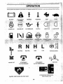
These symbols may appear or] your•tractor or in literaturesupplied with the product, Learn and understand their meaning,
::,>.:
-
:BA_ERY ,_CAUTIQN_0RREVERSE
[-
ENGINE OFF
._. , . 'ENGINE ON
REVERSE
I
OIL PRESSURE
NEUTRAL
HIGH
LOW
=ARKING BRAKE
:
!{
,!
A_CHMENT
MowER LiFT
(3LUTCH ENGAGED
lfi't
D6NGER, KEEP HANDS AND FEET AWAY
t
•
_,
,
;
:
_ii'ili iGNI"I:ION !
.
,
.*,_,_
-4-.
_ _,,
'_,_;_,
.
_
_
......
,_
,;
.
• _•" .....
_."
_-_,
_x _ ._
'. .....
,,
_
_ • ',.',= _" _ _ "'_
. _ . _.
,.
_":_••_ _ _•_ ' ' ':
•
_ _
• .
•: _ "..
,-,.,
_' •':
,_
!_ :•'_ _."."•'_'_"
- , ,,,
,
,
,_
' _ '_'•
_
:"
_;';'.'
,
;_ ',_•_"_'_'_;_"";_
¸"
,, _,
._
, ....
':_ _":,_ ,_:;;':."
• _
,_
:_-
•_! i,_-'•':•;!_ "'_¸
•
_i ¸•' "i_':_,',:'!_
. 3j
,%
•;'
• ,
_ : .....
......
..................................
,
KNOW YOUR TRACTOR
READ THIS OWNER'S
,
: _
MANUAL AND SAFETY RULES BEFORE
OPERATING
YOUR TRACTOR
,,
Compare the illustrations with your tractor to familiarize yourselfwith the locations of various controls and' adjustments. Save _,::
:thls manual for future reference,
ATTACHMENT
CLUTCHLEVER
' i""
"
. AMMETER
....
..,.:.•
_IG BRAKE
,i
FIG.8
Our tractors conform to the safety standards of the American National Standards Institute,
ATTACHMENT CLUTCH LEVER: Used to engage the
_0wer bl_.des, or Other attachments mounted tO Your
tractor.
. :
GEARSHIFT LEVER; Selects 'the speed and direction of
tractor,
ATTACHMEN"r LII_ LEVER: Used to raise and lower the •
mower deck or otherattachments mounted, to your tractor,
_,'"
LIFT LEVER PLUNGER: Used to reiease attachment lift ' i;,,i_
lever when changing its position.
"'
_ '
UGHTSWITCH: Turns theeI_eadlight;son and off,
THROTTLE/CHOKE CONTROL::: Usedfo; staffing 'and
cbntr_iling engine speed,
CLUTCH/BRAKE PEDAL: Used fordeclutching and brakIng the tractor and starting the engine,,
IGNITION SWITCH: Used for starting and stopping the
engine, '
'
HEIGHT ADJUSTMENT KNOB: Used to adjust the rnower "
cutting height ......
PARKING BRAKE: Locks clutch/brake pedal into the
brake positior_.
AMMETER:
(-).
i•
11
Indicates battery charging (+) or discharging
:
The operation of any tractor can result in foreign objects thrown into the eyes, which can
result In severe eye damage.Always wear safety glasses or eye shields while operating your
tractor or performing any adjustments or repairs. We recommend a wide vision safety mask
over the spectacles or standard safety glasses.
r HOWTO USE YouR TRACTOR
',
,
_! _:'_'_:;T'n
._T
..... -, _ ,.:,:,.......
,
hm'E:
....
.
pAI_KiNGBRAKE IS_
: _ .....
_ .....
Fit_, 9'1
,.: .... ._.0_
..... _........
, .,- .....
..".r;__.-,.;,:sw_t(}h,":'
When:,ertglne:_S:..mnntng; any.attempt ..by the _
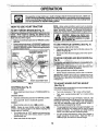
Under certain conditionswhen tractor'is standing
idle with the engine running,hot engine exhaust ga:sesmay
cause "brbwning" of grass, To.eliminate this possibility,
a!V_assto en Inewhensto
tn tractororl tassareas.
I,
__:' ':: P_^_rn'n_._."_^_,,,_
=,,_, ,,._,_,-,, •_,_,,,.
I
._:,
i :i_:',i
'•;
_:t
ir
_',
::_,;
'_'
.#'f'
. " \
':':"CONTROL
"
,_POSITION"" ,
"TO MOVE FO RwARD
:_
AND BACKWARD
;ed and
' _.::
. ":_
'i""
•
:_;!
CLUTCH/BRAKE PEDAL
"DRIVE" POSITION
...I
"DISENGAGED"
\
PosmoN
TO DO SO WILL SHORTEN THE USEFUL LIFE OF YOUR
TRAN SAXLE
FIG. 9
:
,
(See Fig. 9)
TO ADJUST MOWER CUTTING
.(See Fig. 9)
HEIGHT
The cuttingheight iscontrolled by turning the height adjustment knob in desired direction.
°
°
• ..Depress clutch/brake pedal into full "BRAKE" position°
The cutting height range is api_roximately 1-.1/2"to 4". The
• _ Move gearshift lever t0 neutral (N) position,
heights are measured from the ground to the blade tip with
the engine hot running. These heights are approximate
and may Vary depending upon soil conditionsi height of
grass and types of grass being mowed_ .. '
_
4"
r
ENGINE _
' = _ Move throttle controlto stow (,_)
I
° •Move attachment clutch lever to "DISENGAGED" po: .Siti°n°
GROUND DRIVE -
position, _
_ •
_:NOTE: Failul'e to move throttle control toslow (,_!,)
position and allowing engine to idle before stopping may
cause engine to "backfire",
° "T'urn ignition key to "OFF" position and remove key.
' Always remove key when leaving tractor to prevent
IJnauth0tized use_
,,
':
position_
•
Slowly release ctu{ch/brake pedal to start movement.
IMPORTAN'[: BRING TRACTOR TO A COMPLETE STOP
BEFORE SHIFTING oR CHANGING GEARS. FAILURE
MOWER BLADES -
:
,
HEIGHT AD,_USTMENT KNOB
"
STOPPING
MoVe gearshift` lever todesiied
•:"
(See
Never use choke to stop engine°
*'
•
Turn knob clockwise (/_t) to raise cutting height.
TLim knob counterclockwise (IPL--_)to !ower cutting
heighL
'
TheaveragetawnshouldSecuttoapproximately2-1/2
inches during the cool seasonand to over 3 inches ....
during hot months.. For healthier and bettei' looking
lawns, mow offer} and after moderate growth.
.
For best cutting performance, grass 0vet 6 inches in
height should be mowed twice. Make the first cut
relatively high; the second to desired height,
i
TO OPERATE
MOWER (See Fig. 10)
•
Your tractor is equipped with an operator presence sens_
ing Switch° Any attempt by the operator to leave the seat
With the engine runningand the attachmentclutchengaged
w!l! shut Off the engine.
.
TO
,llllll i,, i i
..........
...................
To restart movement, slowly release parking brake and
clutch/brake pedal.
Make all turns sl0wly.
TRANSPORT
°
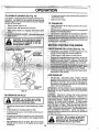
Fill fuel tank. Use fresh, clean, regular unleaded
'gasoline with a minimum Of87 octane, (Use of leaded
gasoline will increase carbon and lead oxide deposits
and reduce valve life)o Do not mix oil with gasoline.
Pu_:chasefuel in quantities that can'be used within 30
days to assure_fuel freshness.
'
IMPQRTANT: WHEN OPERATING IN TEMPERATURES
BELOW 32°F(0_C), USE FRESH, CLEAN WINTER GRADE
GASOLINE TO HELP INSURE GOOD COLD WEATHER
STARTING.
DISCHARGE
GUARD
FIG. 10
TO OPERATE
i_ CAUTION: Do not drive Up or dOWn
• hills with slopes greater than 15 ° and
.....
,!
|
....
....... d° not drive across any slope.
•
_
WARNING: Experience indicates that" alcohol blended
fuels (called gasohol or using ethanol or methanol) can
attrai:t'rnoisture Whichleads t0 Separ_.tion and formation of
acids,idUi'in'g storage: • A0idJo gas _can damage the fuel
system6f_an engine While in storage. To avoid engine
Croblems, the fuel system should be emptied before stor:
age 0f_30_days or longer.: Drai'n the gas tank, start the
englpe add let it run untii the fuel I nes and carburetor are
empty, i use fresh fuel next Season. See Storage InstructiOnsi{oi';"ad_iiiohal informati0no' Nearer use engine or !:
carb_retS'r"€leaner products in the fuel tank' or permanent
damage _may Occur.
ON HILLS
:
;
I
.
C_6os'ethe Slowest speed before _tartidg Up or down
,_ : Avoid stopping or changing speecl on hilis'o
!
°
If Slowing is necessary, move throttle control lever to
slowerposition.
•
If stopping is absolutely necessary, push clutch/brake
pedal quickly to brake position and engage parking
brake_
:
Move gearshift lever to 1st gear. Be sure you have
allowed room for tractor to roll slightly as yo u restart
movemenL
CAUTION: Fill to bottom of gas tank
filler neck, Do not overfill, Wipe off any
spilled oil or fuel. Do not store, Spill or
use gasoline near an open flame.
u
.13
.,:: i_,_
._
, :
: .
OPERATION
....
TO START ENGINE
(See Fig. 9)
*
When Startingengine for the first time or if engine has run
out of fuel, itwill take extra crankingtime to movefueHrom
thetank to the engine......
When operating attachments, select a ground speed
that will suit the terrain and give best performance of
the attachment being used.
......
: : ................
.
= : Depress clutch/brake peda! and set parking brake.
. _'_ • • Place gearshi,ft lever in neutral (N) position.
F
----..---
_;":_;;'; iMove atta(;hment ciutch to=DISENGAGED"posi{i_n,
.._
"
' -_
......;
...............
.,_'_
"_
"
' '_
:.
,_,,
I
:i).;i
J
::'._'
p0Sition;
i,:',..,',:",;.
Wfie'ne'r
:,
"
.tryagain: :_ "_i.. _?:.:i
::
'
" ....
_&.
FOR
.........
11
*
-
"" '
J?i"
':_
""
BEST PERFORMANCE,
KEEP
!:'i
='_";:
MOWER .HOUSING FREE OF BUILT-UP GRASS AND
:'
_RASHo ,CLEAN AFTER EACH USE.
"
':';
i * The special mulching blade will recut the grass clip':"i
timeSthe
lawriandtheyreduce'_
them in size so thatgrassaS.i"ii'
i_not{ced.: _Als.o,
rass witi
.....
grasstends " '
to
interferes withthe mulching action.
The best time to mow your lawn is the early afternoon.
At this time the grass has dried and the newly cut area
will not be expose d to the direct sun.
For best results, adjust the m0wer cutting height So that
the mower cuts offonly the top one-third of the grass
blades (See Fig. 12). For extremely heavy mulching,
reduce your width of cut and mow slowly°
"
_r
should be prope_'|yleveled ira"
;t mow_g
performan'¢e: See"TO LEVEL MOWER HOUSING in
:,"i,
._ the Service and Adjustments section of this manual
-. The left hand side of mower' should be used for trim': ruing.
."
.
:'
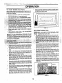
Ddve so that clippings are discharged onto the area
that has been cut, Have the cut area to the right of the
machine, This will result in a more'even dtstrib0tion of
. _c.lippirlgs and more uniform cutting.
o:-: When mowing large areas, start by turning to the tight
so that clippings will discharge away from shrubs,
!ences, driveways, etc. After one or two rounds; mow
in the opposite direct!on making left hand turns until
fin!she d (SeeFig: 11 )_
""
.
' " "
•,-. If.grass is extremely .tall, it should be mowed twice to
reduce load and possible fire hazard from dried clippings..Make first cut relatively high; the second to the
desire,dhq!ght, _
" , . ; . .
.
..
=-. Do not mow grass when it is wet. Wet grass Wiflplug
mower and leave undesirable clumps, Allow grass tO
,_r'" allY'before mowing.
. •
: ....
/""
AlwaYs Operate e_gine at full throttle When mowing to
'
assure better mowing performance and proper discharge of material, Regulate ground speed by select'.
ing a low enough gear to give the mower Cutting
. performance a s welt as the quality of cut desired.
_'
"
,
_ A_low engine to warm Qp'fora few mihU{es .6ef_r'e*
.:. engaging drive or attachmentSo
: ; ,...:.,::-.i :
iMPORTAN;r:
NOTE: if 'at a high altitude (above 3OOOfeet), or in cold
temperatures"(below 32 F), the CarburetOr:fue! imtxture
•
mayneedto bbadjusted for best erigineiCeffOrmance: See
. !";'g'O
' JST CARBURETOR" tn the Service and !Adjust.....
manual. ',
''
''
kk
" _"_:""' ........
move:throttiecdrltr01to_esired,
Certain types of grass and grass conditions may require that an area be mulched a Second time to completely hide the clippings. When doing a second cut,
mow across or perpendicular to the first cut path.
Change your cuttingpattern from week to week. Mow
northto south one week then Change to east to west the
next week. This will help prevent matting and graining
Of the lawn.
t
FIG. _12
14
RESPONSIBlUT|ES
Check Brake Operation
if
Check Tire Pressure.....
T
.
_ I_
Check fOr Loose Fast,ners
.
|V
SharpenlReplaceMowerBades
0
Clearl
Battery
arli]Term[nals
; I
?./+,
if
t_
P
.
'
"
I
1 "
.....
+'
l_.
!_4
_.....
-
_.,_.
"
"
'
i##', '
'
'
• _,,
i:::: :A_j_stM°tj_nDdveBelt(_) Tens!oil . .
'.
'
i
:"
i:i:_:::Vs
=
':i
::i:'
'
. .....
': $_'5 ..... :
_ .....
"
'
|
:; :AdjdstBadeB(_ltis):TehslonY
_ i:. ':- ! . ' _+ :
_" +', •
'" .....
,
," ....
:-.
:
t
-
i:":::_:
' '
:'
"
', +," +,_.,, .+
_"t--,_
;"'
..... _.: .....
:'.
:::::I :
'
i:.
':;:i:, !!:!:. , ::
..... Che E
k ngram"
o, Le i;""::":: "
Change EngineOil" .:'
:. .....
:'+
'
" 3_. if equlpppd win'oil filter+change oil every 50 hours, +._ "'
' " : + :;4- Replace blades more Oftenwhen mo'wing in sandV soil
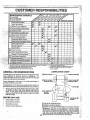
GENERAL RECOMMENDATIONS
Th'ewarrantyon thistractor does not cover items that have
been subjected to operator abuse or negligence+ To
receive full value from the warrant,!,operator mustmaintain
tractor as instructed in this manual.
Some adjustments will need to be made periodically to
properly maintain your tractoro
All adjustments in the Service and Adjustments section of
this manual should be checked at least once each season.
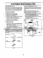
®
BEFORE EACH USE
• ; Che+€
k engine oil level°
•
Check brake operation+
,
Check _tirepressure.
= Check for loose fasteners+
® CLUTCH
:
:;[
PIVOT(S)
=
'
"
'
.
......
"
,,: Once a year you should replace the spark plug, clean
. : Or replace air'filter, and check blades and belts for
. • 'wear: A new spark plug and clean air filter assure
proper air-fuet mixture and help your engine run better
' . andlast longer.
.::
{
+_
.
F
PIVOTS
[
"
(_) SAE 30 OR 10W30 MOTOR OIL
@ GENERAL PURPOSE GREASE
®
.
15
REFER TO CUSTOMER RESPONSIBILITIES
"+ENGINE" SECTION
::
': _+,
::i,i''!
1MPORI:ANT:"
DO NOT OIL OR GREASE THE PIVOT POINTS
,!;.!i
WHICH HAVE SPECIAL NYLON BEARINGS . VISCOUS LUBRt-: +_+_
CANTS WILL ATTRACT DUST.AND DIRT THAT WILL SHORTEN++_+I'+_::i
THE LIFE OF THE SELF-LUBRICATING
BEARINGS
IF YOUiS'._-::I
+
FEEL'THEY MUST BE LUBRICATEDI
USE ONLY A DRY, POW-:II'_:_,'_
DERED GRAPHITE TYPE LUBRICANT SPARINGLY,
"
.,_._,.
TRACTOR
MANDREL
Always observe safety rules when performing.anyma!nten_nce.
• ,,BRAKE OPERATION
.... If
_i._
_•_
_":.;','
"_"
more than six (6) feet Stoppingdistance
in highest gear_then brake mustbe adjusted.
ST BRAKE In the Set'vice and A_ljusF
thismanual). '. ;_
' "
_
, ,
,'??_
NOTE; Do not use a nail f0_b_lan,c!ng t_ladeJ The lobes of
the center hole may appear to be centered, but are not.
NOTE; We do not recommend sharpening blade- but ifyou
do, be sure the blade is ba_anced_
=
_/8" B
,:. :_
16
BLA.,,,DE
FIG. 14
-. -
• • •
....
CUSTO
BATTERY
NOTE; Although multi-viscosity oils (5W30, 10W30 etc.)
improve starting in cold weather, these multi-viscosity oils
will result in increased oil consumption when used above
32°F. Checkyour engine oil level more frequently to avoid
possible engine damage from running low on oilo
Your tractor has a battery charging system which is sufficient for normal use. However, periodic charging of the
baffery with an automotive charger will extend its life.
°
,,
Keep battery and terminals clean.
Keep battery boltstighL
,
KeeP.Small vent holes Open.
Change the oil after the first two hours of operation and
every 25 hours thereafter or at least once a year if the
tractor is riot used for 25 hours in one year.
Ctteck the crankbase oit levei:befoi'e starting the engine
and .after each eigSt (8) houi's Ofoperation. ;,Tighten oil till
, cap/dipstick sec_r.e!y,_ach time yog,lcrieck l_heoil level
'::'
b_tern_ideterfi_e_bi:er'_Hge
exPectedbef6re oil change.
,is6onnePt BLACK battery cable first., then RED bah'
i_ Cableand refd0$eba.ttery fi'6m tractor. ......
;
inse the battery with plainwater and dry°
_ "
Iear_t_rminals and batte_:(_ibie ends with wire brush
dilbright.
:
:"
"
_ai termirlals with grease:'_':_:bt_roleumjelly,
" .:' ',"'/ Reinstall battery (See "CONNECT BATTERY" in the
: . i. " Assembly section of this manual).
All oilmust meet:A?i s_erviceclassification SFor SG.
-".. Be sure tracio¢is Onieveisurface,,
°
Oil will drain m0re freely when warm.
Catch oil in a.suitable €ontaine n
Remove oil fill €_ip!dipsticko Be careful not to allow dirt
to enter the engi.ne _/lien changi'ng oil
Remove drain Plug.
.
After oil has drained completely, replace oil drain plug
and tighten se.curely.
•
o hotl felldipstick tube. Pour
see
this.
ms_le free fr'om build-up of dirt•and cl_affwliich
.ca.n'restdct
cooling.
ILL
CAP/DIPSTICK
'ENGINE
LUBRICATION
Oniy use high quality detergent oil rated with API service
€lassificationSF or SGo Select the oil'sSAE viscositygrade
according to your expected operating temperature,
OIL DRAIN
PLUG
SAE VISCOSITY GRADES
FIG, 16
"F
'-20'i
°C-30"
:
"
'
0"
-20 = "..
:
i.-:tO'.
30"
"
:32"
0"
4o"
"
,
60"
10"
.
80" .
20'
30'
lo0'
40'
17
':"
:,
ii._
,
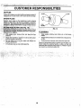
AIR FILTER (See Fig. 17)
_
CLEAN AIR SCREEN(See
Fig. 18)
Your engine will not run properly using a dirty air'filter°
Clean the foam pre-clean_r after every 25 hours of operat on or every season, Service paper cartridge every 100
hours of operation or every season, whichever occursfirsL
Air screen must be kept free of dirt and chaff to prevent
engine damage from overheating=.Clean with a wire brush
or compressed air to remove dirt and'stubborn dried gum
fibers.
Service air' cleaner more often under dusty conditions.
,_ Remove knob(s) and cover.
ENGINE COOLING
FINS (See Fig, 18)
'_:
Remove any dust, dirt or oil froni engine cooling fins to
preVent _englr_edamage from oVerhea!!ng.'.
_
:_'._
,. ;,,, and d psttck_td_e,asi_bf_bly.
_ff;ei_jjlne_ _'_ ,Y:: 'i "_:
,
:
• _.
06vet oil filt op'_ptn'gto:pi'_Ve_t_ent_ 6.f dirt;'
."
€lelahengine c6011ngfinsi:i;_:i ::, : , , '
To reasse_hl_ie.i:i;evei's_abgve piOceclure..
": ,. if Vehj dirty Or'damaged, fe_plac6i_re_cleaner, _;'
•
:i'"
:_i,i
Reinstall pre-cleaner over cartridge,
Reinstall cover and secure with knob(si.
TO SERVICE CARTRIDGE
'
-
Remove cartridge nut,
Carefully remove cartridge to prevent debris from entering carburetor. Clean base carefully to prevent
debris from entering carburetor.
',
CARTRIDGE.
•o
,
!
.
PLUG
COVER KNOB
ENGINE COOLING
FIG. 18 FINS
COVER _
_j
CARTRIDGE NUT
PAPER
CARTRIDGE
/
FIG. 17
_
I
18
i
,
'
•
CLAMP
Inspect and replace corroded muffler and spark arrester (if
equipped) as it could create a fire hazard and/or damage+
• SPARK
PLUGS'
_: Repiace spark plugs at the beginning of each mowing
_+easonor after every 100 hours of 0pemti0n; whichexJer
° + Occui'sfirst:: Spa_plug type +andga_5setting are shoWnin
+,:'+-,
._PI_QD.+UCT
SPECIFICATIONS' on page 3 ofthis manual.
,.+,:.:.: ,_L+_:+;_.L:,,+++;;':;+:+.:;:;:
;::-,++,.,
:+_+:_.:.<j.;,.;+u_,,:
_+,`
:.-. +:, . :. +, ' ,, :. ,. + _.:j::_'+++.'
...:.......
.
:":.',:'+:+,'_"_'_''+;
!
'"
t
+ ......
::_',++
.t'"+
+'
.
+'+-'+'
'
.+'_'"
"
,"
+;
'":.
,
FU_,,
r+_!_.n"
..
'
/
+/
'
.
'
..'
'
"
,+!_._.':,¥+,'+_+,++, _ tq_!+,_'++_,+,:_+.+_,j_+.,,,j,*_++_.,,÷-,;,_++.,+_
+,-.++ ,, +/'.
+, + •_ ......
?.,.,..+,,.
.,,,
,,
.,
_
+, . _
.,+ ........ +
/
: .,'
.............
..... .,.,,,,,+.,,,+,-,+.,
....... ..,., • -..+,+,.....,...,_
•++ ................
FIG. 19
y}++.':_+..:r:!_,e+f.+_el:_ittersho_!d,
be,,r.epMced
once each seasop.,tf fuel;
; ...-:, ; +._, ' : + ., '
+,
,.:,;
_
,_..
.,_,._+++
_
._:..._:+.
,+.,+,_,.++
.
+.,+
:
,..+.
+
+.
,,,,_
:
ii_.
•
;,
++.:
. _....
L+;'
' ,+:,.._-+fJltet+:b_comes
clogged,
obstructmgfuel
flow
to
carburetor,
.........
....= . : . ++.
+: .....
_'.'+::+:rei_l,det_ent:is
mqui_ed_:+,+
'::" ;
" .. "
'+ ,t , . . ' .
CLEANING
.:" : "t
,",-.,,
• , +:+
,
.
,
, ,+
• *
.,,
,,
;
,
:+W_t_
'_
_'
_
;
;'
:
L'
+_
.ehgin+';'c+001,'remove filter and plug iuel line
i +__ :,: _ectlon_: :,:;:_,"
+, +" _ :',
: :
.:
+,_!"_
''
"
:
•
Keep finished surfaces and wheels free of all gasoline,
oi!, etc.
:
'
.
Protectpainted surfaces with automotive type wax,
+"'..+:
• --""
.
We do not recommend using a garden hose to clean your
tractor unless the electrical system, muffler, air filter and
cal'buretor are covered to keep water out. Water in engine
can result in a shortened engine life+
,
+
....
"
I
- properly P0sitione,d_.
";i
......•
"
Immediately wipe up any spilied' gasoline.
i
°
.
0 . G!eall+ehgine, battery, seat, +finish, etc. of all foreign
:+,,i! matter:.: + ' "
' :
'
,,+
- • ..=_
o
'
°
J
;"
+4_
'
"}
:
'! =. +,ptace new fuel filter in position in fuei line w th arrow
:polntingt0wardsdarburefor:"
" " . ::::.,+ _ : .:
'
; :::.Be sui;e there are no fuel line leaks andcl_rnl_'S are
,
. .!
,,_
. +-_.,, :.,., •
+;_
+'r
:19
.
,
;
...
SERVICE AND ADJUSTMENTS
:
I
q,
IIII
l'l'l"lllll!lll
, ii M'
CAUTION:
I
I
I I
'III
L
'I
,i U
I
,
!ii
........................
BEFORE PERFORMING ANY SERVICE OR ADJUSTMENTS:
Depress clutch/brake pedal fully and set parking brake,
Place gearshift lever in neut_l'(N) position.
Place attachment clutch in "DISENGAGED" position.
Turn Ignition key "OFF" and remove key.
Make sure the blades and all moving parts have €ompletely stopped.
Disconnect spark pt'ugwire from spark plug and place wire where tt cannot Come in contact with
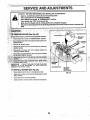
MOWER (see Fig. 20),
:.....
_'
.....
:
libe ea'slerto remove from the dghtside of,tr'actor.
"Ciutchin "DISENGA(3EI_" t_bsition,
RETAINER
SPRING
!_i_;;:_:!,
_;i ,:,'*Moveattacl_ment liftlever' forWard toloWermoWer to its
_i:!_i ,_: i;::JdWest'posltion. '
: : :" :- : : :'>....
. '
SUSPENSION
PULLEY
:_:_:"/' _ L':!Rollbelt Off etlg ne pulley.
.
.
.
'_:'., =, ' Disconnect clutch rod from clUtCh;lever by removing
, _ =':,,::_i:retatnerspring.
-=
•
,...
_.-..
: Disc0nnect sus
RETAINER
SPRINGS
=
'
'
"
'
I
'
:
'
'
1
=
::i
..:,: ,_., D_sconnect ant_-sway bar from chassis bracket by
! ._ : remoVihgretainer spring.
arms from rear deck brackets,
rSPRING'
_ ;_-_
IF AN ATTACHMENT OTHERTHAN THE
' "' MOWER
IS TO BE MOUNTED
TO THE TRACTOR,
_ REMOVE THE FRONT LINKS.
*
TO !NSTALL
, !;;'
AN+I'_WAYBAR
MOWER (See Fig. 20)
:..Raise attachrfient tift lever to its highest posltion_
"
Slide mower Under tractorwith d_scharge guard to right
side of tractor.
'
FIG. 20
o Lower lift lever to its lowest position.
•°
Install mower in reverse order of removal instructions.
20,
-+
RETAINER
SPRINGS
(BOTH SIDES)
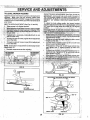
Adjust the mower while tractor is parked on level ground or
driveway. Make sure tires are properly inflated (See
"PRODUCT SPECIFICATIONS" on page 3 of ttiis manual).
lftires are over or underinflated, you will not property adjust
your mower.,
:SIDE-TO-SIDE
IMPORTANT:
DECK MUST BE LEVEL SiDE-TO-SIDE
IF ":
THE FOLLOWING
FRONT-TO-BACK
ADJUSTMENT
IS
NECESSARY, BE SURE TO ADJUSTBOTHFRONT
LINKS ',,
EQUALLYsIDE
° ,:: SO
To obtain
MOWER
WILL STAY LEVEL
the best cutfing:
SIDE-TO-
results,, the; mower
'
:ii
,.";i
(See Figs. 21 and 22)
ADJUSTMENT
Raise mower to its highest position. '
,_ _ nuton that sider'
'i:iSi:ii:'i!.!i-:ii_°w_
, about'
_,h'e!ght
NOT.!
of mower, tighten lilt link adjustment
;; .
hr°tnii?:l_e °f re°we r, 'o0sen lift link.adjustment
.....
E,_chfull
mower1/8.
°turn of adjustrfiehi ,LIt Willchang e
- '_:i::
I'
I_lech;ck
measurements after
adjusting:
BOT_'0MEDGE
,;OFMOWER TO
"".
,,"
BOTTOMEDGE
OF MOWER TO
.'GROUND _': ""
" /
;.
"'_
,
RG. 21
SUSPENSION
ARM
FIG. 23
•
BOTH FRONT I.INKS MUST BE EQUAL IN LENGTH
LIFT UNK
ADJUSTMENT NUT
,+
FIG. 22
i
:
.......
::!.
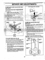
TO REPLACE
(See Fig. 25)
MOWER
BLADE DRIVE BELT
The mower blade drive belt may be replaced withouttools._
Pa_ the tractor on level surface. Engage paNing brake.
.'i,_:,BELTREMOVAL - '
PULLEYS
"UCW_¢ds'
;
MANDREL
PULLEY
FIG. 25
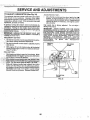
TO ADJUST
Pull beti ioward fr0n(of tr,_ctorand remove downwards
from aroudd engine pulley.
Install new belt by reversing above procedure.
IMPORTANT: MAKE SURE UPPER BELT KEEPER IS
=OSITIONED PROPERLY BETWEEN LOCATOR TABS.
BRAKE (See Fig. 26)
Your tractor ts equipped with an adjustable brake system
whlch is mounted on the right side of the transaxle,
PUL:LEV
CI_UTCHING
IDLER
TABS
" tf tractor requires more than six (6) feet stopping distance
at high speed in highest gear, then brake
must
be adjusted.
,j
,
,
.
.
°.
Depress clutchibrake pedal and engageparking brake,
Measure distance between br&ke operating arm and
• nut "A" on brake rod.
° :' If distance is other than 1-1/2", loosen Jam nut and turn
nut "A" until distance becomes 1-1/2". Retighten jam
' nut against nut "A",
.
'" .. •
Roadiesttractoriorpr0per
st0pplng'distance as stated
"
above° Readjust tf necessary. If stopping dtstance Is
still greater ttlan stx (6) feet in highest gear, further
maintenance is necessary. Contact your nearest authorized service center/department°
'
BELT
KEEPER
IDLER
PULLEY
!
FIG. 27
_:::
AND ADJ
TRANSAXLE SHIFTER LINKAGE AND ADJUSTMENT (See Figs. 28 and 29)
The transaxte should be inneutral when the gear shift le've_:
.is in the neutral (N) (lock gate) position. The adjustment is
preset at the factory; however, if adjustment is needed,
proceed as follows:
i. , Make sure transaxle is in neutral (N).
_,
on tie r0d.
CENTER ROD
CAUTION:
TIE ROD
and
smoking gases.
materials
away
fromflame
batate explosive
Keep
Sparks,
teries, Always wear eye protection
when around batteries.
_(:_
;
Lead-acid batteries gener-
TRANSAXLE
,,,, !,
: FIG. 29
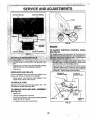
TO ADJUST STEERING
WHEEL ALIGNMENT
If steering wheel crossbars are noi horizontal (left to right)
when Wheelsare positioned straightforward, removesteeringwheel and reassemble per instructionsin the Assembly
sectibn' Ofthis manual.
.....
-
FRONT WHEEL TOE-IN/CAMBER
........................
If your battery is too weak to start the engine, it should be
recharged,. If "jumper cables" are used for emergency
starting, follow this procedure:
IMPORTANT: YOUR TRACT.OR IS EQUIPPED WITH A t 2
VOLT NEGATIVE GROUNDED SYSTEM THE OTHER
VEHICLE MUST ALSO:BE A 12 VOLT NEGATIVE
GROUNDED SYSTEM: _DO NOT,USE YOUR •TRACTOR
BATTERY: TO START OTHER VEHICLES,.
TO ATTACH JUMPER cABLEs"
• " Connect each end oftt_e RED cable to the POSN'IVE
(+) terminal o.f each'battery, _tai<ir_gcare •not to short
:against chassls_ _ _..;-_..... ._.. ,, .
: ....
"•
°
The front wheel toe-in and camber are not adjustable on
your tractor. If damage has occurred to affect the front
wheel toe-in or camber, contact your nearest authorized
service center/departmento
23
Connect one end ofthe BLACK cable}o theNEGA:
TIVE (-) terminal of fully charged battery_
Connect the other end of the BLACK cable to good
CHASSIS GROUND, away from fL_eltank and battery.
TO REMOVE CABLES, REVERSE ORDER •
BLACK cable first from chassis and then from the fully
charged battery.
°' RED cable last from both batte_'tes_
t
_ _
.
::7:_i ! ; ::: .......
; .......................
?i:
POSfflVE TERMINAL
HOOD
CABLE
at the .factory and
ustmentas
iS: ';i:'!i"
""
r
Replace bulb =nholder and push bulb holder securely
:' back into the hole in ttie backside of thi_ grill.
• .Close hood.
'
.
#.:
_'"
n. :Slowly move
{t\l) to
.an,
(_fieckthat fioles",_J' in governor control lever and hole
in govemor'plate line-up: _ If holes "A" are not aligned,
loosen clamp screw and move throttle Cable until holes
are aligned° Tighten clamp Screw Securely.
INTERLOCKS
AND RELAYS
....
Loose or damaged wiring may cause your tractor to run
poorly, stop running, or prevent it from starting.
• Check. wiring° See electrical wiring diagram in the
Repair Parts section of this manual.
TO REPLACE
_0VER.OR
_0VE}_NO_
CONTROL LEVER
CONTROL PLATE
FUSE
Replace with 30 amp automotive-type plug-in fuse° The
fuse holder is located behind the dash.
TO REMOVE
HOOD AND GRILL ASSEMBLY.
(See Fig. 32)
-
,,,_
Raise hood.
" ":
• .. Unsnap l_eadlight wire connector.
StandfnfrontoftractoK Grasphoodatsides,tilttoWard
engine and lift off of tractor.
To replace, reverse above procedures.
•HOLES "A"
':"
CLAMP
SCREW
:"
"'
'THROTTLE
CABLE
FIG. 33
24
:/
z
['_'
"._ .... >.
:..................
::
" '-.............
:....
'i
'"
,_;
"
....
' ,,,..,_i_,,
_
..................................................
AND ADJUSTM
TO ADJUST
CARBURETOR
(See Fig. 34)
ACCELERATIONTEST-
The carburetor has been preset at the factory and adjust•
Move throttle control lever from slow (,_=)) to fast (,Ill
ment should not be necessary. However, minor adjustposition, if engine hesitates or dies, turn idle mixture
ment may be required to compensate for differences in fuel,
valve out (counterclockwise) 1/8 turn. Repeat test and
temperature, altitude or load. If the carburetor does need
continue to adjust, if necessary, until engine acceler_ . adjustment, proceed as follows:
ates smoothly_
' '
•
' _|nger_)ral, turning idle mixture valve in (clockwise) deHigh speed Stop is factory adjusted. Do not adjust ._
crei_sesthe supp}y Offue! tothe engine giving a leaner fuel/
damage may )'esult.
': ' '
,' _!, ,at_';rnixttire._Turning.the idle mixture va!ve out (counterIMPORTANT: : 'NEVF-R.TAMPER WtTH THE ENGINE
'.]._:"ii.c)oi_[.s'e)]NpreaSes the supp.lyb,f fuel tothe engine giving
:. GOVERNORi :WHICH 'IS',FACTORY SET FOR. PROPER
!!_i,::
"::i:_i,_cl_)_;_fuel/atrrntxttire.. ' _=.
,,_SII,. :ii:. : ,;._.
_ ".!;_
:_,.!.:=i_.;. ,ENGINE.SPEED. OVERSPEEDING THE ENGINE ABOVE
_r:
:
""'
:.;IMPORTANT: "DAt_IAGETO THE.NEEDLE:VALVE AND .":=:_HEi!.FAGT.-ORYi
HIGH,
DANGEROUS. IF.YOUTHINKTHESPEED'ENGINE,GOVERNEDSETTING
CAN BE
:_.._.'_t,:i:.,THEISEAT-IN
CARBURETOR MAY RESULT IF SCREW IS ; " HIGH:SPEED NEEDS: ADJUSTING, CONTACT YOUR
I.:%TUR'NEDINTOOTIGHTo
"
.NEAREST. AUTHORIZED
,.SERVICE'
.CENTER/
:' ........ '.... '=""'" " _.....
DEPARTMENT, WHICH HAS PROPER EQUIPMENT AND
.EXPERIENCE
TO-MAKE
ANY'NECESSARY
:"":;
!.'.'i,:i.:'Al"tclea'ner; a_sembly must be assernbled to the carbuADJUSTMENTS.
' ... =_,:retorwhenmaking carburetor adjustments.
'
THROTTLE
......
iDLE SPEED
! ;: .:-_i!i _Be,sure the throttle control cable is acljusted properly :
LEVER.
.
_
:
SCREW
": ' :,. (seeabove);
'
"
"!" V_tiihengine off turn idle mixture valve in(clockwise)
i_ : (_losing it finger tight and then turn out (counterclock' wise)1 ft_llturn.
.
'
!
FINAL SETTING •
Star(en ine and all0wto,warm for five minutes, Make
. .
ine running and shift/tactic n
:
screw, turn idle
until engine begins to die and then turn out (counter
until engine runs rough_Turn valve to a point mi_lway
between those two positions. Release throttle lever°
IDLE MIXTURE
VALVE
FIG. 34
25
recharging.
To help prevent corrosion and power leakage during
tong periods of storage, battery cables should be
disconnected and batterycleaned th0roughly (see"TO
CLEAN BATTERY AND TERMINALS" in the Customer Responslb!liiies section of this manual).
tt
Q
o
o
Remove spark plug(s L
Pour' one ounce of oil through spark plug holeis) into
cylinder(s).
. Turn ignitionkey to"START" position for a few seconds
to distribute oil
Replac e with new spark plug(s).
After cleaning, leave cables disconnected and place
cables where they cannot come in contact with battery
terminals,
OTHER
Be sure battery drain tube is securely attached.
•
If battery is removed from tractor for Storage, do not
store battery directly on concrete or damp surfaces,
=
Do not store gasoline from one season to another°
Replace your gasoline can if your can starts to rust.
Rust and/or dirt in your gasoline will cause problems,
, If possible, store your tra,ctor indoors and cover it to
give protection from dust and _:lirti
.... " '
.
::.
•
Cover your tractor with a suitable protective coverthat
,
; does not retain moisture. Do not use plastic. Plastic
cannot breathe Which allows condensation to form and
-wil causey0urtract0ttorusto
= * , : _,'i_! ' : " ;, _.
IMPORTANT: NEVER COVER TRACTOR WHILE ENG(NEi .....
AND EXHAUST AREAS ARE STILL WARM.
"
(
k
26
,_ /,:
:-_•i
. _'-._:_
¸I_•
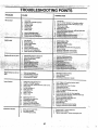
PROBLEM
CAUSE
CORRECTION
Will not start
1
Fill fuel tank
2
See_O START ENGINE"in Operation section,
3
Wait several minutes before attempting to start.
4. Replace spark plugo
5. Clean/replace air filter,
6, ';Re_lace _ el ftlte'r.,
'
,
,
,
_
7, _D_._n'fue!'lafil_
&rid carburetor,refill tank Withfresh
"2, ' _Rep!_cesiaB,plug,
a!
,,
4o : _eplace J_elfiltar_ " '
S,:
,. :.
Re0_aigdoi:'i-_pl_ico
ba'ttery.
J_rain fu_l iar_aitd
-
,
':"
r,;S[
'-
'
':'.
refill wilh fresh ga§ofine
/' :.'
6_. Ch_qk'allwlrlng,:'
;'" "
7, ' Contactan a_Jthorlzed
service facility,
8. Cor;,ta_,ia'h _Lith01:tzed
service faci)tty_
•
, Engine will not turn over
I
Clutch/brake
,pigd_.not depressed.
,;
'. 'i:_.'',
'_.
• 2, Attachmentclutchlsengaged..
_:_ .....":
:
_:,
.' 3.
Weakoi;;deadbaflery.
.
.
.;}__ ", ! i
" ....
4 : Blown fuse;, .:.::";., :._ ._:
, .
•_:::, .,-'-_',•_.,
_-•: =,.5 -.,Corrodedb_ittalytem'|lnals,, .: .......
,
: 2o' _Dlsengaga attachment clutch,
,_. .... : ,3,. 'Recharge _rie_!a'ee battery
.:: ." _ :'
. :-,, _ % ;::_,.,,401aati_,i_l!_;6[_tnais.:
, ?,,,[,
";'i"_
;'_'
:_1;
.::i
:.:i:
,
_
-
,............
, ...... • ......
:,Engll_cllcke
but w!ll not
start
,.;,:.:::,
';.7;,,:;_:_liei__ei_lacla
{_nlllon sw tch;."_<
....
:.'..,
8, .FbultySolanoldorstailah! ..............
,.._.... ,, .. ,.:B;:._/_.ftecklrepface:eblenoJ_or.sta'rter;.c..::,
;
.' .:,..., .:;-Y:,':_,
.au,._o_.era_r_.resencesw,...,e_ .....
., ,..:,
:.9:%_n_ct an'au_fi_itzedserviceI_actlRy, tt,.,
. , , r
'1
,,
.........
._., :.,:,..-; ....
.......
1,
2,
Weak or dead 6_ttery,. = ,
Corroded balled/terminals,
3: Looseor damagedwldng,
4= Faultysolenoid or starlero
1o
2,
3,
4,
Racha'rge or replace battery,
Clean battery te'rmtnafs,
Check all widng
Check/replace solenoid or starter,
'":
'1
r_
":
_'1'"
_t
'
'1:_'_
':_"
i......
Loss of power
1,
Cuttingtoo muchgrass/leofast.
t,,
Set In "Higher Cur' positionfraduce
speed,,
2,
3,
Throttle iB "CHOKE" position.
Build-up of grass, leaves and trash under mower°
2,
3
Adjust throttle control,
Clean underside Of mower housing,
4_ Dirtyair lifter,
4,
Clean/replaceair filter
5,
5,
Check otl level/change oil
6
7,
Cleanand regap or changesparkplug,
Replacefuel_lter,
Low oil level/dirty oilo
6o Faultysparkplug,
7,,
8,
9,
:
.......
Dirty fuel filter.,
Stale or dirly rue!,
Water in fuel,
8. Drain fuel tank and refill with fresh gasoline,
9_ Dreln fuel tank and carburetor, refill tank with f"resh
!0.
10o
Spark plug wtre loose.
11.
Dirtyengine'alr screen/fins,
12.
13,
14.
D!rtylclogged muffler,,
Loose or damaged widng,
Carburetor out of adjustment,
15,
Engine valves out Of adjustment,,
12,
gasoline' and
Connect arid
Clean englne
Clean/replace
repJaca rue! (liter,
tighten' spark plug wire,
air screen/fins,,
muffler,
Ch_ck_='w!_ng,
14. Contact an authorized service facility.
15,,
, .
C0ritact an authorized service facility,
'
L__,
Excesslve vibration
1,
2,
3,
Worn, bent or loose blade,
Bent blade mandrel
1, Repiace blacle, Tighten blade bolt,,
2_ Replace blade mandrel.
3, Tighten loose part(s), Replace damaged parts,
.
Loose/damaged part(s),,
27
. .
J
OOTING POINTS
TRO
..............
7,
.. .
. i,
" :,--..- ..:
: _
..
.....................
PROBLEM
CAUSE
CORRECTION
Enginecontinuesto run
when operator leavesseat
with attachmentclutch
engaged
1.
Faultyoperator-safety
presencecdritrolsystem
1_ Check wiring,switches andconnections,if not
corrected,contactan authorized servicefe,c,tty_
Won1, bent or loose blade.
I,
2_
3,
''
Mower
!5,:
!,
2,
3,
4_
.1.
Englhespeed tooslow,
"I
2.
3.
2. Travel,speed.toofast,
3 Wet grass.
4, Mowerdecknotlevel,
5. Lowtunsventirea1_pressure.
b, Worn,bent or Ioo_e blade,
,11
,111111iii
Replace b[ade_ Tighten blade boil,
Level mower deck.
Clean undersl_e o_ mower housing,
Clean_.tO_Jhd'rnE_'_dre!s
to Openventhoi_so
Removeobstruction.
Replae_mower bidvebelt,
F,_eptace
idlerpulley.
Replacebtademandrel
P.tace thro_'e _orltrol in "FAST". position
Shift to siower, spee d.
Allow grass to dry before mowing
4. Levelmowerdsck.
5 Checkt!reefor properair pressure,
6, Replacs/sha_enblade, Tightenblade bolt
7, Clean u
mowerhousing
7.
belt
Batterywill not charge
1. Switchis"OFF",
Bulb(e) burnedout.
Faultylightswitch,
4 Looseor damagedwidng.
5, Blownfuse',
_o Turnev_tch"ON",
_.. Badb_ttery
ce,(s).
_, ReplacebatterY.
2. Checlffcteanall connections,
3. Replaceregulator,
4, Replacealternator,
2,
3,
4,
Engine "backfires"
when turning engine
2,
3
4.
5,
Poor cable cgnnections;o
Faulty regulator (if so equipped),
Faulty alternator,
1
1,. Enginethrottlecontrolnot set at'SLOW" ,
positionfor 30 secondsbefqmStoppingengine.
"OFF", '
,.
r,
3
I
?
/
28
Replace bulb(s)_
Check/replace light switch
CheckWtrtng andconnections_
Replace fuse
Move throttle control to "SLOW' position and allow
to idte for 30 seconds before stopping engine,
RED
BLACK
BATTERY
RED
S
IGNITION SWITCH
I
!
AFTER FIRE SOLENOID
cHARGING SYSTEM OUTPlJT
3 AMP DO @ B800RPM
2BV()LTS AC MIN, @ 3600 RPM
(CHARGING SYSTEM DISCONNECTED)
t
UGHTING
SYSTEM
I
"_
.I
..........
t
I
NOTE
OUTPUT
_E
;i ALTERNATOR
Ii
5 AMP
AC g' ,3600 RPM
F'_
......
',_
....
i '
YOUR TRACTOR IS
_
_.,n,,..j-_
_,
EQUIPPED WITH A SPECIAL
ALTERNATOR SYSTEM '
THE LIGHTS ARE NOT
i_...
:ii _EADLIGHTS
CONNECTED TOTHE
•
. | i" .....
, . .i"
'i:!';_, /-_-_...
BATTERY, BUTHAVE THEIR _.
_B__
i
OWN,ELECTRICAL SOURCE.
;v_ _-___.I
_ "-_/.i_'
T'-"
"
BECAUSEOFTHIS,
THE_.:, ' HEA-DUGHT
\
1_:_
I
BRIGHTNESS OF-THE LIGHTS
' SWITCH
._-(6
IGNITION SWITCH
WILL CHANGE WiTH ENGINE ..
:(OEE3..
. '
.. " _
'
' SPEED,::':AT,tDLE:THE'UGHTS _;_ :_ ',:_
:,:'
_:,"_i:_:
,:":"';,' ' ':: _ ..
,
WILL DIM. AS THE ENGINE" IS
::
WiBING INsI_ILATED cLiPB
'
"
SPEEDED UP, THE LIGHTS "
WILL BECOME THEIR BRIGHTEST. ' NOTE: IF WIRING INSULATED
/_
' .
CLIPS WERE .REMOVED FOR
SERVICING OF UNIT, THEY
SHOULD BE REPLACED TO.
---_--NON-REMOVABLE
_
REMOVABLE
PROPERLY SECURE YOUR WIRING.
CONNECTIONS
CONNECTIONS
I_
II
•
:29
", ,,,,o<,_
,,o,,,,,;;<_;;<C,o;_;<_
....
-'
i •
r._
TRACTOR-L
,
,
MODEL NUMBER 917,256522
......
_: ELECTRICAL
22
21
f
l
i
70
!
I
I
I
I
I
I
I
I
41
26
I
I
2O
i
I
I
!
I
I
|
I
!
|
I
I
J
I
€[
1
t
t
I
I
i l
\
I
/1
1
/
29
f
52
\
\
\
I
I
I
I
I
I
I
I
I
I
I
I
I
:
I
i
\
_, 30
M
....
'TRACTOR - - MODEL N MBER
_: ,_ _ : ';'"_ _'_,7':_I _,,','_' _-_,', ¢ ,;_': "i',:_,,_', _1
h
917.256522
'. ,:_
ELECTRICAL
KEY
NO..
PART
NO.
• 1:146139
_, 2. ',74760412 .
' ..'. : .- 3.-_8T055,1025
.
..
. ÷,'L
DESCRIPTION
Battery !2 Volt 25:Amp
,Bolt, HexHead '1/4-2Ounc x 3/4,
:Washer: ..... :",' ' : "'* "" : ':"
' '
, ,
'
"
"
r:'
....
i::'7.:.":.:!09236X' ' ; _ube; Plastic, 12" ,:'
.
: : ' i, .;!,....._
' 8 _-144940 "
CaUse,Battery W/2 Holes W/Brty
"
:
_. '-9 109596X
Clamp, H0se'., :' ' '_t5 147688 " " FasteS_er.Snal__'ln . ,
-: 18 ,. 153664
Switch lllterlock'Push-in
.
.
19 STD551125
20 73350400-
_
i_,:,_"
"_":'*
_::
.' .i
4152J
4799J:
24
25 1 6,147
26
j"
38
39
40
41
42
43
44
45
52
70
140336 .: _"
109553X
151212
71110406
131563
'I45673
73640400
121433X
141940
141164
NOTE:
Bracket; Interioct_Switch ' '": ...... ,_
Switch, Interlock, Clutch, 4'Terminal '
Harness, Ignition - "
Bolt, Hex Head,,Fin, 1/4:20 x 1/2
Cover, Terminal, Red
Solenoid
Nut Keps Blk Hex" I/4-20 UNC
Ammeter Rectangular 6 Amp
Protection Wire Loop
Harness Engine B&S P/L 14 OHV Du HI
All component dimensions given in U,S, inches '
1 inch = 25.4 mm
t_
'31
'_*
TRACTOR -- MODEL NUMBER 917.256522
CHASSIS AND ENCLOSURES
*
29
26
57
i
40
€
33
10
34
26
32
i
TRACTOR -- MODEL NUMBER 917.256522
CHASSIS AND ENCLOSURES
• "12r,
';!45660. ;:
Cl_pTinnetman Grille P/L
" _13 146962,
PaneJ,_DaSh,R.H. " ' " ,i
•.14 17490608
SbrewThdml,3/8-16 x 1/2
. "15 '74180512
scmW;'Machine, Truss Head
"' ' :_: "
. 5/16.:18 UNCx 3/4
'
16 STD541431
Nut
:....
:
17
Hood A§semb]y •
'
BOlt'.. , """":
'
' "
34
35
38
39
40
51
52
53
54
55
57
58
60
74
140
_-
145243X574
8TD533707
139886
139887
139977
7380040O
19091416
145201
17030814
145202
STD522507
15O127
72140606
73680600
150556
54793
. .:
"
:
•
:
R,H,
B0tt '; ' '
Pivot Bracket Assembly, L.H.
Pivot Bracket Assembly, R.H.
Spacer Fender Raised LT
Nut Lock w/Insert 1/4-20 UNC
Washer 9/32 x 7/8 x 16 Ga_
Bracket Grille Pickoff LH
Screw Splder!ock Hex Hd #6-7/8
Bracket Grille Pickoff RH
Bolt, Fin Hex 1/4-20 UNC x .75
Air Duct PiL Engine
Bolt Rdhd Sqnk 3/8-16 UNC x 3/4
Nut Crown!ock 3/8-16 UNC
Bracket Chassis Front
Plug, Button
NOTE: All component dimensions given in U.S. inches
! inch = 25.4 mm
33
r._
:
_ 42
55
35
• 37
34
26
27
22
34
'
iL
__
"_
"
:
_I
_'i '_
i _,_
DRIVE
2_ 106933X
22:130804
24 STD541237
25 106888X
26 STD551037
27 STD561210
Knob
Rod, Brake
NUt
ring, Brake Rod
sher
Pin " : _ :'
65
66
70
.. 72
STD551143
153400
134683
19132012
109502X
Washer
Keeper, Belt, Engine, L.H.
Guide, Mower Drive Belt, R_Ho
Washer 13/32 x 1-1/4 x 12 Gauge
x 1-1/4 x 16 Gau
:36 , STD551062
37 STD57i810
3s t2387_,x
39
40
4"1
42
44
45
46
47
STD523727
4470J
153399
19131312
105706X
.110812X
12000039
127783
82
83
t23782X
19171216
84 _32183
85 150360
86 71208
87 19212016
88 12000008
89 139964
90 124346>(
110 74760612
116 72110610
earing, NylOn
Washer
R011Pin
Pulley, Idler, Flat
Bolt
Spacer, Split .395 x °59
Keeper, Belt, Retainer
Washer !3/32 x13/16 x 12 Gauge
Bearing, Nylon
Washer, Hardened
Ring, Klip
Pulley, Idler, V-Groove, Plastic
• .,,Shaft Assembly
............ '
..
Spdng; Torsion
Washer 17/32 x 3/4 x 16 G_uge
Tie Rod
Nut, LockCenter 1/4-28 Fnthd
Bushing, Pivot
Washer
E-Ring
Console, Shift, 6 Speed, N/Ignition
Nut, Self-Threading, Washer Hd 1/4
Bolt, Fin Hex 3/8_16 UNC x 3/4
Bolt Rdhd Sqnk 3/8-16 x 1-1/4
NOTE: All component dimensionsgiven
1 inch = 25.4 mm
35
r•
in U.So inches
_:!:
_
TRACTOR -- MODEL NUMBER 917.256522
STEERING
ASSEMBLY
r
8
27.
16
:i
36
32
.
STEERING
ASSEMBLY
KEY
NO.
'7
PART
NO
DESCRIPTION
:!
8 12000029
•9 3366R
10 i'30468
11 STD551137
12 736!0600
13 1!0;4_38X: ,,
t4 740t1056
15 ;73901000
16 !3J262_ " =
. 17 440176
18 57079.
.19 '".12.4035X
20': 126684X
_-,
21 i:
1i4906_12
3(_ STD561210
32 130465
36 132196
37 152927
38 139769
39
'19133808
41
42
43
100711L
145054
t21749X
44
153720
.46
47
•61
_54
62.
63
121232X
6855M.
STD541431
74780,520
t49686 '_
74780616 '
x718:X 16 Gauge .:,
Screw, Thd, Roll 3/8.-16X 3/4"
Pin
Rod, Tie ,
Bushing, Steering
Screw
Insert, Steering Wheel
Washer 13/32 x 2-3/8 x 8 Gauge
Adaptor, Steering Wheel
Boot, Steering Shaft
Washer 25/32 x 1-1/4 x 16 Gauge
Extension Shaft Steering NonAdjust
Cap, Spindle
Fitting, Grease
Nut Lock Hex w/Ins. 5/16-18 UNC
Bolt Fin Hex 5/16-18 UNC x 1-1/4 ;..,
Kit Steering Asm Service
"
::
Bolt, Fin Hex 3/846 UNC x 1 Gr; 5
••
1:1'{
, -I',/_
NOTE: Aii componer_t _limenstons given in U.& inches
! '
1 inch = 25.4 mrn
'
• t
37
<
:_t_'•
,:•
i: ¸ ,
.
,
• •
:It"
......
_ii_,_,
REPAIR PARTS
:_:i
'_: '
;
....
_,h_,_r_
_*.,_
__
'.'W _+; I;_I _' _¸ '_)_
_
_....
" _"% _, ;':"
.....
TRACTOR - ' MODEL NUMBER 917.256522
SEAT ASSEMBLY
....
k
........
'!_:_ili
¸:
_ill
¸_'
23
12
KEY
NO,
PART
NO.
1
2
3
.4
5
'6
7
I}
9
10
12
13
14
140123
14055.1
STD523710
19131610
145006
STD541437
124181X
"i74_o616
19131614
140552
121246X
121248X
72050411
KEY
NO.
DESCRIPTION
5 _3,_o0
Seat
Bracket, Pivot, seat
Bolt
Washer 13/32 x 1 x 10 Gauge
Clip, Push-In Hinged
' Nut
Spring, Seat
_¢r_w,
Thd,
Roll,
9/B-16
PART
NO.
16
t7
21
22
23
24
x I
25
26
Washer 13/32 x I x 14 Gauge
Pan, Seat
Bracket, Switch Mounting
Bushing, Snap
Bo_t,Carriage 1/4-20 x 1-3/8
121250X
123976X
153236.
STD541431
74780814
; 19171912
127018X
STD551150
DESCRIPTION
Spacer', Split ,28 x ,86
Spring - '
"'
Locknut,Flange 1/4 Grade 5
Bolt, Shoulder 5/!6-18 UNC-2A
Nut
Bolt, Hex Head, Fin_
;1/2_13'X7/8 Grade 5
. .,.__:;
Washer 17t32x 1-3/16 x 12 Gauge
Bolt, Shoulder 5/16-18 X ,62
Wasl_er, Lock
NOTE: All component dimensions given in U.S. Inches
1 inch = 25.4 mm
s8
DECALS
13
2
6
3
18
7
7
18
10
4
2O
14
Decal
Decal
Decal,
Decal,
Decal,
Decal,
Decal,
Decal,
Decal,
Decal,
3 15O683
4 150684
6 133644
7 150927
8
150955
9 128314
10 137537
11 4900J
12 146046
WHEELS
R,Ho
Hood, L.H. _
CustomerMa_ntenance
Side Panel :"
Deck Mower EZ3 Dover
Fender, Craftsman
Caution, English
"
Clutch!Brake, English
V,Belt Drive Schematic
,.14_136832
15 145245
17 133179
18 150685
20 149516
.-,145247
*- 138311
-154114
-154115
& TIRES
KEY
NO.
1
2
3
4
5,8
F"-.
"_ /
4,10
5
6
7
8
9
10
PART
NO:
'
_est Rbr
Craftsman
Pad
Decal, Mower QC System
Dec&l, Ins. Hood
Decal Battery Dngr/Psn Eng
Fastener Pop tn Footrest
Decal, Lift Hahdle
Owner's Manual, English
Owner's Manual, Spanish
DESCRIPTION
Valve Cap, Tire
stem,, valve
:
Tire, Front
.
Tube, Front Tire
.
(Not Provided, Service Item Only)
Rim, Front
': . .
106732X427
278H"
:._ Fitting,Gi'ease (Front Wheel Only)
59192 "
65139
106222X
59904
; 9040H
Be_ring
Ptar_ge (Fr0ht Wheel Only)
106108X427 'Rim,.Rear
122082X
Tire, Rear
.
7152J
Tube,. Rear Tire
;
(l_0t Provided, Service Item Only)
11 :104757X
Cap, Axle
, . .._'_':i_.
- - 144334
Sealant, Tire 10 oz::
:
NOTE: All Componentdimensions given in u.s. incl;ies
_1inch=25.4mm_'
7
. . •
39
-'.,
TRACTOR -, MODEL NUMBER 917.256522
13
4'
-
33
37
18
33
40
23
22
29
OPTIONAL EQUIPMENT
Spark Arrester
40
'
KEY
NO.
ii!:!/
PART
NO.
,1 150600
2 17720410
DESCRIPTION
C_
Cutting
En
:i,0173-01.
: ,?.,
",
Gasket,:Exhaust
Nipple; Plp,e 3/8 NPT x 3
'Elbow, Standard 90 °, 3/8-18 NPT
Washer
•,Shield, Heat
: ReCeptacle; 1/4Turn
Stud, 1/4 TurnW/Bushlng Plst
Shield, Heat
Arrestor, Spark
Pinch Weld_ Hood
Tank, Fue!
) Assembly, Fuel Tank, Vented
3i4
46
62
72
78
81
19091416
STD55113t
71070512
17490620
'128861
Washer 9/32 X 7/8 x 16 Gauge
Washer, Lock
Screw, Hex Cap Head 5/16-18 x 3/4
Screw, Thd., Roll. 3/8-16 x 1-1/4
Nut Flange 1/4-20 Starter Nut
NOTE; Ai! component dimensions given in U.S. inches
1 inch = 25.4 mm
JJ
]
t_.if
13 272293
14 13280324
15 13200300
16 STD551237
18 136718
19 105839X
22 149793
23 150554
29' 137180
30 127057X
31 109202X
32 123549X
33 123487X
L
TRACTOR -- MODEL NUMBER 917.256522
.owsRU_
28
27
26
23
r,.
7
49
5
3O
6
5
13
19
2O
15
31
32
f
E Ek
42
I
TRACTOR - - MODEL NUMBER 917,256522
MOWER
LiFT
KEY
NO.
27 !!126971X "_'
28 73350600
29 138057
30 150233 ,
31 140302
' 32 73540600
49 145212
Adjustment
p
Bearin_g,Pvt;
Nut, Crownlock
Nut Hex Flange Lock
NOTE: All component dimensions given in UoS. inches
1 Inch = 25.4 mm
43
L
- MODEL NUMBER 917.256522
68
105
43
102
33
106
++
';/
116
113 111
114
21
22
24
\
2
26
28
29
18
r
IS
44
114_
_121
27
TRACTOR - - MODEL NUMBER 917.256522
MOWER
KEY
NO.
DECK
PART
:NO.
i,;"
29
30
31
32
33
34
35
36
37
40
4i
43
44
45
46
48
49
50
51
52
53
131491
138776
129963
153535
'137266
STD533717
133835
131494
19131316
STD541437
133551
1400B3
140088
STD624003
-137729
133944
13394O
131.340
STD5414i0
139888'
131845
KEY
NO.
DESCRIPTION
PART
NO.
DESCRIPTION
" •
Rod, Hinge.
"
Screw Thdrol Hex Head Zinc Mwr
Washer, Spacer
Pulley, Mandrel
Nut, Toploc k, F!anged
Bolt
Fastner, Christmas Tree
Pulley, Idler, Flat
Washer 13/32 x 13/16 x 16 Gauge
Nut Crownlock 3/8_16 UNC
Rod, Pivot, with Nibs
Rod, Clutch, Secohdary, with Nibs'
Guard, Mandrel, L.Ho
Retainer
'
Screw, Thd. Roll 1/4-20 x 5/8
Washer, Hardened
Roller Assembly, Cam Follower
Bolt, Shoulder #.10-24 Grade 5
Locknut .•
.Bolt, Shoulder 5/16-18 UNC
Arm Assembly, pad, Brake
106
111
112
113
114
115
116
117
118
119
121
128
---
2029J
140353
132262
17490512
73510500
72110504
137644
133957
73930600
19121414
143723
153390
130794
!4541i
Nut, Weld Bracket, Gauge, wheel L.H.
Bracket,Gauge, Wheel R,H.
Screw Thdrol 5/16-18 x 3/4
Nut, Hex, Keps 5/16_18 UNC
Bolt, Carriage 5/16 UNC x 1/2
Bolt, Shoutder
Wheel, Gauge
Nut, Centertock 3/8-16
Washer 3/8 x 7/8 x !4 Gauge
Bracket
Washer Feli
Mandrel Assembly (Includes Key
Numbers. 8-10, 12-15, 31 and 32)
MowerDeck, Complete (Standard
Deck, Order Separately Mulcher
Plate a.nd Gauge Wheel .
. .:
Componentsl Key Nos. 101-106
and 111-12!)
NQTE::
.Ati.component
dimensions
.... ;::.: .!1
inch = 25.4 trim'..".
: ."" given
, in
' u.s," inches
45
!!i!/, DANA TRANSAXLE-
_!(: ,
MODEL NUMBER 4360-97
"
21
24
36
35
11,=,
/
39
/
44
46
55
6
12
47
48
57
/
59
49
50
55
19
,0
62
63
59
65
67
8
_'_
:
_:! :
:
'
DANA TRANSAXLE
35
36
37
38
105925X
2232J
108978X
t10079X
TRACTOR.
- MODEL NUMBER 917.256522
- MODEL NUMBER 4360-97
Washer Plain .640 X 1o37 x .061
Washer Plain .632 x 1.00 x .026
Spacer .630 x 1.00 x .169
Assembly, Gear, Combination,
12 Teeth and 35 Teeth
73
120416X
Grease
NOTE: All component dimensions given in U.So inches
t inch = 25.4 mm
oI!,
i__.
!;_l_ii!_!_=_
.....
REPAIR PARTS
;
_0_ _
':_
TRACTOR
BRIGGS & STRATTON
-- MODEL
NUMBER
ENGINE - MODEL NUMBER
3
28N707,
917,256522
TYPE NUMBER
i
0173-01
230
552
' 614
@
634A
_'
718
635
337
1022
40
868A
868
1034
1026
45
++-,+++ • :_r
_+ _,_,:;+,,_+r_,_,:+,++
:_++_'_;++_:_'+_:;+,_++_,_;i_
_,_"
_';:r:l++
;_+_+'++
:
_'_i_;i+,
¸ +"
L'_!
"_:q:'_:'
_!!_?,:,
_+REPAIRPARTS
;i::!,
+/
" "'_
"
'
_'"
"_1¸_+¸
"+_'"_
+_'_'+'_ '+h:_ _','_'_:_,_
+=
TRACTOR - - MODEL NUMBER 917.256522
BRiGGS & STRATTON
127
+:+_+_+>_'_?:?
138
106
ENGINE-
MODEL NUMBER 28N707, TYPE NUMBER
987
0
!16
21CARBURETOROVERHAUL
r'
i 1 _;+
• :'' +'• : + ,
,+
++I
"%_
123
"k REQUIRES SPECIAL TOOLS
TO INSTALL SEE REPAIR
INSTRUCTION MANUAL.
KIT :
0173.01
_+; _+ +_"
REPAIR PARTS
:
TRACTOR
BRIGGS & STRATTON
; .....
++r:., +...... ......,. +
-- MODEL NUMBER
917.256522
ENGINE - MODEL NUMBER 28N707, TYPE NUMBER
3
523
20
634A
842
524
868
0173-01
467
537
9
52
363
_524
445
%
'
977 CARBU!
304
1044
+
468
1006
4"
_8
50
TRACTOR , - MODEL NUMBER 917.256522
BRiGGS
& STRATTON
ENGINE - MODEL NUMBER
28N707,
TYPE NUMBER
0173-01
232
216
201
]
265
601
t
801
728
1090
311
803
•
r
544
51¸
KEY PART
NO. NO,
DESCRIPTION
95 94098
98 495800
104 231789
** Screw, Throttle
Screw, Idle Speed
** Pin, Float Hinge
** Valve .Float
;.** seat, Inlet Valve
Valve; ;Ch'oke,,?:
-.
** Jet, NG'edle Valve
Valve; Needle
'
Carburetor Overhaul Kit
Screw, Elbow Mounting
Carburel_0rAssembly
** Plug, Welch (Sold in Kit Only)
Valye, Throttle
Shaft and Lever, Throttle
Float, Carburetor
"** Gasket, Float Bowl
**** Washer, B0wl
Shaft and Lever', Choke
** Nozzle, Carburetor
** Pilot, Jet
Elbow, Carburetor
Stud; Rocker Arm
Nut
hung
!, Cut to Suiti
lO5 23 855
t06:23_854
117_:23!858
118 495932
121 _98116
123 94616.
125.498051
127.:;_:-',,."
130 224539
1_1 49.4,379
133 494381
137 281165
138 281164
141 495931
142 231859
147 497472
164 214047
* Gasket, Crankcase Cover, .009"
Screw, Cylinder Head
Plug, Oil Drain
.Crankshaft
Timing Gear Key
. Base, Engine
* Seal, Oil
Screw, Seres, Base Mounting
eel and Ring Gear Assembly,
ize
"J"
;_'
_i';_
27
28
"_'
29
/'" _":
495855
260924
299691
391286
494504
495490
ii: a2 94695
:
_'i
i!:':
_;'
;,
i"i_
":_,:'
32A
33
34
35
37
40
45
46
51
75
i
:Ta
94648
495856
495857
262811
224502
224641
262411
496884
272465
224061
e4o_
Piston
Rin
Rin
Rin !Set, Piston, .020" Oversize
Rin Set, Piston, ,030" Oversize _
Piston Pin
Pin Assy. Piston, Star!dard Size
Pin Assy., Piston, .005' OverSize
Rod Assembly, Connecting
Rod Assembly, Connecting,
.020" Undersize Crankpin Bore
Screw, Hex Washer Head, 1-57/64
Screw, Hex Washer Head, 1-5/6
Valve, Exhaust
Valve, Intake
Spring, Valve
Guard, Flywheel
Retainer, Valve Spring
Tappet, Valve
Gear, Cam .
**** Gasket, Carburetor (Carburetor' to
Elbow) (Also Included in Gasket
Set, Part 'Number 495993)
*** Gasket, Ca.rburetor
(Elbow to Cylinder)
Stud, Carburetor Mounting
Washer', Spring _
Oorow,
Pon
'Rocker Arm
209
216
219
222
224
225
227
230
232
238
240
265
284
*
*;
"i:
262766
490815
495611
94729
495157
493935
94742
262785
262836
394358
221535
947O4
i
o0_erh0r '
spdr
Link,
Gear, Governor
Plate, Governor Control
Screw, Sems, Air Cleaner
Crank, Governor
Lever Assembly, Governor
Washer, Governor Crank
Spring, Governor Link
Cap, Valve
Filter, Fuel (In Fuel Line)
Clamp, Casing
Screw, Hex Head
Included in Gasket Set (495993)
Included in Carburetor' Ki! (497535)
***
included in both Gasket Set (495993) and
Valve Overhaul Kit (495992)
****
InciLIcled in Gasket Set (495993), Carburetor Kit
(497535.) and Carbui'etor Gasket Set (494385)
NOTE:All cbmp0n;e_itdimeiis[ons g!ve'n in U.S. inches
1 inuh = 2,5.4 mm
Ile_d
.....
J
' 5
52
_
TRACTOR -- MODEL NUMBER 917.256522
t_RIGGS & STRATTON
KEY PART
NO, NO,
284A 94073
294 810068
304 496280
,-305 94786
:.;:.':,::. ';_'_::.:i./
':3d6 225,020
':3'07i_9_B6:
_3'09. _97_;95.
310 _:_97602
.311 497608
.333 495859
,334 93381
337 491055
..:_6. 93705.
_356' 497708
.358 495993
31_3 19203
•383 - 89838
423 94073
.445 493909
ENGINE-MODEL
NUMBER 28N;t07, TYPE NUMBER
DESCRIPTION
Screw, Hex Head
Screw, Set
Housing, Blower
Screw, Hex, Head,
Blower.HousingMounting
..
"Shield,lcyt nder ,:_.'... "
. :i'". Se.:te_, _-_'linder.Shleld
' ; Mot6r; Staitei_:
' "
•
.Bolt',Thru '
Brush Set
Armature, Magneto
Screw, Sems, Armature Mounting
Plug, Spark
Screw, Hex Head
Wire Assembly
Gasket Set
Puller, Flywheel
Wrench,Spark" Plug
Screw, Sems
Cartridge, Air Cleaner
O173'0i
KEY PART
, NO, NO,
'
DESCRPTION
729A 225170
741 262932
757 21399B
758 399891
759: 298_09,.,
'7.61: 94_593::i ;;: i
",,783" 280i04_. :: ._
Retainer
Geal', :]
Link, C
G0U'nt_
Pin:'C_
Sqrew_:
Geari_i_
Bol '
802:_,:49_605 "'
803 .497604
842 : 270920
847 ;496415
851 224110
868 49.4435
868A 2726'i0
871 262835
872 =281361
875 495B62
B77 393A56
•947 497157
Wire
ning
Jntea Bight.:_
v_Igl ASsembly .
ntei_
' cai i;:=5
Cap,.E
Hoiisin Sta Ier
* Seat,:€ ,Filler Capl : ,:""
FBIGr(: p,'Oil
'
'
Terrnina, IgnffionCable
*** Seal Asi ;embty, valve
*** Gasket Vat_ie
'!' :"
Bushing, GUide (Intake & Exhaust)
Co'¢er, AlrCieaner
:. : "
Bociy,;Aii"Cle_iner :_.: : :
Diode and Cdrinector As,sembly
Solen6_d, "
bly, Carburetor
_asket.Set '
535 272403
537 281106
544 497603
552 231597
562 92613
592 231082
601 93053
611 493496
614 93306
618 262803
634 281168
634A 491323
634B 281167
635 280872
646 -224546
657 93496 _
663 94620
668 280848
718 230192
726 _ 392134
727 490324
728• 94627
729 281390
Element, Filter
* O-Ring,_AirCleaner
Armature, Starter
Bushing, Govemor Crank
Bott, Carriage
Nut, Hex
Clamp, Fuel Pipe
Elbow, Fuel Pipe
Pin, Cotter
Spring, Choke Return
** Seal, Choke Shaft
*Seal, Governor
** Washer, Throttle Shaft
Boot, Spark Plug
Brace, Air Cleaner
Screw, Sems
Screw, Self-Tapping
Spacer
Pin, Dowel
Gear, Ring
(Includes Mounting Hardware)
Cover, Starter
Screw, Hex Head
Clip, Wire
1029
1033
1034
1044
1054
105B
1090
495136
224554
495992
495248
94673
270723
272623
497607
RPM Settings:
er Arm :
ntake
Rod, Push Exhaust
Arm, Rocker
Valve Overhaul Kit
Guide Assembly_ Push Rod
Screw, Hex Head
Tie, Cable
Manual, Owner's
Retainer, Brush
Low: 1650_1850, High." 3200-3400
included in Gasket Set(495993 )
included in Carburetor Kii (497535)
Included in both Gasket Set (495993i and
Valve Overhaul Kit (495992)
****
Included in Gasket Set (495993)i Carburetor Kit
(497535) and Carburetor Gasket Set (494385)
NOTE: All component dimensions given in U_S. troches _....
1 inch = 25.4 mm _
":_
,53 •
_,,,,,,_,
54
.
' Ill t' It'!
I'1
SUGGESTED
GUIDE FOR SIGHTING
SLOPES
ONLY RIDE UP AND DOWN HILL,
NOT ACROSS HILL
SIGHTING
GUIDE
O1
01
FOR SAFE OPERATION
SIGHT AND HOLD THIS
SKY LINE OR TREE.
LEVEL
WITH
!
15° MAX.
Operate your Tractor up and down the face of slopes (not
greater than 15°), never across the face. Make turns gradually to prevent tipping or loss of control. Exercise extreme
caution when changing direction on slopes.
•,=
IIIIIIIIIIIIII
CRAFTSMAN+
OWNER'S
MA
AL
15.5 HP IC
ELECTRIC START
42" MOWER
6 SPEED TRANSAXLE
LAWN TRACTOR
MODEL NO,
917.256522
Each tractor has its own model number'_ Each engine has
its own model number.
The model number for your tractor wi]l be found on the
model plate located under the seal
The model number for your engine will be found on the
blower housing of the engine.
All parts listed herein may be ordered from any Sears,
Roebuck and Co. Service Center/Department and most Retail Stores,.
IF YOU NEED
REPAIR SERVICE
OR PARTS:
WHEN ORDERING REPAIR PARTS, ALWAYS GIVE THE
FOLLOWING INFORMATION:
FOR REPAIR SERVICE, CALL
THIS TOLL FREE NUMBER:
. PRODUCT- TRACTOR
1-800-4-REPAIR
° MODEL NUMBER - 917.256522
(1-800-473-7247)
• ENGINE MODEL NO. - 28N707, TYPE NO. 0173-01
° PART NUMBER
FOR REPLACEMENT PARTS
INFORMATION AND
ORDERING, CALL THIS
TOLL FREE NUMBER:
° PART DESCRIPTION
Your Sears merchandise has added value when you
consider Sears has service units nationwide staffed with
Sears trained technicians.,
professional
technicians
specifically trained to insure that we meet our pledge to
you, we service what we sell.
1-800-FON-PART
(1-800-366-7278)
FOR CONSUMER ASSISTANCE
HOT LINE, CALL THIS
TOLL FREE NUMBER:
1-800-659-5917
154114
Rev. 1
2_28.96
JH/KFSW
..............................
II'
tI"_t_
r= ,,
Printed in US.A.