1
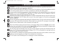
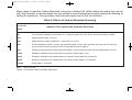
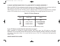
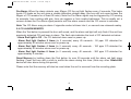
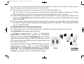
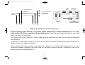
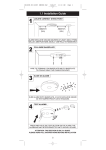
B16587-R0-262-UC-ENG
15/4/09
3:38 PM
Page 1
RadioLINK
MAINS POWERED
CARBON MONOXIDE ALARM
WITH RECHARGEABLE LITHIUM CELL BACK-UP
The RadioLINK Carbon Monoxide Alarm Ei262 will
communicate with all other RadioLINK devices including
Smoke/Heat/Fire Alarms, Relays and other accessories.
Model Ei262
Read and retain carefully for as long as the product is being used. Contains vital information on the
operation and installation. This leaflet should be regarded as part of the product.
If you are just installing the unit, this leaflet must be given to the householder. This leaflet is to be
given to any subsequent user.
B16587-R0-262-UC-ENG
15/4/09
3:38 PM
Page 2
CONTENTS
Page
1
IMPORTANT INFORMATION
3
4
What to do when you alarm is activated
2
CARBON MONOXIDE - THE SILENT KILLER
5
3
ALARM POSITIONING
9
4
INSTALLATION
13
13
17
20
4.1 Mounting & Wiring Alarms
4.2 RadioLINK Interconnecting etc.
4.3 Hardwired Interconnect
5
USING & TESTING YOUR SYSTEM
22
6
HOW TO DISTINGUISH BETWEEN CO ALARM & SMOKE ALARM WARNINGS
24
7
MAINTENANCE
24
8
LIMITATIONS OF CO ALARMS
26
9
HOW TO PROTECT YOUR FAMILY
28
10
GETTING YOUR CO ALARM SERVICED
30
11
FIVE YEAR GUARANTEE
30
12
TECHNICAL SPECIFICATIONS
31
13
ACCESSORIES
34
14
TROUBLESHOOTING
36
2
B16587-R0-262-UC-ENG
15/4/09
3:38 PM
Page 3
1. IMPORTANT INFORMATION
?
WARNING: The Alarm should be permanently wired to the mains by a qualified electrician in
accordance with IEE wiring regulations (BS7671).
Install a Carbon Monoxide (CO) Alarm in every room that contains a fuel burning appliance, and in
rooms where people spend a lot of time e.g. bedrooms, kitchens and sitting rooms.
In rooms with an fuel burning appliance, install (preferably) on the ceiling (300mm from walls and
between 1m to 3m horizontally from appliance). In rooms remote from the appliance install at
breathing level, where the light indicators can be seen.
Regularly check that the green power light is on, so that rechargeable back-up cells will remain fully
charged. Important: The CO Alarm will not work if the mains supply is off and the rechargeable
cells are depleted.
Test the unit weekly by pressing and holding the Test/Hush button. The horn will sound and the radio
frequency (RF) signal will be transmitted. (Green light turns red while RF message is transmitted).
Replace sensor module after 5 years operation (see page 25).
?
When the CO Alarm detects abnormal levels of CO (above 50ppm CO) the red light starts to flash,
the horn will sound within 90 minutes and the RadioLINK signal will be transmitted. At higher levels
of CO the alarm will turn on sooner (see Table B - page 7).
?
The CO Alarm will automatically reset once the CO has cleared. Pressing the Test/Hush button will
silence the CO Alarm immediately (below 300ppm CO). If CO is still present the red light and horn
will turn on again after about 4 minutes.
The CO Alarm is no substitute for keeping chimneys and flues clear and in good condition, and all of your
appliances serviced regularly according to the manufacturer’s instructions.
?
Do not fit alarm until all building work is completed to avoid contamination.
3
B16587-R0-262-UC-ENG
15/4/09
3:38 PM
Page 4
WHAT TO DO WHEN THE CARBON MONOXIDE ALARM IS ACTIVATED:
?
(1) Open the doors and windows to ventilate the area.
(2) Turn off all fuel appliances where possible. (The alarm can be silenced immediately, with
low levels of CO, by pushing the Test/Hush button).
(3) Evacuate the property leaving the doors and windows open.
(4) Get medical help immediately for anyone suffering the effects of Carbon Monoxide
poisoning (headache, nausea), and advise that Carbon Monoxide poisoning is suspected.
(5) Ring your gas or other fuel supplier on their emergency number. Keep the number in a
prominent place.
(6) Do not re-enter the property until the alarm has stopped. (If the alarm has been silenced
by pressing the Test/Hush button, wait at least 5 minutes. The alarm will then check that the
CO has cleared).
(7) Do not use the fuel appliances again until they have been checked by an expert. In the
case of gas appliances this must be a Registered Gas Installer.
Note: If the Ei262 Carbon Monoxide Alarm is interconnected to Smoke/Heat Alarms, quickly
press the Locate Button (on Remote Switches Ei411H3 or Ei1529) to silence all alarms
except the one sensing danger and/or find the alarm with the red light flashing rapidly. If it
is a carbon monoxide leak follow the above instructions. If it is a fire, evacuate the premises
closing all doors as you go , ring the fire brigade and follow the other smoke/heat alarm
emergency instructions.
4
B16587-R0-262-UC-ENG
15/4/09
3:38 PM
Page 5
2. CARBON MONOXIDE - THE SILENT KILLER
2.1 WHAT IS CARBON MONOXIDE ?
Congratulations on becoming the owner of an Ei Carbon Monoxide Alarm. This will help protect you and
your household from the dangerous effects of Carbon Monoxide - The Silent Killer. Many are killed each
year, and many more suffer ill health from Carbon Monoxide (CO) poisoning (CO is the chemical symbol,
indicating the molecule has one carbon atom and one oxygen atom). CO is an invisible, odourless, tasteless
and extremely toxic gas. It is produced by appliances and vehicles burning fuels, such as coal, oil,
natural/bottled gas, paraffin, wood, petrol, diesel, charcoal etc. CO is absorbed by red blood cells in the
lungs in preference to oxygen - this results in rapid damage to the heart and brain from oxygen starvation.
High levels of CO in a house can be caused by:
• Incorrectly or poorly installed fuel-burning appliances.
• Blocked or cracked chimneys/flues.
• Blocked vents or draught-proofing which makes areas with fuel burning appliances or fireplaces airtight.
• Engines of cars, lawnmowers etc. left running in confined spaces.
• Portable paraffin or gas heaters in badly ventilated rooms.
• Charcoal barbecues burning indoors.
2.2 SYMPTOMS OF CARBON MONOXIDE POISONING
Most people know that high levels of CO are harmful, however the period of exposure is also important.
A low level for a long period (e.g. 150 ppm for 90 minutes) can cause the same symptoms (a slight
headache) as a high level of CO for a short period (e.g. 350 ppm CO for 30 minutes). Table A shows how
exposure to different concentrations of CO generally affects people.
5
B16587-R0-262-UC-ENG
15/4/09
3:38 PM
Page 6
Many cases of reported Carbon Monoxide poisoning indicate that while victims are aware they are not
well, they become so disorientated they are unable to save themselves by either leaving the building or
calling for assistance. Young children and household pets may be the first affected.
Table A: Effects of Carbon Monoxide Poisoning
Concentration
of CO in Air
Inhalation Time (approx) and Symptoms Developed
ppm
35
The maximum allowable concentration for continuous exposure in any 8 hour period according to OSHA *.
150
Slight headache after 1.5 hours.
200
Slight headache, fatigue, dizziness, nausea after 2-3 hours.
400
Frontal headaches within 1-2 hours, life threatening after 3 hours, also maximum parts per million in flue gas
(on an air free basis) according to US Environmental Protection Agency.
800
Dizziness, nausea and convulsions within 45 minutes. Unconsciousness within 2 hours. Death within 2-3 hours.
1,600
Headache, dizziness and nausea within 20 minutes. Death within 1 hour.
3,200
Headache, dizziness and nausea within 5-10 minutes. Death within 25-30 minutes.
6,400
Headache, dizziness and nausea within 1-2 minutes. Death within 10-15 minutes.
12,800
Death within 1-3 minutes.
ppm
= parts per million
*OSHA = Occupational Safety & Health Association
6
B16587-R0-262-UC-ENG
15/4/09
3:38 PM
Page 7
2.3 WHAT HAPPENS WHEN YOUR CO ALARM DETECTS CARBON MONOXIDE ?
When the Ei262 CO Alarm detects potentally dangerous levels of CO, it flashes the red alarm light and
then sounds a loud alarm if the CO persists and transmits a RadioLINK alarm signal.
Table B below shows how the CO Alarm reacts to different levels of CO gas and exposure time. At higher
levels of CO the alarm turns on sooner. The rate of flashing of the red light indicates the level of CO.
Table B: CO Alarm Response
CO Level
(ppm)
Red
Alarm Light
Horn sounds
within
0
50
100
300
Off *
Off
60 to 90 minutes
10 to 40 minutes
3 minutes
*
1 Flash / 2 Seconds
2 Flashes / Second
4 Flashes / Second
unless it has been in alarm (see 2.4 CO Alarm Memory overleaf)
If your CO Alarm sounds follow the instructions on page 4.
When ventilation is provided by leaving windows and doors open, the CO build up may have
dissipated by the time help arrives and the alarm may have stopped sounding. Although your problem
may appear temporarily solved, it is crucial that the source of the CO is determined and appropriate
repairs made.
NEVER IGNORE THE ALARM.
7
B16587-R0-262-UC-ENG
15/4/09
3:38 PM
Page 8
Pre-Alarm: When the alarm detects over 50ppm CO the red light flashes every 2 seconds. This helps
locate CO leaks as the unit gives a visable indication straight away (the horn will not sound unless the
50ppm of CO remains for at least 90 mins). Note the Pre-Alarm signal may be triggered by CO coming
for example, from cooking with gas, from car engines or from nearby barbecues. This is usually not a
concern unless the Pre-Alarm signal persists until the alarm sounds and the CO source is unknown.
Note: The CO Alarm may pre-alarm if cigarette smoke is blown into it, or aerosols are released nearby.
2.4 CO ALARM MEMORY
When the Test button is pressed the horn will sound, and the alarm red light will only flash if the unit has
previously detected CO and been in alarm. The flash rate indicates the level of CO detected as below:- Alarm Red light is Off – No CO detected since reset or power up.
- Alarm Red light flashes 2 times (in 2 seconds) every 40 seconds - 50 ppm CO detected for
approximately 90 minutes since reset or power-up.
- Alarm Red light flashes 4 times (in 2 seconds) every 40 seconds - 100 ppm CO detected for
approximately 40 minutes since reset or power-up.
- Alarm Red light flashes 8 times (in 2 seconds) every 40 seconds - 300 ppm CO detected for
approximately 3 minutes.
Reset Memory by holding down the Test button for over 20 seconds until the alarm red light stops
flashing. Cover the horn with a cloth to muffle the alarm during this time. (Note any other RadioLINK
device will also alarm during this period).
Please note that the memory will also be reset when the unit is removed from the mounting plate.
8
B16587-R0-262-UC-ENG
15/4/09
3:38 PM
Page 9
3. ALARM POSITIONING
3.1 IDEALLY A CARBON MONOXIDE (CO) ALARM SHOULD BE INSTALLED IN:
- Every room containing a fuel burning appliance
- Remote rooms where occupants spend a considerable amount of time
- Every bedroom
However if the number of CO Alarms is limited, the following points should be considered when deciding
where best to fit the alarm(s)
- If there is an appliance in a room where people sleep, place a CO Alarm in this room
- Locate a CO Alarm in a room containing a flueless or open-flued appliance
- Locate a CO Alarm in a room where the occupant(s) spend most of their time (e.g. living room)
- In a bedsit, the CO Alarm should be placed as far away from the cooking appliance as possible, but
near to where the occupant sleeps
- If the appliance is in a room not normally used (such as a boiler room) the CO Alarm should be placed
just outside the room so that the alarm will be heard more easily
3.2 UNSUITABLE LOCATIONS
Do not place the CO Alarm in any of the following areas
- In the immediate vicinity of a cooking appliance
- Outside the building
- In an enclosed space (e.g. in or below a cupboard)
- In a damp or humid area
- Directly above a sink or cooker
9
B16587-R0-262-UC-ENG
15/4/09
3:38 PM
Page 10
- Next to a door, window, air vent or anywhere that it would be affected by draughts
- Next to an extractor fan
- Where it would be obstructed, e.g. by curtains or furniture
- In an area where the temperature could drop below –10°C or rise above 40°C
- Where dirt or dust could block the sensor
- Where it could be easily knocked or damaged, or where it could be accidentally turned off or removed
- In a bathroom or other areas where the CO Alarm may be exposed to water splashes, dripping or
condensation (e.g. above an electric kettle)
- Near paint, thinners, solvent fumes or air fresheners
3.3 IF LOCATING THE CO ALARM IN A ROOM WITH A FUEL BURNING APPLIANCE (see Figure 1)
- If it is mounted on a wall, it should be located at a height greater than the height of any door or window
but still be at least 150mm from the ceiling
- If it is mounted on the ceiling it should be at least 300mm from any wall or light fitting
- The CO alarm should be a horizontal distance of between 1m and 3m from the potential CO source
- If there is a partition in the room, the CO Alarm should be located on the same side of the partition as
the potential source
- In rooms with sloped ceilings, the CO Alarm should be located at the high side of the room (see Figure 3)
3.4 IF LOCATING THE CO ALARM IN A BEDROOM OR IN ROOMS REMOTE FROM A FUEL
BURNING APPLIANCE (see Figure 3)
- Mount the CO alarm relatively close to the breathing zone of the occupants
Whatever position is chosen make sure it is possible to view the three light indicators, when in the
vicinity of the alarm.
10
B16587-R0-262-UC-ENG
15/4/09
3:38 PM
Page 11
300mm
CO Alarm
150mm
1 to 3 m
DEAD AIR
DON'T LOCATE
HERE
1 to 3 m
Figure 1. Location in room with a fuel burning appliance
- 1 to 3m from appliance
- Ceiling 300mm (min) from walls
11
- Wall 150mm vertically down from ceiling
B16587-R0-262-UC-ENG
15/4/09
3:38 PM
Page 12
300
mm
CO Alarm
CO Alarm
about
1 to 2m
Figure 2. Location in rooms with
sloped ceilings
Figure 3. Location in bedroom & rooms
remote from the appliance
- 300mm from apex of ceiling
- High side of the room
- Wall mounted
- Breathing level (approx. 1 to 2m
above floor)
12
B16587-R0-262-UC-ENG
15/4/09
3:38 PM
Page 13
4. INSTALLATION
4.1 Mounting & Wiring your alarm
The Alarm is designed to be permanently
mounted, using its own built-in terminal
block to connect it to the mains wiring. The
mounting plate can be screwed directly to
the ceiling/wall. Alternatively it can be
screwed to a standard junction box (BS
4662 single gang accessory box). The alarm
requires a current of 90mA. The Alarm must
not be exposed to dripping or splashing.
There are important markings on the
underside of the alarm.
IMPORTANT PRECAUTION: Do not install
the actual alarm itself in new or
renovated buildings until all work is
completed (including floor coverings)
and the building has been fully cleaned.
The wiring can be installed when
appropriate. (Excessive dust and debris
from building work can contaminate the
sensor and cause problems, it will also
invalidate the guarantee). If it must be
installed, cover it completely, particularly
around the
edges, with a suitable
covering, until all cleaning is finished.
Figure 4 - Alarm Installation & Removal
RED - ALARM LIGHT
AMBER
FAULT LIGHT
GAS ENTRY
HOLES
GREEN - POWER LIGHT AND TURNS
RED FOR RADIOLINK INDICATION
SIDE VIEW
LOCATION FOR
TAMPERPROOF SCREW
House
Code
MOUNTING PLATE
TAMPERPROOF CATCH
PUSH SMALL SCREWDRIVER
STRAIGHT IN TO RELEASE.
PUSH COVER AWAY FROM SCREWDRIVER
WARNING: DISCONNECT MAINS BEFORE REMOVING ALARM FROM
CEILING OR WALL
13
B16587-R0-262-UC-ENG
15/4/09
3:38 PM
Page 14
The Alarm must not be connected when the house wiring insulation is being checked with high Voltages
i.e. do not use an insulation tester on the alarm.
Do not use the CO Alarm on an intermittent basis, or as a portable detector for the spillage of
combustion products from fuel burning appliances or chimneys.
Mains operated Alarms should be installed and interconnected by a qualified electrician in accordance
with the Requirements for Electrical Installations published by the Institution of Electrical Engineers (as
BS7671). Failure to install this Alarm correctly may expose the user to shock or fire hazards.
The Alarm must be continuously powered 24 hours a day so it is important that it is not on a circuit
that can be turned off by a switch.
Caution
Alternative Energy Sources – Wind, Solar, UPS etc.
This product must be connected to a Pure or True Sine Wave 230 Vac supply. It must not be connected
to devices giving a “Modified Sine Wave” or “Quasi Sine Wave” 230 Vac such as most inverters
connected to solar panels, wind turbines, water turbines or batteries.
This also applies to battery powered UPS (Uninterruptible Power Supply) inverters.
The will cause overheating, which will damage the product.
If you are not sure about your inverter or UPS type, please contact the supplier to verify.
Light Dimmer Circuits – The Alarms must not be powered through a light dimmer circuit. This will also
cause overheating and damage the Alarm.
INSTALLATION PROCEDURE
1. Select a location complying with the advice in the previous section.
2. Disconnect the AC mains supply from the circuit that is going to be used to power the Alarm.
14
B16587-R0-262-UC-ENG
15/4/09
3:38 PM
Page 15
3. The house wiring must be connected to the terminal block on the mounting plate as follows:
L: Live - connect to the house wires coloured brown or marked L.
N: Neutral - connect to the house wires coloured blue or marked N.
IC: Interconnect - If you are only installing one alarm do not connect any cable to the IC terminal.
As well as the hard wired interconnect the Ei262 also provides a wireless interconnect to other
RadioLINK devices. See page 17 for information on interconnecting.
Warning: Mixing the Live and Neutral connections when interconnecting alarms will damage all the alarms
- ensure that the same colours are used throughout the premises for Live, Neutral & Interconnect wires.
We strongly recommend that you check for the following before connecting the alarm:
• check for Live and Neutral using a two probe tester.
• check for Live using a neon tester.
• check that the Interconnect wire is NOT connected to Live, Neutral or Earth. Do not use an Earth wire
for the Interconnect line.
Note:The Alarm does not need to be earthed. However the terminal marked
is provided for the convenience
of the installer so that any copper Earth wire or cable coloured green & yellow, can be safely terminated.
4. Lift off the wiring cover as shown in Figure 5 overleaf.
5. If the mains wires are being brought along the surface, conduit can be inserted into the top and/or
bottom of the mounting plate.
(a) position the mounting plate, so that the cable conduit is as shown in Figure 5 overleaf.
(b) Carefully cut around the knockout on the outside wall so the conduit fits. (Note: to comply with the EN
60529, IPX2D protection rating, seal around conduit with silicone rubber or similar to prevent water entering).
6. If the mains wiring is recessed, bring the wiring through the rear hole in the mounting plate as shown
in Figure 6.
15
B16587-R0-262-UC-ENG
15/4/09
3:38 PM
Page 16
7. Carefully align the mounting plate and screw into place. Connect the wires to the terminal block. With
recessed wiring, ensure the rear gasket seals around the edge of the hole in the ceiling or wall. This is
to prevent air draughts affecting the CO gas entering the alarm. If the hole is not closed off by the gasket
it should be sealed with silicone rubber or equivalent.
Note: House wiring should not be “bunched up” in the area of the alarms but quickly and neatly directed
away. This will minimize their effect on the radio aerial.
TERMINAL SCREWS
WIRING
CONDUIT
INSERT SCREWDRIVER TO LIFT
AND REMOVE WIRE COVER
L - LIVE
N - NEUTRAL
KNOCK OUT
FOR SURFACE WIRING
CONDUIT
IC - INTERCONNECT
L N IC
L N IC
SEALING GASKET
(MUST BE IN PLACE)
KNOCK OUT FOR
SURFACE WIRING
CONDUIT
WIRING
CONDUIT
MAINS WIRING
RECESSED WIRING AREA
Figure 5 - Surface Wiring
EARTH (IF PRESENT)
Figure 6 - Recessed Wiring
8. Replace the wiring cover.
9. Carefully line up the unit on the base and slide on.
10. It is essential to House Code the RadioLINK Ei262 to ensure they will not accidently
communicate with nearby systems (even if you do not plan to use the RadioLINK feature yourself).
This is easily done as explained in Section 4.2.
16
B16587-R0-262-UC-ENG
15/4/09
3:38 PM
Page 17
(As a safety feature the units will all communicate with each other (provided they are within range) as installed i.e. without any House
Coding. The repeater function is disabled when units are not House Coded).
11. Connect the mains power to the alarm circuit. Check the green light is on.
The CO Alarm is now fully operational and will provide protection against a build up of Carbon
Monoxide gas after it has been connected to the mains supply for over 70 seconds.
12. Press the Test/Hush button for 5 seconds. The horn will sound. The ‘power’ green light will then turn
red and the RadioLINK signal will be transmitted. Check that any interconnected alarms also sound
within this period.
13. The unit may be tamperproofed further by removing the knockout in the sidewall of the mounting plate
(as shown in Figure 4) and inserting the self tapping screw (3mm diameter, 12mm long) after the unit
is on the mounting plate.
4.2 RadioLINK for interconnecting etc.
The Ei262 will transmit an RF alarm signal when it detects potentially dangerous levels of CO.
This RadioLINK Alarm signal can be used to:
1. Wirelessly interconnect to other Ei Electronics
RadioLINK Smoke/Heat Alarm devices (e.g. Smoke/Heat
Alarms mounted on Ei168RC RadioLINK bases), so that all
units will go into alarm when the Ei262 senses alarm levels
of CO gas and also the Ei262 will go into alarm when the
other devices sense fire.
A combined maximum of twelve Ei262 CO Alarms may be
interconnected along with an Ei161RC/Ei164RC/
Ei166RC/Ei2110 Smoke/Heat/Fire Alarms on an Ei168RC
RadioLINK Base provided an Ei411H3 Remote Control
is used in the system (see “ACCESSORIES” section).
17
B16587-R0-262-UC-ENG
15/4/09
3:38 PM
Page 18
If interconnected CO and Smoke/Heat Alarms are all sounding, the
LOCATE switch on the Ei411H3 Remote Control should be pressed. This
will just leave the alarm that triggered the system sounding.
GREEN POWER LIGHT TURNS
RED FOR RADIOLINK INDICATION
This is very important to determine because the actions to take in each
situation are very different.
In the case of CO the premises should be fully ventilated by opening doors
and windows. The user should call the gas supplier etc.
In the case of fire, doors and windows should be closed to slow the spread
of fire. The user should call the fire brigade etc.
2. Wirelessly communicate with Ei Electronics RadioLINK accessories
such as the Ei428 RadioLINK Relay (e.g. for shutting off gas valves) and
the Ei411H3 Remote Control.
4.2.1 Interconnection
After all the RadioLINK devices have been installed they must all be house
coded as follows:
House
Code
HOUSECODE
SWITCH
Figure 7
Housecoding your alarm
1. Press and hold the housecode switch on the bottom of the cover with a small screwdriver until the
green power light turns red (see figure 7).
2. Immediately release the switch and the light will flash red (alternating with green) quickly a few times.
The red light will then flash every 5 or 10 seconds (depending on number of units coded - see below).
Repeat this action on all other RadioLINK Ei262 units in the property as quickly as possible (within 15
minutes).
3. Now put any other RadioLINK devices in the property into house code mode (see their separate
instruction manuals for details) within 15 minutes.
18
B16587-R0-262-UC-ENG
15/4/09
3:38 PM
Page 19
4. Check that the RadioLINK Ei262 is house coded to all the other RadioLINK devices in the property by
counting the number of times the red light flashes (alternating with the green) every 5 (or 10) seconds.
For example, with just the Ei262, on its own, in the “system” it will give one red light flash every 5 seconds,
with 3 units in the system should give 3 short flashes every 5 seconds, 4 units should give 4 short flashes
and so on, up to 12 units. It may take up to 30 minutes for all the units in the system to be House Coded
correctly. Check that the other RadioLINK units are house coded as per their instructions. If at the end
of this period certain units do not show the correct number of flashes, repeat the process (from point 1
above) once more and if this fails see - Section 14 Troubleshooting on page 36.
5. The units will automatically exit the House Code learn mode after 30 minutes however we recommend
that you manually exit the House Code mode by pressing and holding the House Code switch on the
Ei262 until the RadioLINK Indicator light turns red, and then release. The RadioLINK Indicator light
should stop flashing and an 'exit House Code' signal will be sent to all other units.
Check that the RadioLINK Indicator lights on all other units have stopped flashing red. (If some units are
still flashing it may indicate a problem with the radio communication from this unit to the other units, or
these devices may have to be taken out of house code mode manually, see their instruction manuals).
Repeat the process once more and if this fails see - Section 14 Troubleshooting on page 36. Manually
exiting the House Code mode reduces the risk of accidentally House Coding your RadioLINK devices
with nearby systems.
6. Check the communications by pressing the test/hush button on the Ei262 for up to 10 seconds. The
alarm will sound and then pause briefly while the RadioLINK signal is transmitted. The green power light
will turn red for this duration (approx 3.5 seconds). All other alarms should sound (this may take up to 20
seconds as the message may need to be relayed through repeaters). Release the test button. The local
alarm will cease and you should then be able to hear the other alarms sounding in the distance and then
stopping. Note: The local alarm may sound again depending on the number of repeaters in the system
as it acknowledges the repeated signals. Similarly check each RadioLINK device in the same way (if any
of the alarms do not sound, see - Section 14 Troubleshooting on page 36.
19
B16587-R0-262-UC-ENG
15/4/09
3:38 PM
Page 20
When button testing units in sequence it is important to wait 15 seconds plus a further 6 seconds per
repeater between button tests (e.g. for a system with 10 repeaters, time to wait: 15 seconds + 10 x 6
seconds = 75 seconds between button tests).
Finally attach the label provided to the distribution board to identify the alarm circuits.
(Note: If it is necessary to clear House Codes see section 12, page 32 - Technical Specification).
The “Repeater” Function
All Ei262 CO Alarms are set as “Repeater” units as supplied. The function of a Repeater unit is to receive
and then re-transmit the RF signals. This provides multiple signal paths throughout the installation to give
improved RF signal reliability (with 3 or more RadioLINK units).
Note the “Repeater” function is not operational until all the units are put in to House Code mode.
The operation of the “Repeaters” can be observed as each unit turns on its RadioLINK Indicator light as a
RadioLINK message is being repeated.
(Note: If it is necessary to disable the Repeater function see section 12, page 34 - Technical Specification).
4.2.2 RadioLINK Accessories
When using RadioLINK accessories simply install all the devices as per their instructions first. Then
follow the house coding and checking procedure described in 4.2.1 above.
4.3 Hardwired Interconnect - The Ei262 also provides a facility for hardwired interconnection:
With interconnected alarms, when one unit detects CO all units alarm. All horns will sound but only units
detecting CO will flash their alarm red lights.
A combined maximum of twelve Ei262 CO Alarms may be interconnected along with an Ei128RBU &
Ei128COV relay module (see “ACCESSORIES” section).
Alternatively, up to twelve Ei262 CO Alarms and Ei161RC/Ei164RC/Ei166RC/Ei2110 Smoke/Heat/Fire
Alarms in total, may be interconnected provided an Ei1529RC Remote Control is used in the system
(see “ACCESSORIES” section).
20
B16587-R0-262-UC-ENG
15/4/09
3:38 PM
Page 21
IC - INTERCONNECT
TO OTHER ALARMS
AS REQUIRED
(see list above)
N - NEUTRAL
MAINS
POWER
L - LIVE
L
N
IC
L
N
IC
Figure 8 - Interconnect Wiring Diagram
Do not connect these Alarms to any other model produced by another manufacturer, or to any
other model of Ei Alarm, apart from those listed above. Doing this may damage the Alarms and could
result in a shock or fire hazard.
The interconnect wire (minimum 0.75mm2 cable) must be treated as if it was Live. It should be insulated
and sheathed.
A maximum of 250 metres (820 ft) of wire can be used (maximum resistance between detectors 50
Ohms). Connect as shown in Figure 8.
Alarms should be interconnected only within the confines of a single family living unit. If they are
connected between different units there may be excessive nuisance alarms. Everybody may not be
aware that they are being tested etc.
21
B16587-R0-262-UC-ENG
15/4/09
3:38 PM
Page 22
4.4 Using RadioLINK interconnect and hard wired interconnect together.
Hybrid systems can be used - for example to get the RadioLINK signal from an Ei262 Alarm to trigger a
hard wired Smoke/Heat Alarm system which has one Ei168RC RadioLINK Base. However the devices
or systems must not be interconnected both by hard wired and also RadioLINK. This can cause the
units to stay latched in alarm, until the units are unpowered.
5. USING AND TESTING YOUR SYSTEM
5.1 Using the System
If the Carbon Monoxide Alarm is in alarm (with its red alarm indicator flashing at least once every 2 seconds)
– immediately follow the instructions on page 3 “What to do when the Carbon Monoxide Alarm is activated”.
If you have interconnected CO Alarms and Smoke/Heat Alarms and they are all in alarm, then quickly
press the “Locate” button (with a RadioLINK system it is on the Ei411H3 Remote Control and with a hard
wired system it is on the Ei1529RC Remote Control) to silence all the alarms except the one sensing
danger. If a Remote Control was not fitted, find the alarm with its red alarm light flashing rapidly – if it is
a Carbon Monoxide Alarm follow the instructions on page 4.
If it is a fire, evacuate everybody from the premises, closing all doors as you leave, call the Fire Brigade
and follow the other emergency instructions supplied with your Smoke/Heat Alarm).
(Note: When all the alarms are sounding you must not press the hush button on the Ei411H3 or
Ei1529RC until you know which device caused the alarm).
5.2 Testing the System
5.2.1. Regularly check that the green mains power light is on. The unit cannot detect CO if the mains
power is off and the rechargeable battery back-up is depleted. (If it is off check circuit breakers, fuses,
wiring etc).
5.2.2. Test the unit weekly by pressing the Test/Hush button. Hold the Test button (for up to 10 seconds)
until the horn sounds for over 5 seconds & the RadioLINK Indicator light turns red for about 3.5 seconds
22
B16587-R0-262-UC-ENG
15/4/09
3:38 PM
Page 23
(the horn will pause during the RF transmission). Any other installed interconnected devices should now
sound. Release the test button. The local alarm will cease and you should then be able to hear any other
alarms sounding in the distance (if any of the alarms do not sound - see Section 14 Troubleshooting on
page 36. Note: The local alarm may sound again depending on the number of repeaters in the system
as it acknowledges the repeated signals. Button test all the other hardwired interconnect devices, and/or
follow their installation instruction leaflets.
5.2.3. Pressing the test button will help to familiarise you and your family with the distinctive on-off sound
of the CO Alarm. This test checks that the electronics and horn are working correctly. (If the red alarm
light flashes when the button is pressed, see section 2.4 “CO ALARM MEMORY”). Alternatively, if an
Ei1529RC or Ei411H3 Remote Control is in the system the unit can be tested by pressing the Test switch
on these devices. This is equivalent to pressing the Test button on the Alarm. For further information see
“ACCESSORIES” section.
5.2.4. If the Alarm gives a short beep and the amber fault light flashes every 40 seconds it means the
self-checking circuit has detected a fault. Press and hold the Test/Hush button. If the amber light flashes
without the horn sounding, the sensor is faulty.
5.2.5. If the Alarm fails to operate when the Test/Hush button is pressed, switch off the mains supply at
the distribution fuse board and remove unit from mounting plate for 3 minutes. Put unit back on mounting
plate. Reconnect the mains and test again. (This procedure resets the microprocessor in the unit).
5.2.6. If the unit beeps every 40 seconds (without a light flash) it means the battery is depleted. Connect
mains power (ensure green light is on) to allow cells to charge.
5.2.7. Once a year check the rechargeable battery by switching off the mains supply and pressing the
Test /Hush button for 10 seconds. The horn should sound loudly. Reconnect the mains supply.
If the CO Alarm fails any of the above tests it must be replaced immediately (see 10 “GETTING YOUR
CO ALARM SERVICED”).
23
B16587-R0-262-UC-ENG
15/4/09
3:38 PM
Page 24
5.2.8. TESTING WITH CARBON MONOXIDE
The unit can be tested with CO by using one of the kits that comes with CO either in a glass phial or aerosol can. Follow the
instructions on the kit. It is best if possible to inject the CO gas into the gas entry holes (see Figure 4).
The unit checks for CO every 4 seconds and as soon as it detects CO, it flashes the red light (as per Table B on page 7) to
confirm that is detecting CO gas.
Testing with CO does not activate the memory function unless a high level of CO remains in the sensor for a few minutes.
(This can be checked by pressing the Test/Hush button. If the red light flashes continuously the memory has been activated therefore, hold the Test/Hush button for 20 seconds until the red light stops flashing as the memory resets).
6. HOW TO DISTINGUISH BETWEEN CO ALARM & SMOKE ALARM WARNINGS
The CO Alarm has a distinctive on-off sound of 3 pulses followed by a pause, as compared with a typical
Smoke/Heat Alarm which has a rapid pulsing sound.
In addition, when your CO Alarm is sounding, the red alarm light on the cover will be flashing.
Testing both your CO Alarms and Smoke/Heat Alarms weekly will help you and your family to clearly
distinguish between them in an emergency. Note: When the Test Button is pressed on the CO Alarm the
red alarm light does not flash unless the CO memory was activated.
If CO Alarms and Smoke/Heat Alarms are interconnected (and are all sounding), press the LOCATE switch
on the Ei1529RC or Ei411H3 Remote Control to leave just the alarm that has triggered the system sounding.
(Note: CO Alarms and Smoke/Heat Alarms from other manufacturers may sound differently).
7. MAINTENANCE
Clean the outside case by occasionally wiping with a clean damp cloth (disconnect the mains supply at
the distribution/fuse board first). Do not use any cleaning agents, bleaches, detergents or polishes,
including those in aerosol cans. Avoid spraying air fresheners, hair spray, paint or other aerosols near the
CO Alarm. Do not place air fresheners near the unit.
Use the narrow nozzle of a vacuum cleaner to remove dust and other contamination from the gas entry
holes in the cover of the Alarm to ensure CO gas can reach the sensor.
24
B16587-R0-262-UC-ENG
15/4/09
3:38 PM
Page 25
Do not paint the CO Alarm.
Remove the CO Alarm when decorating. Do not allow water or dust to contaminate the alarm.
Do not open or tamper with the CO Alarm. This can damage the unit and may expose the user to shock
or fire hazards. There are no user serviceable parts inside apart from the sensor module - see overleaf.
HOW TO DISCONNECT AND REMOVE THE ALARM:
(1) Disconnect the mains supply to the CO Alarm circuit at the distribution/fuse board.
(2) Remove tamperproofing screw if fitted (see Figure 4).
(3) Release catch (as shown in Figure 4) and slide unit off mounting plate.
SENSOR MODULE REPLACEMENT
Replace the sensor module after 5 years operation (or by the date on the ‘REPLACE SENSOR BY’
label on the side of the unit). After 5 years operation, the amber light will flash once every 40 seconds
(without a beep) to indicate the sensor should be replaced.
It must also be replaced if the amber light flashes and the unit beeps every 40 seconds as this indicates
the sensor is faulty.
(1) Remove the alarm from the mounting plate as described previously.
(2) Pull out the sensor module from the rear.
(3) Replace with a new sensor module (Model No. Ei261MEN - Contact Aico or Ei Electronics, for your
nearest module supplier).
(4) Carefully align the module including the connector pins and push firmly home.
(5) Remove the ‘REPLACE SENSOR BY’ label on the side of the alarm.
(6) Slide the alarm back on to the mounting plate.
25
B16587-R0-262-UC-ENG
15/4/09
3:38 PM
Page 26
(7) Reconnect the mains supply.
(8) Wait 4 minutes for the new sensor to stabilise and then press the Test/Hush button - the horn should
sound.
Note: When the second sensor has completed its 5 years of operation the amber light will flash every 40
seconds. The sensor module can only be replaced once. The entire unit must be replaced after 10 years.
The date for replacing the entire unit is given on the ‘REPLACE UNIT BY’ label on the alarm.
8. LIMITATIONS OF RADIOLINK CO ALARMS
8.1 CO Alarms
- The Ei262 CO Alarm will not work without mains power and if the rechargeable cells are depleted. The
green power light indicates that the Alarm is receiving mains power.
- Carbon Monoxide must enter the unit for it to be detected. There may be Carbon Monoxide in other
areas of the house (e.g. downstairs, in a closed room etc) but not in the vicinity of the CO Alarm. Doors,
air draughts and obstructions can prevent the CO from reaching the Alarm. For these reasons we
recommend CO Alarms are fitted both near and in bedrooms, particularly if bedroom doors are closed
at night. Additionally install in rooms where members of the household spend much of their time, and
in rooms with potential sources of CO gas.
- The CO Alarm may not be heard. The sound output is loud but it may not be heard behind a closed door
or if it is too far away. Interconnecting CO Alarms greatly improves the probability that they will be heard.
The Alarm may not wake up somebody who has taken alcohol or drugs. The alarm sound may be masked
by other sounds such as T.V., stereo, traffic noise etc. Fitting CO Alarms on either side of closed doors will
improve their chance of being heard. This CO Alarm is not designed for people with impaired hearing.
(For deaf people or those with impaired hearing use this CO Alarm in conjunction with an Ei170RF
RadioLINK Alarm Panel which has a bright strobe & vibration pad).
26
B16587-R0-262-UC-ENG
15/4/09
3:38 PM
Page 27
- CO Alarms don’t last indefinitely. CO Alarms are sophisticated electronic devices with many parts.
Although the alarm and its component parts have undergone stringent tests and are designed to be very
reliable, it is possible that parts can fail. Therefore, you should test your CO Alarm weekly. The CO Alarm
sensor must be replaced after 5 years operation. The complete unit must be replaced after 10 years.
- CO Alarms are not a substitute for life insurance. House-holders are responsible for their own
insurance. The CO Alarm warns of increasing CO levels, but we do not guarantee that this will protect
everyone from CO poisoning.
- CO Alarms are not suitable as early warning Smoke Alarms. Some fires produce Carbon Monoxide, but
the response characteristics of these CO Alarms are such that they would not give sufficient warning
of fire. Smoke Alarms must be fitted to give early warning of fire.
- This CO Alarm does not detect the presence of natural gas (methane), bottled gas (propane, butane) or
other combustible gases. Fit combustion gas alarms to detect these.
WARNING: THIS CO ALARM IS DESIGNED TO PROTECT INDIVIDUALS FROM THE ACUTE
EFFECTS OF CARBON MONOXIDE EXPOSURE. IT WILL NOT FULLY SAFEGUARD INDIVIDUALS
WITH SPECIFIC MEDICAL CONDITIONS. IF IN DOUBT CONSULT A MEDICAL PRACTITIONER.
8.2 Radio Communications
Ei Electronics radio communication systems are very reliable and are tested to high standards. However,
due to their low transmitting power and limited range (required by regulatory bodies) there are some
limitations to be considered:
(i) Radio equipment, such as the Ei262 CO Alarm, should be tested regularly - at least weekly. This is to
determine whether there are sources of interference preventing communication. The radio paths may be
disrupted by moving furniture or renovations, and so regular testing will help identify these and other
faults, so that they can be rectified.
(ii) Receivers may be blocked by radio signals occurring on or near their operating frequencies,
regardless of the House Coding.
27
B16587-R0-262-UC-ENG
15/4/09
3:38 PM
Page 28
The Ei262 CO Alarm has been tested to EN 300 220-1 V1.3.1 (2000-09) in accordance with the
requirements of EN 300 220V1.1.1 (2000-09). These tests are designed to provide reasonable protection
against harmful interference in residential installations. This equipment generates, uses and can radiate
radio frequency energy and, if not installed and used in accordance with the instructions, may cause
interference to radio and/or television reception.
However, there is no guarantee that interference will not occur in a particular installation. If this device
does cause such interference, which can be verified by turning the RadioLINK device on and off
(disconnect the mains and then remove the unit from the mounting plate to disconnect the rechargeable
battery). The user is encouraged to eliminate the interference by one or more of the following measures:
(i) Re-orientate or re-locate the unit.
(ii) Increase the distance between the Ei262 CO Alarm and the device being affected.
(iii) Connect the device being affected to a mains outlet on a circuit different from the one that supplies
the Ei262.
(iv) Consult the supplier or an experienced radio/television technician.
9. HOW TO PROTECT YOUR FAMILY
Follow these guidelines to reduce the risk of Carbon Monoxide poisoning.
- Know and look out for tell-tale signs that Carbon Monoxide may be present. These include:-
The CO Alarm warning of abnormal levels.
Staining, sooting or discolouration on or around appliances.
A pilot light frequently going out.
A naked gas flame which is yellow or orange, instead of the normal blue.
Family members (including pets) exhibiting the “flu-like” symptoms of CO poisoning (described
in Table B).
If any of these signs are present get the appliance checked out by an expert before further use. If
family members are ill, get medical help.
28
B16587-R0-262-UC-ENG
15/4/09
3:38 PM
Page 29
- Choose all appliances and vehicles which burn fossil fuels such as coal, oil, natural/bottled gas, paraffin,
wood, petrol, diesel, charcoal etc. with care and have them professionally installed and regularly
maintained.
- These appliances must “breathe in” air to burn the fuel properly. Know where the air comes from and
ensure vents/air bricks etc. remain unobstructed (particularly after building work).
- The appliances must also “breathe out” the waste gases (including the CO) – usually through a flue or
chimney. Ensure chimneys and flues are not blocked or leaking, and get them checked every year.
Check for excessive rust or cracks on appliances and pipe work.
- Never leave your car, motor bike or lawnmower engine running in the garage with the garage door
closed. Never leave the door from the house to the garage open if the car is running.
- Never adjust your own gas pilot lights.
- Never use a gas cooker or a barbecue for home heating.
- Children should be warned of the dangers of CO poisoning and instructed never to touch, or interfere
with the CO Alarm. Do not allow small children to press the Test/Hush button as they could be subjected
to excessive noise when the unit alarms.
- Leaving windows or doors slightly open (even a few inches) will significantly reduce the risk of high
levels of CO occurring. The high levels of draught-proofing in modern houses reduces ventilation and
can allow dangerous gases to build up.
- Install CO Alarms in all the areas recommended in this leaflet.
- Recognise that CO poisoning may be the cause when family members suffer from “flu-like” symptoms
when at home but feel better when they are away for extended periods.
29
B16587-R0-262-UC-ENG
15/4/09
3:38 PM
Page 30
10. GETTING YOUR CO ALARM SERVICED
If your CO Alarm fails to work after you have carefully read all the instructions, checked the unit has been
installed correctly, and is receiving AC power, return it for repair or replacement. (Do not attach to
mounting plate as unit can give beeps or alarm if the Test/Hush button is pressed during shipping). It
should be returned in a padded box to “Customer Assistance and Information” at the nearest address
given on the back page. State the nature of the fault, where the CO Alarm was purchased, and the date
of purchase.
11. FIVE YEAR GUARANTEE
Ei Electronics guarantees this Carbon Monoxide Alarm for five years from the date of purchase against
any defects that are due to faulty materials or workmanship. This guarantee only applies to normal
conditions of use and service, and does not include damage resulting from accident, neglect, misuse,
unauthorised dismantling, or contamination howsoever caused. This guarantee excludes incidental and
consequential damage. If this Carbon Monoxide Alarm should become defective within the guarantee
period, it must be returned to the nearest address given on the back page, carefully packaged, with the
problem clearly stated (see 10 “GETTING YOUR CO ALARM SERVICED”) along with proof of the date
of purchase. We shall at our discretion repair or replace the faulty unit.
30
B16587-R0-262-UC-ENG
15/4/09
3:38 PM
Page 31
12. TECHNICAL SPECIFICATIONS
Operating Voltage
: 230±10% VAC, 50Hz
Power
: 1 Watt (90 mA)
Power on Indicator
: Green Light
Sensor
: Electrochemical Sensor
CO Sensitivity
: Meets BS EN 50291: 2001.
Unit operates as per Table B.
Apparatus Type
: Apparatus Type A
Electrical Safety
: Complies with relevant sections of EN 60335-1: 1994
Electromagnetic
Compatibility
: Complies with BS EN 50270 including requirements of the R&TTE Directive
Compatibility 1999/5/EC (RF Performance to EN300220-3, EMC to
EN50270) - independently tested
Test/Hush Button
: Checks electronics and horn.
When the unit is alarming, after sensing CO, pressing the Test/Hush button will immediately stop
the horn (the red alarm light will continue to flash). If CO is still present the red alarm light and the
horn will turn on again after about 4 minutes. The unit can only be silenced once during a CO
incident. At 300 ppm CO the unit cannot be silenced. (With interconnected units, the Hush only
works on the alarm sensing CO).
Testing with CO
: The red alarm led flashes as soon as the unit detects CO, so there is no
need to retain CO in the unit for several minutes until it alarms.
31
B16587-R0-262-UC-ENG
15/4/09
3:38 PM
Page 32
Initialisation Time
: 70 seconds. On power up red and amber lights flash momentarily to show
they are operational.
Operating Temperature
: -10°C to 40°C
Humidity Range
: 15% to 95% R.H. (non-condensing)
Radio Frequency
: 868 MHz band
RF Power
: +5dBm
Range
: 100 meters (minimum) in free space (without use of the “Repeater” function)
Entering House Code Mode: Pressing and holding the House Code switch until the red light illuminates,
then releasing puts the RadioLINK CO Alarm into House Code mode.
House Code Mode: The RadioLINK CO Alarm transmits and receives specific codes. The red light will
flash every 5 or 10 seconds (depending on number of units coded - up to 12 units, the flashes are every
5 seconds, above 12 units the flashes are every 10 seconds) to indicate the number of House Coded
units in the system.
Duration of House Code Mode: Exits mode automatically after 30 minutes (Alternatively manually exit
by pressing the house code button; this sends a RadioLINK “exit house code” signal to all other
RadioLINK devices which can act on it.
Clearing House Codes: The House Codes memorised can be deleted (i.e. the Ei262 can be uncoded)
by pressing and holding the House Code switch on for about 6 seconds. The RadioLINK red Indicator
light comes on solidly, then flashes rapidly (alternating with the green light if on mains power) and stops.
Release the House Code switch. The Ei262 has now been returned to the default factory setting.
32
B16587-R0-262-UC-ENG
15/4/09
3:38 PM
Audible Alarm
Page 33
: 85dB(A) minimum @ 3m
Self Diagnostics
Sensor
: Horn beep and amber fault light flashes every 40 seconds if a sensor fault is found.
Rechargeable
Lithium Cells:
: Fully charged cells can power unit in standby for over 4 weeks and without
mains power, it can power the unit in alarm for over 2 hours. The unit beeps
every 40 seconds if cells are depleted.
Tamperproof
: Screwdriver needed to release from mounting plate. Additionally a tamperproofing screw can be fitted to the mounting plate.
Hardwired Interconnect
: Up to 12 Ei262 CO Alarms can be interconnected, so that when one senses
CO, all alarm. Alternatively, up to a combined total of 12 Ei262 CO Alarms
and Ei161RC/Ei164RC/Ei166RC/Ei2110/Ei261RC Smoke/Heat/Fire Alarms
can be interconnected provided that an Ei1529RC Remote Control is used.
Wireless Interconnect
: Up to 12 Ei262 CO Alarms can be interconnected, so that when one senses
CO, all alarm. Alternatively, up to a combined total of 12 Ei262 CO Alarms
and Ei161RC/Ei164RC/Ei166RC/Ei2110 Smoke/Heat/Fire Alarms on an
Ei168RC RadioLINK base can be interconnected provided that an Ei411H3
Remote Control is used.
CO Alarm Memory:
: A unit will indicate if it has been in alarm previously by flashing the red light
for 2 seconds every 40 seconds (2 flashes for 50 ppm CO, 4 flashes for 100
ppm CO and 8 flashes, for 300 ppm CO). When the Test/Hush button is
pressed, the red light flashes (as per Table B) to indicate the previous CO
alarm level detected. The memory is cleared by holding down the Test/Hush
button until the red light stops flashing.
33
B16587-R0-262-UC-ENG
15/4/09
Repeater Function
3:38 PM
Page 34
: To disable the Repeater function press and hold the test button until the
alarm sounds and the RadioLINK red light turns on. Immediately (while the
RadioLINK light is still on), press and hold the house code switch with a
small screwdriver, until the red indicator light gives 3 slow flashes.
Immediately release the switch and test button.
To re-activate the Repeater function just follow the instructions above for
disabling. The indicators light will flash 15 or 16 times and stop to show the
Repeater function is now activated.
Dimensions
: 126 x 150 x 42 mm.
Weight: 330g.
13. ACCESSORIES
RadioLINK Remote System Control Ei411H3
(for use with models Ei161RC/164RC/166RC/Ei2110 Alarm on an Ei168RC Base & Ei262 CO Alarm only)
The RadioLINK System Control Switch is recommended for systems with at least one Carbon Monoxide
Alarm and three or more Smoke / Heat / Fire Alarms. It allows the user to perform the following functions
from a remote location:
LOCATE - If alarms sound press Locate to allow source of alarm to be identified (audibly).
HUSH - Press Hush to silence nuisance alarms.
TEST - Operate weekly to Test the alarms.
RadioLINK Relay Module Ei428
This module is a device that switches an internal relay upon receipt of an alarm signal from a RadioLINK
device – useful for turning off gas valves, signalling to panels, turning on strobes etc. It is mains powered
with battery back-up.
34
B16587-R0-262-UC-ENG
15/4/09
3:38 PM
Page 35
Radiolink Base Ei168RC
The Ei262 CO Alarm can be interconnected to any of the RadioLINK Smoke/Heat/Fire Alarms such as
the Ei160 Series mounted on an Ei168RC RadioLINK Base or and Ei405 Smoke Alarm.
Deaf & Hearing Impaired RadioLINK Alarm System Ei170RF:
For use with RadioLINK Smoke/Heat/Fire/CO Alarms. With built-in Strobe and vibration pad.
Alarm System Control Switch Ei1529RC:
(for use with models Ei161RC/164RC/166RC/Ei2110/Ei261ENRC/Ei262 only)
The System Control Switch is recommended for systems with at least one Carbon Monoxide Alarm and
three or more Smoke / Heat / Fire Alarms. It allows the user to perform the following functions from a
remote location:
LOCATE - If alarms sound press Locate to allow source of alarm to be identified (audibly).
HUSH - Press Hush to silence nuisance alarms.
TEST - Operate weekly to Test the alarms.
MAINS CHECK - Test will not work with mains absent.
Relay Module Ei128R:
The Ei128R module has a relay rated at 250V AC / 5 Amps. This is useful for remote signalling and
turning on lights etc. Also available is the Ei128RBU Relay Module which has battery back-up.
35
B16587-R0-262-UC-ENG
15/4/09
3:38 PM
Page 36
14. TROUBLESHOOTING
TROUBLESHOOTING THE RF LINK
If when checking the RadioLINK interconnection some of the alarms do not respond to the button test,
then:
(i) Ensure you have held the test button down for up to 10 seconds and the RadioLINK Indicator light has
come on continuously for 3.5 seconds.
(ii) Re-locate/rotate the units. There are a number of reasons why the radio signals may not reach all the
Carbon Monoxide / Smoke Alarms in your system (see Section 8.2 on “Limitations of Radio
Communications”). Try rotating the units or re-locating the units (e.g. move them away from metal
surfaces or wiring) as this can significantly improve signal reception.
Rotating and/or relocating the units may move them out of the range of existing units even though they
may have already been House Coded correctly in the system. It is important therefore to check that all
detectors are communicating in their final installed positions. If units are rotated and/or resited, we
recommend that all units are returned to the factory settings - see section 12 “Technical Specifications”
on how to clear house codes. Then House Code all units again in their final positions as per Section 4
“Installation”. The RadioLINK interconnection should then be checked by counting the number of flashes
and button testing all units.
(iii) Add another RadioLINK unit to act as a Repeater.
Note: The Ei262 will only transmit alarm RF messages as long as the CO Alarm is detecting Carbon
Monoxide (or for 30 minutes) whichever is the shorter. This is to prolong the battery life in other
RadioLINK units which may just have primary batteries. The Ei262 will continue to sound its horn as long
as the carbon monoxide gas is present.
36
B16587-R0-262-UC-ENG
15/4/09
3:38 PM
Page 37
1. ALARM DOES NOT WORK WHEN THE TEST BUTTON IS PRESSED:
- Check that the green mains power light is on. If it is off check the wiring, fuse, circuit breakers etc.
- Hold the Test/Hush button down for at least 5 seconds.
- Turn off mains power, remove from mounting plate (see figure 4) for 3 minutes and re-install (this resets
the alarm).
2. ALARM BEEPS AND AMBER LIGHT FLASHES EVERY 40 SECONDS:
- If the alarm beeps and the amber fault light flashes every 40 seconds, the CO sensor is probably
defective.
- Press the Test/Hush button for approximately 20 seconds to reset the unit. If the beeping and the amber
light flashing re-occurs replace the sensor module.
3. ALARM BEEPS EVERY 40 SECONDS (without amber light flashing):
- Rechargeable cells depleted. Reconnect mains power if green light is off.
4. ALARM SOUNDS FOR NO APPARENT REASON:
Follow the detailed instructions in Section 1 on page 4 entitled “WHAT TO DO WHEN THE ALARM
SOUNDS”. If there are still problems:
-
Ensure there are no fuel-burning appliances in the vicinity which could be leaking CO gas (e.g. even
from next door).
-
Ensure there are no fumes in the area (e.g. paint, thinners, alcohol, hair spray, chemical cleaners
aerosol sprays etc).
-
Ensure there is no outdoor source of CO in the vicinity (e.g. a car with engine running, heavy traffic,
heavy air pollution, barbecue fumes etc).
-
Press the Test/Hush button to silence the alarm.
37
B16587-R0-262-UC-ENG
15/4/09
3:38 PM
Page 38
If the unit continues to sound it is possibly defective and should be replaced. Follow the instructions in
Section 10 “GETTING YOUR CO ALARM SERVICED”.
5. Test/Hush BUTTON DOES NOT SILENCE ALARMS:
If there are a number of alarms interconnected and they are all sounding, pressing the Test/Hush button
on the unit sensing CO (i.e. the one with the red light flashing) will silence the system. Pressing any other
Test/Hush button will not silence the alarms. The Test/Hush button will only silence the unit once at CO
levels less than 300 ppm CO during a CO incident.
Alternatively, if an optional Ei1529RC Remote Control is fitted to a hard wired system, pressing the
LOCATE switch when all alarms are sounding will silence all alarms, apart from the alarm that is sensing
CO/Smoke/Heat.
Alternatively, if an optional Ei411H3 RadioLINK Remote Control is fitted to a RadioLINK system,
pressing the LOCATE switch when all the alarms are sounding will silence all alarms, apart from the
alarm that is sensing CO or fire.
This area can then be safely investigated and if determined that it is a false alarm, press the HUSH switch
to silence the alarm.
The crossed out wheelie bin symbol that is on your
product indicates that this product should not be disposed
of via the normal household waste stream. Proper
disposal will prevent possible harm to the environment or
to human health. When disposing of this product please
separate it from other waste streams to ensure that it can
be recycled in an environmentally sound manner. For
more details on collection and proper disposal, please
contact your local government office or the retailer where
you purchased this product.
38
B16587-R0-262-UC-ENG
15/4/09
3:38 PM
Page 39
39
B16587-R0-262-UC-ENG
15/4/09
3:38 PM
Page 40
Aico Ltd
Mile End Business Park, Maesbury Rd,
Oswestry, Shropshire SY10 8NN, U.K.
Tel: 0870 758 4000
www.aico.co.uk
Ei Electronics
Shannon, Co Clare, Ireland.
Tel: +353 (0)61 471277
www.eielectronics.com
© Ei Electronics 2009
P/N B16587 Rev 0