1
A DIVISION OF
W.R. BENJAMIN
PRODUCTS LIMITED
HEATING PRODUCTS
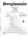
OWNERS MANUAL
MODEL
CC500
IS CERTIFIED TO:
1
CSA B140.7.1
CAN/CSA B366.1
UL391
UL726
Unit Serial #
Burner Serial #
Purchased From
Company Address
Name of Installer
Installer Telephone #
Date Installed
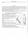
IMPORTANT
This manual must be given to the homeowner. Please read the warranty
and return the warranty card to initiate coverage.
We Strongly Recommend The Use Of A Carbon Monoxide Detector When
Using Any Product That Consumes Fossil Fuels.
It is the responsibility of the person or company installing this boiler to verify before the
installation that the boiler certifications shown on this page, meet or exceed all local, state and
regulatory requirements for installation and use of this boiler. Failure to do so voids all claims
and warranties.
June 2006
Aussi disponible en Francais.
KEEP THIS MANUAL FOR FUTURE REFERENCE. Follow all instructions
carefully for installation, maintenance & operation of the CC500 boiler.
TABLE OF CONTENTS
1.
2.
3.
4.
5.
6.
7.
8.
9.
10.
11.
12.
13.
Taking Delivery & Unpacking
Assembly
Chimney and Smoke Pipes
Placement of the Unit
Installation Clearances
Fuel Tank Supply
Combustion Air
Very Important homeowner information
Aquastat Settings
Oil Burner Installation
Installation of Blocked Flue Sensor
How Much Water to Run in System
Electrical
Piping
Adjustments of Damper Motor and Chain (Diagram)
Operating Instructions (Wood Section)
Normal Operation
Operating Instructions (Oil Section)
To Start the Burner
To Stop the Burner
To Stop the Burner for an Extended Period of Time
To Start the Burner after an Extended Shutdown
If the Burner Fails to Operate
When the Burner is in Operation
Special Procedures
Extreme Wood Fire
Flue Fire
Electrical Power Failure
To Reset Combustion Controls
General Maintenance Pointers
Burner Maintenance
Care of the Boiler When Not in Use
Replacing Hot Water Coils
Cleaning and Servicing Wood Section
Cleaning and Servicing Oil Section
Cleaning and Servicing Oil Section Continued (Diagram)
To Clean the Oil Burner
To Clean the Oil Filter
To Clean the Strainer
Chimney Connections (Diagram)
Piping and Wiring Layout (Diagram)
Electrical (Diagram)
Domestic Hot Water & Mixing Circulator (Diagram)
TAKING DELIVERY AND UNPACKING
Note: The consignee is responsible for ensuring that the packages have arrived in good condition. Examine the
packages for damages, if found, note the same on carriers' bill of lading and make a claim to the carrier.
Each unit is carefully inspected before leaving our factory.
Package (1) The crated boiler (assembled)
Package (2) The oil burner pack:
1 - Choice of Burner
1 - Damper Motor & Chain
1 - Nozzle
1 - Pressure Relief Valve
1 - Vz" Drain Valve
1 - Pressure Reducing Valve
1 - Single Aquastat
3 - Wells
1 - Tridicator
1 - N.O. Zone Valve
2-24 VA Transformers
1 - Wiring Harness
1 - Triple Aquastat
1 - Blocked Flue Sensor
1 - Triple Aquastat Relay
2 - Circulator Pumps c/w Flanges
Please note: The two circulator pumps are required for proper operation of this boiler.
Installation of this unit should be in accordance with the regulations of the authorities having jurisdiction. Reference
should be made to: hi Canada, CSA B139, "Installation Code for Oil Burning Equipment" for recommended
installation practices; In the United States, UL 391 "Solid-Fuel and Combination-Fuel Central and Supplementary
Furnaces " and UL 726 "Oil Fired Boiler Assemblies".
ASSEMBLY
Benjamin "CC500" boilers are factory assembled. The burner and controls are field mounted using the wiring
harness supplied. Other wiring for the thermostats and zone valves are not supplied.(see wiring diagram on page
12)
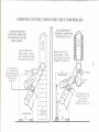
CHIMNEY AND SMOKE PIPES
(For proper set up, see the diagram on page 10)
The specification of the chimney to be used must comply with the requirement that other than solid-fuel/oil
combinations and add-ons, wood burning appliances shall not be connected to a venting system serving an appliance
vented by another type of fuel. Connect the boiler to an approved solid fuel factory-built chimney: In CANADACAN/ULC S629 standard for 650° F chimney; In the UNITED STATES-UL103 Chimneys for Residential Type
and Building Heating Appliances, Factory Built or a safe, clean, sound condition, masonry chimney equipped with
an approved liner: In CANADA-CAN/ULC-S635-M90 Standard for Lining Systems for existing masonry or
Factory Built Chimneys and Vents; hi the UNITED STATES-UL1777 Chimney Liners (e.g., stainless steel, clay,
etc.). The chimney must be equivalent to a minimum of 7" round inside diameter, or 8" round maximum. The
chimney must be capable of maintaining a negative updraft at all times and in all conditions. Carefully inspect the
chimney for safety and dirt before making connections. Place the boiler as close to the chimney as possible.
The smoke pipe should be blue or black steel, 24 ga. or heavier. Use as few turns as possible between the boiler and
the chimney, as each 90° elbow adds 10' of restriction and a 45° elbow adds 5' of restriction. The draft regulator
should be 7 " diameter and set at -.04 W.C. to open. Install the regulator a minimum of 18 " and a maximum of 24 "
from the boiler breech. Avoid long horizontal runs of smoke pipe. Maintain a minimum of Vz" rise per foot of pipe
from the boiler to the chimney.
DO NOT run the pipe downhill from the boiler to the chimney. Confirm that the installation clearances are met
or exceeded. Secure all smoke pipe joints with three sheet metal screws in each joint.
DO NOT pass the smoke pipes through a wall, floor or ceiling to reach the chimney.
-1-
PLACEMENT OF THE UNIT
The CC500 should be as close to the chimney as possible. The CC500 can be installed on a COMBUSTIBLE floor
using a non-combustible pad extending 20" front and rear and 6" on each side. The boiler must be properly
LEVELED. A 1" (2.5cm) minimum air space must be maintained under the appliance. This can be achieved by
using four non-combustible blocks, a minimum of 1" (2.5cm) thick x 4" (10cm) wide x 8" (20cm) long, one to be
placed under each corner.
INSTALLATION CLEARANCES (very important)
Front:
48"
One Side:
6"
Rear:
24"
Other Side: 24"
Smoke Pipe: 18"
FUEL TANK SUPPLY
The fuel supply tank and fuel lines should be installed a minimum of 6' from the boiler and in accordance with
codes and standards having jurisdiction in your area. Use flared fittings only.
DO NOT use furl fittings. Protect the oil line from the wood fire door.
COMBUSTION AIR
To achieve satisfactory combustion, an adequate supply of fresh air is required. In confined areas, a grilled opening
shall be provided. The minimum total area of a grilled opening is 2 square feet. Where fans are used in the fuel
storage area, they should be installed so as not to create negative pressures in the room where the furnace is installed.
VERY IMPORTANT (READ CAREFULLY)
1. The furnace must be installed by a qualified technician currently active in the heating trade & meet
or exceed all local or national codes.
2. DO NOT TAMPER WITH THE UNIT OR CONTROLS - CALL A QUALIFIED SERVICE
TECHNICIAN.
3. Use No.2 furnace oil only. DO NOT USE GASOLINE, CRANKCASE DRAININGS, OR ANY OIL
CONTAINING GASOLINE. Use of other fuels could damage the unit or present a serious safety
hazard.
4. DO NOT use furnace oil in the solid fuel section.
5. DO NOT BURN GARBAGE OR PAPER IN THE UNIT OR LEAVE COMBUSTIBLE
MATERIALS AROUND THE UNIT.
6. Know the location of the emergency disconnect switch for the unit.
7. Contact a qualified service technician before remodeling, for annual service/maintenance, before
extended periods of shutdown and before start-up.
8. DO NOT stack items on or around the boiler - check required clearances on this page.
9. DO NOT store flammable materials in the vicinity of the furnace.
10. DO NOT start this unit all components are securely in place.
11. DO NOT start the wood or oil section until the boiler is properly filled with water (damage will
result voiding the warranty).
*Ensure that the water pressure reducing valve is working properly (set at 12 p.s.i.). Too high a pressure will
damage the boiler (voiding the warranty).
*Care must be taken to ensure that the boiler will not be exposed to thermal shock which can be caused when
the system return water temperature is more than 40° F below the system supply water temperature.
-2-
AQUASTAT SETTINGS
As shown on the wiring diagram on page 12.
Recommendation If Using The Domestic Hot Water Coils In The Boiler
When the wood section of your boiler is not in use for an extended period of time, change the oil aquastat setting
to a low limit of 1 SOT and a high limit, not to exceed 200°F. This is to better assist in the heating of the domestic
hot water.
CAUTION: Be sure to return the settings to the normal (low 150°F & high 170°F) before starting your
wood section again.
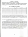
OIL BURNER INSTALLATION
Proper noz/les and settings for (Use No. 2 Furnace OiH:
BTU/Hour
Insertion
100 psi
101200
4.00"
l.OOgph
100 psi
118300
4.00"
Delevan 0.75 x 80°B
0.89 gph
140 psi
38625
106600
4.00"
Beckett AFG
Delevan 0.85 x 80°B
1.01 gph
140 psi
38626
118700
4.00"
Riello F5
Delevan 0.75 x 80°B
0.90 gph
145 psi
1.5
3.5
107000
4-1/8"
Hiello F5
Delevan 0.85 x 80°B
1 .02 gph
145 psi
3.25
3.75
120700
4-1/8"
Burner
Nozzle
Input
Pump
Pressure
Aero HF-US
Delevan 0.85 x 80°B
0.85 gph
Aero HF-US
Delevanl.OOx80°B
Beckett AFG
Turbulator
Initial
Air
The oil burner is mounted on the 3 studs provided on the lower front combustion chamber access panel. Extreme
care should be taken when mounting the burner, not to damage the molded combustion chamber.
The air opening on the oil burner should be adjusted to obtain a #0 Bacharach smoke spot. At this point, maximum
fuel efficiency is obtained. Having obtained the proper smoke spot, the following should be observed: The CO in
the flue should be between 10 and 13.5%. Draft setting - not to exceed -.04" W.C.. (the draft is adjustable by means
of adjusting the screw/wheel located on the front of the barometric draft regulator).
INSTALLATION OF BLOCKED FLUE SENSOR
Install the Field Controls WMO-1 in the oil flue pipe as given in the sensor installation instructions.
HOW MUCH WATER TO RUN IN THE SYSTEM
For hot water heating, beginning with the lowest radiator, open the vent and allow air to escape, closing the vent
when the water begins to flow from it. Repeat this on all other radiators, continuing to the second and then higher
floors. (Radiators equipped with automatic air vent valves do not require venting by hand except to speed up initial
filling of system). Check the water level regularly for loss due to leaks or evaporation. All systems must be provided
with an expansion tank and relief valve. Water should be fed to the system by means of an automatic fill valve
available for that purpose and backflow prevention must be used.
The relief valve should be opened occasionally to make sure it is operative. The relief valve should open when the
pressure indicated on the combination gauge exceeds thirty pounds. If this pressure is exceeded before the relief
valve opens, shut off the fill valve and drain the water from the system until the pressure is reduced below thirty
pounds and have the valve repaired or replaced immediately. A water logged air cushion tank is indicated by rapid
increase in pressure with only slight increase in temperature, or frequent escape of water from the relief valve.
CHECK THE SAFETY RELIEF VALVE ON THE BOILER MONTHLY. Test the safety relief valve by
momentarily pulling the lever to observe free escape of hot water.
NOTE: Drain pipes from the safety relief and the boiler drain valves shall be piped to a safe drain.
-3-
ELECTRICAL
Electrical installations must conform to all local and national codes and standards as their jurisdiction may apply.
See page 12.
PIPING
Pining must conform to all local and national codes and standards as their jurisdiction may apply. See pages 11&
13. The dump zone should be your existing largest zone (that has all piping above the boiler.-e.g. Livingroom or
master bedroom). With a home built on slab or heating with an underfloor radiant system, a separate zone should
be added above the
boiler. This zone would be of adequate size to dissipate at least 15,000 btu/hr. The piping must
be a minimum of3//' (18 mm) diameter and able to withstand a minimum temperature of 225°F (107°C). This loop
shall be such that it can only be made inoperative by a deliberate manual action.
Please ensure that the pressure relief valve and the boiler drain valve are piped to a safe drain (water discharging
from either could be extremely hot and dangerous).
All piping will be such that excessive pressure will not be developed in any portion of the boiler or system.
NOTE: It is important to install a throttle flow valve in order to control the flow of water through the domestic
water system. Set the valve to regulate the flow at the required temperature.
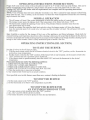
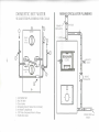
ADJUSTMENTS OF DAMPER MOTOR AND CHAIN
The damper chain should be adjusted when the damper door is in
the down position. In this position the chain should be adjusted
so there is a small amount of slack.
The amount of lift or opening of the damper door is adjusted by
moving the two pinch nuts on the stove bolt thread closer 3 or
further away from the lift strap. The damper should be set at A"
to 1" opening. After proper adjustment of the draft chain and
damper door the thermostat and aquastat will keep the fire within
safe limits.
CAUTION: This setting should not be altered for
increased firing, for any reason.
DAMPER MOTOR
BOILER
FRONT
NOTE:
- DO NOT use automatic stoking or sawdust fueling on
PINCH
this boiler.
NUTS
- DO keep the boiler area clean and clear of all debris at
all times.
- DO NOTbum gasoline, naphtha, kerosene, engine oil, (fuel oil
in the wood section) or other volatile, creosote soaked wood or
drift wood. (Damage to your boiler will result and void the
warranty.)
- This boiler will burn most wood fuels. However, it is
recommended that dry, untreated, natural hardwood be used as
FIREDOOR
much as possible. It affords cleaner more efficient burning with
less soot, creosote and ash build-up, as well as less frequent firing intervals.
- Store wood in neat, well supported piles at least 4 feet from the charging door.
- To prevent injury, DO NOT allow anyone who is unfamiliar with the operation of the boiler to attend it.
MAGNIFIED
-4-
OPERATING INSTRUCTIONS (WOOD SECTION)
Proper draft in the wood section will not be achieved until 2" to 3" of ash is built up in the firebox. This can be
readily accomplished using softwoods, which creates ash quickly or use clean sand (with "no salt" in it).
Caution: DO NOT fire this boiler until all requirements are complete and the operating instructions
are fully understood.
NOTE: Your oil burner may start even when the wood fire is on. This is caused by large amounts of heat being
taken from the unit. This is normal, as the oil burner will boost the water temperature around the coils ensuring
ample domestic hot water.
NORMAL OPERATION
1. The oil burner will start if the system temperature is below the setting on the oil control aquastat.
2. The damper motor opens the damper door if the temperature of the boiler falls below 170 F.
3. The thermostats control the opening of zone valves. The primary (House) circulator runs when the
zone thermostats call for heat.
4. Should an extreme fire cause the high limit switch to close, the damper motor will close the damper
door, the normally open (N.O.) zone valve will open and the circulator will start. The oil burner will not be
able to start
Note: Establish a routine for the storage of fuel, care of the appliance, and firing techniques. Check daily for
creosote build up, until experience shows how often cleaning is necessary. Be aware that the hotter the fire, the less
creosote is deposited and weekly cleaning may be necessary in mild weather even though monthly cleaning may be
enough in the coldest months. Have a clearly understood plan to handle a flue fire.
OPERATING INSTRUCTIONS (OIL SECTION)
TO START THE BURNER
See that all valves in the oil lines are open.
1. With the main cutout switch for the oil burner electrical circuit in the "OFF" position, set the thermostat at a
point above room temperature.
2. Set the electric switch to the "ON " position. If the burner fails to start instantly, set the master switch to the
"OFF" position and call a qualified service technician.
3. If the burner starts to operate normally leave the switch"ON" and reset the thermostat to the desired
temperature.
Never start the burner under the following conditions:
1. WHEN EXCESS OIL HAS ACCUMULATED.
2. WHEN OIL VAPORS ARE PRESENT.
3. WHEN THE COMBUSTION AREA IS VERY HOT.
4. WHEN THE CLEAN OUT COVERS ARE NOT SECURE.
5. When the smoke pipe is removed or blocked.
6. Any situation that would lead to an unsafe condition.
Never push the reset on the burner more than once; contact a heating technician.
TO STOP THE BURNER
1. Set the main cutout to the "OFF" position.
2. Set the thermostat as far below room temperature as possible.
TO STOP THE BURNER FOR
AN EXTENDED PERIOD OF TIME
1. The main cutout switch should be set to the "OFF" position.
2. ALL OIL VALVES SHOULD BE CLOSED.
3. The burner should be covered to protect it from dust and dampness.
-5-
TO START THE BURNER AFTER
AN EXTENDED SHUTDOWN
1. The strainer in the pump should be cleaned, and if a filter is installed in the oil line, it should be cleaned and
the filter cartridge replaced.
2. The fan and the blower housing should be cleaned and the air filter replaced.
3. The ignition points should be checked and the nozzle cleaned and replaced.
4. Oil the motor.
5. Start the burner by following the instructions under the paragraph, "TO START THE BURNER".
7. It is recommended that a qualified service technician be called to clean the unit and burner and make sure
that the burner is operating properly. The installer should identify the emergency shut off switch and valves.
IF THE BURNER FAILS TO OPERATE
Call a qualified service technician. The trouble may be due to:
1. Blown fuses in the electrical circuit.
2. The thermostat may be set below room temperature.
3. Combustion control may require "resetting" (DO NOT press the reset more than two times).
4. The oil valve may be closed.
5. The oil supply may be too low.
6. The blocked flue sensor may be tripped.
WHEN THE BURNER IS IN OPERATION
1. Check the flame periodically, if it becomes out of shape or smoky, call your serviceman.
2. When cleaning the boiler room or utility room, always stop the burner to reduce the amount of dust and lint
drawn into the burner.
3. The electric ignition system and all controls should be checked periodically for reliability of operation and
adjusted if necessary.
SPECIAL PROCEDURES
1.
2.
3.
4.
5.
EXTREME WOOD FIRE (Due t9 improper operation)
Disconnect the damper chain to prevent the damper door from opening.
Block the over-fire draft slot in the door.
Increase all thermostats to maximum.
Excessive heat may cause safety relief valve to open. (Ensure it is piped to a safe drain.)
DO NOT shut power off.
1.
2.
3.
4.
5.
6.
Call the Fire Department.
Prepare to evacuate the house.
Shut off the main power switch to the boiler.
Diminish the fire in the boiler by closing all combustion air openings.
DO NOT remove the flue pipes until the fire is completely out.
Have the chimney inspected and repair the flue before using it again.
FLUE FIRE
-6-
i
ELECTRICAL POWER FAILURE
NOTE: DO NOT operate your appliance, unless your total heating system has been designed and installed to
operate properly
without electricity.
1. Maintain 1A the normal fire load.
2. The air damper must be manually operated. (DO NOT prop or tie open.)
3. Fire the boiler carefully. Remember you are now on gravity circulation only. It is necessary to
manually open the zone valve (if used). Each system is different, extreme care must be used until a safe rate
.of firing is known for your system, in a no power situation.
TO RESET COMBUSTION CONTROLS
The reset control consists of an electrical relay operating in conjunction with a flame detector mounted on the oil
pipe of the drawer assembly of the burner. When for any reason the burner fails to ignite promptly the control will
stop the burner. After being shut off in this manner, the burner cannot again be started until the control is "RESET".
The burner mounted relay is attached to the burner housing and is reset by pushing the "RESET" button and then
releasing. DO NOT press the reset button more than twice. Call a qualified service technician.
The blocked flue sensor is designed to shut off the burner in the event that the flue has become blocked. When this
has happened, the burner cannot be started again until the sensor has been reset. Pushing in the red button, which
is accessed through the hole in the front of the sensor, resets the sensor. Only try this once and then call a
qualified service technician.
GENERAL MAINTENANCE POINTERS
1. Keep the flues in the boiler clean. Because soot is a nonconductor of heat, a dirty boiler requires more fuel to
heat a house than a clean one.
2. The smoke pipe should be taken off at least once a year and thoroughly cleaned of all soot.
3. If you wish to leave the boiler shut off during freezing weather, first drain all the water from the entire
heating system; this includes all the piping and the radiators themselves.
BURNER MAINTENANCE
Use the following checklist when performing annual burner service. To be performed by a qualified service
technician.
D Replace the oil supply line filter. The filter body should be thoroughly cleaned before installing a new
cartridge.
D Remove and clean the pump strainer (if applicable).
D Replace the nozzle with an equivalent nozzle.
D Clean and inspect the electrodes for damage, replacing any that are cracked or chipped.
D Check electrode tip settings.
D Inspect the transformer contacts.
D Clean the cad cell.
D Oil the motor (if applicable) a good grade of medium detergent-free automobile engine oil should be used.
Twice each year one table spoon of oil should be poured slowly into the oil cup
D Clean the blower wheel, air inlet, retention head and throttle plate of any lint or any foreign material.
D Check all wiring for secure connections or insulation breaks.
D Check the pump pressure.
D Adjust the burner to proper settings on page 3 "using proper instruments".
-7-
CARE OF THE BOILER WHEN NOT IN USE
When the boiler is out of service for an extended period of time, carefully and thoroughly clean the smoke pipe,
chimney, firebox and any part which has been in contact with hot gases. This is extremely important as rusting and
corrosion occur when the boiler is idle.
REPLACING THE HOT WATER COILS
The rear casing panel of your boiler must be removed to gain access to the hot water coils mounting plates. It is
necessary to remove the smoke pipes before removing the rear panel. (ENSURE THAT NO FIRE IS PRESENT
AND POWER DISCONNECTS ARE OFF BEFORE REMOVING SMOKE PIPES). The water must be drained
from the boiler before removing coil mounting plates, ensure the water supply to the coils is off before removing.
Two openings are provided in your boiler for hot water coils.
CLEANING AND SERVICING (WOOD SECTION)
It is necessary to remove ash and occasionally brush the inner surfaces with a wire brush and check the smoke pipe
for ash or creosote as necessary. Leave 2" of ash in the wood firebox when cleaning, to aid in combustion.
IMPORTANT: Fire can be caused by improper storage of ashes containing dormant hot coals. Store
ashes in a tightly covered metal container. DO NOT place other waste in this container.
VERY IMPORTANT: Replace all damaged or worn gaskets before reassembling. Fire door gaskets and seals
must be maintained in good condition for safe operation.
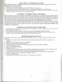
CLEANING AND SERVICING (OIL SECTION)
IT IS HIGHLY RECOMMENDED THAT A QUALIFIED SERVICE TECHNICIAN (REGULARLY ENGAGED IN
THE HEATING TRADE) BE EMPLOYED TO DO THE CLEANING AND SERVICING.
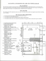
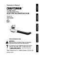
Your Benjamin "CC500" boiler is equipped with one of the most modern molded combustion chambers available.
However, it is easily damaged and care must be taken handling it. To remove the chamber, (see diagram right} first
remove the oil burner (8) from the three mounting studs, then remove the combustion chamber access panel (6) by
means of two nuts and bolts. Use extreme care when removing the panel, as the combustion chamber is mounted
on the rear of the panel. The combustion chamber is removed by loosening the bolt on the metal clamping ring (13),
releasing the combustion chamber. The new combustion chamber is installed by reversing the order of removal.
(INSPECT ALL INNER SURFACES AND BAFFLES, CLEAN BEFORE REPLACING.)
At least once a year (preferably at the end of the heating season), thoroughly clean the inner surfaces of the boiler,
the flue passages, flue pipe and chimneys. It is recommended that a properly equipped service technician do this job.
Once yearly or as necessary, remove the oil burner by means of three nuts. Inspect and service the burner. Remove
the oil chamber access panel by means of four nuts. It may be necessary to remove the combustion baffles 10 and
14 by means of 2 screws (12). Clean the inner surfaces with a wire brush. (DO NOT USE A WIRE BRUSH ON
THE COMBUSTION CHAMBER, DAMAGE WILL RESULT.) Also inspect the smoke pipe and flue for ash or
creosote buildup and clean if necessary.
-8-
CLEANING AND SERVICING (OIL SECTION)continued
OIL BURNER
The oil burner should be removed at least once each heating season, cleaned and serviced. Also inspect and
clean any accumulated soot and debris from the combustion chamber and transfer duct. Inspect and replace the
burner gasket if necessary. To be performed by a Qualified Service Technician.
OIL FILTER
The cartridge should be replaced at least once a year. The filter body should be thoroughly cleaned before installing
a new cartridge.
1.
2.
3.
4.
TO CLEAN THE STRAINER
Oil valves between the tank and the burner should be closed.
The strainer cover should be removed.
The strainer basket should be taken out and washed with kerosene.
The strainer basket and covers should be reassembled with gaskets that are clean and in good condition.
1. LOADING DOOR FOR WOOD
2. INNER DOOR SHIELD
3. WOOD FLUE BAFFLE
(ORDER # CC524)
4. SMOKE PIPE - WOOD-7" I.D.
5. DOMESTIC HOT WATER COIL X 2
(ORDER # CC552)
/<
V
6. OIL CHAMBER ACCESS PANEL
(ORDER # CC539)
GASKET
(ORDER # CC603)
7. SIGHT PORT DOOR
(ORDER # CC592)
GASKET
(ORDER # CC593)
8. OIL BURNER
9. OIL COMBUSTION CHAMBER
(ORDER # CC598)
10. STEEL COMBUSTION BAFFLE
(ORDER # CC597)
11. SMOKE PIPE - OIL-7" I.D.
12. OIL BAFFLE SPACER
(ORDER # CC604)
13. COMBUSTION CHAMBER
SUPPORT ASSEMBLY
(ORDER # CC636)
14. STAINLESS COMBUSTION
BAFFLE
2)
WOOD
SECTION
(ORDER # CC533)
15. OIL FLUE BAFFLE
(ORDER # CC535)
16. COIL GASKET
(ORDER # CC586)
-9-
r3
CHIMNEY CONNECTIONS FOR THE CC500 BOILER
A LINED MASONRY
CHIMNEY APPROVED
FOR BURNING SOLID
FUEL SAFELY.
SMOKE PIPE MUST
HAVE A MIN. W PER
FOOT RISE FROM THE
BOILER TO THE FLUE.
AN APPROVED 7"
C.S.A. BAROMETRIC
DRAFT REGULATOR
MAX. FLUE DRAFT
SETTING 0.04
INCH W.C.
4" MIN.—^
FACTORY BUILT
CHIMNEY APPROVED
FOR SOLID FUELS
SMOKE PIPE MUST
HAVE A MIN. 1/2" PER
FOOT RISE FROM THE
BOILER TO THE FLUE.
WHMK
J
4"MIN.
CLEANOUT
TEE
AN APPROVED 7'C.S.A.
BAROMETRIC DRAFT
REGULATOR
MAX. FLUE DRAFT
SETTING 0.04 INCH W.C
CCSOO BOILER
o
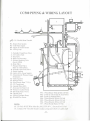
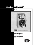
CC500 PIPING & WIRING LAYOUT
P2
;;£"*-3/8 Flexible Metal Conduit
PI - Return From System
P2 - Cold Water Supply
P3 - Supply To System Zones
P4 - Mixing Loop
1 - Normally Closed Zone Valve
2 - Air Cushion Tank
3 - Stop Valve
4 - Back Flow Preventer
5 - Pressure Reducing Valve
(SetAtl2PSI)
6 - Drain Valve
7 - Pressure Relief Valve
(Pipe To A Safe Drain)
8 - Normally Open Zone Valve
9 - Single Aquastat
10 - Line In (120v Power Supply)
11 - Temperature & Pressure Gauge
(Indicator)
12 -Triple Aquastat
13 -Damper Motor
14-Wood Smoke PipeC 7 "I. D
15 - 24V Transformer
16 - Aquastat Relay (Oil)
17 - Domestic Hot Water Coil
18 - Primary Circulator Pump
1 9 - O i l Smoke Pipe( 7"1.D.)
20 Throttle Valve
21 - Mixing Circulator Pump'
•»•> - Blocked Flue Sensor
22
W!
"3 Wire < Black - whlte & Red> I2 ° Volt
- 24 Volt To Thermostats & Zone Valves
W3 24 Volt Io Dam er Motor
"
P
W4 - 2 Wire (Black & White) 120 Volt
W5 - 2 Wire (Black & White) 120 Volt
W6 - 2 Wire (Black & White) 120 Volt
W2
W7 2 wire Red & Black I2 Volt
NOTE:
'
^
> °
All 120 Volt, 60 HZ Wire Must Be 16(1 TEW 90' C, Encased In CSA or
UL Certified 3/&" Flexible Metal Conduit, using anti-shorts in cable ends
-11-
LINE IN
115 VI 1 760 Hz
White ("Neutral)
WOOD
Triple Aquastat
Single Aquastat
Damper Motor
Low Limn
High Limit
set20(ff
24 Volt
IVansformcr
Normally Open
Zone Valve
MAXIMUM LOAD 30 VA (LOAD 24V)
Black
OILAqii
NOTE: If you are using the
domestic coils from the boiler
adjust the oil aquastat to
LOW-18CHF and HIGH-200"F
for the summer months.
W.R. Benjamin Products Limited
Wiring schematic for
CC500 COMBINATION
WOOD/OIL BOILER
MAY 2006
Burner Control
N C Z.V. -- Normally Closed Zone Valve
N O Z.V. — Normally Open Zone Valve
MO
Motor
120 Volts 60 HZ
24 Volts
AERO OR
BECKETT
BURNER
DOMESTIC HOT WATER
MIXING CIRCULATOR PLUMBING
SUGGESTED PLUMBING FOR COILS
PRIMARY
CIRCULATOR
TO HOUSE
1 ViFEED-
BALANCE
VALVE
MIXING
CIRCULATOR
1, Cold Water Inlet
2, Shut Off Valve
3, Check Valve
4, Tempering Valve (8" below the coil Outlet)
5, Hot Water To Appliances
6, 120°F Max, Tempered Water to Fixtures
7, Throttle Flow Valve
RETURN FROM —
HOUSE