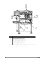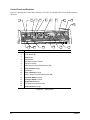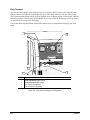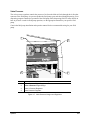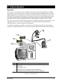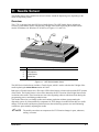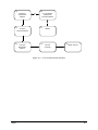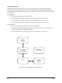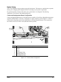
1
Asymtek Century Series Operations Manual The hardcopy part number for this manual is 196034, Revision A. The CD part number is 196035, Revision A. To reorder this manual, please contact Asymtek, 1-760-431-1919. Revision History Revision Date A 5/01 Description Initial Release Pages Affected All NOTICE All information contained in or disclosed by this document is considered proprietary by Asymtek. By accepting this material the recipient agrees that this material and the information contained therein are held in confidence and in trust and will not be used, reproduced in whole or in part, nor its contents revealed to others, except to meet the purpose for which it was delivered. It is understood that no right is conveyed to reproduce or have reproduced any item herein disclosed without express permission from Asymtek. Asymtek provides this manual "as is," without warranty of any kind, either expressed or implied, including, but not limited to, the implied warranties of merchantability and fitness for a particular purpose. Asymtek may make improvements or changes in the product(s) or programs described in this manual at any time. These changes will be incorporated in new editions of this publication. Asymtek assumes no responsibility for the accuracy, completeness, sufficiency, or usefulness of this manual, or for any problem that might arise from the use of the information in this manual. COMMENTS As part of our continuing effort to maintain the highest standards of quality in our publications, we solicit your comments on the accuracy, clarity, organization, and usefulness of this manual. Please mail, fax, or E-mail your comments addressed to the attention of Asymtek Technical Publications at the appropriate address below. Asymtek Headquarters 2762 Loker Avenue West Carlsbad, CA 92008-6603 USA Toll Free: Tel: Fax: E-mail: Website: 1-800-ASYMTEK (1-800-279-6835) +1-760-431-1919 +1-760-431-2678 [email protected] www.asymtek.com Toll Free: 1-800-ASYMTEK (1-800-279-6835) Technical Support Asymtek®, Century®, DispenseJet®, Heli-flow™, and Fluidmove® are registered trademarks of Asymtek. Microsoft® , Windows®, and Windows NT® are registered trademarks of Microsoft Corporation. NER DOAL® and Diffuse On-Axis Light™ are registered trademarks of Northeast Robotics. Pentium® is a registered trademark of Intel Corporation. © Asymtek, 2001 Manual Conventions Bold text indicates a menu selection, button selection, switch position, label, Bold Text computer command, filename, file location, internet address or other information that must be clicked on, typed or noted by the user. [Bracketed Text] [Bracketed Text] indicates a key to press or a keyboard sequence, such as [Enter] or [Alt + Tab]. WARNING! CAUTION! ? NOTE Safety Warning. This symbol will appear in a highlighted text block. The information in the text block warns you about actions that could cause serious bodily harm to the user. Machinery and Software Caution. This symbol will appear in a highlighted text block. The information in the text block warns you about actions that could cause serious damage to the machinery or software. This symbol appears next to a text block with information you must know before proceeding, or with helpful information relating to text that precedes it. TIP This symbol appears next to a text block with a timesaving or technique tip. HELP This symbol appears next to a text block with instructions for error recovery. i TABLE OF CONTENTS 1 GETTING STARTED ..............................................................................................1-1 Overview ..............................................................................................................................................1-1 System Status ......................................................................................................................................1-1 Safety ...................................................................................................................................................1-1 Manuals Supplied ................................................................................................................................1-2 Which Manuals to Use .........................................................................................................................1-3 2 INTRODUCTION.....................................................................................................2-2 Overview ..............................................................................................................................................2-2 Basic System Description ....................................................................................................................2-2 System Features ..................................................................................................................................2-2 3 SAFETY ..................................................................................................................3-1 Overview ..............................................................................................................................................3-1 Safety Precautions ...............................................................................................................................3-1 Safety Warning Labels.........................................................................................................................3-3 Emergency Shutdown..........................................................................................................................3-6 Integrated Safety Systems...................................................................................................................3-8 ESD Precautions................................................................................................................................3-11 4 OPERATION ...........................................................................................................4-1 Overview ..............................................................................................................................................4-1 Theory of Operation .............................................................................................................................4-1 Operation .............................................................................................................................................4-1 Dispenser Operation ............................................................................................................................4-4 Computer System ................................................................................................................................4-4 Specifications for Computer System....................................................................................................4-4 Gauges and Regulators .....................................................................................................................4-16 5 STARTUP/SHUTDOWN .........................................................................................5-1 Startup..................................................................................................................................................5-1 Machine Offsets Procedures................................................................................................................5-3 Shutdown .............................................................................................................................................5-7 6 TROUBLESHOOTING ............................................................................................6-1 Software Troubleshooting ....................................................................................................................6-1 System Troubleshooting ......................................................................................................................6-2 Testing System Repeatability ..............................................................................................................6-5 7 MAINTENANCE ......................................................................................................7-1 Routine Maintenance ...........................................................................................................................7-1 System Maintenance ...........................................................................................................................7-2 8 SYSTEM SPECIFICATIONS...................................................................................8-1 9 VISION SYSTEM ....................................................................................................9-1 Overview ..............................................................................................................................................9-1 Theory of Operation .............................................................................................................................9-2 Operation .............................................................................................................................................9-2 Adjustments for the Pattern Recognition System ................................................................................9-2 Vision System Troubleshooting ...........................................................................................................9-2 Specifications for Pattern Recognition System....................................................................................9-4 10 HEIGHT SENSOR ................................................................................................10-1 Overview ............................................................................................................................................10-1 Theory of Operation ...........................................................................................................................10-1 Operation ...........................................................................................................................................10-1 Height Sensor Setup..........................................................................................................................10-1 Probe Adjustments for HS-Series ......................................................................................................10-9 ii Height Sensor Troubleshooting .......................................................................................................10-16 Specifications for HS Series RT.......................................................................................................10-17 11 NEEDLE SENSOR................................................................................................11-1 Overview ............................................................................................................................................11-1 Theory of Operation ...........................................................................................................................11-2 Operation ...........................................................................................................................................11-2 Needle Sensor Setup.........................................................................................................................11-2 Tactile Sensor ....................................................................................................................................11-3 Needle Sensor Troubleshooting ........................................................................................................11-5 Specifications for Needle Sensor.......................................................................................................11-5 12 NEEDLE HEATER ................................................................................................12-1 Overview ............................................................................................................................................12-1 Theory of Operation ...........................................................................................................................12-1 Operation ...........................................................................................................................................12-1 Temperature Controller, 4- or 8-Channel...........................................................................................12-4 Needle Heater Setup .........................................................................................................................12-4 Needle Heater Troubleshooting .........................................................................................................12-6 Specifications for 4- and 8-Channel Temperature Controllers and Needle Heater Element.............12-7 13 SPECIAL OPTIONS..............................................................................................13-1 Dual-Action Dispensing Head ............................................................................................................13-1 Specifications for Dual-Action Dispensing Head ...............................................................................13-6 External I/O ........................................................................................................................................13-7 Hour Meter .......................................................................................................................................13-11 Low Air Pressure Sensor .................................................................................................................13-12 Magnetic Fluid Level Sensor............................................................................................................13-14 14 CONVEYORS .......................................................................................................14-1 Overview ............................................................................................................................................14-1 Theory of Operation ...........................................................................................................................14-2 Operation ...........................................................................................................................................14-2 Conveyor Maintenance ......................................................................................................................14-3 Conveyor Troubleshooting.................................................................................................................14-5 15 HEATERS .............................................................................................................15-1 Overview ............................................................................................................................................15-1 Contact Heaters .................................................................................................................................15-1 Impingement Heaters.........................................................................................................................15-3 Theory of Operation ...........................................................................................................................15-4 Operation ...........................................................................................................................................15-4 Heater Setup ......................................................................................................................................15-7 Heater Troubleshooting ...................................................................................................................15-10 Specifications for Contact and Impingement Heaters .....................................................................15-12 GLOSSARY................................................................................................ GLOSSARY-1 INDEX ................................................................................................................. INDEX-1 iii Table of Figures Figure 2-1 C-721 Front View .................................................................................................................................... 2-2 Figure 2-2 Dispensing Area Close-up....................................................................................................................... 2-3 Figure 2-3 Lower Cabinet ......................................................................................................................................... 2-4 Figure 2-4 Rear View................................................................................................................................................ 2-8 Figure 2-5 Rear View Close-Up................................................................................................................................ 2-9 Figure 3-1 Warning Labels, Front View .................................................................................................................... 3-4 Figure 3-2 Warning Labels, Rear View..................................................................................................................... 3-5 Figure 3-3 EMO Location on Dispenser Control Panel............................................................................................. 3-6 Figure 3-4 Optional Interlock Warning Tag............................................................................................................... 3-9 Figure 3-5 Main Power Inlet and Main Power Circuit Breaker ................................................................................ 3-11 Figure 4-1 Computer Faceplate................................................................................................................................ 4-3 Figure 4-2 Control Panel .......................................................................................................................................... 4-6 Figure 4-3 Light Beacon ......................................................................................................................................... 4-12 Figure 4-4 Main Air and Conveyor Air Gauges and Regulators.............................................................................. 4-14 Figure 4-5 Fluid and Valve Pneumatic Fittings (Connections shown for DP-3000) ................................................ 4-16 Figure 4-6 Fluid Pressure Gauges and Regulators ................................................................................................ 4-17 Figure 4-7 Valve Pressure Gauges and Regulators ............................................................................................... 4-18 Figure 4-8 Digital Pressure Gauges ....................................................................................................................... 4-20 Figure 4-9 Digital Pressure Gauges ....................................................................................................................... 4-21 Figure 7-1 Water Trap .............................................................................................................................................. 7-3 Figure 7-2 Replacing the Purge Boot ....................................................................................................................... 7-5 Figure 7-3 Replacing Purge Station Cups ................................................................................................................ 7-6 Figure 8-1 Vision and Dispensing Areas—Single Pump........................................................................................... 8-3 Figure 8-2 Vision and Dispensing Areas—Dual-Action Pump .................................................................................. 8-4 Figure 9-1 Vision System ......................................................................................................................................... 9-2 Figure 10-1 Height Sensor Installation ................................................................................................................... 10-4 Figure 10-2 Height Sensor Installation with Bracket Spacer................................................................................... 10-4 Figure 10-3 Tactile Height Sensor .......................................................................................................................... 10-5 Figure 10-4 Height Sensor Configuration Dialog Box (FmNT)................................................................................ 10-7 Figure 10-5 Probe-to-Needle Alignment ............................................................................................................... 10-10 Figure 10-6 Gear Up (GU) Adjustment Locations................................................................................................. 10-12 Figure 11-1 NSZ Series Needle Sensor ................................................................................................................. 11-1 Figure 11-2 Tactile Sensor Exposed ...................................................................................................................... 11-2 Figure 12-1 HT-04 .................................................................................................................................................. 12-2 Figure 12-2 HT-06 .................................................................................................................................................. 12-3 Figure 12-3 HT-10N................................................................................................................................................ 12-3 Figure 12-4 HT-06 on a DV-6000 Pump with Luer Lock Fitting .............................................................................. 12-5 Figure 12-5 HT-10N on a DV-6000 Pump .............................................................................................................. 12-6 Figure 13-1 Dual-Action Dispensing Head for Century C-721 ................................................................................ 13-2 Figure 13-2 Dual-Action Dispensing Head with Fluid Pumps Detached ................................................................. 13-3 Figure 13-3 Top View, Cover Removed; External I/O Connectors ......................................................................... 13-7 Figure 13-4 Hour Meter ........................................................................................................................................ 13-11 Figure 13-5 Low Air Pressure Sensor................................................................................................................... 13-12 Figure 13-6 Magnetic Fluid Level Sensor ............................................................................................................. 13-14 Figure 14-1 Typical Single-Lane Conveyor Configuration (Contact Heaters) ......................................................... 14-2 Figure 14-2 Typical Single-Lane Conveyor Configuration (Impingement Heaters).................................................14-3 Figure 15-1 Contact Heater .................................................................................................................................... 15-2 Figure 15-2 Impingement Heater............................................................................................................................ 15-3 Figure 15-3 C-721 Contact Heater Operation......................................................................................................... 15-5 Figure 15-4 C-721 Impingement Heater Operation ................................................................................................ 15-6 Figure 15-5 Contact Heater Configuration.............................................................................................................. 15-8 Figure 15-6 Tooling Mode Switch (Impingement/OFF/Contact) ........................................................................... 15-11 iv 1 Getting Started Congratulations on your choice of a Century C-721 Series Advanced IC Encapsulation dispensing system! Overview This manual is intended primarily as a reference for production operators. However, process engineers and service technicians unfamiliar with Asymtek products may also find this manual useful as a general introduction to the system. The objective of this manual is to provide a general introduction to the Century Series dispensing system, to identify all major system components, to explain the function of all major system components and to provide basic operation instructions. This section helps you check the material that arrived with your system and gets you started using the documentation. System Status The Century Series dispensing system is completely installed and tested onsite by Asymtek Technical Support. To ensure that the system is in good working order, only Asymtek technicians should be allowed to install it or move it. Safety Operation of the Century Series dispensing system involves heat, air pressure, pneumatic devices, electrical power, and may involve the use of hazardous materials. Read the enclosed product literature in its entirety before attempting any system or component operation. It is essential for every person working on or around the dispensing system to fully understand the hazards, risks and safety precautions associated with operating the system. When properly used, the dispensing system is safe and trouble-free. Consult the Material Safety Data Sheet (MSDS) for all fluids used with the dispensing system for proper use and disposal instructions and precautions. Getting Started 1-1 Manuals Supplied Your Century Series dispensing system arrives with manuals for installation and operation of major system components and software. For some system components, you may receive Original Equipment Manufacturer (OEM) manuals. Generally, these OEM manuals are only needed for reference and advanced troubleshooting. Consult only Asymtek manuals unless directed to do otherwise by Asymtek Technical Support or by Asymtek documentation. Below is a sample list of Asymtek manuals that may be shipped with a Century Series system configuration. OEM manuals supplied will vary with the options installed on your system: 1-2 • Century Series C-721 Operations Manual • Fluidmove for Windows NT User Guide • Fluid Pump Installation and Operations Manual (specific to your pump) • Best Dispensing Practice for Using the DJ-2100 to Dispense Surface Mount Adhesive (optional) Getting Started Which Manuals to Use Below is a guide to when each manual will be most useful to you. The level of the intended user is also indicated. Table 1-1 Use of Manuals Manual Century C-721 Operations Manual Fluidmove for Windows NT User Guide Getting Started When Used For Operation Instructions, Operator-performed Maintenance and Service For Operation, Programming, Software Troubleshooting Intended User Operators, Process Engineers, and Service Technicians Operators, Programmers, and Process Engineers 1-3 2 Introduction Overview The Century Series Advanced Integrated Circuit Encapsulation (AICE) systems are designed to solve the diverse needs of the emerging flip chip underfill and IC encapsulation market. The Century Series C-721 Dispensing System provides a modular approach to hardware, software, and factory integration. Advanced platform architecture provides precision control for reliable fluid delivery, with closed-loop thermal management, multi-zone substrate heating, and flexible material handling capabilities. The Century C-721 system features a SMEMA-compatible material handling system that can be configured for a variety of substrate types and sizes. Process carriers, lead frames, and multiple substrate carriers are all supported. Optional contact or impingement part heaters ensure reliable and flexible substrate heating. An integrated vision system for flip chip corner detection automatically corrects any workpiece misalignment. Asymtek’s exclusive Fluidmove for Windows NT (FmNT) software controls all machine parameters and events within a familiar Windows environment. Key safety features meet Common European (CE) standards. Basic System Description All Century Series dispensing systems begin with a standard platform. Modular components are added, allowing the system to be configured for common AICE applications. Your system was configured for your application at the Asymtek factory prior to shipping. Detailed descriptions of all features are found later in this section. Basic Platform • Computer system • Vision system • Light beacon • Vision system lighting • Motorized conveyor width adjust • Fluid pump quick refill • Vacuum-operated purge station • O-ring conveyor • Fluidmove for Windows NT software • Two-station lift tables • Needle sensor • Temperature controller Optional Modular Components • Part heaters (contact or impingement) • Dual-action dispensing head • Fluid dispensing pumps • Low air pressure sensor • Needle heater • Low fluid sensor • Height sensor • Hour meter System Features The figures in this section show views and features of the dispensing system. Callouts locate major components, options, and switches seen in each illustration. Paragraphs following the views briefly describe each feature. Introduction 2-1 System Front Views 3 4 2 1 5 Valve 2 Pressure Valve Pressure Fluid 2 Pressure DP2-42N 1MPa Fluid Pressure DP2-42N OUT1 OUT2 MODE 0 - ADJ 1MPa Abort OUT1 OUT2 MODE 0 - ADJ 0 SUNX 0 SUNX Pause 9 8 7 6 5 4 Program 3 2 1 Start 0 Z Axis Teach Conveyor Status Conveyor Pause Find Home Interlock Recovery Dispenser V1 Status Dispenser Valve Status Interlock Reset Reset DP2-42N Valve Reset OUT1 1MPa DP2-42N 1MPa OUT2 OUT1 OUT2 MODE MODE 0 - ADJ 0 SUNX 0 - ADJ 0 SUNX V2 Century S E R I E S A NORDSON COMPANY PanoView 630 SELECT F F O MENU STATION 1 11 STATION 2 REYENCE AP-33K IMPINGMENT TOOLING OUT 2 OFF CONTACT TOOLING 4 4 3 3 2 2 1 1 6 10 7 9 8 Item 1 2 3 4 5 6 7 8 9 10 11 Description Computer Monitor Control Panel Light Beacon Interlock Keyswitch EMO Button Utility Drawer Lower Front Cabinet Leveler (foot pad) Dispensing Work Area Keyboard/Mouse Tray Conveyor Figure 2-1 C-721 Front View 2-2 Introduction 3 4 5 6 7 2 1 15 16 17 8 14 13 Item 1 2 3 4 5 6 7 8 9 10 11 12 13 14 15 16 17 12 11 10 9 Description Fluid Pressure Regulator Fluid 2 Pressure Regulator Grounding Strap Connector Fluid Pump Syringe Valve Pressure Regulator Valve 2 Pressure Regulator Over-the-Board Sensor Amplifier Impingement Heat Flow Controls (shown), Two- or Three-Station Tooling Mode Switch (Impingement/OFF/Contact) Purge Station Needle Sensor Tactile Needle Sensor Over-the-Board Fiber Optic Sensor Stop Pin Contact Heaters (shown) or Impingement Heaters Vision System and Light Source Figure 2-2 Dispensing Area Close-up Introduction 2-3 4 1 3 2 Item 1 2 3 4 Description Computer System Temperature Controller, 4- or 8-Channel Heat Station Timers Conveyor Controller Module Figure 2-3 Lower Cabinet 2-4 Introduction Front View Features Below are short descriptions of the various parts and modules of the system (shown in Figure 2-1 through Figure 2-3) and their functions. Detailed operational instructions for some of these features are treated in other sections. Computer System (computer, monitor, keyboard, mouse) The Computer System is used to create and run dispensing programs with the Asymtek dispensing software Fluidmove for Windows NT (FmNT). Contact or Impingement Part Heaters The C-721 dispensing system is factory-equipped with two independently or three configured substrate heating stations, which provide complete thermal control during all phases of the dispensing process. Heater temperature is controlled by the FmNT dispensing software. The two types of heaters, or tooling, currently available for the C-721 system use either contact or impingement heating. Contact tooling employs vacuum fixturing to hold the part to the heater. Impingement heat tooling uses positive air pressure flowing through the unit to heat the part. Control Panel The Control Panel mainly uses membrane buttons. The Panel is organized to control certain programming and run functions via three functional areas: Download Program Control, Motion Control, and Safety Interlock Control. From the Panel you can move the Dispensing Head, move the conveyor belts and rear rail, enable the Safety Interlock system, make an emergency stop, check dispensing status, and adjust valve controls. Conveyor The specific type of conveyor installed in your system may be custom for your application. The standard configuration for the Century C-721 is a SMEMA-compatible o-ring conveyor. The conveyor is controlled via the Control Panel and through the Conveyor Controller Module and FmNT software. Conveyor Controller Module The Conveyor Controller module monitors the SMEMA interface and controls conveyor indexing operations. All conveyors are SMEMA-compatible. The inputs and outputs are used for sensors, stop pins, lift tables, and operation of the conveyor. For more information on the conveyor, see the Operation section of this manual. Dispensing Area The Dispensing Area refers to the area in which dispensing operations are performed. The dimensions of the Dispensing Area of your system will vary depending on the type and number of options installed within it. EMO button In emergencies, this large, red “mushroom” button shuts down power to the Control Panel, the dispensing mechanics, conveyor, and temperature controller. However, the EMO button does NOT shut down power to the computer or the monitor. Fluid Pressure Gauges and Regulators The Fluid Pressure Gauges indicate how much air pressure is supplied to the syringes. The Fluid Pressure Regulators are located underneath the front hood of the system. See the appropriate fluid pump manual for the recommended setting for your pump. Introduction 2-5 Fluid Pump The fluid pump (also referred to as a “valve” or “jet”, depending on the type) dispenses the fluid onto the part. It is mounted on the Dispensing Head, and holds the syringe of dispensing fluid. For more information, see the appropriate fluid pump manual. Popular models include the DP-3000 Series Pump, DV-6000 Series Pump, DV-7000 Series Heli-flow pump, and DJ-2100 Series DispenseJet valve. Grounding Strap Connector The operator’s grounding strap plugs into this connection to prevent Electrostatic Discharge (ESD). Heat Station Timers The heat station timers, located on the face of the 4- or 8-channel temperature controller, can be programmed to pause a part in the pre-heat or post-heat zone for a specified amount of time. Generally these timers are set up at the Asymtek factory. Parameters for checking setpoint temperatures prior to dispensing are set through FmNT. See the Fluidmove for Windows NT User Guide for details. Impingement Flow Controls, Two- or Three-Station The impingement flow controls supply air directly and constantly to the impingement heaters. Interlock Keyswitch Activates or deactivates the Interlock Doors. For detailed information about the Interlock, see the Safety section of this manual. Levelers The Levelers are adjusted during installation and should not need attention unless the system is moved to a new location. To protect the dispensing system from moving during an earthquake, the levelers can be anchored to the floor with screws. Light Beacon The Light Beacon is a warning device for the operator. The Light Beacon signals a dispensing status condition by displaying a colored light and/or issuing an audible tone (Table 3-3). Lower Front Cabinet Contains the Computer, the 4- or 8-Channel Temperature Controller, Heat Station Timers, and the Conveyor Controller Module. Needle Sensor The Needle Sensor records the XYZ position of the needle. The location information is sent to the FmNT software. Over-the-Board Fiber Optic Sensor An Over-the-Board Fiber Optic Sensor, or part sensor, detects the presence of a board or carrier and sends a message to the FmNT software. The information is transferred through the Conveyor Controller Module to the system computer and used for SMEMA handshaking as parts move through the dispensing system. Depending upon system configuration, there may be as many as three part sensors located along the length of the rear conveyor rail. Over-the-Board Sensor Amplifier The Over-the-Board Sensor Amplifier works with the Over-the-Board Fiber Optic Sensor to detect the presence of a board or carrier. Adjustments to the sensor system are made with the amplifier. 2-6 Introduction Purge Station The Purge Station is a small reservoir that contains a disposable plastic cup. A generator produces a vacuum inside the reservoir. The dispensing nozzle or needle is inserted into the purge boot on the purge station lid, where the vacuum removes residual fluid and cleans the nozzle or needle tip. Stop Pin Stop pins are pneumatic devices used to stop parts at each station. Syringe/Fluid Cartridge The syringe or fluid cartridge contains the fluid to be dispensed and is packaged in either small syringes or long cartridges by the material supplier. Century Series dispensing systems can accommodate fluid syringes of 5, 10, and 30 cc (0.17, 0.34, 1.01 fl oz), and fluid cartridges of 74 and 177 cc (2.5 and 6 fl oz). The fluid is shipped with a Material Safety Data Sheet (MSDS), which provides handling and safety instructions. Temperature Controller Temperature controllers are available in two types: 4-channel and 8-channel. The 4-channel unit can control two part heaters, a Resistance Temperature Detector (RTD) device and one needle heater. The 8channel unit can control three part heaters, an RTD device and two needle heaters. Tooling Mode Switch With the Tooling Mode Switch, you can direct vacuum to the contact heat tooling, positive air pressure to the impingement heat tooling, or turn off the air (Impingement/OFF/Contact). Valve Pressure Gauges and Regulators The Valve Pressure Gauges indicate the air pressure supplied to the fluid pumps. The Valve Pressure Regulators are located underneath the front hood of the system. See the appropriate fluid pump manual for the recommended setting for your pump. The maximum recommended setting is 621 kPa (90 psi). Valve ON/OFF Fluid Pressure Air Lines These are ports mounted on the right side of the Dispensing Head. The top row of three ports is for Valve 1; the bottom row of three ports is for Valve 2. The Valve ON, Valve OFF and Syringe airlines connect to these ports. Air pressure for all three ports is set with the Valve and Fluid Pressure Gauges and Regulators. Vision System and Light Source The vision system consists of vision processing cards located inside the computer, and the camera and light source, which are mounted on the Dispensing Head. The light source may be a dual on-axis unit or a single LED light ring. Introduction 2-7 System Rear View 7 8 3 4 1 5 6 2 Item 1 2 3 4 5 6 7 8 Description Main Power Circuit Breaker Main Power Inlet Ventilation Duct; diameter is 100 mm (3.9 inches) Facility Air Inlet Air Filter/Water Trap Rear Lower Access Panel Valve 1/Valve 2 Reverse Potentiometers (under service shroud) Service Shroud Figure 2-4 Rear View 2-8 Introduction 4 1 Item 1 2 3 4 2 3 Description Conveyor Air Gauge and Regulator Main Air Gauge and Regulator (t-bar) High Air Pressure Relief Valve Air Filter and Water Trap Figure 2-5 Rear View Close-Up Introduction 2-9 Rear View Features Below are short descriptions of the various parts and modules of the systems and their functions. Air Filter and Water Trap The Air Filter and Water Trap remove moisture and impurities from the facility air supply. Conveyor Air Gauge and Regulator The Conveyor Air Gauge indicates the air pressure supplied to the lift tables and stop pins on the conveyor. The Conveyor Air Regulator is located under the gauge. The recommended setting is 379 kPa (55 psi). Facility Air Inlet The Facility Air Inlet connects the Century C-721 system to your facility air supply. High Air Pressure Relief Valve The High Air Pressure Relief Valve is a safety valve that opens when the incoming air pressure exceeds 690 kPa (100 psi). Main Air Gauge and Regulator The Main Air Gauge indicates the air pressure supplied to the dispensing system from the facility air supply. The Main Air Regulator (t-bar) controls the amount of air supplied. The recommended setting is 551 to 620 kPa (80 to 90 psi). Main Power Cable and Inlet The Main Power Cable and Main Power Inlet connect the Century Series system to the facility power supply. Located on the lower left back panel, the cable supplies power to all components of the system. Main Power Circuit Breaker The Main Power Circuit Breaker controls all electrical power to the system including the dispensing system, computer, monitor, and temperature controller. Rear Lower Access Panel The Rear Lower Access Panel located in the lower rear of the cabinet protects the system components inside the cabinet. The Rear Lower Access Panel should be removed only by Asymtek-trained technicians. Service Shroud The Service Shroud protects the rear connectors. The Service Shroud should be removed only by Asymtek-trained technicians. Valve 1/Valve 2 Reverse Potentiometers These controls are located at the back of the machine under the rear service shroud. The reverse control knobs allow you to set an independent refill speed for DP-Series dispensing pumps. Ventilation Duct The ventilation duct at the rear of the system should be connected to facility ventilation to remove heat and fumes. 2-10 Introduction 3 Safety Overview Your Century Series system is designed to be safe and reliable. This section describes the features and precautions needed to ensure safe operation of the Century Series system. Safety Precautions WARNING! Failure to comply with any of the safety recommendations below could cause serious bodily harm to the user. Please review the following list of safety precautions for the operator and dispensing system before operating your Century Series system. Operator Safety Precautions • Locate and identify all safety warning labels on your system before initial use. • Always operate the system with the Safety Interlock ON (I). See “Safety Interlock System” in this section for more information. • If the system malfunctions, immediately push EMO (large, red Emergency Machine OFF button). Do not attempt to remove a part while power is ON. • Do NOT wear loose clothing or jewelry while operating the system. • Tie back long hair to prevent it from being caught in moving parts. • Always wear safety glasses when operating the system. • Do NOT touch any heated elements (e.g. heated tooling, needle heater on fluid pump). • Study the Material Safety Data Sheet (MSDS) for the fluid that you are dispensing. The MSDS is provided by the fluid manufacturer. • Follow all MSDS recommendations for the proper handling and disposal of syringes and fluids. Wear gloves, if necessary. • Keep hands away from the Dispensing Head, conveyor belts, and other moving parts while the dispensing system is ON. • Lockout power to the system before servicing (see “Locking Out Power” in this section) . • Only qualified personnel should be permitted to perform maintenance and troubleshooting procedures. • Follow all safety precautions and warnings when servicing the dispensing system. • Disconnect all power cords before servicing electrical components. • Turn off and lockout the Main Power Switch before servicing electrical power components. Safety 3-1 System Protection Precautions 3-2 • Always wear a grounding strap and connect it to the ESD ground when operating the system. • Be especially careful when dispensing fluids that are caustic or conductive. Immediately clean up and contain all spills. If fluid gets into internal portions of the dispensing systems, call Asymtek Technical Support immediately. • Maintain a clean and orderly work area. • Follow all recommended system maintenance. • If parts have fallen into the dispensing system, push EMO, wait for all motion to stop, and then remove the parts. Safety Safety Warning Labels WARNING! CAUTION! Follow all safety warning labels. Failure to comply could cause serious bodily harm to the user and serious damage to the dispensing system. To ensure the safety of all personnel, always observe standard safety precautions and practices. Before using your dispensing system, take a moment to familiarize yourself with the system safety features and warning labels. Table 3-1 shows the four types of warning labels used on the dispensing system. Figure 3-1 and Figure 3-2 show the location of the warning labels on a typical C-721. Label locations may vary with your system configuration. Table 3-1 Safety Warning Labels Symbol Hazard This label identifies a mechanical component that requires special attention. Keep hands away from moving parts. Disconnect and lock out power before servicing. Can cause serious bodily harm to the user. Mechanical Warning This label identifies a high-voltage component. Use extreme caution when working in or around these areas. Disconnect and lock out power before servicing. Can cause severe injury or death. Electrical Warning This label identifies a potentially hot component or surface. Use extreme caution when working on or around these areas. Can cause severe burns. Thermal Warning This label identifies a fuse requirement. For protection against risk of fire, replace a fuse only with one of the same type and current rating. Can cause fire or severe damage to the equipment. Fire Warning Safety 3-3 4 3 5 2 7 6 1 Item 1 2 3 4 5 6 7 Description Electrical Warning (high-voltage electrical components inside) Thermal Warning (conveyor aperture) Mechanical Warning (conveyor aperture) Mechanical Warning (conveyor aperture) Thermal Warning (conveyor aperture) Thermal Warning (near part heaters) Thermal Warning (near part heaters) Figure 3-1 Warning Labels, Front View 3-4 Safety 1 2 3 Item 1 2 3 Description Thermal Warning (conveyor aperture) Mechanical Warning (conveyor aperture) Electrical Warning (high-voltage electrical components inside) Figure 3-2 Warning Labels, Rear View Safety 3-5 Emergency Shutdown WARNING! Failure to completely shut down power to the Century Series system in an emergency with EMO and the Main Power Circuit Breaker could cause serious bodily harm to the user and/or serious damage to the dispensing system. In case of an emergency or malfunction, push the Emergency Machine Off (EMO) button (see Figure 3-3 below). The EMO cuts power to all system components except the computer and monitor. 1 Valve 2 Pressure Valve Pressure Fluid Pressure Fluid 2 Pressure DP2-42N DP2-42N 1MPa Abort OUT1 OUT1 OUT2 OUT2 MODE MODE 0 - ADJ 1MPa 0 - ADJ 0 SUNX 0 SUNX Pause 9 8 7 6 5 4 Program 3 2 1 Start 0 Z Axis Teach Conveyor Status Conveyor Dispenser Pause Find Home Interlock Recovery Dispenser V1 Status Valve Status Interlock Reset Reset DP2-42N Valve Reset OUT1 1MPa DP2-42N 1MPa OUT2 OUT1 OUT2 MODE MODE 0 - ADJ 0 - ADJ 0 SUNX 0 SUNX V2 Century S E R I E S A NORDSON COMPANY Item 1 Description EMO Button Figure 3-3 EMO Location on Dispenser Control Panel Emergency Shutdown Situations All Asymtek dispensing systems are designed to provide the highest level of safety under normal operating conditions. However, in some situations, pressing the EMO button can help prevent operator injury or mechanical damage. When to press EMO: • If the operator is in immediate danger of being injured by moving parts, hazardous materials, or electrical shock. • If valuable components or parts are in danger of being damaged. This can include: ? damage to the valve or fluid pump by unexpected Dispensing Head movement, ? damage to the boards or parts due to overheating, or ? damage to the system due to electrical failure. WARNING! CAUTION! Do not restart the dispensing operation until the condition causing the emergency shutdown has been alleviated. Failure to comply could cause serious bodily harm to the user and serious damage to the dispensing system. 3-6 Safety To recover after an Emergency Shutdown: NOTE If the Main Circuit Breaker has been tripped, you will need to switch it back ON (I) and execute standard startup procedure (see the Startup/Shutdown section). 1. Turn the EMO button counterclockwise until it pops back into position. 2. Clear the Conveyor of all boards and parts. 3. Remedy the cause of the emergency shutdown. 4. Press the green START button on the Control Panel. 5. Press Find Home on the Control Panel. > FmNT will display a prompt asking if you want to reinitialize or abort the program. 6. Restart the dispensing program that was running when the emergency stop occurred. Refer to the Startup/Shutdown section of this manual. Safety 3-7 Integrated Safety Systems Your Century C-721 system offers the safety features described below. Safety Interlock System CAUTION! Do not use the Safety Interlock to stop the dispensing machine during normal operation. It is a built-in safety feature to prevent access to the dispensing area while the dispensing program is running. Opening the doors during dispensing may ruin the board. Interlock is a key-activated safety device located on the Control Panel, designed to restrict access to the inside of the dispensing system, based on user classification. A key-activated switch operates the Safety Interlock system. Depending on the Safety Interlock mode, ON or OFF, access for certain operations is limited as the door sensors activate the Safety Interlock system. Once an Interlock safety mode is selected, the key can be removed to prevent an inadvertent mode change. TIP It is recommended that before opening the doors, you select Pause in the FmNT Run Window. The current dispensing instruction will be completed and then the dispensing system will stop. To resume dispensing, close the doors and press Pause again. This way, the fluid pump will not be shut off and the dispensing will start where it left off, causing no board damage. ON (I) When the Interlock is ON, you can open the front doors after pressing Pause (on the Dispenser Control Panel or from within FmNT) and waiting for all motion to stop. When the green Interlock Recovery LED turns OFF, you can safely open the doors. To resume dispensing, close the doors, then press Pause again. If you open the doors without first pressing Pause, motion will stop and all position references will be lost. This interlock shutdown condition is indicated by a red LED on the Control Panel and by a red “abort” status light on the . OFF (0) This is BYPASS mode. The yellow beacon turns ON when the Interlock is OFF. Both the yellow Light Beacon light and yellow Dispenser Status LED are ON when Interlock is OFF. In this state, opening the doors does not halt the dispensing system motion. CAUTION! Do NOT use Interlock OFF mode during normal operation. Use OFF mode only when servicing or programming the dispensing system. Safety Interlock Recovery Light The Safety Interlock Recovery Light is located on the Control Panel to the left of the Dispenser Status LED (see Tables 3-3 and 4-5). 3-8 Safety To recover from a shutdown triggered by the interlock: 1. Close the doors. 2. On the Control Panel: a. Press Dispenser Status Reset. Wait three seconds. b. Press Find Home. 3. In FmNT, click on the GO button. Table 3-2 shows the two Interlock positions and corresponding modes of operation. Table 3-2 Interlock Modes of Operation Interlock position ON (I) Level of Expertise Low User Classification Operator Mode of Operation Normal OFF (0) high Service Personnel Extreme Caution Interlock Warning Tag This option can be used to warn operators and service technicians that the Interlock safety feature has been bypassed. Please contact Asymtek for further information. DANGER SAFETYSHIELD INTERLOCK BYPA SSED Figure 3-4 Optional Interlock Warning Tag Light Beacon Located at the top right corner of the system, the Light Beacon is a visual and audible warning device for anomalous system conditions. The beacon has four different color lights which can be constantly ON or flashing and can also give an audible alarm. The actions of the lights and alarm can be configured through software to suit your particular application. See Table 3-3 for an explanation of each color indication. NOTE Software and hardware share control of the beacon lights. Hardware-driven displays may override those caused by software conditions, and vice versa. Flashing commands have priority over solid lights. For example, if the software program dictates a solid yellow light and the hardware detects low system pressure, the beacon will flash the yellow light. The same holds true in the reverse condition - a hardware-driven yellow light (for a door-open condition) will be overridden by a software command to flash the yellow light. Safety 3-9 Table 3-3 Beacon Color Indications Panel / Beacon Color RED (Audible Alarm) YELLOW Dispensing Status ALERT All motion, outputs, fluid pump, and motion controls are disabled. One of the following conditions exists: A. Not Flashing – system in an E-stop condition. B. Not Flashing – Software driven error message displayed on computer monitor C. Custom-programmed condition has triggered red light. Recovery Procedures A. 1. Remedy anomaly causing the E-stop. 2. Reset EMO button. 3. Perform an operator startup as specified in Startup/Shutdown section. B. Respond to error message. Refer to Fluidmove for Windows NT User Guide C. See custom-programmed condition recovery procedures CAUTION Hardware detected system in a low power state or lacking sufficient air pressure. One of the following conditions exists: A. Not Flashing – doors are open. B. Flashing – Low-pressure sensor has been activated. C. Custom-programmed condition has triggered yellow light. A. Normal condition – no correction needed. B. Reset Interlock System. 1. Close doors or remove obstruction. 2. Select correct Interlock mode for your application. C. Check your facility air supply. OPERATION The system is fully operational with the front doors closed. Interlock is at I. Normal condition – no correction needed. USER DEFINED (Examples below) A. Low fluid in syringe. B. Custom-programmed condition has triggered blue light. USER DEFINED A. System needs attention. Replace with new syringe. B. See custom-programmed condition recovery procedures, or see production supervisor. GREEN BLUE 3-10 Safety ESD Precautions Electrostatic Discharge (ESD), also known as “static discharge,” is the sudden transfer of electricity from one object to another (including people and tools). ESD can cause severe, undetectable damage to electronic parts and assemblies. Proper precautions must be taken to prevent the transfer of ESD damage while you are handling sensitive components. ESD is generally increased by the following: • low humidity (dry air) • movement across carpets • touching of plastics, synthetics, and insulators Most of the time, you cannot detect the presence of ESD. Occasionally, you may feel a slight shock when touching an object when ESD is particularly high. However, electronic components can be damaged by imperceptible levels of ESD that you cannot feel. Assume that there is always ESD danger present in your environment. ESD damage can occur at any time when you are assembling, testing or handling electronic components. The following are recommended ESD safety precautions to be used whenever handling electronic components, parts or assemblies: • Wear an ESD wrist strap while performing all tasks. • If a wrist strap is not available, always touch a bare metal grounded surface to discharge built up electricity before touching the electronic components. • Never allow anyone to enter your work area unless he or she is wearing a wrist strap. • Use a dissipative floor mat under your work area. • Use only ESD approved equipment. • Ground all tools and equipment, if possible. • Keep your work area clean and clear of items that can cause ESD, such as packing foam and plastic envelopes. • Store all electronic printed wire board (PWB) and assemblies in static-safe bags. • Report any instances of ESD damage or potential damage to your supervisor immediately. Safety 3-11 Electrical Power Electrical Power is supplied to the dispensing system through the Main Power Inlet. The Main Power Cable connects the facility AC power source to the Main Power Inlet located on the rear of the Century Series system (Figure 3-5). WARNING! CAUTION! Lock out power when performing service or maintenance work on the dispensing system, be sure to lock out power (see “Locking Out Power” on page 3-13). Failure to do so could cause serious bodily harm to the user and/or serious damage to the dispensing system. To turn the Main Power ON (I) or OFF (0), use the Main Power Circuit Breaker located at the rear of the Century Series system (Figure 3-5). Turning the Main Power Circuit Breaker OFF cuts power to all components. ? NOTE Main Power Circuit Breaker can be used for safety shutdown when operator is positioned behind the system and unable to reach the EMO. 1 2 Item 1 2 Description Main Power Circuit Breaker Main Power Inlet Figure 3-5 Main Power Inlet and Main Power Circuit Breaker 3-12 Safety Locking Out Power To lock out the Century Series system: 1. Turn OFF (0) the Main Power Circuit Breaker. 2. Unplug the Main Power Cable from the facility source. 3. Lock Main Power cable in a locked box for safety. High Air Pressure Relief Valve Pressure of factory air supplied to the dispensing system may fluctuate. The High Air Pressure Relief Valve opens to relieve system air pressure if it exceeds 690 kPa (100 psi). If your facility supplies air pressure greater than 690 kPa (100 psi), you must install a regulator on your facility air supply. For other possible difficulties with air pressure, see the System Troubleshooting section of this manual. Safety 3-13 4 Operation Overview All Century Series systems work in accordance with the same theory of operation demonstrating the highly developed process control. The main differences in operation between Century Series models operations are in the operation of the part heaters and options. In this theory of operation, all configurations are considered and included. However, system operation for your specific application will vary with respect to part heaters and installed options. Theory of Operation Typically, dispensing processes involve each of the critical operations listed below. The way in which each is accomplished may vary depending upon system configuration. • Loading and unloading of the part. • Heating of the part in one or all of the heating zones: Pre-dispense Zone, Dispense Zone, and Post-dispense Zone. • Fluid control (heating, pumping). • Dispensing process control (Dispensing Head control). Operation A typical dispensing process is described below. Setup and programming procedures are not included in this description. Figure 4-1 shows a typical operation flow chart. A part enters the system. When a part enters the system, a sensor detects its presence and indexes the part. It is conveyed into the Pre-dispense Zone. A stop pin drops to stop the part transport. The lift table rises to hold the part in place. The system can also be configured to move the part directly to the Dispense Zone if required. The part is heated. The part heaters turn on and heat the part to a pre-programmed temperature. The part remains in the Predispense Zone as long as necessary. Pre-programmed timers and/or sensors can be used to tell the conveyor when to move the part into the Dispense Zone. The part is conveyed into the Dispense Zone. The lift table drops, then the part moves into the Dispense Zone. The stop pin drops to stop the part transport. The lift table rises to hold the part in place during the dispensing process. Another part is loaded into the Pre-dispense Zone. The part is heated. The part heaters for the Dispense Zone heat the part to a pre-programmed temperature. Dispensing preparations are performed. The Dispensing Head moves to the Purge Station and performs a purge. The Height Sensor performs a drop to check and record the height of the part. The dispensing program is executed. The dispensing patterns are dispensed on the part. The part is conveyed into the Post-dispense Zone (optional). When dispensing is complete, the lift table releases the part, then the part moves into the Post-dispense Zone. The stop pin drops to stop the part transport. The lift table rises to hold the part in place. Operation 4-1 Alternatively, the system can be programmed to move the part directly to a downstream machine or onto an unloader. Another part is loaded into the Dispense Zone and clamped in place. Dispensing on the second part begins. A third part is loaded into the Pre-dispense Zone. The part is heated (if Post-dispense Zone is present). If so programmed, the part heaters for the Post-dispense Zone heat the part to a pre-programmed temperature. The part exits the system. When the part is ready to exit the system, the lift table releases the part and it is conveyed out of the system. SMEMA handshaking occurs with the downstream machine to determine whether it is ready to accept the part. 4-2 Operation SMEMA Handshaking with Upstream Machine Part Loaded Heating Option Stops at PreDispense Zone Second Part Enters System Does Not Stop at Pre-Dispense Zone Part Arrives at Dispense Zone Heating Option One or more of the following may occur: • Pump/Valve Purges • Vision System Activation • Performance of Height Sense Dispensing Begins Dispensing Concludes SMEMA Handshaking with Downstream Machine Heating Option Part Moves to Post-Dispense Zone Part Loaded Part Moves out of System Second Part Moves into Dispense Zone Figure 4-1 Operations Flow Chart Operation 4-3 Dispenser Operation There are several operation controls and indicators for the dispensing system components. This section explains the general operational use of these controls. Computer System The computer is located inside the lower cabinet. The CD-ROM drive, disk drive, power switch, and reset button are located on the faceplate of the computer. Access to connections in the rear of the computer should be limited to service technicians. The computer runs Fluidmove for Windows NT (FmNT). Dispensing programs for your applications are stored on the computer hard drive. Consult the Fluidmove for Windows NT User Guide for information on installation and use of FmNT. Specifications for Computer System Typically, the computer is configured as follows: Minimum 32 MB RAM Hard drive 1.44 MB 3.5-inch disk drive CD-ROM drive Two serial ports VGA video card Light ring control card Vision processing card 4-4 Operation Computer Faceplate Figure 4-2 shows the faceplate controls of a typical system computer. 1 2 3 A NORDSON COMPANY 5 4 Item 1 2 3 4 5 6 6 Description CD-ROM Drive 3.5-inch Disk Drive Computer Power Switch Computer Reset Switch Hard Drive Activity Indicator LED Computer Power Indicator LED Figure 4-1 Computer Faceplate Operation 4-5 Computer Features Below are short descriptions of the various parts of the computer system and their functions. CD-ROM Drive Press the button below and to the right of the disk tray to insert or eject a disk. Floppy Disk Drive The computer has at least one 3.5-inch, 1.4 MB disk drive. Insert a 3.5-inch disk through the drive door flap. Press the small button on the lower right to eject the disk. Hard Drive Activity Indicator This light blinks when the hard drive is active. Computer Power Indicator The computer power indicator is green when power to the computer is ON. Computer Power Switch The computer power switch turns the computer power ON and OFF. Pressing the computer power switch performs a complete reboot. Computer Reset Button Pressing the computer-reset button reboots the computer after a system failure, but does not power down the hard drive. Computer Operation When the Main Circuit Breaker (lower left rear of system) is ON (I), the computer runs on a circuit separate from the rest of the system. When the Main Circuit Breaker is ON, the computer can be powered up by pressing the power button on the computer faceplate. ? NOTE Because it is on a different circuit, the computer does not lose power after the system EMO button is pushed. To turn OFF the computer while the dispensing system is ON: 1. Save and close all open files and programs and exit FmNT. 2. Click on Start in the lower left of your monitor screen and select Shutdown. Click on Yes. 3. After a message appears telling you that it is safe to turn off the computer, turn the Power Switch OFF (O). > The computer will turn OFF (the green Power Indicator goes OFF). To reboot the computer while the dispensing system is ON: 4. If possible, save any open files and close all programs. 5. To reboot the computer, press the reset button on the front face of the computer. > The computer will turn OFF briefly and then back ON (the green Power Indicator goes OFF, then back ON) and automatically reboot. 4-6 Operation 6. Read and act upon any screen prompts to continue the booting process. > Windows will restart. 7. Start FmNT by double clicking on the program icon. To turn ON the computer separately, while the dispensing system is ON: 1. Verify that the dispensing system is ON. The Light Beacon will show a blue, green, or yellow status light (for color descriptions see Table 4-6). > If the Light Beacon shows a red status light, see the Troubleshooting section of this manual. 2. Press the Power Switch on the front face of the computer. > The computer will turn ON, as indicated by the green Power Indicator, and begin booting up. 3. Read and act upon any screen prompts to continue the booting process. > Windows will automatically start. 4. Start FmNT by double clicking on the program icon. Operation 4-7 Control Panel and Switches Figure 4-3 identifies the Control Panel functions. See Table 4-1 through Table 4-5 for details about the functions. 3 2 1 5 4 6 7 8 9 10 16 Item 1 2 3 4 5 6 7 8 9 10 11 12 13 14 15 16 15 14 13 12 11 Description START Button (I) STOP Button (0) Abort Button Pause Button Download Program Controls Direction Controls Valve Speed Forward Potentiometer (V1) Valve Pressure Gauge EMO Button Valve 2 Pressure Gauge Valve 2 Speed Forward Potentiometer (V2) Dispenser Status Controls Conveyor Status Controls Fluid Pressure Gauge ESD Ground Terminal for Wrist Fluid 2 Pressure Gauge Figure 4-2 Control Panel 4-8 Operation EMO (Emergency Machine OFF) Table 4-1 EMO Button Button Function Located at the right end of the Control Panel, the large, red EMO (Emergency Machine OFF) button cuts electricity to the power manager and stops all system motion. EMO cuts power to all system components except the computer and the monitor. Switches WARNING! In an EMO-related emergency, you must turn the Main Power Circuit Breaker to OFF (0). Table 4-2 Power Switches Switch I Function The Power START and Power STOP buttons are located on the Control Panel. They supply power to major system components, except the computer and monitor. The green button (I) is Power START. The O button is Power STOP. The Main Power Circuit Breaker supplies power to the Power Manager, which supplies power to the entire system, including the computer and monitor. The I position is ON. The O position is OFF. Operation 4-9 Control Panel The Control Panel is divided into three functional areas: • Download Program Controls • Motion Controls • Dispensing Status/Safety Interlock Controls The following tables describe each Control Panel function. Table 4-3 Download Program Control Functions Button/Indicator Function Abort halts a production run. After you press the Abort button, its red LED lights to indicate that the currently loaded program is discontinued. After a program is aborted you must press Reset, then Find Home before you can restart the program. ABORT PAUSE Pause temporarily stops a production run. When its yellow LED indicator is ON, the system is paused. You can pause a production run at any time. To resume dispensing, press Pause again. When the LED indicator turns OFF, the system resumes dispensing. 9 8 7 6 5 4 3 PROGRAM 2 Download Program Controls. The LED indicators numbered from 0 to 9 indicate dispensing programs that you can save in the dispensing system memory. Use the up/down arrows to select the desired dispensing program. Press the Program Start button to run the selected program. 1 0 START 4-10 Operation Table 4-4 Motion Control Buttons Button/Indicator Function Z AXIS Z-Axis Controls (up/down) Operation • Click and release a single arrow to move Dispensing Head 0.025 mm (0.001 inches) • Click and hold single arrow to move Dispensing Head 25.4 mm per second (1 in/sec) • Click and hold double arrow to move Dispensing Head 50 to 75 mm per second (2 to 3 in/sec) TEACH TEACH lets you set the coordinates of a fiducial point, or other location on the dispensing surface, with FmNT. The location of the fiducial is stored by the software. FIND HOME Find Home sends the Dispensing Head to either its XYZ or its Z machine origin, also called “home.” Before you press Find Home, verify that the Dispenser button’s LED is lit, indicating its controls are active. Find Home can be used in two ways: 1. To move the dispense head to XYZ machine origin and re-establish its “Home” reference coordinates, press Find Home. The Dispensing Head finds home in the following order: a. Finds the Z-axis Home first (up/down position). b. Moves in the Y-axis at 50 to 75 mm/sec (2 to 3 in/sec) to the front of the dispensing area. c. Moves in the X-axis at 50 to 75 mm/sec (2 to 3 in/sec) to the front left corner of the dispensing area. 2. To move the dispense head to its Z machine origin and re-establish its “Home” reference coordinates, first press a “Z”-axis UP button, then press Find Home. 4-11 Table 4-4 Motion Control Buttons (continued) Button/Indicator CONVEYOR 4-12 DISPENSER Function Conveyor controls (conveyor belt, conveyor width adjust) and Dispenser controls (XY-axis, left to right, front to rear) Press the Dispenser button to activate the Dispensing Head’s XY motion controls: • The left and right arrows move the Dispensing Head to the left or right (X-axis) • The up and down arrows move the Dispensing Head to the rear and front of the dispensing area (Y-axis) • Click and release a single large arrow to move dispense head 0.025 mm (0.001 inches) • Click and hold a single large arrow to move the Dispensing Head at 25.4 mm/sec (1 in/sec) • Click and hold a double arrow to move the Dispensing Head at 50 to 75 mm/sec (2 to 3 in/sec) Operation Table 4-5 Button/Indicator Dispensing Status Control Functions Function CONVEYOR STATUS PAUSE Conveyor Status has two buttons, Pause and Reset. Pause halts the conveyor, and its LED indicates that the conveyor has been paused. Press Pause again to resume conveyor movement. Reset clears the controller after its LED indicates that a fault condition has occurred. RESET INTERLOCK RECOVERY INTERLOCK Interlock is a key-activated safety feature that prevents the conveyor and the Dispensing Head from moving while the access doors are open. During dispensing operations, this helps prevent personal injury or damage to the dispensing system. For more information on Interlock, see the Safety section of this manual. DISPENSER STATUS Dispenser Status LEDs are color-coded for each dispensing status condition. For an explanation of the different status conditions, see Table 3-3, Beacon Color Indications. A beacon light has the same meaning as a Dispenser Status LED. Press the dispenser status RESET button after the condition that triggered the red “abort” LED has been corrected. This will reset the dispenser electronics. NOTE: After you press the dispenser status Reset button, you must press the Find Home button to re-establish motor references. RESET Operation 4-13 Table 4-5 Button/Indicator V1 VALVE STATUS Dispensing Status Control Functions (continued) Function A Valve Status LED turns ON if there is a problem with the fluid pump motor. It usually indicates that the pump electronics (overcurrent protection circuitry) has detected a power surge. When the LED is ON, the valve is disabled. V1 is Valve 1. V2 is Valve 2. To recover, press the Valve Reset button. If the problem persists, the pump may need to be cleaned. V2 Each DV-6000, DV-7000, and DP Series dispensing valve uses a Valve Speed potentiometer located on the Control Panel, just to the right of the Dispensing Status controls. The Valve Speed potentiometer sets the valve motor speed, which affects the amount of fluid dispensed. Each DP Series valve uses an additional Valve Reverse Speed potentiometer to adjust the valve motor reverse speed, determining the valve’s refill rate. These control potentiometers are located at the rear of the machine, on the Electrical Interconnect Panel (under the rear service shroud). The potentiometer labeled Elec. 7 controls Valve 1 reverse speed; Elec. 8 controls Valve 2 reverse speed (see Quick Refill) Note: Speed control potentiometers are not used with the DJ-2100. VALVE RESET 4-14 Press Valve Reset after you have corrected any problem indicated by the Valve Status indicators. Operation Light Beacon The light beacon is ON whenever the dispensing system is ON. It can serve as an audible warning device by issuing an alarm, or as a visual warning device, indicating different status conditions by turning on a different color light for each condition. There are four possible status colors. The associated system condition is indicated in Table 3-3, Beacon Color Indications. These conditions are associated primarily with the status of the front doors and the Interlock. 1 Item 1 Description Light Beacon Figure 4-3 Light Beacon Operation 4-15 Gauges and Regulators The C-721 has four types of gauges and regulators: • Main Air • Fluid • Valve • Conveyor WARNING! Before you reach inside the dispensing system front doors, you must fully understand the related Dispenser Status indicators, which have the same meanings as the Beacon color indications in Table 3-3. The fluid and valve regulator controls are black knobs extending down from the roof of the dispensing area. To reach them you must open the front doors. The Main Air and Conveyor regulator controls are located at the rear of the system (Figure 4-4). See detailed adjustment instructions following descriptions of the gauge and the regulator. 4-16 Operation Main Air Inlet Located next to the air filter, the Main Air Inlet provides regulated air pressure to the dispensing system from your facility air source. You can adjust the main air pressure with the metal T-bar regulator (Figure 4-4). ? NOTE Recommended pressure from facility air to the dispensing system is 586 to 620 kPa (85 to 90 psi). 3 1 5 2 4 Item 1 2 3 4 5 Description Conveyor Air Gauge Conveyor Air Regulator Main Air Gauge Main Air Regulator (T-bar) Main Air Inlet Figure 4-4 Main Air and Conveyor Air Gauges and Regulators To adjust the main air pressure: 1. Verify that the facility air supply is connected to the Main Air Inlet. 2. At the rear of the dispensing system, locate the metal T-bar regulator (Figure 4-4). 3. While watching the gauge, rotate the regulator as follows: > Clockwise (right) to increase pressure up to the desired level. > Counter-clockwise (left) to decrease pressure. To avoid false readings, lower the pressure past the target level, then rotate the regulator clockwise (right) to raise pressure up to the desired setting. Operation 4-17 Fluid and Valve Fittings The pneumatic fittings for the fluid and valve pressure are located on the right side of the Dispensing Head (Figure 4-5). Table 4-5 Fluid and Valve Pneumatic Fittings Fitting Color Fluid Clear Valve ON Blue Description Provides constant air pressure (constant-ON) to the syringe Provides regulated air pressure (pulsed-ON) to the fluid pump during dispensing For DJ-2100 – Provides a second constant-ON output for the DJ-2100 Series Valve Valve OFF Black For other pumps – Cuts air pressure (pulsed OFF) to the fluid pump during dispensing 4-18 Operation 3 2 4 1 5 Item 1 2 3 4 5 Description Clear Pneumatic Fitting (air pressure to syringe) Toggle Up (black) (used with optional dual-action Dispensing Head) Toggle Down (blue) (used with optional dual-action Dispensing Head) Black Pneumatic Fitting Blue Pneumatic Fitting Figure 4-5 Fluid and Valve Pneumatic Fittings (connections shown for DP-3000) Operation 4-19 Fluid Pressure The fluid pressure regulator controls the pressure of air from the Main Air Inlet to the clear pneumatic fitting located on the right side of the Dispensing Head. This fitting connects to the top of the syringe. The system maintains steady fluid pressure by applying air at a constant pressure to the syringe while the dispensing system is ON. For more details on how air pressure is used for fluid pump or valve operation, see the manual for your specific fluid pump. Consult the fluid pump installation and operation manual for the recommended setting for your fluid pump. 1 2 3 4 Item 1 2 3 4 Description Fluid 2 Pressure Digital Gauge Fluid Pressure Digital Gauge Fluid Pressure Regulator Fluid 2 Pressure Regulator Figure 4-6 Fluid Pressure Gauges and Regulators 4-20 Operation Valve Pressure The valve pressure regulator controls the pressure of air from the Main Air Inlet through the air line that connects to the fluid pump. Air pressure pushes the fluid pump open and closed during dispensing. Your dispensing program controls the operation of the fluid pump while dispensing fluid. For more details on how air pressure is used for fluid pump operation, see the appropriate manual for your specific fluid pump. Consult the fluid pump installation and operation manual for the recommended setting for your fluid pump. 1 2 4 Item 1 2 3 4 3 Description Valve Pressure Digital Gauge Valve 2 Pressure Digital Gauge Valve 2 Pressure Regulator Valve Pressure Regulator Figure 4-7 Valve Pressure Gauges and Regulators Operation 4-21 To adjust the fluid pressure/valve pressure: 1. Verify that the dispensing system is ON. > The Dispenser Status LED and Light Beacon should be yellow or green. 2. Open the front doors. > The green Dispenser Status LED and Light Beacon will turn yellow. 3. Reach underneath the left side of the front hood of the dispensing system and pull the fluid pressure regulator down to unlock it. 4. Rotate the regulator counter-clockwise to set the fluid pressure to 0 kPa (0 psi). 5. While watching the gauge, rotate the regulator as follows: > Clockwise (right) to increase pressure up to the desired level. > Counter-clockwise (left) to decrease pressure. To avoid false readings, lower the pressure past the target level, then rotate the regulator clockwise (right), to raise pressure up to the desired setting. 6. Push the regulator up to return it to the locked position. Configuring a Digital Pressure Gauge The following describes how to initialize settings for a digital pressure gauge. The keys below the LCD display let you adjust the display mode (analog or digital) the output mode, and the unit of pressure. To enter initial setting mode for the digital gauge (see illustrations below): 1. keys. This displays the initial While in sensing mode, simultaneously press the Mode and settings on the LCD readout. The first settable digit (farthest to the right) will begin to blink on and off. > If the sensor is being used for the first time, the display will read PHd. Figure 4-8 Digital Pressure Gauges 4-22 Operation To set parameters for the digital gauge (see chart below): 1. The first digit sets the display mode to digital (d) or analog (A). Change its value by pressing the key. 2. To adjust the second and third digits, first press the adjust the selected digit by pressing the key until the desired digit blinks, then key according to Figure 4-9 below: Figure 4-9 Digital Pressure Gauges 3. 4-2 To return to sensing mode, press the Mode key. The gauge is now ready for operation. Operation Conveyor Air Located on the rear of the dispensing system (Figure 4-4), the Conveyor Air gauge and regulator controls air pressure that moves the conveyor stop pins. Recommended conveyor air pressure is 276 to 379 kPa (40 to 55 psi). CAUTION! It is important to keep the conveyor air pressure within the recommended range. If pressure is too low, the stop pins will not work. If air pressure is too high, you can damage parts. To adjust the conveyor air pressure: 1. Verify that the dispensing system is ON. 2. At the rear of the dispensing system, locate the conveyor air regulator (Figure 4-4). 3. Pull the regulator down, then while watching the gauge rotate the regulator as follows: > Clockwise (right) to increase pressure up to the desired level. > Counter-clockwise (left) to decrease pressure. To avoid false readings, lower the pressure past the target level, then rotate the regulator clockwise (right), to raise pressure up to the desired setting. 4. Push the regulator up to return it to the locked position. Operation 4-3 Heat Station Timers If your system is equipped with part heaters, it will also have Heat Station Timers for the pre-dispense and post-dispense zones. The timers are located on the Temperature Controller, which is in the front lower cabinet, next to the computer (Figure 2-3). Timer controls are on the Temperature Controller. ? NOTE Heat station timers for the pre- and post-dispense (left and right) heaters are located on the face of the 4- or 8-channel temperature controller in the lower cabinet. Dispense timers are controlled through FmNT programs as “wait” functions. See the Fluidmove for Windows NT User Guide for details. During a production run, each Heat Station Timer controls the minimum time (in seconds) that a part will remain in its current zone. To change this minimum duration, press the Select button on the corresponding timer. As a part moves from zone to zone, the heat station timer is delayed if the downstream process is not yet completed. Dispense zone activity delays the pre-dispense zone timer. Similarly, uncompleted dispensing activity, post-dispensing activity, and downstream machine availability will delay the dispense zone timer. As a result, if the pre-dispense zone timer expires while a part is waiting in the dispense zone, the part in the pre-dispense zone will not move forward until the dispense zone is clear. Likewise, if the postdispense timer expires before dispensing is complete or before the downstream machine is ready to accept the next part, the part in the dispense zone will not move forward until dispensing is complete or the downstream machine is ready to accept the next part. ? NOTE Heat Station Timers are adjusted during installation and should be modified only by an experienced process engineer. Quick Refill If your particular dispensing system is equipped with a DP-Series dispensing pump, it can utilize the Quick-Refill feature. Quick Refill lets you specify a refill speed that is different from the pump dispensing speed (see Valve Reverse Speed Potentiometer, Table 4-5). Specifying a separate refill speed can greatly increase throughput by having the pump refill at a faster speed than it dispenses. Single-Lane Conveyor Each Century C-721 dispensing system is equipped with a single-lane conveyor as a standard feature. The conveyor can be configured with either contact or impingement heaters. See the Conveyors section for more details. Consumables The following items represent operational support material for the C-721 system. They are considered consumables and are to be discarded after use. 4-4 • Isopropyl alcohol (IPA) • Plastic cup • Dry, soft, lint-free rag • Small bottle brush • Various types of syringes • Latex gloves • Conveyor o-ring belt PN: 58-0030 PN: 01-0306-00 Operation • Purge cup boots: Green (0.045 ID) PN: 01-0018-00 Orange (0.020 ID) PN: 01-0019-00 Pink (0.031 ID) PN: 01-0021-00 Olive (0.120 ID) PN: 01-0022-00 Operation 4-5 5 Startup/Shutdown This section describes how to start up and shut down the C-721 for production, programming, or service. This procedure is a general recommendation; your actual startup and shutdown procedure may vary. See your own documentation, if available. The following procedure assumes that an Asymtek technician has already installed your system and that all power cables are connected to the facility AC power source. Startup The following procedure describes how to start up your Century Series system for production, programming, or service. When your system is ready to operate, the green Dispenser Status LED on the Control Panel and the green light on the Light Beacon both will turn ON. See Table 3-3 for explanations of the dispensing status colors. To locate machine controls for startup procedures, see Figure 2-5, Figure 4-2, and Figure 4-3. Production Startup The following steps describe how to run a dispensing program with a clean fluid pump and/or a new syringe. This assumes that the pump and syringe have been installed on the Dispensing Head, and that a dispensing program has been created (using Fluidmove for Windows NT) and saved on the computer hard drive. For complete information on creating and running dispensing programs, see the Fluidmove for Windows NT User Guide. To start up after a production shutdown: 1. Verify power cord is connected to the dispensing system Main Power Inlet. 2. Verify EMO button is released. 3. Verify that doors and access covers are closed. 4. Verify Safety Interlock System key is in the ON (I) position for production. 5. Turn ON (I) the Main Power Circuit Breaker at the rear of the Century Series system. 6. Press the Start (I) Button on the Control Panel. 7. Turn ON (I) the computer and monitor. > After a few moments, the Windows Desktop should appear. 8. If any programs other than FmNT are open, close them. 9. Locate the FmNT icon on the Windows Desktop. 10. Double-click on the FmNT icon to start FmNT. > If you see a message about motor references, click on OK. > Dispenser will Find Home. This takes about one minute. Startup/Shutdown 5-1 ? 11. NOTE Steps 11 through 15 must be performed on the first startup after initial installation, or after any hardware changes (including changing the needle/nozzle or removing the fluid pump for cleaning). If you are sure that no hardware changes have occurred since your last programming session, skip step 11, and steps 1-4 below. Continue with steps 5 through 7. Run the machine offsets routine appropriate for your specific application (see the Machine Offsets Procedures section below). > If you have any questions, consult the Fluidmove for Windows NT User Guide or Online Help. In the FmNT Main Window: 1. Click on Run a Program to run a production program. This brings up the Production Window. 2. In the Production Window, click on Load. 3. Select the program you wish to run. 4. Click on OK. This loads the production program into memory, 5. Click on Run. 6. Select Run Production. This brings up the Run Window. 7. Click on GO. This activates the dispensing process. > See the Fluidmove for Windows NT User Guide or Online Help for further instructions. 5-2 Startup/Shutdown Machine Offsets Procedures Procedures available in FmNT for calibration of machine offsets are: Calculate Master Offsets (CMO); Valve Offsets (VO); Scripted Valve Offsets (SVO); and Camera-Assisted Scripted Valve Offsets (CASVO). Machine offsets routines allow you to: • Determine safe needle Z height • Teach the location of the Service Stations (Purge and Weigh Stations) • Set needle-to-Height Sensor probe Z offset • Calibrate needle-to-camera XY offset • Calculate of Height Sensor probe-to-camera XY offset The specific procedure you select depends on your system configuration. See the Fluidmove for Windows NT User Guide for assistance. Calculate Master Offsets Calculate Master Offsets is a prompted routine that identifies and records safe Z needle height for Dispensing Head travel, the XYZ locations of the purge and weigh stations, and needle-to-height sensor probe Z height. CMO also calibrates the camera crosshair to known locations or fiducials. Performed when the dispensing system is initially installed and configured, the values determined through CMO are recorded in FmNT. The CMO routine should be performed before you begin a production run, and if any of the following events occur: • Initial system setup (reinstallation) • Reinitialization or reinstallation of system software • Software update • Valve change (not syringe) • Needle change (see also note below) • Camera change or location adjustment • Service station (purge and weigh stations) change or location adjustment • Needle Sensor change or location adjustment • Height Sensor change or location adjustment TIP If you change the needle during a production run, you need to perform only the Shorter Find Needle XYZ procedure to continue dispensing. ? NOTE You cannot mix the use of Calculate Master Offsets and any of the Valve Offsets routines described below (Valve Offsets, Scripted Valve Offsets, or Camera-Assisted Scripted Valve Offsets ). To perform Calculate Master Offsets: 1. From the FmNT Main Window, click on Configuration. 2. Choose Machine Offsets. Startup/Shutdown 5-3 3. Select Calculate Master Offsets from the cascading menu. > If Calculate Master Offsets is not available, select Machine Offsets Parameters and activate Calculate Master Offsets in the Machine Offsets Parameters dialog box. 4. ? Under Machine Offsets Mode, select Calculate Master Offsets. NOTE If you are changing from Valve Offsets to Calculate Master Offsets, it is recommended that you exit FmNT and restart before performing the Calculate Master Offsets routine. 5. Enter Machine Setup Parameters; click OK. 6. Follow the on-screen prompts to complete the setup. ? > Consult the Fluidmove for Windows NT User Guide or FmNT Online Help for assistance. NOTE Calculate Master Offsets and Find Needle XYZ must be used together. Valve Offsets Valve Offsets takes you through a series of on-screen prompted functions for defining the XYZ locations of the Purge and Weigh Stations, calculating the needle-to-height sensor Z offset, the needle-to-camera XY offset, and the camera-to-height sensor XY offset. This routine is typically performed after initial start-up if significant changes to the system are made or if the dispensing system or software is upgraded or reinitialized. See the Fluidmove for Windows NT User Guide or Online Help for more guidance. To perform Valve Offsets: 1. In the FmNT Main Window, click on Configuration. 2. Choose Machine Offsets. 3. Select Valve Offsets from the cascading menu. > If Valve Offsets is not available, select Machine Offsets Parameters and activate Valve Offsets in the Machine Offsets Parameters dialog box. Click on OK. 4. Return to Configuration. 5. Choose Machine Offsets. 6. Select Valve Offsets from the cascading menu. 7. Click on Run to begin the first machine offsets procedure. Follow the on-screen prompts to complete the setup routine for your specific application. 8. If your system is configured for dual-action fluid dispensing, repeat the above procedures for Valve 2. ? 5-4 NOTE If you are changing from Calculate Master Offsets to Valve Offsets, it is recommended that you exit FmNT and restart before performing the Valve Offsets routine. See the Fluidmove for Windows NT User Guide or Online Help for more guidance. Startup/Shutdown ? NOTE You should perform a Valve Offsets routine before beginning a production run. If you change the needle during a production run, you need to perform only the shorter Find Needle XYZ procedure to continue dispensing. Scripted Valve Offsets The Scripted Valve Offsets procedure allows you to customize machine offsets routines to suit your specific application and system configuration, reducing setup time. You can use one of the machine setup scripts included with FmNT, or create a custom script file (see the Setup Scripts Options in FmNT for more information on developing your own script). A customized script allows you to rerun previous steps without starting from the beginning, and to exit the routine at any point. Prompted setup scripts can be designed for each fluid pump type used in your application, or for dual-action dispensing. See the Fluidmove for Windows User Guide and Scripted Prompted Setup in FmNT Online Help for further information. To perform Scripted Valve Offsets: 1. In the FmNT Main Window, click on Configuration. 2. Choose Machine Offsets. 3. Select Scripted Valve Offsets from the cascading menu. > If Scripted Valve Offsets is not available, select Machine Offsets Parameters and activate Scripted Valve Offsets in the Machine Offsets Parameters dialog box. Click on OK. 4. Return to Configuration. 5. Choose Machine Offsets. 6. Select Scripted Valve Offsets from the cascading menu. 7. In the Machine Setup dialog box, click on Run to End, or step through each machine offsets procedure appropriate to your application. 8. Follow the on-screen prompts to complete the setup routine. 9. If your system is configured for dual-action fluid dispensing, repeat the above procedures for Valve 2. > Consult the Fluidmove for Windows NT User Guide or Online Help for assistance. Camera-Assisted Scripted Valve Offsets Camera-Assisted Scripted Valve Offsets routines were developed to improve operator safety by using the camera to verify accuracy of needle position when calculating machine offsets. Previous offset routines including Calculate Master Offsets, Valve Offsets, and Scripted Valve Offsets required the user to confirm the accuracy of needle placement from within the work area, increasing the risk of mechanical injury or burns. The CASVO routine, updated from Scripted Valve Offsets procedures, uses the camera to position the needle for faster, safer calculation of machine offsets. Startup/Shutdown 5-5 To perform Camera-Assisted Scripted Valve Offsets: 1. In the FmNT Main Window, click on Configuration. 2. Choose Machine Offsets. 3. Select Scripted Valve Offsets from the cascading menu. > If Scripted Valve Offsets is not available, select Machine Offsets Parameters and activate Scripted Valve Offsets in the Machine Offsets Parameters dialog box. Click OK. 4. In the Machine Offsets Parameters dialog box, activate the Camera-Assisted Script option. 5. Click OK. 6. Return to Configuration. 7. Choose Machine Offsets. 8. Select Scripted Valve Offsets from the cascading menu. 9. In the Machine Setup dialog box, click on Run to End, or step through each machine offsets procedure appropriate to your application. 10. If your system is configured for dual-action fluid dispensing, repeat the above procedures for Valve 2. > Consult the Fluidmove for Windows NT User Guide or Online Help for assistance. Continue Production Startup procedures: 1. In the FmNT Main Window: > Click on Run a Program to run a production program. This brings up the Production Window. 2. In the Production Window, click on Load. 3. Select the program you wish to run. 4. Click on OK. This loads the production program into memory. 5. Click on Run. 6. Select Run Production. This brings up the Run Window. 7. Click on GO. This activates the dispensing process. See the Fluidmove for Windows NT User Guide for further instructions. 5-6 Startup/Shutdown Shutdown You can shut down your Century Series system in two ways: • Emergency Shutdown • Production Shutdown (End of Shift) or for service Emergency Shutdown WARNING! Failure to completely shut down power to the Century Series system in an emergency with EMO and the Main Power Circuit Breaker could cause serious bodily harm to the user and/or serious damage to the dispensing system. During an emergency or malfunction, press EMO, the large red button on the Control Panel (Figure 4-3 and Table 4-1). Pressing EMO cuts the power to all major system components except the computer and monitor. This condition is indicated by a red LED on the Control Panel and by a red light on the Light Beacon. For more information on emergency shutdown situations and instructions on restoring system power after an emergency shutdown, see Emergency Shutdown in the Safety section of this manual. Startup/Shutdown 5-7 Production Shutdown (End of Shift) or Service Shutdown Depending on your company requirements, the Century system may be left ON or OFF at the end of a shift. However, it is recommended that you incorporate the following procedure into your production shutdown routine. To shut down at the end of a production shift: 1. Wait for the dispensing program to complete. 2. Purge the fluid pump. > See your fluid pump manual for purging instructions. 3. Exit FmNT. 4. Press the Stop Button (0) on the Control Panel. 5. Verify that all motion has stopped. WARNING! Be careful when reaching into the dispensing area. The needle heater or part heaters may still be hot. 6. Remove parts from the dispensing area. 7. Remove the syringe from the Dispensing Head. > See the fluid pump manual for removal and disassembly instructions. 8. Clean the fluid pump. > See the fluid pump manual for cleaning instructions. To shut down for Service: Perform the following steps after completing a Production Shutdown. 1. Turn OFF (0) the Main Power circuit breaker at the rear of the system. 2. Disconnect the Main Power cable. 5-8 Startup/Shutdown 6 Troubleshooting If you experience difficulties operating your Century C-721 dispensing system, use this section to identify a possible solution to the problem. If you experience difficulties not listed in this section, or the suggested solution does not correct the problem, then contact Asymtek Technical Support. ? NOTE The troubleshooting procedures in this manual are Operator-level procedures. More advanced troubleshooting procedures can be found in the Troubleshooting section of the C-721 Installation and Service Manual or contact Asymtek Technical Support. Software Troubleshooting Use the table below to identify possible solutions to some common software issues. Table 6-1 Software Troubleshooting Symptom Receive “Motor references not found” message during startup. Possible Cause Dispensing Head has lost its Home reference. Recovery Click on OK to Home the Dispensing Head. Receive “Assertion Failure” message during production run or during programming. FmNT has received a bad command 1. Exit FmNT. 2. Restart FmNT. 3. Attempt the procedure again. Receive “Application Error” message during production run or during programming. FmNT has stopped. 1. 2. 3. 4. Troubleshooting If possible, exit FmNT. Exit Windows NT. Restart Windows NT. Restart FmNT and begin again. • NOTE: If the computer is completely unresponsive, turn OFF (0) the dispensing system at the main circuit breaker, wait 30 seconds, then turn it back on and restart FmNT. 6-1 System Troubleshooting Use Table 6-2 to determine the possible cause of minor hardware problems, and follow the recommended recovery procedures to resolve the problem. For problems related to major components, such as the conveyor, or heater problems, please refer to the section of this manual specific to that component for troubleshooting help. For problems not addressed in Table 6-2, refer to the “Troubleshooting” section of the C-721 Installation and Service Manual or contact Asymtek Technical Support. Table 6-2 System Troubleshooting Symptom Possible Cause Main Power Cable disconnected. Check that the Main Power Cable is connected to an AC source. Main Power Circuit Breaker turned OFF. Turn ON the Main Power Circuit Breaker at the rear of the system. EMO is depressed. 1. 2. 3. 4. Interlock activated (doors opened, low air pressure sensor tripped). 1. Close the front doors. 2. Press Reset. Wait 3 seconds. 3. Press Find Home. Blown fuse in dispenser. Contact Technical Support. The Start (I) button has not been pressed. Press the Start (I) button on the Dispenser Control Panel. Nozzle/needle is damaged. Replace needle and perform Valve Offsets or Calculate Master Offsets (see B below). Nozzle/needle has been changed. 1. From the FmNT Main Window, click on Configuration. 2. Select Needle Setup. 3. Select Valve Offsets (for DJ-2100) or Calculate Master Offsets (for DV-7000 or DV-6000). Camera position has changed. Perform Valve Offsets or Calculate Master Offsets (see B above). If problem persists, contact Technical Support. XY location in FmNT program is incorrect. Have supervisor edit program. No power to major system components. Dispenses in the wrong X and Y location. 6-2 Recovery Turn EMO clockwise until it releases. Close doors. Press Start button (I) on Control Panel. Press Find Home. Troubleshooting Table 6-2 System Troubleshooting (continued) Symptom Dispenses in the wrong Z location. Possible Cause Height Sensor has been adjusted. Nozzle/needle has been changed. Recovery Perform machine setup routine for your specific application (See Fluidmove for Windows NT User Guide for details). 1. Press Dispenser Status Reset. Wait three seconds. 2. Press Find Home. System is in Abort mode. • If motion occurs, restart the dispensing program. • If no motion occurs, call an Asymtek Service Technician. No response from Control Panel buttons. Interlock activated (doors opened during dispensing, low air pressure sensor tripped). Safety Interlock fails to reset. Monitor or video image is missing. 1. Turn Interlock to OFF (0). 2. Press Dispenser Status Reset. Wait three seconds. 3. Press Find Home. • If motion occurs, see “Safety Interlock fails to reset” in this table. Monitor or video cable not connected. • If no motion occurs, call an Asymtek Service Technician. 1. Close both doors. 2. Press Dispenser Status Reset. Wait three seconds. 3. Press Find Home. 4. Restart the dispensing program. Connect the monitor or video cable to the computer. Monitor power is OFF. Turn ON monitor power. Interlock activated. System not connected to facility air supply. Press Valve Reset and restart the dispensing program. If the problem persists, the motor is probably stalled. Shut down the system, and clean the valve. See the fluid pump manual if necessary. Check the Main Air Inlet at the rear of the system. Main air regulator turned off. Verify main air regulator is set properly. Valve air pneumatic hose not connected. Check valve air; secure connections if necessary. Valve air regulator turned off. Verify valve air regulator is set properly. Air is hissing at the rear of the system. Facility air pressure is too high [>690 kPa (100 psi)]. Needle Sensor cannot find needle. Needle Sensor not set up correctly. Disconnect Main Air supply and install a regulator. 1. From the FmNT Main Window, click on Configuration. 2. Select Machine Offsets. 3. Select Machine Offsets Parameters. 4. Select correct sensor type (NSZ). Valve Status indicator light(s) is ON. No air pressure. Troubleshooting Overcurrent sensed on valve motor. 6-3 Table 6-2 System Troubleshooting (continued) Symptom Possible Cause Needle Sensor beam dirty (light always on or lags on) 6-4 Recovery Clean Needle Sensor with IPA or compressed dry air. Troubleshooting Testing System Repeatability To test system repeatability: 1. Use the directional controls on the dispenser Control Panel to move the Dispensing Head to a particular location within the dispensing area. 2. Press Set Origin on the dispenser Control Panel. 3. Use the directional controls on the Dispenser Control Panel to move the Dispensing Head to a different location within the dispensing area. 4. Press Go To Origin on the dispenser Control Panel. > The Dispensing Head should move back to the first position within ± 0.001 in (0.0254 mm). If it does not, call Asymtek Technical Support. Troubleshooting 6-5 7 Maintenance Routine Maintenance Routine maintenance of your Century Series dispensing system can prevent part degradation and ensure high quality performance for every production run. There are several simple procedures you can perform on a regular basis to guarantee quality dispensing and optimize system performance. It is essential that you follow all safety warnings and consider all safety warning labels when performing the following procedures. Table 7-1 describes the routine maintenance procedures, recommended frequency and instructions on how to perform them. Table 7-1 Routine Maintenance Procedures Maintenance Procedure Clean part sensors. Clean pump/valve. Clean dispenser chassis. Maintenance Recommended Frequency Instructions As needed. 1. Use an air gun or air-blowing hose attachment to blow any dust away from each part sensor. 2. If your dispensing application includes the use of thermal grease, do not use blown air. Use a dry cloth to dust off the sensor. 3. Depending upon your system configuration, there may be as many as three part sensors present. As needed. For cleaning instructions and recommended cleaning schedule, refer to the Maintenance section of the manual specific to your type of pump or valve. Every 2 weeks. Use isopropyl alcohol (IPA) and a soft cloth to wipe down the top, sides, and front of the dispensing system. Make sure that you remove all residual fluid and/or dirt. 7-1 System Maintenance Table 7-2 System Maintenance Maintenance Procedure Recommended Frequency Clean purge boot and purge lid Daily Replace cup Daily Replace purge boot Every two weeks Clean Control Panel Weekly Clean doors and side panels Weekly Clean miscellaneous surfaces Weekly Empty water trap Weekly 7-2 Instructions 1. Remove the purge station lid (Figure 7-2). 2. Clean the boot and lid with a small bottle brush and the solvent recommended by the fluid manufacturer (see MSDS). 1. Remove the purge station lid. 2. Remove the plastic cup. 3. Replace with clean cup. 4. Put the lid back on. See Figure 7-2 on p. 7-5. 1. Turn OFF the Main Power Circuit Breaker at the rear of the system. 2. Using isopropyl alcohol (IPA) and a soft cloth, clean the Control Panel. Using IPA and a soft cloth, clean the doors and side panels. 1. For damp spills, wipe with a dry, soft rag. 2. For dried spills, clean with IPA or the solvent recommended by the fluid manufacturer (see MSDS). See Emptying the Water Trap – p. 7-3. Maintenance Emptying the Water Trap Moisture from the outside air can condense in the pneumatic system. The water trap collects this condensed water, and you must empty it periodically, or whenever it is full. WARNING! Do not remove the steel bowl guard protecting the water trap. The bowl is made of polycarbonate plastic, which could rupture if the inside or outside of the bowl is exposed to chemicals incompatible with polycarbonate. To empty the water trap: 1. Locate the water trap at the rear of the system. 2. Disconnect the facility air supply from the Main Air Inlet. 3. Hold a container under the water trap to catch the water. 4. Using your finger, push the water drain knob at the bottom. 5. Reconnect the facility air supply to the Main Air Inlet. 4 3 1 2 Item 1 2 3 4 Description Bowl Guard Drain Button (push up to drain) Pneumatic Line to Facility Air Main Air Inlet Figure 7-1 Water Trap Maintenance 7-3 Replacing Disposables Disposables are items that are discarded and replaced on a regular basis. The following items are common disposables and should be replaced as recommended in Table 7-1: • Purge boot • Purge Station cup Tools and Materials Needed • Replacement purge boot (See Table 7-3) • Plastic cups • Needle-nosed pliers To replace the purge boot: 1. Lift off the purge station lid (Figure 7-2). If the system is running, the lid will be held down by a partial vacuum. 2. Using needle-nosed pliers, grip the top of the purge boot and pull it out from the top of the lid. Tearing the boot will not cause a problem, as it is being replaced. 3. Obtain a new boot. > If using a nozzle, use an olive-colored boot. > If using a needle, the inside diameter of the boot should be compatible with the outside diameter of the needle. Refer to Table 7-3 for selection of the appropriate purge boot size. 4. Insert the new boot into the top of the lid, narrow end first. 5. Push the boot downward through the hole in the lid until it starts to emerge from the bottom. 6. Using fingers or a needle-nosed pliers, grip the bottom of the boot and pull gently through the hole until it is fully seated. Scoring of the bottom end of the boot is acceptable, but the top of the boot must be undamaged. 7-4 Maintenance 1 2 Item 1 2 Description Purge Boot Purge Station Lid Figure 7-2 Replacing the Purge Boot Maintenance 7-5 Recommended Purge Boot Size and Needle Compatibility See Table 7-3 below to select the purge boot and needle size for your dispensing requirements. Table 7-3 Purge Boot Colors, Sizes and Compatible Needles Purge Boot Color Inside Diameter Compatible Needle Gauges Asymtek P/N Orange 0.5 mm (0.020 in) 26, 27, 30, 32 01-0019-00 Pink 0.8 mm (0.031 in) 22, 23, 24, 25 01-0021-00 Green 1.1 mm (0.045 in) 19, 20, 21 01-0018-00 *Olive 3.0 mm (0.120 in) 14, 15, 16, 18 01-0022-00 *Recommended size for nozzles To replace the purge cup: 1. Remove the Purge Station lid (Figure 7-3). 2. Remove the plastic cup inside and discard it. 3. Place a new plastic cup inside of the Purge Station. 4. Replace the Purge Station lid. 1 2 3 Item 1 2 3 Description Purge Station Lid Plastic Cup Cutout Showing Inside of Purge Station Figure 7-3 Replacing Purge Station Cups 7-6 Maintenance 8 System Specifications Century C-721 Advanced IC and DCA Encapsulation System: Fluid Control Fluid Volume Accuracy Dispensed Mass Fluid/Valve Setup Needle Sensor Conveyor Speed Carrier Types Rails Width Adjustment Flow Direction Operation Modes Maximum Carrier Size Minimum Carrier Size Part Management Fiducial Location Software Z-Height Sensor Thermal Management Heat Stations Heat Source Temperature Control Heat Management Motion System X-Y Velocity X-Y Positioning Accuracy X-Y-Z Repeatability X-Y Travel Z Travel Z Height Sensor System Specifications Volume accuracy is dependent on the fluid delivery system in use and will be characterized and guaranteed by Asymtek for the customer application and the specific encapsulation material Programmable within the dispensing pattern Automatic dispense valve priming station Automatic realignment of dispensing needle after replacement Programmable, 254 mm/sec (10 in/sec) max Auer boats, lead frames or custom carriers Fixed front with moveable rear standard Motorized Configurable for left-to-right (standard) or right-to-left (optional) flow Automatic (SMEMA), manual and pass-through 406 x 394 mm (16 x 15.5 in) 25.4 x 50.8 mm (1.0 x 2.0 in) standard. Contact us about smaller sizes Proprietary die corner detection and skipping algorithms, Picture-inmonitor display Fluidmove for Windows NT controls all machine events and provides Statistical Process Control (SPC) data logging Low force (5 gram) tactile retractable sensor probe for programmable dispensing heights Up to three independently configured substrate heating stations (pre-heat, dispense-heat and post-heat) with closed-loop programmable setpoint control Configurable with contact or impingement stations Closed-loop proportional-integral-derivative (PID) controllers Forced-air cooling of the fluid maintains temperature within 5° C of ambient 0 to 381 mm/s (0 to 15 in/s) ±0.13 mm (±0.005 in) ±0.025 mm (±0.001 in) 508 x 432 mm (20 x 17 in) 89 mm (3.5 in) ±0.025 mm (±0.001 in) 5-gram force 8-1 Computer and User Interface Computer Software Options Pentium-based PC Fluidmove for Windows NT (FmNT) Ethernet interface network card SECSII/GEM interface Automatic Vision Resolution Display Lighting Options* 0.013 mm (0.0005 in) Video overlay and picture in monitor Asymtek’s Pattern Recognition System and Fluidmove for Windows NT software provide a proprietary corner finder algorithm and computer control of lighting levels for each fiducial Available: • LED (light-emitting diode) light ring • NER DOAL (Diffuse On-Axis Light) *Asymtek will help you choose the most effective light source for your specific application. Facilities Requirements System Footprint Power Requirements Air Pressure Noise Average Shipping Weight Average Machine Weight Configuration Options* Fluid Delivery Systems Multiple Valve Support 1105 x 1524 mm (43.5 x 60 in.) maximum with keyboard extended 208/240 VAC 50/60 Hz, 30A single phase 690 kPa, 6.9 Bar, 425 liters/min (100 psi, 15 SCFM) maximum with impingement heaters ON <70 dBA 544 kg (1200 lbs) 386 kg (850 lbs) Choice of Linear Pump or rotary positive displacement pump matched to the dispensing application Supports two valves for either simultaneous high-speed dispensing, or for two different viscosity fluids for applications such as dam & fill Ambient to 100 degrees C with ±3 °C accuracy Resolution 1 °C Low Fluid Alarm Senses and alarms when fluid level approaches a pre-set threshold Low Pressure Alarm Senses and alarms when input air pressure drops below a pre-set value Process Development Hot Plate Converts the system to batch mode for process development with contact heat. Dimensions: 203 x 315 mm (8.0 x 12.4 in) Material Handling Upstream and downstream stand-alone magazine loader/unloaders *Additional options are available. Contact Asymtek for more information. Needle Heater 8-2 System Specifications Vision and Dispensing Areas The following two diagrams show how the vision area and dispensing area intersect for a system with a single pump and a system with dual-action Dispensing Head. 1 7 2 3 9 8 4 5 6 *Y camera offset used here is just an example. The offset for your system will depend on which dispensing valve is used. Item 1 2 3 4 5 6 7 8 9 Description Rear Conveyor Rail (at extreme rear position) *Y Camera Offset = 0 in. for DispenseJet Vision Area = 506 x 351 mm (20 x 13.8 in) Vision and NO Dispensing in this Area Front Conveyor Rail X Camera Offset = 79 mm (3.1 in) Dispensing Area = 508 x 351 mm (20 x 13.8 in) Dispensing and NO Vision in this Area Working Envelope for Dispensing and Vision: 429 x 351 mm (16.9 x 13.8 in) Figure 8-1 Vision and Dispensing Areas, Single Pump ? NOTE Space between rails varies from 25 to 394 mm (1 to 15.5 in). System Specifications 8-3 1 2 3 11 4 10 12 9 5 6 7 8 *Y camera offset used here is just an example. The offset for your system will depend on which dispensing valve is used. Item 1 2 3 4 5 6 7 8 9 10 11 12 Description Rear Conveyor Belt (at extreme rear position) *Valve 1 Camera Offset = 50 mm (2.0 in) Valve 2 Camera Offset = 50 mm (2.0 in) Vision Area = 439 x 351 mm (17.3 x 13.8 in) Vision and NO Dispensing in this Area Front Conveyor Rail X Camera Offset, Valve 1 = 57 mm (2.25 in) X Camera Offset, Valve 2 = 104 mm (4.1 in) Dispensing and NO Vision in these Areas Valve 2 Dispensing Area = 439 x 325 mm (17.3 x 12.8 in) Valve 1 Dispensing Area = 439 x 325 mm (17.3 x 12.8 in) Dual-Action Working Envelope, Dispensing and Vision = 284 x 325 mm (11.2 x 12.8 in) Figure 8-2 Vision and Dispensing Areas, Dual-Action Pump ? 8-4 NOTE Space between rails varies from 25 to 394 mm (1 to 15.5 in). System Specifications 9 Vision System Overview The Century C-721 dispensing system is equipped with Asymtek’s Pattern Recognition System (PRS), incorporating a vision processor card, for detection of die edges and local and global fiducials. Aided by lighting appropriate to your application, the system provides increased process reliability, accuracy, and yield, and is fully compatible with Asymtek’s Fluidmove for Windows NT (FmNT) dispensing software. This section describes how the vision system works and how to operate it. For information on how to program your vision system using FmNT software, see the Fluidmove for Windows NT User Guide. The vision system for your Asymtek dispensing system is installed at the factory. If you upgrade to a new dispensing system or need to remove any components, consult the appropriate dispensing system installation manual or contact Asymtek Technical Support. Two light source options are available for accurate location of fiducials on printed circuit boards and components: standard NER Diffuse On-Axis Light, or optional Light-Emitting Diode (LED) Light Ring. 4 3 2 5 1 Item 1 2 3 4 5 Description Light Ring Card Video Card Vision Capture Card NER Diffuse On-Axis Lighting and Camera (standard) Light-Emitting Diode (LED) Light Ring and Camera (optional) Figure 9-1 Vision System Vision System 9-1 The sections below are an overview of the hardware operation of the Pattern Recognition System. See Figure 9-1 to locate parts. Theory of Operation The camera turns ON, the image is processed through the vision processor and is displayed on the monitor. The camera generates a crosshairs over the image. The crosshairs is calibrated to the XY location using a FmNT routine. After calibration, the Dispensing Head, camera and light source are moved to a fiducial location on a part. The crosshairs are centered on a fiducial by using the motion controls on the Control Panel or the position controls in the Teach Window. The programmer then can opt to use either an edge fiducial or a model fiducial. A fiducial has parameters, such as light level that can be adjusted using the vision system menu. This menu also can define the maximum fiducial search area. To help relocate a fiducial, its image and XY location are stored in the vision system memory. During a production run, FmNT calls the vision system when a fiducial-find instruction is encountered in the program. The vision system attempts to locate the pre-defined fiducial. The vision processor recalls the fiducial location and moves the camera to a pre-defined search area. The vision processor adjusts the light levels and parameters as defined. The processor then looks for an image in the defined area that matches the defined fiducial image. When it finds a fiducial, the vision processor tests the image for a match. The results of the test are sent to FmNT and a message is displayed indicating whether the fiducial was found or not. Finally, the fiducial search instructions are automatically inserted into the dispensing program. Operation When using FmNT, the parameters that control the search characteristics, camera control, and light level are located in the vision system menus, accessed through the FmNT software. See the Fluidmove for Windows NT User Guide or Online Help. Adjustments for the Pattern Recognition System In FmNT, see Online Help for controlling Pattern Recognition System features. Vision System Troubleshooting Operator-performed troubleshooting procedures are listed in Table 9-1. Some symptoms that appear to be problems with the vision system may actually have other causes. Refer more difficult problems to an Asymtek service technician. Table 9-1 Pattern Recognition System Troubleshooting Symptom Dispensing program freezes Check/Correction Reboot the computer, but do not press [Esc] or [Enter] while in a vision processor menu. Camera-to-needle offset incorrect If you moved the camera to refocus it, you must reestablish the camera-toneedle offset. In FmNT, perform machine setup routine for your specific application (See Fluidmove for Windows NT User Guide for details). 9-2 Vision System Table 9-2 Pattern Recognition System Troubleshooting (continued) Symptom No image Unfocused image Vision System Check/Correction Make sure that the lens cap has been removed from the camera. Check the camera cable harness connection at the back of the Dispensing Head. Check the two cable connections (part of the tie-wrapped harness connecting the computer to the camera and light ring). The 12-pin cable connects the computer to the camera, providing power and video feed. The 15-pin D-sub cable connects the computer to the light ring. Adjust the focus. Check to make certain that the substrate is within the height focus limits of the system (see Figure 9-3). The camera lens may have been dropped, damaged from harsh chemicals or the environment, or has hit an object during operation. Call a service technician. 9-3 Specifications for Pattern Recognition System Computer Pentium computer with SVGA monitor Field of View Size Century Series 6.35 x 4.83 mm (0.25 x 0.19 in) Working Envelope* Century C-721 *Depends on dispensing area options installed. 508 x 437 mm (20 x 17.2 in) Power 220/240 VAC 47 to 63 Hz 375 VA Environment 10 to 55°C (50 to 131°F) 10 to 85% RH [below 40° C (104° F)] Light Source Camera All systems Focal length Focus Height Range Fiducials Location Fiducial Form Fiducial Define Fiducial Search Fiducial Find Search Range Accuracy Angular Correction 9-4 NER Diffuse On-Axis Light 25-mm lens, adjustable f-stop 51 mm (2.0 in) 25 mm (1.0 in), Maximum Assembly Component Height (A) Standard or complex (edge or model) Teach Mode Based on results, programmable to accept or skip part <500 msec maximum per site (150 msec typical) 14.7 x 12.2 mm (0.58 x 0.48 in) ±0.025 mm (0.001 in) ± 7 degrees Vision System 10 Height Sensor Asymtek offers a Retractable Adjustable Height Sensor for Century Series dispensing systems. Overview The HS-Series Height Sensor is located on the Dispensing Head next to the needle or nozzle. It checks and gauges substrate height to help maintain consistent dispensing height on a non-level or warped substrate. Consistent dispensing height is essential to ensure consistent dispensing quality. If your system includes this option, it was installed at the Asymtek factory prior to shipping. However, if you have upgraded to include a Height Sensor, or need to reinstall it, see the installation section below. Theory of Operation The HS-Series RT Height Sensor uses a stainless steel probe to contact the dispensing surface. The probe tip is machined to minimize surface contact. Approximately 5 grams (0.18 oz) of contact force is exerted during a substrate height measurement. The low force eliminates substrate flex and vibration caused by probing, and reduces placement inaccuracy and damage to delicate substrates. When the Dispensing Head lowers and the probe tip contacts the substrate, it triggers an I/O in the Height Sensor. The Height Sensor sends the substrate height information to the FmNT software. Operation Setup selections in Fluidmove for Windows NT (FmNT) control Height Sensor operation. You can also insert additional height sense commands directly into dispensing programs. When not taking a height sense measurement, the HS-Series RT Height Sensor probe remains in the retracted position to prevent it from interfering with the dispensing process. Height Sensor Setup If your dispensing system is equipped with a DP-3000 Series Pump, see the DP-3000 Linear Dispensing Pump Installation and Operation Manual for Height Sensor installation instructions. HS-Series Height Sensor See Figure 10-2 for part locations. Tools and Materials Needed • HS-Series Height Sensor • Philips head screwdriver CAUTION! Height Sensor Only an Asymtek service technician should perform this procedure. 10-1 To install the HS-Series Height Sensor: 1. ? ? ? Determine the type of valve or fluid pump installed on your dispensing system. NOTE DV-6000 pumps, DV-7000 pumps, DP-Series pumps, and the DJ-2100 DispenseJet attach directly to the valve bracket (see Figure 10-3). Go to Step 3. NOTE DV-01, DV-02, DV-03, DV-05, DV-07, DV-08, and DV-09 valves require a bracket spacer when installing the Height Sensor. The bracket spacer fits between the Z-head and the height sensor (see Figure 10-4). Go to Step 2. NOTE If your dispensing system is equipped with a DP-3000 Series pump, see the DP-3000 Series Linear Dispensing Pump Installation and Operation Manual for Height Sensor installation instructions. 2. Using the Philips head screwdriver, secure the bracket spacer to the Z-head with the screws included with the Height Sensor. 3. Align the Height Sensor to the screw holes on the right side of the valve bracket or bracket spacer. 4. Using the Philips head screwdriver, secure the Height Sensor to the valve bracket or bracket spacer with the screws included with the Height Sensor. > On some valves or fluid pumps, the top screw is not needed to secure the Height Sensor. 5. Plug the Height Sensor Power Cord into the Height Sensor power connector on the Dispensing Head. > The Height Sensor power connector is on the backside of the Dispensing Head. 10-2 Height Sensor 1 2 5 4 3 Item 1 2 3 4 5 Description Height Sensor Power Connector (behind Dispensing Head) Power Cord Height Sensor Valve Bracket Fluid Pump (DV-6000 shown) Figure 10-1 Height Sensor Installation Height Sensor 10-3 1 2 3 4 Item 1 2 3 4 Description Valve (DV-01 shown) Z-head Bracket Spacer (For valves other than DV-6000 or DV-06, DV-7000, DP, or DJ) Height Sensor Figure 10-2 Height Sensor Installation with Bracket Spacer 10-4 Height Sensor Hardware Setup for HS-Series Once you have installed your HS-Series Height Sensor, you should perform the following hardware setup procedure to make sure that the Height Sensor is in a neutral position before making any probe adjustments or performing the configuration procedure. Perform any necessary Probe Adjustments, following the procedures outlined in “Probe Adjustments for HS-Series” later in this section. ? NOTE The following procedure may be performed by either an operator or a service technician. To set up the HS-Series Height Sensor 1. Check the location of the Micrometer Locking Screw (see Figure 10-3). > The screw should be centered in the slot on the bracket. If the screw is already centered in the slot, the hardware setup is complete. STOP here. If the screw is not centered in the slot, continue with the next step. 2. Loosen the Micrometer Locking Screw. 3. Adjust the Micrometer Adjustment until the Micrometer Locking Screw is centered in the slot. 4. After centering the screw, it is recommended that you adjust the Micrometer Adjustment to “0” as a starting point for any future probe adjustments. 5. Tighten the Micrometer Locking Screw. 6. Perform Probe Adjustments, if necessary. Height Sensor 10-5 1 2 4 5 6 3 7 Item 1 2 3 4 5 6 7 Description Micrometer Locking Screw Micrometer Adjustment Probe Probe Set Screw LED Indicator Mounting Bracket Solenoid Figure 10-3 Tactile Height Sensor 10-6 Height Sensor Height Sensor Configuration In FmNT, you can: • Choose various Height Sense Modes. • Control Z-velocity and acceleration of the Dispensing Head during a height sense. • Control maximum search depth that the Dispensing Head will descend in search of the substrate. • Control retract distance after a height sense. To configure the HS-Series Height Sensor in FmNT: 1. In the Main Window, click on Configuration. 2. Select Setup Height Sensor from the Configuration Menu. > The Height Sensor Configuration dialog box opens (below). Figure 10-4 Height Sensor Configuration Dialog Box (FmNT) Height Sensor 10-7 3. Click on the down arrow under Height Sensor Type and select RT from the drop down menu. 4. Select a Mode. > You have three options available, Height sense always, Selective height sense, and Height sense on command. See the Online Help for details. 5. TIP Adjusting the Z-axis velocity and acceleration can improve throughput by decreasing the amount of time it takes to make a height sense measurement. For example, a slow velocity (1 in/sec) with a high acceleration value (300 in/sec2) produces the most accurate height sensing measurements. TIP Velocities above 2 inches per second and accelerations above 300 in/sec2 can result in large repeatability errors. See “Specifications” on page 10-17 for more information. ? Click on OK. NOTE After installing or making adjustments to the Height Sensor, you must run a Valve Offsets or Calculate Master Offsets routine (refer to the Machine Offsets Procedures of this manual). TIP 10-8 We recommend that you perform a height sensor setup every time you make adjustments to the Height Sensor. If you change the needle, perform a Find Needle XYZ procedure instead of Setup Height Sensor. Find Needle XYZ is found on the Setup menu in the Programming window. Height Sensor Probe Adjustments for HS-Series To improve throughput and dispensing quality there are several adjustments you can make. You can adjust the probe height in relation to the needle height, you can adjust the distance between the probe tip and the needle tip, or you can adjust the up-and-down stroke length of the probe. Optimal adjustments may vary with the dispensing pattern, the substrate material, and the needle size. ? NOTE The DP-3000 Series pump requires a special Height Sensor probe. If your dispensing system is equipped with a DP-3000 Series pump, or if you have upgraded to one, contact Asymtek for information about upgrading to the special probe. Probe Height Adjustments An operator can make small adjustments to probe height using the micrometer. Only a service technician should make large adjustments to probe height. Service technicians can also adjust the distance between the probe tip and the needle tip, as well as the gear up (GU) stroke length, if necessary. To make small adjustments to the probe height: 1. Install the needle you will be using. 2. Loosen the micrometer locking screw (Figure 10-3). 3. Turn the micrometer adjustment to raise or lower the probe. TIP Use the ruler etched into the side of the micrometer to determine probe height. 4. When you are satisfied with the probe height, tighten the micrometer locking screw. 5. Perform either a Prompted Setup or a Valve Offsets routine before dispensing (see “Machine Offsets Procedures” in the Operation section of this manual). Height Sensor 10-9 To make large adjustments to the probe height: CAUTION! Only an Asymtek-trained service technician should perform this procedure. 1. Raise the Dispensing Head so that neither the needle tip nor the probe tip is touching the work surface. 2. Make sure the probe is in the gear down (GD) position. 3. Using the 1/16-inch hex key, loosen the probe set screw accessed through the hole on the right side of the Height Sensor (Figure 10-3). 4. Adjust the probe height by sliding the probe up or down (Figure 10-5). > The recommended setting for the probe tip height is between 1.78 and 2.54 mm (0.07 to 0.10 in) below the needle tip. However, visually aligning the probe tip so that the bend in the probe is flush with the needle tip may be adequate for your dispensing application. Consult Asymtek Technical Support for further assistance. 5. Tighten the probe set screw and adjust the XY position of the probe. 6. Run the Height Sensor Setup procedure which begins on page 10-7. 10-10 Height Sensor 4 1 5 2 3 Item 1 2 3 4 5 Description Needle Distance from Needle Tip to Probe Tip: 1.78 to 2.54 mm (0.07 to 0.10 in) Distance from Needle Tip to Probe: 1.0 mm (0.04 in) Height Sensor Probe Bend in Probe Figure 10-5 Probe-to-Needle Alignment Height Sensor 10-11 To adjust the distance between the probe and the needle: CAUTION! Only an Asymtek-trained service technician should perform this procedure. 1. Using the Z-axis controls, raise the Dispensing Head so that neither the needle tip nor the probe tip is touching the work surface. 2. Install the needle you will use. 3. Make sure the probe is in the GD position. 4. Using the 1/16-inch hex key, loosen the probe set screw accessed through the hole on the right side of the Height Sensor (see Figure 10-3). 5. Move the probe to the new distance from the needle. > The recommended distance between the needle tip and the probe is about 1 mm (0.04 in) (Figure 10-5). 6. After adjusting the probe position, tighten the probe set screw. 7. Run the Height Sensor Setup procedure on page 10-7. 10-12 Height Sensor To adjust the Gear Up (GU) stroke length: CAUTION! TIP Only an Asymtek-trained service technician should perform this procedure. Normally, the Gear Up (GU) stroke length should not need adjustment. The default GU setting is 0.79 mm (0.03 in). A smaller setting may interfere with large dot dispensing, which is greater than 1.3 mm (0.05 in), while a larger setting may interfere with the needle. 1. Using the Z-axis controls, raise the Dispensing Head so that neither the needle tip nor the probe tip are touching the work surface. 2. Using the 1/16-inch hex key, loosen the GU adjust locking screw (Figure 10-6) by rotating it two turns to the left, approximately 0.79 mm (0.03 in). 3. Using the 1/16-inch hex key, turn the GU adjust screw to adjust the GU stroke length. > To reduce the stroke length, turn the GU adjust screw to the left. > To increase the stroke length, turn the GU adjust screw to the right. 4. In FmNT, click on Tools in the Main Window, then click on I/O Test and click on Dispenser. 5. In FmNT, you must locate the I/O bit labeled HS_PROBE1_UP/ and toggle the bit ON (I) and OFF (0) to raise and lower the probe. 6. When you are satisfied with the settings, tighten the GU adjust screw by turning it two full turns to the right. > See Figure 10-6 for locations of the GU adjust screw and the GU adjust locking screw. 7. Run the Height Sensor Setup procedure on page 10-7. Height Sensor 10-13 1 Item 1 2 2 Description GU Adjust Locking Screw (near stem of GU adjust screw) GU Adjust Screw (recessed) Figure 10-6 Gear Up (GU) Adjustment Locations 10-14 Height Sensor Probe Removal and Replacement Use the following procedure to remove and replace the Height Sensor probe. ? NOTE The DP-3000 Series pump requires a special Height Sensor probe. If your dispensing system is equipped with a DP-3000 Series pump, or if you have upgraded to one, contact Asymtek for information about upgrading to the special probe. CAUTION! Only an Asymtek-trained service technician should perform this procedure. Tools and Materials Needed • 1/16-inch hex key • New Height Sensor probe To remove and replace the Height Sensor probe: 1. Make sure the probe is in the Gear Down (GU) position. 2. Using the 1/16-inch hex key, loosen the Probe Set Screw (Figure 10-3). > Be careful not to loosen the screw too much or it may fall out. Loosen it just enough until the probe slides easily out of the sleeve. 3. Remove the old probe from the sleeve. 4. Slide the new probe up into the sleeve. 5. Adjust the probe to the approximate desired height. 6. Use the 1/16-inch hex key to tighten the Probe Set Screw. 7. Perform any necessary probe height adjustments following the procedures earlier in this section. 8. Run the Height Sensor Setup procedure which begins on page 10-7. Height Sensor 10-15 Height Sensor Troubleshooting Table 10-1 Height Sensor Troubleshooting Symptom Probe does not drop or retract Needle hits substrate 10-16 Check Check probe function: Push the probe up with your finger. If the green LED light on the side does not turn ON, the probe is not working. Check if probe tip is lower than the needle tip. Correction Call an Asymtek service technician. Perform machine setup routine for your specific application (See Fluidmove for Windows NT User Guide for details). Height Sensor Specifications for HS Series RT Height Compensation Accuracy Z-Axis Velocity 100 mm/sec *(4 in/sec) Z-Axis Acceleration 2 7.5 m/sec 2 *(300 in/sec ) 50 mm/sec *(2 in/sec) 7.5 m/sec 2 *(300 in/sec ) 25 mm/sec *(1 in/sec) 2 2 2.5 m/sec 2 *(100 in/sec ) Repeatability ± 0.051 mm 3 sigma (± 0.0020 in) ± 0.038 mm 3 sigma (± 0.0015 in) ± 0.026 mm 3 sigma Force 5 grams (0.18 oz) Probe Diameters 1.59 mm (0.0625 in) 1.91 mm (0.0750 in) Probe Retract Adjustable 5 to 10 mm (0.2 to 0.4 in) Environmental Range 5 to 50°C 95% RH (below 40°C) 41 to 122°F 95% RH (below 104°F) (± 0.0010 in) Compatibility with Asymtek All fluid pumps, Needle Heater, Needle Sensor, and Pattern Products Recognition Systems 2 2 *Velocities above 50 mm/sec (2 in/sec) and accelerations above 7.5 m/sec (300 in/sec ) can result in large repeatability errors. Height Sensor 10-17 11 Needle Sensor The Needle Sensor can be installed at various locations around the dispensing area, depending on the model of dispensing system. Overview The C-721 is equipped with the NSZ Series Needle Sensor. The NSZ Needle Sensor includes an accessory Tactile Sensor used to calculate the Z-height of the needle tip during the machine offsets routine in Fluidmove for Windows NT (FmNT) (see Figures 11-1 and 11-2). 2 3 4 1 Item 1 2 3 4 Description Calibration Substrate LED Indicator Tactile Sensor Needle Slot Figure 11-1 NSZ Series Needle Sensor The NSZ Series Needle Sensor includes a Tactile Sensor, which is used to calculate the Z-height of the needle tip during the Valve Offsets routine in FmNT. Both types of Needle Sensors use a fiber optic LED infrared sensor to locate and record the XYZ location of the needle. The Needle Sensor is also used to determine the XYZ location of the Height Sensor Probe in relation to the needle. These locations are sent to the dispensing software which uses them during the programming process and during production runs. The Needle Sensor lets you change needles and continue production without reprogramming the dispensing system. It can automatically compensate for XYZ changes in needle location due to a needle change or a bent needle and between production runs, thus minimizing operator error and eliminating wasted time spent manually adjusting the needle. ? NOTE Needle Sensor The needle sensor does not compensate for XYZ location changes in parts, substrates, tooling, or fixtures. 11-1 Theory of Operation The needle sensor gathers information about needle tip location by passing the needle in front of two light beams within the sensor, one for the X- and Z-axes, and one for the Y-axis. The NSZ Series needle sensor installed at the Asymtek factory is configured to work with the Fluidmove for Windows NT (FmNT) software. Operation The X and Z coordinates of the needle tip are determined by moving the needle laterally back and forth along the X-axis slot, descending in rough increments until the needle blocks the X-axis light beam. After that, the needle begins to move back and forth while rising in smaller increments. When the beam is no longer blocked, this reveals the locations of the sides of the needle (in X) and the height of the tip (Z). Finally, the needle moves to the Y-axis slot, again moving back and forth laterally to determine the coordinates of the sides of the needle along the Y-axis. The XYZ coordinates are then sent to FmNT, which calculates the exact center of the needle. The NSZ Series needle sensor uses an additional tactile sensor to more precisely determine needle Z-height. The Dispensing Head lowers and touches the needle tip to the Tactile Sensor. The needle tip height determined is reported to FmNT. Needle Sensor Setup The Needle Sensor installed on your system is configured to work with the FmNT software. If you make significant changes to your system configuration, upgrade your FmNT software, or have difficulty calculating machine offsets, you will need to perform the setup procedures on the following pages. Find Needle XYZ Find Needle XYZ is a setup routine used with for defining the needle and height sensor probe XYZ locations. You should perform a Find Needle XYZ whenever you install a new syringe or needle. On completion of the sequence, the FmNT software will automatically make any needed adjustments to the dispensing program. You can run this routine at any time, or program it at any point in a dispensing program. ? NOTE Calculate Master Offsets is the only machine offsets mode that uses Find Needle XYZ to calculate needle offsets. You must run Calculate Master Offsets at least once before Find Needle XYZ can be used. You cannot use Find Needle XYZ and any of the Valve Offsets routines (“Machine Offsets Procedures” in the Operation section of this manual). To perform a Find Needle XYZ: 1. In the Main window, click on either Teach a Program or Run a Program. 2. In the Programming window, select Setup from the menu bar, or in the Production window, click on Setup. 3. Select Find Needle XYZ. 4. Follow the on-screen prompts. > Consult the Online Help for assistance. 11-2 Needle Sensor Tactile Sensor The NSZ Series needle sensor uses an additional tactile sensor to determine an even more precise Z height. The Dispensing Head lowers and touches the needle tip to the Tactile Sensor, and then the needle tip height is reported to FmNT. Tactile Sensor Error 1. Gently lift the “hat” from the tactile sensor (Figure 11-2). 2. Use isopropyl alcohol and a soft cloth to remove any residual fluid from around the circumference of the “hat” and around the tactile sensor opening. Carefully remove any residual fluid from the sensor tip as well. 3. Replace the “hat.” 4. In the Main Window, click on Tools. 5. In the Tools Window, click on I/O Test. 6. Click on Dispenser. 7. Locate the I/O for tactile sensor. 8. Gently press down on the tactile sensor and make sure that the bit toggles ON and OFF. > If the bit does not toggle ON and OFF, the Needle Sensor may need to be replaced. Contact Asymtek Technical Support. Needle Sensor 11-3 1 2 Item 1 2 Description Tactile sensor “hat” Tactile sensor Figure 11-2 Tactile Sensor Exposed 11-4 Needle Sensor Needle Sensor Troubleshooting Table 11-1 Needle Sensor Troubleshooting Symptom Possible Cause Recovery During Setup routine, error indicates that the tactile sensor is already engaged. Tactile sensor “hat” is stuck in the down position. See Tactile Sensor Error below. LED does not come ON during routine. Needle Sensor malfunction. Call an Asymtek service technician. LED is constantly ON. Dust in the sensor. Clean sensor slots with a soft cloth or by blowing air through them. Needle jams too far into the needle sensor slot. Height change beyond capability. Rerun Needle Sensor setup. Needle-to-Height Sensor offset is inaccurate. Fluid build-up on probe tip caused inaccurate Height Sensor calibration. Clean the probe tip with a soft cloth and recalibrate the Height Sensor. Specifications for Needle Sensor Size 159 x 100 x 21 mm (6.25 x 4 x 0.813 in) Minimum needle length 1.4 mm (0.125 in) Minimum needle diameter 30 gauge Accuracy ± 0.1 mm (±0.005 in) Repeatability ± 0.051 mm (± 0.002 in) Needle Sensor 11-5 12 Needle Heater Overview The Needle Heater consists of a needle-heating element, selected for compatibility with your valve or fluid pump (Table 12-1), and a factory-installed 4- or 8-channel Temperature Controller. ? NOTE For many epoxies and adhesives, a higher fluid temperature can decrease “stringing” during dispensing, thus increasing dispensing accuracy. Theory of Operation Depending on the type of heating element used, the Needle Heater attaches to the needle or to the Luer Lock fitting, and is plugged into an outlet on the Dispensing Head. Needle Heater temperature is controlled through the Fluidmove for Windows NT (FmNT) software. Your Asymtek service technician installs the Needle Heater as part of the dispensing system installation or during an upgrade. This section describes the function and operation of the Needle Heater. Table 12-1 Heating Element Compatibility Guide Heating Element HT-04 Valve Compatibility Asymtek DV-04 valve only HT-06 All Asymtek valves except DV-04 HT-10N All Asymtek valves using metal needles WARNING! CAUTION! The Needle Heater elements should be installed by Asymtek-trained personnel. If the dispensing system needs to be moved, the Needle Heater should be disconnected. Refer all major adjustments to an Asymtek service technician and see the service manual for the C-721 dispensing system for further assistance. Operation Major components of the HT-04 heating element are shown on in Figure 12-1. Figure 12-2 shows an HT06, and Figure 12-3 shows an HT-10. The 4- and 8-channel Temperature Controller is shown in Figure 12-4. Needle Heater 12-1 3 4 2 1 Item 1 2 3 4 Description Thumbscrew Heating Element Power Cable J-type Thermocouple Cable Figure 12-1 HT-04 12-2 Needle Heater Figure 12-2 HT-06 Figure 12-3 HT-10N Needle Heater 12-3 Temperature Controller, 4- or 8-Channel The 4-channel Temperature Controller controls one Needle Heater, one Resistance Temperature Detector (RTD) (for example, a DJ-2100 Series valve), and two part heaters. The 8-channel Temperature Controller controls two needle heaters, an RTD, and three part heaters. (See Figure 2-3). Temperature control is effected through the FmNT software Needle Heater Setup For changing or replacing of dispensing needles, refer to the Installation and Operations manual for the particular pump or valve installed on your system. WARNING! Use care when reaching into the dispensing area. The needle heater may still be hot. To reinstall the heating element: 1. Loosen the thumbscrew on the front of the heating element. 2. Do one of the following, depending on your type of heating element: > For the HT-04, slide the heating element onto the needle and onto the valve tip. > For the HT-06, slide the heating element onto the needle and onto the Luer lock fitting Call Asymtek and ask for the Luer Lock adapter (Figure 12-5). > For the HT-10N, insert the needle into the side slot of the heating element. The heating element attaches directly to the needle (Figure 12-6). 3. Using fingers, tighten the thumbscrew (see Figure 12-1) on the front of the heating element. CAUTION! 12-4 Do not over-tighten or under-tighten the thumbscrew. Over-tightening could damage the needle. An under-tightened needle can fall off, potentially damaging the part. Periodically check the thumbscrew to ensure that it is properly tightened. Needle Heater 1 Item 1 Description Luer Lock Fitting Figure 12-4 HT-06 on a DV-6000 Pump with Luer Lock Fitting Needle Heater 12-5 Figure 12-5 HT-10N on a DV-6000 Pump Needle Heater Troubleshooting If you experience difficulty in operating the Needle Heater, consult the Original Equipment Manufacturer (OEM) manual for a list of diagnostic error messages and required actions. Ensure that all connections are secure. If the problem cannot be resolved, call Asymtek Technical Support. 12-6 Needle Heater Specifications for 4- and 8-Channel Temperature Controllers and Needle Heater Element Temperature Range Ambient to 100°C (212°F) Temperature Regulation Range ± 1°C (1.8°F) Power Input 200/240 VAC 50-60 Hz Power Output 24 VDC 1A 100-240 VAC 1600 W Max Temperature Sensor J-type Thermocouple and Resistance Temperature Detector (RTD) Needle Heater Element 24 VDC 6 W Peak Internal Fuse Ratings 20.0 A @ 220 W Needle Heater 12-7 13 Special Options Asymtek offers a wide range of special options for fine-tuning your dispensing applications. This section introduces options that are currently available for the Century C-721 dispensing system. Dual-Action Dispensing Head The Dual-Action Dispensing Head allows you to mount and independently operate almost any combination of two valves or fluid pumps for applications needing two different fluids. The left Dispensing Head operates like a standard Asymtek single Dispensing Head. The right Dispensing Head is a “toggle head,” capable of rapid up-and-down motion. Figures 13-1 and 13-2 shows two attached fluid pumps mounted on a dispensing system. Figure 13-3 shows a system with fluid pumps detached. The left side of the bracket holds the first fluid pump (Valve 1) and a Height Sensor. The right side toggle head holds the second fluid pump (Valve 2). Mounted on the toggle head, the second fluid pump is engaged for dispensing and disengaged when not in use. There is a 13 mm (0.5 in) height difference between the needle tips of the two fluid pumps when one pump is dispensing. Special Options 13-1 9 MODE 0 - ADJ MODE 0 SUNX 0 - ADJ 0 SUNX Pause 4 3 2 1 0 Program Find Home Start Pause Reset Valve Status Interlock Reset Valve Reset OUT1 OUT2 OUT1 MODE 0 - ADJ V2 OUT2 MODE 0 SUNX 0 - ADJ 0 SUNX Century S E R I E S 5 or ns t Se igh He ctileRT Ta Series HS- 7 6 DP-2000 DISPENSING PUMP 2 8 1 O F F K33-PA E C N E Y E R CONTACT TOOLING 2 TUO 3 OFF IMPINGMENT TOOLING STATION 2 4 STATION 1 4 3 3 2 2 1 1 4 Item 1 2 3 4 5 6 7 8 9 Description Fluid On Pressure Regulator Fluid 2 Pressure Regulator Height Sensor Fluid Syringe Valve 1 Air Fittings Valve 2 Air Fittings Valve 1 Pressure Regulator Valve 2 Pressure Regulator Toggle Fittings Figure 13-1 Dual-Action Dispensing Head for Century C-721 13-2 Special Options 3 1 4 5 2 Item 1 2 3 4 5 Description Valve 1 Valve 2 Mounting Bracket for Pump 2 Air Cylinder Air Flow Toggle Speed Adjustments for Pump 2 Figure 13-2 Dual-Action Dispensing Head with Fluid Pumps Detached Special Options 13-3 Dual-Action Setup using Fluidmove for Windows NT (FmNT) The Dual-Action Dispensing Head is installed at the Asymtek factory or at your facility by an Asymtek Field Service Engineer. FmNT software guides you through a one-time set up, which establishes the offsets between the fluid pumps and Z-axis heights for the Height Sensor probe, if installed. The setup process is required only under the following circumstances: • First-time system installation • Fluid pump replaced • Height Sensor installed and probe moved in Z direction • Download Program memory erased or corrupted • Needle Sensor removed • Needle type changed • System configuration changes (e.g. Z-head adjustments) CAUTION! Only an Asymtek Field Service Engineer or an FmNT-experienced process programmer should attempt to perform the setup procedure. To setup the Dual-Action Dispensing Head in FmNT: 1. In the Main FmNT Window, click on Configuration. 2. Choose Set Up Valves. 3. Select Enable Dual Valves checkbox, to initiate dual-action capability. 4. Under Valve 1 and Valve 2, select valve/pump type specific to your application. 5. Set Toggle Delay (ms). ? NOTE These instructions do not discuss all configurable options in FmNT Tools. Contact Asymtek Technical Support for more complete information. CAUTION! 13-4 Be sure to set the dispense gap parameter for dots and lines to a value that is greater than zero. Otherwise, the needle will hit the substrate, part or component. See your Fluidmove for Windows NT User Guide for line and dot parameter adjustment procedures. Special Options Operation Controls You can adjust the speed of each fluid valve during dispensing operations. The fluid valve pressure and fluid syringe pressure are controlled by dispensing system regulators. You can also adjust the toggle speed for Valve 2 and the spacing between the fluid valves, but the spacing is set at the factory and should not need to be changed. Valve 1 and Valve 2 fluid pressure indictors are located on the control panel to the right of the Valve Speed Control potentiometers (see “Valve Pressure” in the Operation section). When the Valve Status indicator light turns ON, the fluid valve is malfunctioning. Toggle UP/Toggle DOWN and Valve ON/Valve OFF commands are programmed into the dispensing program using FmNT. For more information on how to insert these commands, contact Asymtek Technical Support. Three adjustments must be made to set up a second valve: • Valve motor speed • Valve air pressure • Fluid air pressure Valve motor speed is controlled by the Valve Speed Control potentiometers labeled V1 and V2 on the Control Panel of Century Series systems. For details on operating the fluid valve for your application, see the installation and operation manual for the specific valve you are using. To adjust the fluid valve motor speed: 1. Rotate the Valve Speed Control potentiometer until you have the desired valve flow rate. 2. Reset the locking tab on the control potentiometer. 3. Measure the flow rate. Adjusting Valve Air Pressure The DP-3000, DV-6000, and DV-7000 Series pumps use the Valve Pressure Control potentiometers to control the dispensing process. All other valves use the Fluid Pressure Control potentiometers to control dispensing. See “Valve Pressure” in the Operation section for the location of the regulators, and instructions on how to change the settings. For correct pressures and more detailed setup information, see the installation and operations manual for your specific valve. Adjusting Fluid Air Pressure See “Fluid Pressure” in the Operation section for the location of the regulators and instructions on how to change the settings. For correct pressures, see the installation and operations manual for your specific valve. Changing Fluid Valve Spacing To maximize your dispensing area, the space between Valve 1 and Valve 2 is set up for your application at the Asymtek factory. Depending on your fluid valves and accessories, you can separate the valves 100 mm (3.72 in) or 87 mm (3.42 in). See Figure 13-3. For details on this procedure, contact Asymtek Technical Support. Special Options 13-5 Adjusting Valve 2 Toggle Speed The airflow that controls Valve 2’s toggle speed (up and down movement) is set for your application at the Asymtek factory. If you need to readjust this toggle speed, follow the steps below. CAUTION! This procedure should be performed only by an Asymtek-trained service technician. A flathead screwdriver is the only tool needed for this operation. To adjust the toggle speed of Valve 2: 1. Locate the two quick-disconnect airflow controls on the front of the air cylinder (Figure 13-3). 2. Insert a flathead screwdriver inside each brass connector. 3. Turn the screwdriver to adjust airflow to the desired rate. 4. In FmNT, set Toggle Delay (see Dual-Action Dispensing Head setup, above). Specifications for Dual-Action Dispensing Head Valve 1 - Valve 2 spacing ∆ X = 95 mm (3.74 in) ∆ Y = ± 0.25 mm (.001 in) ∆ Z = 11.9 mm (0.47 in) Work Space (depends on dispensing options) 508 x 406 mm (20 x 16 in) Height of Carrier or Substrate (depends on dispensing options 25.4 mm (1.0 in) 13-6 Special Options External I/O The External I/O option for your Century Series system provides access to 24 I/Os. Century Series systems use 8-bit I/Os for normal operation of all system components. External I/O lets you add more accessories such as external devices or sensors. Connectors for External I/O ports A, B and C are located on the I/O Board, which is under the top cover of the dispenser at the corner of the Electronics Pan nearest the Light Beacon. Cables from the three 26-pin female D-Sub connectors can be routed over the I/O Board to exit through a slot at the middle rear of the machine, shown in Figure 13-4. The same three connectors can be reached from underneath the I/O Board by removing the two side panels. 2 7 1 3 4 6 5 Item 1 2 3 4 5 6 7 Description Front of Dispensing System Dispensing System Mainboard I/O Board I/O Port C I/O Port B I/O Port A Cable Routing Slot Figure 13-3 Top View, Cover Removed; External I/O Connectors Special Options 13-7 Operation Opto-I/O is electrically isolated from the other components of the system. This is an important safety feature for preventing overloads. The three 26-pin connectors are Ports A, B and C. Port A is the default port during normal operation and does not need to be connected to any device if it is the only active port. Ports B and C can be activated as accessories are added. Cables may be attached as needed. To reset Port assignment to Port A, or to use Ports B or C, enter an ACL command in FmNT to activate that port. ACL commands can be entered in Terminal Mode or added to the dispensing program. CAUTION! This procedure should be performed only by Asymtek-trained personnel. To change a port: 1. Start FmNT. 2. In the Main Window, select Tools. 3. Select Terminal Mode. 4. Select Dispenser. 5. To change a port, type the following: AP0; (Port A) AP2; (Port B) AP3; (Port C) To add a port change command to a dispensing program: 1. Start FmNT. 2. In the FmNT Main Window, click on Teach a Program. 3. Select File. 4. Open your dispensing program file. 5. Locate the point in your dispensing program where you want to activate your Port. 6. Click on Send ACL on the Program Commands Toolbar. 7. Insert one of the following ACL commands into your dispensing program. 8. 13-8 AP0; (to activate Port A) AP2; (to activate Port B) AP3; (to activate Port C) Click on OK. Special Options 9. 10. Select File from the menu bar. Select Save. Applicable ACL Commands I/O ports are controlled with the following commands. The ACL Reference Manual (P/N 76-CS02-01, Rev. 3.7 and later) details these capabilities. Table 13-1 ACL Commands for Port Control ACL Command AP ? NOTE Special Options Action Assign Port CD Change Outputs OD Output Digital Output States ON Output Digital Input States TD Toggle Digital Outputs WD Wait After Digital Output Changes XI Execute If (Conditionally Execute a Download Sequence) XU Execute Until (Repeat a Download Sequence Until Condition) XW Execute While (Repeat a Download Sequence While Condition) VC Variable Capture See your ACL manual for command syntax and usage. 13-9 Interconnects The following table of interconnects can be used for testing devices and I/Os. Normally, only trained service personnel use this table. Table 13-2 Interconnects Signal 13-10 Input #0 Port A Pin# 1 Port B Pin# 1 Port C Pin# 1 Input #1 2 2 2 Input #2 3 3 3 Input #3 4 4 4 Input #4 5 5 5 Input #5 6 6 6 Input #6 7 7 7 Input #7 8 8 8 Stop Input 9 NC 9 Pause Input NC 9 NC Collector Output #0 10 10 10 Collector Output #1 11 11 11 Collector Output #2 12 12 12 Collector Output #3 13 13 13 Collector Output #4 14 14 14 Collector Output #5 15 15 15 Collector Output #6 16 16 16 Collector Output #7 17 17 17 Isolated Ground (for inputs) 18 18 18 Emitter Output #0 19 19 19 Emitter Output #1 20 20 20 Emitter Output #2 21 21 21 Emitter Output #3 22 22 22 Emitter Output #4 23 23 23 Emitter Output #5 24 24 24 Emitter Output #6 25 25 25 Emitter Output #7 26 26 26 Special Options Hour Meter The Hour Meter, when installed in the system, measures the operation time of the dispensing system. Operation time is the total time, idle or operating, that the dispensing system is ON. The Hour Meter attaches to the rear of the system (Figure 13-4). 1 Item 1 Description Hour Meter Figure 13-4 Hour Meter The Hour Meter connects to the dispensing system Power Manager. When the dispensing system is turned ON, power is supplied to the Hour Meter and it begins counting. The meter resets automatically at 9999.9 hours. Manual operation or adjustments are not needed. Special Options 13-11 Low Air Pressure Sensor The Low Air Pressure Sensor alerts the operator to pressure drops that can occur in large facilities that operate numerous pneumatic devices. The Sensor attaches to the P18 pneumatic outlet on the Pneumatics Module, which is located under the rear cowling. If facility air pressure drops below its assigned threshold, the Sensor triggers the Safety Interlock System, bringing dispenser movements to a halt. 1 Item 1 Description Low Air Pressure Sensor (rear service cowling removed) Figure 13-5 Low Air Pressure Sensor 13-12 Special Options Operation Controls Tool Required • Flathead screwdriver ? NOTE If you need to change the Main Air pressure, see “Main Air Inlet” in the Operation section. To set the low air pressure sensor set point: 1. Set the system pressure with the Valve Pressure or Fluid Pressure regulators to the low kPa (psi) at which you want to trigger the alarm. > See “Gauges and Regulators” in the Operation section for instructions on how to set pressure. 2. Slide the collar down on the Low Air Pressure Alarm sensor. 3. Turn Safety Interlock ON (I). > The Dispenser Status green LED indicator on the Control Panel and on the Light Beacon will turn ON. 4. Using a flathead screwdriver, turn the brass sensor adjuster counter-clockwise until the sensor is triggered and the Dispenser Status yellow LED indicator and light beacon Turn ON. 5. Adjust the Main Air to the desired pressure (see “Main Air Inlet” in the Operation section). > The Dispenser Status yellow LED indicators and the Light Beacon will turn OFF and the green LED will turn ON. Special Options 13-13 Magnetic Fluid Level Sensor The magnetic fluid level sensor (Figure 13-7) monitors the fluid level inside a syringe. It connects to a special power cord labeled Fluid Level Sensor on the dispense head. The sensor is held by a bracket that attaches directly to the fluid cartridge. This fluid level sensor is available for 74 cc (2.5 fl oz) cartridges only. 1 Item 1 Description Fluid Level Sensor Figure 13-6 Magnetic Fluid Level Sensor This sensor detects a magnet on top of the follower inside of the fluid cartridge. The sensor is mounted near the bottom of the fluid cartridge. When the fluid level gets low enough, the sensor detects the magnet on top of the follower, resulting in a low fluid warning. Operation is automatic. The only operator intervention required is when a low fluid alarm dialog box is issued from FmNT. The operator is given three options after a low fluid warning has been issued and the pre-set number of remaining boards has been completed: • Ignore the warning and continue dispensing. • Add an additional number of boards to be dispensed and then continue. • Stop the run and change the syringe. Experimenting with these options can maximize your fluid use. 13-14 Special Options Fluid Level Sensor Setup Hardware Setup The Fluid Level Sensor includes a mounting bracket that can either clip directly onto the fluid cartridge or to the valve bracket. On the back of the sensor is a screw that can be adjusted so that the sensor rests as close to the fluid cartridge as necessary. The power cord plugs into the Dispensing Head. Ensure that the magnet is properly installed on top of the follower, inside of the fluid cartridge. Software Setup During a Prompted Setup in FmNT, you can configure your production run so that when a low fluid warning is issued, dispensing continues for a pre-set number of boards before stopping. This releases the operator from having to monitor fluid level and takes the guess work out of deciding when to change the syringe. It also ensures that no fluid is wasted by allowing you to calculate exactly how many boards/parts can be processed using a single fluid cartridge. ? NOTE Special Options When you change the fluid cartridge, it is recommended that you also change the needle to ensure quality dispensing. It is also recommended that you run a Prompted Setup procedure and reenter the new pot life information. 13-15 14 Conveyors Overview Each Century Series inline dispensing system is equipped with a single-lane SMEMA-compatible o-ring conveyor. Typical conveyor configurations for systems with optional contact or impingement heaters are shown in Figure 14-1 and Figure 14-2. Your system conveyor configuration may vary depending upon application requirements. 1 2 1 3 Item 1 2 3 Description Part sensor Stop pin Lift table (under heater plates) Figure 14-1 Typical Single-Lane Conveyor Configuration (Contact Heaters) Conveyors 14-1 2 1 Item 1 2 Description Part sensor Stop pin Figure 14-2 Typical Single-Lane Conveyor Configuration (impingement heaters) Theory of Operation This theory of operation is designed to include all of the basic features and functions of the conveyor on a typical Century Series C-721 dispensing system. All configurations have been taken into consideration. However, depending upon application requirements and system configuration, your specific operation may vary. Operation When your system was installed by an Asymtek service engineer, part of the installation procedure included the downloading of a conveyor atom. The conveyor atom is an Automove Control Language (ACL) file that contains the software commands that control your conveyor. This file is downloaded to the 201 (W) Conveyor Controller Module, located in the rear of your system, from the Fluidmove for Windows NT (FmNT) dispensing software. During system operation, FmNT uses the conveyor atom information to communicate with the Conveyor Controller Module to coordinate part handling. The part is loaded into the pre-dispense zone. A sensor detects its presence, indexes the part, and sends a message to the FmNT software. A stop pin blocks the conveyor path to keep the part in the pre-dispense zone. The part is heated. For systems with contact or impingement heaters in the pre-dispense zone, a lift table underneath the heating plate rises up to the part. Contact heaters have vacuum holes on the plate surface to hold the part in place. Impingement heaters require an adjustable board support to hold the part in place. The timers are enabled. Timers can be used to keep the part in the pre-dispense zone for a specified amount of time. When the timer expires, the conveyor sends an “Are you ready?” message to the FmNT software. If the dispense zone is not ready, the part remains in the pre-dispense zone. If the dispense zone is ready to accept the part, FmNT issues a “Ready” message back to the conveyor. The stop pins withdraw from the conveyor path, the lift table lowers and the part is conveyed into the dispense zone. 14-2 Conveyors The part enters the dispense zone. Stop pins in the dispense zone block the conveyor path to stop the part. A lift table underneath the heating plate rises up to the part. Tooling on the conveyor rails hold the part in place during the dispensing process. The second part loaded into the pre-dispense zone. While dispensing is being performed on the first part in the dispense zone, a second part can enter the predispense zone. The part moves out of dispense zone. Once dispensing is complete, the stop pins withdraw, the lift table descends or the clamp bar releases, after which the part is conveyed into the post-dispense zone, to a downstream machine, or to an unloader. The part enters the post-dispense zone. Stop pins block the conveyor path, stopping the part. If the system is so configured, a lift table or clamp bar rises to hold the part in place, continuing to heat it if necessary. The dispenser sends a “Ready” message to the conveyor, after which the second part is conveyed to the dispense zone. Conveyor Maintenance Routine conveyor maintenance is essential for optimal system performance. To prevent problems with the conveyor rails or belt, or with part sensors, follow the basic procedures below on a regular basis. These procedures may be performed by either an operator or a service technician. WARNING! Before performing the following maintenance procedures, either press the EMO button or turn the Main Circuit Breaker OFF (0). CAUTION! These procedures should be performed only by Asymtek-trained personnel. Clean the Part Sensors Use an air gun or air blower attachment to blow off dust or debris that may have settled upon the part sensors. You may also use a dry cloth to wipe the sensors, if preferred. Clean sensors work better and last longer than dirty ones. If application includes the use of thermal grease, do not use an air blower attachment to clean the part sensors. Use a soft cloth to remove dust and debris. Check the Conveyor Rails and Belts Make sure that the conveyor rails are in good working condition by testing them before each production run. Move the conveyor rail forward and backwards. If it does not respond, see Table 14-1. Check the conveyor belt for cracks or splits. Notify an Asymtek service technician immediately if you notice a cracked or broken belt. Use an air gun or air blower attachment to remove any dust or debris that may have settled on the conveyor rails and belts. ? NOTE Conveyors If a conveyor belt or rail needs to be replaced, consult the dispensing system Installation and Service Manual for removal and replacement instructions, or contact Asymtek Technical Support. 14-3 Checking Part Sensors To check the part sensors: 1. In the FmNT Main Window, click on Tools. 2. Click on I/O Test. 3. Click on Conveyor. > This opens the Test Window, which displays a list of all inputs and outputs. 4. Turn the Interlock ON (I). 5. Press Pause on the Control Panel. WARNING! Wait for all Dispensing Head and conveyor motion to stop before opening the doors. 6. Open the doors. 7. Manually move a part into the Pre-dispense or Dispense Zone until it is directly over the sensor. > For left-to-right conveyors, watch the Left Sense I/O in the Test Window. > For right-to-left conveyors, watch the Right Sense I/O in the Test Window. > If either the Left or Right Sense I/O does turn ON, the sensor is functioning. > If both the Left and Right Sense I/O fail to turn ON, the sensor is not functioning. Call an Asymtek service technician. 14-4 Conveyors Testing I/Os To test the conveyor I/Os: 1. In the Main Window, click on Tools. 2. In the Tools Window, click on I/O Test. 3. Click on Conveyor. > The I/O Test dialog box opens. 4. Locate the name of the I/O bit you wish to test. 5. Toggle the bit ON (I) and OFF (0) to see if the corresponding component responds. 6. If the corresponding component responds, the bit is functioning properly. 7. If the corresponding component does not respond, the bit may not be functioning. > Call an Asymtek Service Technician. Conveyor Troubleshooting The table below describes common problems related to conveyor operation, offers possible causes, and suggests some recovery procedures. For problems that are not listed below, or if the problem persists after performing recommended recovery procedures, please contact Asymtek Technical Support. Table 14-1 Conveyor Troubleshooting Symptom Possible Cause System is in E-stop (after someone presses the EMO button). Neither rails nor belt will move. Conveyor controller in infinite loop.0 XY cables are loose. Stop pins, lift tables or clamps are inoperative. Conveyors Recovery 1. Turn the EMO button to the right until it pops back into position. 2. Press the Reset button on both the Conveyor and Dispenser Control Panels. 1. Press and hold the Fast Mode (center) button on Conveyor Control Panel. 2. At the same time, press and hold the Reset button. Continue to hold for five seconds, and then release. Call an Asymtek Service Technician. Conveyor controller fuse is blown. Call an Asymtek Service Technician. Conveyor controller is corrupt. Call an Asymtek Service Technician. I/O bit may be turned OFF. See Testing I/Os below. Check that the main air pressure is set to 621 kPa (90 psi). The pneumatic device has failed. Call an Asymtek Service Technician. Air pressure low. Adjust conveyor air pressure to 621 kPa (90 psi). 14-5 Table 14-1 (continued) Symptom No upstream/ downstream interface. Part sensors not sensing when board is present. Board will not index to correct position. Conveyor jams or does not move. Fails to find width Home. 14-6 Possible Cause I/O bits may be turned OFF. Recovery See Testing I/Os below. SMEMA Interface is not functioning properly. Call an Asymtek Service Technician. Sensor is not active. See “Checking Part Sensors” below. Sensor is dirty. Clean sensors with a soft cloth or by blown air. Sensor is out of adjustment. See “Checking Part Sensors” below. Stop pins not receiving air. Call an Asymtek Service Technician. PCB Sensor dirty, not active or out of adjustment. 1. Clean PCB Sensor 2. See “Checking Part Sensors” below. Conveyor rails gap too narrow. Check conveyor width. No SMEMA signal from downstream system. Call an Asymtek Service Technician. No air pressure. Check all air pressure gauges and switches regulators. Board or part becomes skewed. Stop the dispensing program, remove the board and call an Asymtek service technician. Conveyor rails gap too narrow. Check conveyor width. Personality parameters are corrupt. Call an Asymtek Service Technician. Conveyors 15 Heaters Overview The C-721 dispensing system is factory-equipped with two or three independently configured substrate heating stations which provide complete thermal control during all phases of the dispensing process (a third heating station is optional). Part heater, or tooling temperature, is controlled by the Fluidmove for Windows NT (FmNT) dispensing software. Two types of part heaters are currently available for the C-721 system: • Contact heat tooling • Impingement heat tooling Contact Heaters Contact heat ensures reliable, software-managed substrate heating for fluid dispensing. Contact heat is preferred for applications in which the tooling must contact the substrate for proper heating to occur, and for which contact with the heater will not damage the substrate. Asymtek’s two-piece tooling for contact heating features an interchangeable top plate, custom configured for a variety of substrates that are transported using standard-width carriers (Figure 15-1). Removable top plates are machined to customer specifications, and can be replaced as your package requirements change. The heater delivers up to 1,200 watts of power for rapid substrate heating, with vacuum fixturing of parts. Heaters 15-1 1 3 2 Item 1 2 3 Description Contact Heater Close-up of a Vacuum Port Vacuum Hole Figure 15-1 Contact Heater 15-2 Heaters Impingement Heaters Impingement heat ensures precise and consistent substrate heating for reliable fluid dispensing when contact heating is not an option (Figure 15-2). Impingement heat tooling, or “impingement heaters” blow heated air at the bottom of the part, reducing the risk of damage to the substrate. Asymtek’s flexible impingement heat tooling features an adjustable board support that can be positioned to accommodate a wide variety of substrates. Affixed to the lift plate by underside magnets, the tooling can be quickly repositioned to accommodate the widest printed circuit boards. Impingement-heat tooling does not include vacuum; parts are lifted and clamped into place. 1 3 2 Item 1 2 3 Description Impingement Heater Close up of Heater Port Positive Pressure Air Hole Figure 15-2 Impingement Heater Heaters 15-3 Theory of Operation Both contact and impingement heaters work in accordance with the same theory of operation, giving the highest degree of thermal control during all phases of the dispensing process. Each type of heater is controlled by the FmNT dispensing software. In this theory of operation, all configurations are considered and included. However, your specific system operation with respect to underboard heaters and options may vary depending upon system configuration. Operation Heaters can be arranged in any of the three zones along the length of the dispensing area: • Pre-Heat Zone • Dispense Heat Zone • Post-Heat Zone The temperature parameters for each zone are set up within FmNT, which communicates with the Temperature Controller to regulate heater operation. Contact Heaters Contact heater operation on C-721 Series dispensing systems requires communication between FmNT, the Temperature Controller Module, the Pneumatics Module and the heaters as described below and in Steps A through D in Figure 15-3. Operation of the contact heater vacuums requires communication between FmNT, the Conveyor Controller Module, the Conveyor Pneumatics, the Vacuum Controller and the heater vacuum as described below and in Steps E through H of Figure 15-3. For the heaters: A. Temperature parameters are set in FmNT. B. FmNT sends the temperature information to the controller on the Temperature Controller Module. C. The Temperature Controller Module sends the information directly to the heaters. D. The Temperature Controller Module monitors the temperature and reports the information back to FmNT. For the vacuums: E. FmNT sends information to the Conveyor Controller Module. F. The Conveyor Controller Module sends the information to the Conveyor Pneumatics Module. G. The Conveyor Pneumatics Module sends the information to the Vacuum Controller. H. The Vacuum Controller activates the heater vacuum. 15-4 Heaters A) B) Fluidmove Temperature Settings D) 4- or 8-Channel Temperature Controller Module D) E) C) Heaters Conveyor Controller Module F) G) Conveyor Pneumatics Module H) Vacuum Controller Heater Vacuum Figure 15-3 C-721 Contact Heater Operation Heaters 15-5 Impingement Heaters Impingement heater operation on the C-721 Series dispensing systems is similar to contact heater operation, with the exception of the vacuums, as described below and in steps A through D in Figure 15-4. Operation of the impingement heater blowers is constant, as described below and in steps E through G in Figure 15-3. For the heaters: A. Temperature parameters are set up in FmNT. B. FmNT sends the temperature information to the Temperature Controller Module. C. The Temperature Controller Module sends the information directly to the heaters. D. The controller monitors the temperature and reports the information back to FmNT. For the blowers: E. Heater air supply begins at the Main Air Gauge and Regulator. F. The Main Air Gauge and Regulators send the air to the heater flow controls located on the inside front right corner of the dispensing area. G. The impingement flow controls supply air directly and constantly to the heaters. A) Fluidmove Temperature Settings D) B) D) 4- or 8-Channel Temperature Controller Module Main Air Gauge and Regulator D) C) E) Heaters C) Fluidmove Temperature Settings Figure 15-4 C-721 Impingement Heater Operation 15-6 Heaters Heater Setup There are no hardware setup procedures required for the heaters. The heaters are installed at the Asymtek factory prior to shipping and configured in FmNT according to your specific requirements. For general operation, it helps to know how your system heaters are configured. The following information is for reference and troubleshooting only. Contact and Impingement Heater Configuration Contact and impingement heaters are divided into zones capable of closed-loop, independent temperature regulation. Within FmNT, each zone is configured as a single closed-loop system. Figure 15-5 shows a Century Series dispensing system with contact heaters in all three dispensing zones. Your system may have heaters in one, two or three zones (third heat station optional). 2 3 1 Item 1 2 3 4 5 6 6 5 4 Description Loop 1 Loop 2 Loop 3 Pre-Dispense Zone Dispense-Heat Zone Post-Dispense Zone Figure 15-5 Contact Heater Configuration Heaters 15-7 Software Setup When your Century Series dispensing system is shipped from the Asymtek factory, it has specific heater files saved on the computer hard drive. These heater files have been programmed to fit your particular dispensing applications. They are attached to the dispensing programs for which they were created. If you wish to change these heater files or program new heater files, we strongly recommend that you first contact Asymtek Technical Support. Testing Heater Loops You can test your system heaters by turning loops ON and OFF. ? NOTE The front doors must be closed or the Interlock turned OFF in order to perform this test. This test may be performed by an Operator, a Programmer, or an Asymtek service technician. To test the heaters: 1. In the Main Window, click on Tools. 2. In the Tools Window, click on Terminal. 3. Click on Heaters. > The Heater Controls window opens. > In the On/Off column of the dialog box are heater coil icons. 4. Use the mouse or trackball to position the cursor over the heater icon next to the loop name that you wish to activate, and double-click on the icon (double-clicking again will deactivate it). > A lighted icon indicates an active loop. A grayed-out icon indicates an inactive loop. 5. Check to make sure that the heater responds. > If the heater does not respond, see Heater Troubleshooting on page 15-10. 6. Click OK to close the Heater Control window. Heater Power Supply On the C-721 Series dispensing system, the heaters receive power directly from the Temperature Controller. This is true for both contact and impingement heaters. ? ? 15-8 NOTE On C-721 Series dispensing systems, pressing the EMO button cuts power to the heaters. NOTE To turn OFF air or vacuum supplied to the heaters, use the tooling mode switch on the front of the conveyor covers. Heaters 1 Figure 15-6 Tooling Mode Switch (Impingement/OFF/Contact) Item 1 Heaters Description Tooling Mode Switch (Impingement/OFF/Contact) 15-9 Heater Troubleshooting This section is designed to help you identify and solve minor heater related problems you might encounter during a production run. Use the table below to identify the symptom and possible cause of the problem, then follow the recovery procedure to solve the problem. If you experience problems that are not included in the table below, or if the suggested recovery does not solve the problem, please contact Asymtek Technical Support. Table 15-1 Heater Troubleshooting Symptom Possible Cause System is in Emergency Stop. Heaters do not turn on. No power to the heaters. 15-10 Recovery See the Safety section in this manual for instructions on Emergency Stop recovery. Heater loops are not active. Activate the heater loops. See Testing Heater Loops above. Set Point (SP) value is below Process Variable (PV) value. Change the SP value within the Heater Control Window. Consult the Online Help for assistance. Integral value is too low. Go to Heat Control tab in the Heater Control dialog and increase Integral value. Consult the Online Help for assistance. No power to the heaters. See Symptom number 2. Thermocouple connector on heater module not plugged in. Plug thermocouple connector into heater module. System is in Emergency Stop. See the Safety section in this manual for instructions on Emergency Stop recovery. Heaters are not active. Activate the heater loops. See Testing Heater Loops above for instructions. Zone sensor is not detecting the part. See “Checking Zone Sensor” below. Fuse is burned out on the Temperature Controller. Call an Asymtek service technician. Heaters Checking Zone Sensor If the heaters are functioning normally, but do not turn on when a part enters that zone, it is possible that the sensor is either burned out or not turned on. To check a zone sensor: 1. In the Main window, click on Tools. 2. In the Tools window, click on I/O Test. 3. Click on Conveyor. > This opens the Test window, a list off all inputs and outputs. 4. Set the Interlock to ON (I). 5. Pause the dispensing system either by clicking on Pause in the Run window, or by pressing the Pause button on the dispenser control panel. > Wait for all dispenser and conveyor motion to stop before opening the doors. 6. Open the doors. WARNING! 7. Even if the heaters appear to be OFF, they are still active and supplied with power. Use extreme caution when troubleshooting the system heaters. Manually move a part into the pre-dispense zone until it is directly under the zone sensor. > For left-to-right conveyors, watch the Left Sense I/O in the Test window. For right-to-left conveyors, watch the Right Sense I/O. 8. If the Left or Right Sense I/O onscreen indicator does not turn ON, the sensor is not functioning. > Call an Asymtek service technician. Heaters 15-11 Specifications for Contact and Impingement Heaters Contact Heaters Temperature Range Impingement Heaters Tooling Heating Zone Minimum Board Sizes Accommodated Temperature Range 15-12 Ambient to 120° C; accurate to ± 5° C at 80° C Varies per application For 75 mm heating zone: 96.5 mm (3.8 in) For 50 mm heating zone: 66.5 mm (2.6 in) Ambient to 120° C; accurate to ± 5° C at 80° C Heaters Glossary ACL: Automove Control Language. ANAFAZE CLS Controller: Compact Loop System that controls the dispensing area heaters, needle heaters, and the fluid cooling system. See also Temperature Controller. Auerboat: A metal material-handling plate used to transport parts into automated systems. Automatic Fiducial Locating System: A vision system that finds fiducials and compensates for small changes on a part during dispensing. See Pattern Recognition System (PRS). Automove Control Language (ACL): An Asymtek proprietary motion control language consisting of commands that control all components of the dispensing systems. Axis: X, Y or Z geometric dispensing coordinates. See Figure 1, below. Figure 1 XYZ Axes Board: See Part. Calculate Master Offsets (CMO): See Machine Offsets. Camera Offset: The calibration of the XYZ location of the camera with the dispensing needle. CE Standard: A set of standards adopted by the European Common Market for regulating safety, power, etc. Circuit Breaker: An automatic switch that cuts the electrical supply to the system when the power exceeds the set level. Closed-Loop System: a system that continually measures variables, compares them to a set norm, and adjusts its performance according to the feedback, in order to reduce deviation from the norm. Control Panel: The front control panel on most dispensing systems; has buttons for controlling movement of the dispensing head. Conveyor Atom: A set of ACL commands that controls the conveyor. Crosshairs: Two lines intersecting at a 90◦ angle in the center of the video display on the computer monitor. Used to align dispensing points. Dispensing Head: The dispensing head is what moves during dispensing operation. The fluid dispensing pump or valve, height sensor, vision system, fluid level sensor, and similar options attach to the dispensing head. Dispense Zone: The part of the dispensing area where dispensing is performed. Download Program: A functional area of the Control Panel for downloading dispensing programs from the computer to the dispensing system. Electrostatic Discharge (ESD): The sudden transfer of static electricity from one object to another. Emergency Shutdown: Dispensing machine is stopped suddenly before ending program or without using Pause Button. EMF: Electromagnetic Field. EMO: Emergency Machine OFF button, sometimes called “E-Stop.” A large red button that cuts power to the dispensing system only. Does not turn off power to the Power Manager. Heaters are usually turned off, but can remain hot for some time. Part of Safety Interlock System. After the EMO button is pressed, to reset it you must rotate the button clockwise until it pops out. End-of-Shift: When the Operator ends dispensing for the day and turns off the dispensing machine. Fiducial: A distinct shape or object on the part. The vision system uses these objects for location reference. Glossary-1 Fixturing: A clamp or other device that holds a part in place. Flip Chip Underfill: Dispensing lines of fluid around the perimeter of a flip-chip so that the fluid flows underneath the chip. Flip Chip: A die with solder bumps, placed die-circuit-side-down on a printed circuit board (PCB). Flow Rate: Fluid in milligrams per second that is emerging from the valve. Fluid Cartridge: See Fluid Reservoir. Fluid Reservoir: The reservoir containing the dispensing fluid. It can be a syringe or cartridge. Fluidmove for Windows NT (FmNT): Asymtek proprietary dispensing software for use with the Windows NT operating system. F-Stop: A numbered dial on the camera lens for controlling light level by changing the size of the camera aperture. Gauge: Either analog or digital device used to measure internal pressure of fluid or air. GD: Gear Down. Lowest position of the height sensor probe. See Gear Up (GU). Grounding Strap: A strap worn on the wrist of the Operator and plugged into the Auxiliary Control Panel to prevent an electrostatic discharge (ESD). GU: Gear Up. Highest position of the height sensor probe. See Gear Down (GD). Heaters, Part: Contact or impingement heated tooling located between the conveyor rails (the pre-dispense, dispense and postdispense area of the dispensing system). Used to heat parts during dispensing to enhance fluid viscosity and to control the cure of the dispensed fluid. Height Sensor: An instrument used to locate the surface of the substrate to determine its height and record the information so the dispense tip can be positioned at an exact distance above the surface, ensuring consistent dispensing. Home: The dispense head location whose (X,Y,Z) location is defined as (0,0,0). The default setting is the location of the dispense head at the time of startup of the system. On Asymtek systems, the default home position is the front left corner of the dispensing area. I/O: Input/Output. Communication between one component or device and another. IC Encapsulation: Integrated circuit encapsulation. Icons: Small buttons with a symbol representing the function that they perform; used to execute a menu shortcut. Interlock Safety System: A key activated device used to restrict access to the inside of the dispensing system. kPa: Kilo Pascals. Pressure measured in thousands of Pascals. Lead Frame: A type of part handler where multiple parts are imbedded in a metal tape. LED: Light Emitting Diode. The needle sensor has an LED indicator light. Levelers: Four adjustable pedestals (feet) on the bottom of the dispensing system. Light Beacon: A status indicator attached to the top of a dispensing system. Colored lights indicate system status. Loader, Free-Standing (FSL): A self-contained, floor-mounted unit that transports a carrier, a part, or a board into or out of a magazine. The Upstream FSL holds a full magazine of carriers, which it feeds into the dispensing system. After processing, the Downstream FSL receives them into an empty magazine. FSL’s gets their instructions from programs created on the system computer with Loadermove. Loop: See Closed-Loop System. Machine Offsets: Procedures available within FmNT for determination of safe needle Z height; teaching the location of Purge and Weigh Stations; setting needle-to-Height Sensor probe Z offset; calibrating needle-to-camera XY offset; and calculating height sensor probe-to-camera XY offset. Material Safety Data Sheet (MSDS): Information for the safe use of materials. Generally included in the fluid packaging. Mil: One thousandth of an inch (0.001 in.). Needle Heater: Consists of a temperature controller and a heater element attachment that heats the dispensing needle, enhancing fluid viscosity. Needle Sensor: A sensor located near the dispensing area that records the XYZ location of the needle tip. Needle Sensor Substrate: A ceramic pad placed on the needle sensor and dispensed on during needle location definition routines. Glossary-2 Non-Recoverable Interlock Condition: Should this condition occur, you must completely exit the dispensing software program, restart the dispensing software, and reopen the program in order to continue. Operator: A person running pre-programmed dispensing systems and performing routine maintenance. Opto-Coupled: An electrical device that uses light to send information. Outputs: Electrical signals to control devices that must turn On and Off on command. Part: The target for a dispensing operation, such as a PCB, Auerboat or leadframe. Also called a “board” or “workpiece.” Pattern: A command or set of commands that use fiducials for dispensing lines, dots, etc. Pattern Recognition System: The Pattern Recognition System (PRS), incorporating a vision processing card, automatically corrects for workpiece misalignment (or “skew”). Working with the dispensing system FmNT software, the PRS allows you to teach fiducial points, select pattern type of edge detection or grayscale, and specify different light levels for each fiducial. PCB: Printed Circuit Board. PID: Proportional-Integral-Derivative. The type of controller present in the 4- and 8-channel temperature controller installed in the dispensing system. PLC: Programmable Logic Controller. Controls all vacuum system elements (Auto Mode or Manual Mode) and the conveyor (Auto Mode). Pneumatic Devices: Air pressure actuated devices such as: stop pins, clamp bars and lifter tables. Port: Any machine connection that allows for the exchange of electrical communication signals. Post-Dispense Zone: The part of the dispensing area where a part is held after it leaves the dispense zone and before the part leaves the system. The part may be heated in the post-dispense zone, but no dispensing is performed. Pot Life: The period of time during which an epoxy, once thawed, is usuable. Potentiometer: an instrument that measures electromotive force or potential difference by comparing a part of the voltage to be measured against a known electromotive force. Pre-Dispense Zone: The part of the dispensing area where a part is held before entering the dispense zone. The part may be heated in the pre-dispense zone, but no dispensing is performed. Process Engineer: A technical level position. The Process Engineer designs and develops processes for automated electronic packaging using production line equipment. Production Operator: A non-technical level position. The production operator monitors and operates pre-programmed dispensing systems during production runs and performs minor routine maintenance. Production Shutdown: When all dispensing has stopped. psi: Pressure measured in pounds per square inch (lbs/in2). See kPa. Purge Station: A location on the dispensing system where a suction is applied to the needle tip forcing the fluid to flow. A plastic cup inside of the purge station catches the fluid. Regulator: Device for controlling the amount of air pressure supplied to the system. RTD: Resistance Temperature Detector. A wire coil or deposited film of pure metal, typically platinum. The element’s resistance increases with temperature in a known and repeatable manner. Safety Interlock System: A key activated device used to restrict access to the inside of the dispensing system. Safety Standard En60204: European Common Market safety standards. Safe Z Height: The height that the dispensing head can be raised to without impacting other fixtures or parts on the PCB when moving. SCFM: Standard Cubic Feet per Minute. SECSII/GEM: SEMI Equipment Communication Standard (SECS)/SEMI Generic Equipment Model for Effective Factory Automation (GEM). SECS/GEM is the protocol used in cases where several factory equipment units are linking together via a Host Computer. The GEM standard defines useful conventions for designing the communications interface on a unit of factory equipment to improve operations with a Host Computer. SEMI: Semiconductor Equipment and Materials International. An organization which defines protocols for the semiconductor industry. Service Shutdown: When all dispensing is stopped to perform machine service. Glossary-3 Service Stations: Purge and Weigh Stations on a dispensing system. SMEMA: Surface Mount Equipment Manufacturers Association. Statistical Process Control (SPC): Machine performance data gathered and stored in text files. You can review SPC files to monitor system performance. Substrate Height: The maximum distance the dispense head may safely descend before dispensing. Stored as a Z-axis value by the dispensing system software. Substrate: Any surface, part or element, usually a PCB, on which fluid is dispensed. Surface Mount Adhesive (SMA): An adhesive used for attaching chips to PCBs. Syringe: Container holding dispensing fluid (under air pressure) installed onto the dispensing valve or pump. Teach: Entering and saving XYZ locations. Temperature Controller, 4- and 8-Channel: Controls safety thermocouples, temperature sensors and safety interlocks for all heating systems used by the dispensing system. Thermocouple: Connection between the heating element and controller that supplies power to the heating elements. Underfill: The process of flowing epoxy underneath a flip chip on a PCB to completely seal the solder bumps. Valve: A device used to control or regulate the flow of material from a pressurized reservoir, such as a syringe. Valves can be actuated by several methods, such as air pressure, augers, or solenoids. Valve Offsets: See Machine Offsets. Video Card: Peripheral card that runs the Vision System along with the Vision Processor card. Video Overlay: The video image from the camera placed inside a Windows area. Viscosity: The ability of a fluid to resist deformation under stress. High-viscosity fluids have a high resistance; low-viscosity fluids have a low resistance. Vision Processor Card: Used in the computer along with the Video Card to run the Vision System. Vision System: Includes the camera, vision software, video card, vision processor card, and the light source. Weigh Station: A location on the Century C-721 dispensing system where fluid is dispensed into a cup and weighed for volume. Workpiece: See Part. X-Axis: Left to right movement of the dispense head in the dispensing area. Y-Axis: Forward and backward movement of the dispense head in the dispensing area. Z-Axis: Up and down movement of the dispense head in the dispensing area. Glossary-4 Index A air filter, 2-10 air pressure fluid, 2-5, 4-22, 13-5 recommended, 8-2 relief valve, 2-10 valve, 2-7, 6-3, 13-5 air pressure relief valve, 3-13 air pressure, main, 4-17 adjusting, 4-17 main air inlet, 4-17 recommended, 4-17 t-bar regulator, 4-17 application error, 6-1 assertion failure, 6-1 B black air lines, 4-18 blue air lines, 4-18 buttons. See control panel C calculate master offsets, 5-3, 11-2 camera-assisted scripted valve offsets, 5-5 cleaning of fluid pump, 5-8 cleaning supplies, 4-4 clear air lines, 4-18, 4-20 computer system, 2-5, 4-4, 6-3, 8-2 features, 4-6 operation, 4-6 specifications, 4-4 consumables, 4-4, 7-4 contact heaters. See heaters, part control panel, 2-5, 4-8–4-14 abort status, 4-10, 4-13, 6-3 conveyor controls, 4-12, 4-13 dispenser status, 4-13, 5-1 download program controls, 4-10 EMO button, 4-9 find home, 4-11 fluid pressure regulator, 4-20 functional areas, 4-10 pause button, 4-10 reset button, 4-13 teach button, 4-11 valve pressure regulator, 4-21 valve reset, 4-14 valve speed potentiometer, 4-14 valve status LED, 4-14, 6-3 conveyor, 14-1 air pressure, 4-3 air pressure, adjusting, 2-10 air pressure, recommended, 2-10 carrier size, 8-1 carrier types supported, 8-1 controller, 2-5 dispense zones, 14-2 gauges and regulators, 2-10, 4-16, 4-17 I/Os, testing, 14-5 maintenance, 14-3 operation, 4-1, 4-3, 14-2 part sensors, 14-3, 14-4 rails and belts, 14-3 SMEMA compatibility, 2-5, 2-6 speed, 8-1 status, 4-13 troubleshooting, 14-5, 14-6 D dispense head fluid level sensor, 13-14 dispense zones. See heaters, part dispensing area, 8-3, 13-5 dispensing head and safety interlock, 4-13 bracket spacer, 10-2 calculate master offsets, 5-3 camera and light source, 9-2 components installed on, 5-1 control through FmNT, 10-7 dual-action, 13-1–13-6 find home, 4-11, 6-1 fluid level sensor, 13-15 gear up, gear down, 10-12 height sensor, 10-1, 10-2, 10-4 needle heater, 12-1 needle sensor, 11-3 pneumatic fittings on, 4-18, 4-20 preparing to dispense, 4-1 system repeatability testing, 6-5 tactile sensor, 11-2 xyz-axis controls, 4-11, 6-5 dispensing process, 4-1, 4-3 DJ-2100 Series DispenseJet Valve, 2-6, 2-7, 4-14, 4-18, 10-2, 12-4 DP-3000 Series Pump, 2-6, 4-14, 4-4, 10-1, 10-2, 10-9, 10-15, 13-5 dual-action dispensing head, 13-1–13-6 air pressure adjustment, fluid, 13-5 air pressure adjustment, valve, 13-5 dispensing area, 8-4 specifications, 13-6 speed, adjustment of, 13-5 toggle speed adjustment, valve two, 13-6 valve spacing, adjusting, 13-5 DV-6000 Series Pump, 2-6, 4-14, 10-2, 13-5 DV-7000 Series Heli-flow Pump, 2-6, 4-14, 10-2, 13-5 Index-1 E electrostatic discharge. See ESD precautions electrostatic discharge (ESD), 3-11 Emergency Machine Off button. See EMO button emergency shutdown, 3-6, 3-7, 3-12, 5-7 EMO button, 2-5, 3-1, 3-6, 4-9 encap controller. See temperature controller, 4- and 8channel end-of-shift, 5-7 error messages in FmNT, 3-10, 6-1 ESD precautions, 2-6, 3-2 external I/O, 13-7 interconnects, 13-10 external opto-I/O ACL commands, 13-9 ports, changing or adding, 13-8 ports, connection, 13-8 F facilities requirements, 8-2 fan, 2-10 features front view, 2-2 rear view, 2-8 find needle xyz, 11-2 fluid air pressure, 2-5, 2-7, 4-18, 4-20, 4-22, 13-5 cartridge, 2-7 caustic or conductive, 3-2 control, 8-1 pneumatic fittings, 4-18 fluid level sensor setup, 13-15 fluid level sensor, magnetic, 13-14 fluid pump, 2-6, 4-21, 4-4, 5-8 Fluidmove for Windows NT, 4-4, 5-2–5-6 conveyor operation, 14-2 dispensing programs within, 5-1 dual-action dispensing head, 13-1 error messages, 3-10, 6-1 find needle xyz, 11-2 fluid level sensor, 13-14 heaters, part, 15-4 height sensor operation, 10-1 needle heater, temperature control, 12-1 pattern recognition system, 9-1 port assignment in, 13-8 production window, 5-6 running a program, 5-6 starting, 4-7, 5-1 tactile sensor, 11-1 teaching fiducials in, 4-11 temperature control through, 12-1 temperature control within, 15-4 user guide, 1-2 front views, 2-2–2-7 G gauges and regulators, 2-5, 2-7, 4-16 conveyor, 4-16, 4-3 digital pressure gauge, configuring, 4-22 Index-2 fluid, 4-16 fluid pressure, 4-20 main air, 2-10, 4-16 valve pressure, 4-16, 4-21 gear down (GD). See height sensor, probe height adjustment gear up (GU). See height sensor, probe height adjustment grounding strap, 2-6, 3-2, 3-11 H heaters, part, 4-1, 4-2, 8-1, 14-1, 14-2, 15-1 air supply, 15-6, 15-8 configuration, 15-7 contact heaters, 15-4–15-5 dispense zones, 4-1, 15-4, 15-7 heat station timers, 2-6 impingement heater, board support for, 15-3 impingement heaters, 15-3, 15-6 loop, heating, 15-7, 15-8 operation, 15-4 pneumatics, 15-4 power supply, 15-8 setup, 15-7 specifications, 15-12 temperature control, 15-7 troubleshooting, 15-10, 15-11 vacuum fixturing, 15-4 zone sensors, 15-11 heating stations. See heaters, part height sensor, 4-1, 10-1 configuration, 10-7 operation, 10-1 probe height adjustment, 10-9–10-15 probe removal and replacement, 10-15 setup, 10-1 specifications, 10-17 troubleshooting, 10-16 hour meter, 13-11 HT-04 Needle Heating Element. See Needle Heater HT-06 Needle Heating Element. See Needle Heater HT-10N Needle Heating Element. See Needle Heater I I/Os, testing conveyor, 14-5 interconnects, 13-10 impingement heaters. See heaters, part interlock, safety, 2-6, 3-1, 3-8, 6-2 bypass mode, 3-8 key switch, 4-13 light beacon, 3-9, 4-15 pause button, 3-8 recovery from shutdown, 3-9, 6-3 recovery light, 3-8 warning label, 3-9 J jet. See DJ-2100 Series DispenseJet Valve K keyswitch. See interlock, safety L levelers, 2-6 lift table, 4-1 light beacon, 2-6, 3-9, 3-10, 4-15 loaders, upstream and downstream, 8-2 locking out power, 3-1, 3-12, 3-13 low air pressure sensor, 13-12 M machine offsets procedures, 5-2–5-6 main air inlet, 2-10, 4-17, 4-20, 4-21, 6-3 maintenance control panel, cleaning, 7-2 dispenser chassis, 7-1 miscellaneous, 7-2 part sensors, 7-1 pump/valve, 7-1 water trap, 7-2 manuals supplied, 1-2 OEM manuals, 1-2 use of, 1-3 Material Safety Data Sheet (MSDS), 1-1, 2-7, 3-1 motion system, 4-11, 8-1 motor references, 6-1 MSDS. See Material Safety Data Sheet N needle heater, 12-1 heating elements, 12-1 operation, 12-1 reinstalling, 12-4 setup, 12-4 specifications, 12-7 temperature controller, 4- and 8-channel, 12-4 troubleshooting, 12-7 valve compatibility, 12-1 needle sensor, 2-6, 6-3, 11-1 calculate master offsets, 5-3 find needle xyz, 11-2 operation, 11-2 setup, 11-2 tactile sensor, 11-1 troubleshooting, 11-5 valve offsets, 5-4 O offsets. See Machine Offsets Procedures optional components, 2-1, 8-2 options, special dual-action dispensing head, 13-1–13-6 external I/O, 13-7. fluid level sensor, magnetic, 13-14 hour meter, 13-11 low air pressure sensor, 13-12 P part heaters. See heaters, part part sensors, 7-1, 14-6 pattern recognition system. See vision system pause button, 3-8, 4-10 pneumatic fittings fluid, 4-18, 4-19 pneumatic fittings, valve, 4-18, 4-19 pot life, 13-15 power, main, 2-10, 3-12 circuit breaker, 2-10, 3-12, 4-9, 6-2 locking out, 3-1, 3-12 locking out, 3-13 power cable, 2-10, 6-2 power requirements, 8-2 start and stop buttons, 4-9 production shutdown, 5-7 production startup, 5-1–5-6 proportional-integral-derivative (PID) controller, 8-1 pumps, other types, 10-2 purge station, 2-7, 4-1, 7-4 purge boot selection, 7-6 replacing purge boot, 7-4 purging of fluid pump, 5-8 Q quick-refill option, 2-10, 4-4 R rear views, 2-8 repeatability, testing, 6-5 S safety, 3-1 ESD precautions, 3-2 fluid, caustic or conductive, 3-2 operator safety precautions, 3-1 system safety precautions, 3-2 warning labels, 3-1, 3-3 safety interlock. See interlock, safety scripted valve offsets, 5-5 scripted valve offsets, camera-assisted, 5-5 sensors low air pressure, 13-12 magnetic fluid level, 13-14 needle, 2-6 over-the-board amplifier, 2-3 part, 2-5 service panel, 2-10 service shroud, 2-10 shutdown, 5-7 SMEMA compatibility, 2-5, 2-6, 4-2, 14-6 specifications computer system, 4-4, 8-2 dual-action dispensing head, 13-6 heaters, part, 15-12 height sensor, 8-1, 10-17 motion system, 8-1 needle heater, 8-2, 12-7 system, 8-1 Index-3 vision system, 8-2, 9-4 standard components, 2-1 startup, 5-1–5-6 Statistical Process Control (SPC), 8-1 stop pin, 2-7, 4-1, 14-5 syringe, 2-7 syringe disposal, 3-1 T tactile sensor, 11-3. See needle sensor tactile sensor troubleshooting, 11-3 temperature controller, 4- and 8-channel, 15-4 temperature controller, 4- and 8-channel, 2-7, 12-4 thermal management. See heaters, part timers, heat station, 2-6, 4-4 tooling. See heaters, part troubleshooting conveyor, 14-5 height sensor, 10-16 needle heater, 12-7 needle sensor, 6-3, 11-5 part heaters, 15-8, 15-10, 15-11 software, 6-1 system, 6-2 tactile sensor, 11-3 vision system, 9-2 U pneumatic fittings, 4-18 reset, 4-14 reverse speed, 4-14 speed, 4-14, 13-5 status, 4-14 toggle speed, 13-6 ventilation duct, 2-10 vision system, 2-7, 8-2, 9-1 dispensing area, 8-3 light source options, 2-7 operation, 9-2 pattern recognition system, 9-1 specifications, 9-4 troubleshooting, 9-2 W warning labels electrical hazard, 3-3 fire hazard, 3-3 interlock, safety, 3-9 mechanical hazard, 3-3 thermal hazard, 3-3 water trap, 2-10, 7-3 weigh station, 5-3, 5-4 weight, system, 8-2 X xyz-axis controls, 4-12. See also dispensing head underfill, of flip chips, 2-1 V valve offsets, 5-4 valve ON/OFF, 2-7 valves air pressure, 2-7, 4-18, 4-21, 13-5 ON/OFF, 4-18 other types, 10-2 Index-4 Y y axis. See xyz-axis controls Z z axis. See xyz-axis controls