1
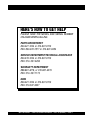
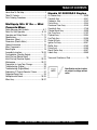
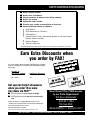
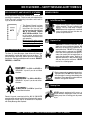
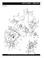
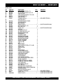
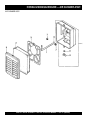
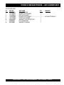
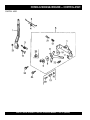
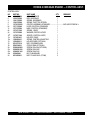
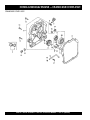
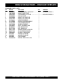
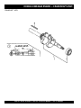
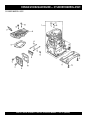
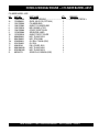
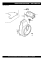
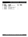
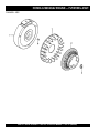
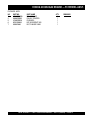
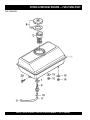
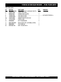
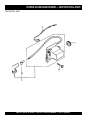
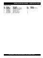
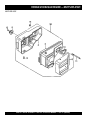
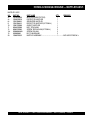
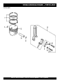
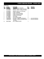
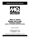
PARTS AND OPERATION MANUAL
© COPYRIGHT 2002, MULTIQUIP INC.
MIX N' GO
MINI CONCRETE MIXER
STEEL DRUM MODELS
MC3SE, MC3H (HONDA)
Revision #0 (09/09/02)
MULTIQUIP INC..
PARTS DEPARTMENT:
18910 WILMINGTON AVE.
800-427-1244
CARSON, CALIFORNIA 90746 FAX: 800-672-7877
SERVICE DEPARTMENT/TECHNICAL ASSISTANCE:
310-537-3700
800-421-1244
800-478-1244
FAX: 310-537-3927
FAX: 310-631-5032
E-mail:[email protected] • www:multiquip.com
Atlanta • Boise • Dallas • Houston • Newark
Montreal, Canada • Manchester, UK
Rio De Janiero, Brazil • Guadalajara, Mexico
HERE'S HOW TO GET HELP
PLEASE HAVE THE MODEL AND SERIAL NUMBER
ON-HAND WHEN CALLING
PARTS DEPARTMENT
800-427-1244 or 310-537-3700
FAX: 800-672-7877 or 310-637-3284
SERVICE DEPARTMENT/TECHNICAL ASSISTANCE
800-478-1244 or 310-537-3700
FAX: 310- 537-4259
WARRANTY DEPARTMENT
888-661-4279, or 310-661-4279
FAX: 310- 537-1173
MAIN
800-421-1244 or 310-537-3700
FAX: 310-537-3927
MIX N' GO MIXER — PARTS & OPERATION MANUAL — REV. #0 (08/09/02) — PAGE 3
TABLE OF CONTENTS
Here's How To Get Help ............................................ 3
Table Of Contents ..................................................... 4
Parts Ordering Procedures ....................................... 5
Multiquip Mix N' Go — Mini
Concrete Mixer
Safety Message Alert Symbols .............................. 6-7
Rules For Safe Operation .................................... 8-10
Operation and Safety Decals ............................. 11-12
Specifications .......................................................... 13
Dimensions (Mixer) ................................................. 14
Dimensions (Electric Motor) .................................... 15
General Information ................................................ 16
Mixer Components .................................................. 17
Basic Engine ........................................................... 18
Assembly Instructions ........................................ 19-20
Pre-Inspection (Gasoline Engine) ........................... 21
Initial Start-up (Electric Motor) ................................ 22
Initial Start-up (Gasoline Engine)....................... 23-24
Maintenance ...................................................... 25-27
Preparation for Long-Term Storage ........................ 28
Troubleshooting (Engine) ........................................ 30
Troubleshooting (Engine/Mixer) .............................. 31
Explanation Of Code In Remarks Column .............. 32
Suggested Spare Parts ........................................... 33
Nameplate and Decals....................................... 34-35
Mixer Assy. ......................................................... 36-37
Honda G100K2QA2 Engine
Air Cleaner Assy. ................................................ 38-39
Camshaft Assy. .................................................. 40-41
Carburetor Assy. ................................................ 42-42
Control Assy. ...................................................... 43-44
Crankcase Cover Assy. ...................................... 45-46
Crankshaft Assy. ................................................ 47-48
Cylinder Barrel Assy. .......................................... 49-50
Fan Cover Assy. ................................................. 51-52
Flywheel Assy..................................................... 53-54
Fuel Tank Assy. .................................................. 55-56
Gasket Kit Assy. ................................................. 57-58
Ignition Coil Assy. ............................................... 60-61
Muffler Assy........................................................ 62-63
Piston Assy. ........................................................ 64-65
Recoil Starter Assy. ............................................ 66-67
Labels Assy. ....................................................... 68-69
Terms and Conditions of Sale ................................. 70
NOTE
Specification and part number
are subject to change without
notice.
PAGE 4 —MIX N' GO MIXER — PARTS & OPERATION MANUAL — REV. #1 (09/09/02)
PARTS ORDERING PROCEDURES
■
■
■
■
■
■
■
Dealer account number
Dealer name and address
Shipping address (if different than billing address)
Return fax number
Applicable model number
Quantity, part number and description of each part
Specify preferred method of shipment:
•
•
•
•
UPS Ground
UPS Second Day or Third Day*
UPS Next Day*
Federal Express Priority One (please provide us with your Federal
Express account number)*
•
•
Airborne Express*
Truck or parcel post
*Normally shipped the same day the order is received, if prior to 2PM west coast time.
Earn Extra Discounts when
you order by FAX!
All parts orders which include complete part numbers
and are received by fax qualify for the following extra
discounts:
Number of
line items ordered
1-9 items
Additional Discount
3%
10+ items**
5%
Get special freight allowances
when you order 10 or more
line items via FAX!**
■ UPS Ground Service at no charge for freight
■ UPS Third Day Service at one-half of actual freight
cost
No other allowances on freight shipped by any other carrier.
**Common nuts, bolts and washers (all items under $1.00 list price)
do not count towards the 10+ line items.
*DISCOUNTS ARE SUBJECT TO CHANGE*
ount
c
s
i
D
Fax
Extra
c USA
i
t
s
e
m
for Do
Only
s
r
e
l
Dea
Now! Direct TOLL-FREE access
to our Parts Department!
Toll-free nationwide:
800-421-1244
Toll-free FAX:
800/6-PARTS-7 • 800-672-7877
Fax order discount and UPS special programs revised June 1, 1995
MIX N' GO MIXER — PARTS & OPERATION MANUAL — REV. #1 (09/09/02) — PAGE 5
MIX N' GO MIXER — SAFETY MESSAGE ALERT SYMBOLS
FOR YOUR SAFETY AND THE SAFETY OF OTHERS!
Safety precautions should be followed at all times when
operating this equipment. Failure to read and understand the
Safety Messages and Operating Instructions could result in
injury to yourself and others.
NOTE
This Owner's Manual has been
developed to provide complete
instructions for the safe and
efficient operation of the Multiquip
MIX N' GO MIXER Models
MC3E, MC3B and MC3H. Refer
to the engine manufacturers
instructions for data relative to its
safe operation.
Before using this mixer, ensure
that the operating individual
has read and understands all
instructions in this manual.
SAFETY MESSAGE ALERT SYMBOLS
The three (3) Safety Messages shown below will inform you
about potential hazards that could injure you or others. The
Safety Messages specifically address the level of exposure to
the operator, and are preceded by one of three words: DANGER,
WARNING, or CAUTION.
DANGER:
You WILL be KILLED or
SERIOUSLY injured if you do not follow
directions.
WARNING: You CAN be KILLED or
SERIOUSLY injured if you do not follow
directions.
HAZARD SYMBOLS
Lethal Exhaust Gases
Engine exhaust gases contain poisonous
carbon monoxide. This gas is colorless and
odorless, and can cause death if inhaled.
NEVER operate this equipment in a confined
area or enclosed structure that does not
provide ample free flow air.
Explosive Fuel
GASOLINE is extremely flammable, and its
vapors can cause an explosion if ignited. DO
NOT start the engine near spilled fuel or
combustible fluids. DO NOT fill the fuel tank
while the engine is running or hot. DO NOT
overfill tank, since spilled fuel could ignite if it
comes into contact with hot engine parts or
sparks from the ignition system. Store fuel in
approved containers, in well-ventilated areas
and away from sparks and flames. NEVER
use fuel as a cleaning agent.
Burn Hazards
Engine components can generate extreme heat.
To prevent burns, DO NOT touch these areas
while the engine is running or immediately after
operations. Never operate the engine with heat
shields or heat guards removed.
Rotating Parts
CAUTION:
You CAN be injured if you
do not follow directions.
Potential hazards associated with the MIX N' GO MIXER
operation will be referenced with Hazard Symbols which appear
throughout this manual, and will be referenced in conjunction
with Safety Message Alert Symbols.
NEVER operate equipment with covers, or
guards removed. Keep fingers, hands, hair and
clothing away from all moving parts to prevent
injury.
PAGE 6 —MIX N' GO MIXER — PARTS & OPERATION MANUAL — REV. #1 (09/09/02)
MIX N' GO MIXER — SAFETY MESSAGE ALERT SYMBOLS
Accidental Starting
Respiratory Hazard
ALWAYS place the engine or electric motor
ON/OFF switch in the OFF position when the
mixer is not in use.
ALWAYS wear approved respiratory
protection.
Equipment Damage Messages
Sight and Hearing hazard
ALWAYS wear approved eye and hearing
protection.
Other important messages are provided throughout this manual
to help prevent damage to your mixer, other property, or the
surrounding environment.
NOTE
This mixer, other property, or the
surrounding environment could
be damaged if you do not follow
instructions.
MIX N' GO MIXER — PARTS & OPERATION MANUAL — REV. #1 (09/09/02) — PAGE 7
RULES FOR SAFE OPERATION
DANGER:
Failure to follow instructions in this manual may
lead to serious injury or even death! This
equipment is to be operated by trained and
qualified personnel only! This equipment is for
industrial use only.
The following safety guidelines should always be used when
operating the Mix N' Go Mixer:
GENERAL SAFETY
■ DO NOT operate or service this equipment before
reading this entire manual.
■ This equipment should not be operated by
persons under 18 years of age.
■ NEVER operate this equipment without proper
protective clothing, shatterproof glasses, steeltoed boots and other protective devices required
by the job.
■ NEVER operate this equipment when not feeling
well due to fatigue, illness or taking medicine.
■ NEVER operate this equipment under the
influence or drugs or alcohol.
■ Whenever necessary, replace nameplate, operation and
safety decals when they become difficult read.
■ ALWAYS check the machine for loosened threads or bolts
before starting.
■ ALWAYS wear proper respiratory (mask) hearing and eye
protection equipment when operating the mixer.
■ NEVER touch the hot exhaust manifold,
muffler or cylinder. Allow these parts to
cool before servicing engine or mixer.
■ High Temperatures – Allow the engine to cool before adding
fuel or performing service and maintenance functions. Contact
with hot components can cause serious burns.
■ The engine of this mixer requires an adequate free flow of
cooling air. NEVER! operate the roller mixer in any enclosed
or narrow area where free flow of the air is restricted. If the air
flow is restricted it will cause
serious damage to the
mixer or engine and may
cause injury to people and
property. Remember the
mixer's engine (gasoline
models only) gives off
DEADLY gases.
■ ALWAYS refuel in a well-ventilated area, away from sparks
and open flames.
■ ALWAYS use extreme caution when working with flammable
liquids. When refueling, stop the engine and allow it to cool.
DO NOT smoke around or near the machine. Fire or explosion
could result from fuel vapors, or if fuel is spilled on a hot
engine.
■ NEVER operate the mixer in an explosive
atmosphere or near combustible
materials. An explosion or fire could result
causing severe bodily harm or even
death.
■ Topping-off to filler port is dangerous, as it tends to spill fuel.
■ Refer to the Engine Owner's Manual for engine technical
questions or information.
■ NEVER use accessories or attachments, which are not
recommended by Multiquip for this equipment. Damage to
the equipment and/or injury to user may result.
■ Manufacturer does not assume responsibility for any accident
due to equipment modifications.
PAGE 8 —MIX N' GO MIXER — PARTS & OPERATION MANUAL — REV. #1 (09/09/02)
RULES FOR SAFE OPERATION
■ NEVER Run engine without air cleaner. Severe engine
damage may occur.
■ ALWAYS read, understand, and follow procedures in
Operator’s Manual before attempting to operate equipment.
■ ALWAYS be sure the operator is familiar with proper safety
precautions and operations techniques before using roller.
■ ALWAYS store equipment properly when it is not being used.
Equipment should be stored in a clean, dry location out of the
reach of children.
■ NEVER leave the mixer unattended, turn off engine or electric
motor when unattended.
■ CAUTION must always be observed while servicing this mixer.
Rotating parts can cause injury if contacted.
■ Unauthorized equipment modifications will void all
warranties.
■ Ensure that any trailing cable is protected against damage
and not liable to be tripped over or trapped underneath the
mixer.
■ Ensure any extention cables must be no longer than 30 meters
(100 feet) in length and that the wire section is 2.5 mm 2.
■ High Temperatures – Always stop engine and allow the
engine to cool before adding fuel, oil or performing service
and maintenance functions. Contact with hot components can
cause serious burns.
■ NEVER disconnect any "emergency or safety devices".
These devices are intended for operator safety. Disconnection
of these devices can cause severe injury, bodily harm or even
death! Disconnection of any of these devices will void all
warranties.
■ If mixer is equipped with an electric motor, operate only at
120 VAC, 60 Hz.
■ Make sure the OFF/ON power switch is always in the OFF
position before inserting the mixer's power plug into an AC
receptacle (electric model only).
Maintenance Safety
■ NEVER lubricate components or attempt service on a running
machine.
■ ALWAYS allow the machine a proper amount of time to cool
before servicing.
■ Keep the machinery in proper running condition.
■ DO NOT allow extension cord to come into contact with water
or fluids.
■ Fix damage to the machine immediately and always replace
broken parts, or missing decals.
■ DO NOT expose power tools to rain or wet conditions.
■ Dispose of hazardous waste properly. Examples of potentially
hazardous waste are used motor oil, fuel and fuel filters.
■ This mixer is intended for the production of concrete, mortar
and plaster. Mixer must be used only for its intended purpose.
■ This mixer is not suitable for the mixing of flammable or
explosive substances.
■ NEVER operate the mixer in an explosive atmosphere.
■ DO NOT use food or plastic containers to dispose of
hazardous waste.
■ DO NOT pour waste, oil or fuel directly onto the ground,
down a drain or into any water source.
■ Before starting the mixer, check that all guards are in position
and correctly fitted.
■ DO NOT tip mixer onto drum mouth when the motor is running.
■ Keep area around the mixer clear of obstructions which
could cause persons to fall onto moving parts.
■ ALWAYS ensure mixer is on level ground before mixing.
■ Become familiar with the controls of the machine before
operating.
■ ALWAYS replace any worn or damaged warning decals.
■ Ensure the drum is rotating while filling and emptying the
drum.
■ DO NOT use mixer as a wheel barrel.
■ ALWAYS disconnect AC power plug from power source
before moving mixer (electric model only).
MIX N' GO MIXER — PARTS & OPERATION MANUAL — REV. #1 (09/09/02) — PAGE 9
RULES FOR SAFE OPERATION
Emergencies
■ ALWAYS know the location of the nearest fire extinguisher.
■ ALWAYS know the location of the nearest first aid kit.
■ In emergencies always know the location of the
nearest phone or keep a phone on the job site.
Also know the phone numbers of the nearest
ambulance, doctor and fire department. This
information will be invaluable in the case of an
emergency.
PAGE 10 —MIX N' GO MIXER — PARTS & OPERATION MANUAL — REV. #1 (09/09/02)
OPERATION AND SAFETY DECALS
Machine Safety Decals
The Mix N' Go mixer is equipped with a number of safety decals. These decals are provided for operator safety and maintenance
information. The illustration below and on the next page shows these decals as they appear on the machine. Should any of these
decals become unreadable, replacements can be obtained from your dealer.
WARNING!
ALARMA!
AVERTISSEMENT!
ENGLISH - WARNING! TO REDUCE THE RISK OF INJURY, USER MUST READ AND UNDERSTAND INSTRUCTION MANUAL
ESPAÑOL - ATENCION! PARA REDUCIR EL RIESGO DEL LESIONES EL USUARIO DEBE LEER Y ENTENDER EL MANUAL DE INSTRUCCIONES
FRANÇAIS - ATTENTION! AFIN DE DIMINUER LE RISQUE DE BLESSURES L’UTILISATEUR DOIT LIRE ET COMPRENDRE CE MANUEL D’ INSTRUCTIONS
DCL251
P/N DCL251
TBD
MIX N' GO MIXER — PARTS & OPERATION MANUAL — REV. #1 (09/09/02) — PAGE 11
OPERATION AND SAFETY DECALS
WARNING!
ADVERTENCIA!
AVERTISSEMENT!
GASOLINE ENGINE
Make sure engine is turned off and spark plug wire is
disconnected before cleaning mixer.
MÁQUINAS DE GASOLINA
Asegure que la máquina este apagada y el alambre de la bujía
este desconectado antes de empezar a limpiar la mezcladora.
1. Lisez le manual d’ utilisation avant d’ utiliser le le malaxeur.
2. Seul un personnel qualifié peut être authorisé à se trouver à proximité
du malaxeur quand il est en opération.
3. Assurez vous que tous les dispositifs de sécurité sont en place avant
de mettre le malaxeur en marche.
4. Gardez les mains et doigts loin de toute piè en mouvement.
5. NE LAISSEZ jamais le malaxeur sans surveillance quand il est en
opération.
6. VEUILLEZ toujours vérifier la courroie avant de mettre le malaxeur
en marche.
MOTEUR À ESSENCE
Assurez vous que le moteur est arrêté et que le fil de la bougie est
débranché avant de nettoyer le malaxeur.
DO NOT operate mixer in an enclosed area, proper
ventilation is required.
NO encienda la mezcladora en una área cerrada; es necesario
estar en una área que tenga apropiada ventilación.
N’ UTILISEZ pas le malaxeur dans un endroit fermé, il est nécessaire
de travailler dans un endroit avec une bonne aération.
ALWAYS stop the engine and allow engine to cool before
adding fuel or oil.
SIEMPRE apague la máquina y permita que se enfrie antes de
ponerle gasolina o aceite.
VEUILLEZ toujours vé la courroie avant de mettre le malaxeur en
marche.
ALWAYS check fuel, oil and air filter before starting engine.
SIEMPRE revise la gasolina, aceite, y el filtro del air antes de
encender la máquina.
VÉRIFIEZ toujours le niveau d’essence et d’huile ainsi que le filtre à
air avant de mettre le moteur en marche.
ELECTRIC MOTOR
Make sure power cord has been disconnected from power
source before cleaning mixer.
MOTOR ELÉCTRICO
Asegúrese que el cable de corriente esté de empezar a limpiar
la mezcladora.
Este motor elétrico está solamente capacitado para corriente
alterna de 115 voltios.
SIEMPRE use el tamaño de extensiones de alambre indicado
como muestra el diagrama abajo:
1. Read owner’s manual before operating mixer.
2. Keep unauthorized and untrained people away
from mixer during operation.
3. Make sure all safety devices (guards) are in place
before mixer is started.
4. Keep hands and fingers away from moving objects.
5. NEVER leave mixer unattended when operating.
6. ALWAYS check V-belt before starting mixer.
1. Lea el manual de operació antes de usar la mezcladora.
2. Mantenga personas que no estén autorizadas o capacitadas
alejades de la mezcladora durante el funcionamiento de la
máquina.
3. Asegúreseque todos los aparatos de seguridad estén
trabajando apropiadamente antes de usar la mezcladora.
4. Mantenga las monos y dedos alejados de objetos en moviminto.
5. NUNCA se aleje de la mezclaora mientras ésta, este trabajando!
6. SIEMPRE inspeccione la banda antes de encender la mezcladora.
This electric motor is for 115 VAC operation only.
ALWAYS use an extension cord of proper size, see chart
below:
No. 10 Wire
No. 8 Wire
75 feet
100 feet
50 feet
(15.24 meters) (22.86 meters) (30.48 meters)
No. 6 Wire
200 feet
(60.96 meters)
Alambre
Numéro 12
Alambre
Numéro 10
Alambre
Numéro 8
MOTOR
ELÉCTRICO
MOTEUR
ÉLECTRIQUE
TAILLE DE LA RALLONGE
Alambre
Numéro 6
200 pies
75 pies
100 pies
50 pies
(15.24 metros) (22.86 metros) (30.48 metros) (60.96 metros)
REMOVE BOLT AND FILL
WITH EP. 90 GEAR OIL
ELECTRIC
MOTOR
Ce moteur électrique à été conçu pour opération à 115 volts seulement.
Il faut toujours utiliser une rallonge de taille appropriée, veuillez s’il vous
référer au diagramme suivant:
TAMAÑO DE EXTENSIÓN
EXTENSION CORD SIZE
No. 12 Wire
MOTEUR ÉLECTRIQUE
Assures vous toujours que le cable a été débranché de la prise de
courant avant de nettoyer le malaxeur.
Cable
Numéro 12
MOTOR
ELÉCTRICO
MOTEUR
ÉLECTRIQUE
ÔTEZ LE BOULON ET
REMPLISSEZ AVEC DE I’HUILE
EP. 90 À ENGRENAGES
Cable
Numéro 8
Cable
Numéro 6
50 pieds
50 pieds
50 pieds
50 pieds
(15.24 métres) (15.24 métres) (15.24 métres) (15.24 métres)
ELECTRIC
MOTOR
REMOVER EL TORÑILLO Y
LLENAR CON ACEITE DE
ENGRNAJE EP. 90
Cable
Numéro 10
NEVER! OPERATE MIXER WITH
V-BELT COVER REMOVED.
NUNCA! MANEJE LA MEZCLADORA
SIN LA COBERTURA DE BANDA-V
REMOVIDA.
N’ UTILISEZ! JAMAIS LE MALAXEUR
SANS LE COUVERCLE DE LA COURROIE.
CHECK DAILY
REVISAR DIARIO
VÉRIFIEZ QUOTIDIENNEMENT
DCL250
P/N DCL250
PAGE 12 —MIX N' GO MIXER — PARTS & OPERATION MANUAL — REV. #1 (09/09/02)
MIX N' GO MIXER — SPECIFICATIONS
Table 1. Specifications (Engine & Electric Motor)
Model
HONDA G100K2QA2
BALDOR 17LYE304
4-stroke, Side valve, Single Cylinder
3/4 HP, 120 VAC, Single
Phase Electric Motor
Bore X Stroke
20.5 in. X 18.1 in.
(52 mm x 46 mm)
N/A
Displacement
6.0 cu. in. (98 cc)
N/A
2.5 H.P. at 3,600 R.P.M.
3/4 H.P./3,450 RPM
Standard Idle Speed
1,400 ± 100 R.P.M.
N/A
Fuel Tank Capacity
Approx. 0.37 U.S. Gallons
(1.4 Liters)
N/A
Unleaded Gasoline
N/A
0.48 U.S. Quar ts (0.45 Liters)
N/A
Centrifugal Fly-weight Type
N/A
Recoil Star t
N/A
10.8 x 10.6 X 13.6 in.
(275 X 270 X 345 mm)
11.75 x 6.0 X 8.0 in.
(298 X 152 X 203 mm)
19.2 lbs (8.7 Kg.)
Approx. 12 lbs. (5.4 Kg.)
Type
Max Output
Engine/Electric Motor
Fuel
Lube Oil Capacity
Speed Control Method
Star ting Method
Dimensions (L x W x H)
Dry Net Weight
Table 2. Mix N' Go Mixer Specifications
Height
34 in. (863.6 mm)
Width
23-5/8 in. (584.2 mm)
Length
48-1/2 in. (1,219.2 mm)
Stand Weight
35 lbs. (15.9 Kg)
Maximum Drum Capacity
4.5 cu. ft. (0.13 m3)
Maximum Mixing Capacity (1/2 bag)
3.0 cu. ft. (0.08 m3)
Unladen Weight - Electric Motor
129 lbs. (58.5 Kg)
Unladen Weight - Gasoline Engine
138 lbs. (62.6 Kg)
MIX N' GO MIXER — PARTS & OPERATION MANUAL — REV. #1 (09/09/02) — PAGE 13
MIX N' GO MIXER — DIMENSIONS (MIXER)
Figure 1. Mix N' Go
Mixer Dimensions
PAGE 14 —MIX N' GO MIXER — PARTS & OPERATION MANUAL — REV. #1 (09/09/02)
MIX N' GO MIXER — DIMENSIONS (ELECTRIC MOTOR)
Figure 2. Electric Motor
MIX N' GO MIXER — PARTS & OPERATION MANUAL — REV. #1 (09/09/02) — PAGE 15
MIX N' GO MIXER — GENERAL INFORMATION
APPLICATION
PORTABLE GENERATORS
This mixer is only intended for the production of concrete,
mortar and plaster. The mixer must be used for its intended
purposes and is not suitable for the mixing of flammable or
explosive substances. The mixer must not be used in an
explosive atmosphere.
POWER PLANTS
When using a portable generator it must have a minimum
output of 2.5 kw and be continuous rated.
This portable mixer is powered by either a Honda G100K2,
4-stroke, side valve, single cylinder, gasoline engine rated
at 2.5 hp @3,600 rpm. or a 0.75 hp electric motor.
DRUM ASSEMBLY
The drum is instantly removable by unscrewing counterclockwise. When inserting drum onto gearbox shaft, make sure
that drum is fully screwed onto shoulder or threads may be
damaged. Use extreme care when screwing on the drum,
spinning drum onto the gearbox shaft too fast may damage
gearbox.
GEARBOX
The gearbox oil level has been preset at the factory prior to
shipping. Before inspecting the gearbox oil level (Figures 30
and 31), make sure the gearbox is cold before removing the
filler plug. Fill up with EP90. or similar gear oil.
TRANSPORTING THE MIXER
Use a ramp (Figure 3) to load and unload the mixer from the
transport vehicle. Never drop the mixer onto the ground; damage
to the mixer could result.
ELECTRICAL
If mixer is equipped with an electric motor, make sure that
the power being supplied to the motor corresponds to the
voltage rating label on the motor. Supplying the wrong voltage
to the electric motor will cause severe electrical damage to
the motor.
Always make sure that OFF/ON switch on the electric motor
is in the OFF position before applying power.
It is strongly recommended that when plugging in the
mixer's power cord into a receptacle, that a G.F.C.I. (Ground
Fault Current Interrupter) receptacle be used.
EXTENSION CABLES
The extension cable should be a 3-wire configuration that
includes a ground wire that conforms to UL code. The wire
cross section must be a minimum of 2.5 mm2 . Choose an
extension cord of adequate current carrying as Reference in
Table 5. Remember distance affects the wire size of the
extension cable.
Ensure that the extension cable is carefully laid out avoiding wet areas, sharp edges and locations where vehicles
might run over it. Avoid allowing the extension cable to be
trapped underneath the mixer.
Unroll the extension cable fully or it will overheat and could
catch fire. Make sure that all extension cable connections
are dry and safe. Replace any defective or badly worn extension cable immediately.
Figure 3. Mixer Loading
PAGE 16 —MIX N' GO MIXER — PARTS & OPERATION MANUAL — REV. #1 (09/09/02)
MIX N' GO MIXER — MIXER COMPONENTS
Figure 4 shows the basic components of the Mix N' Go
Mixer.
Figure 4. Mixer Components
Table 3. MIXING HINTS
BATCH QUANTITIES
APPLICATIONS
MIX
RATIOS
SAND
APPROX. BATCH
OUTPUT
CEMENT 112 lbs.
(50 Kgs.)
Bag
STONE
CU. FT.
LTR
CU. FT.
LTR
CU. FT.
LTR
Most Ordinary
1:2:4
1/2 BAG
1-1/4
35
2-1/2
71
3
85
Foundations
1:3:6
1/3 BAG
1-1/4
35
2-1/2
71
2-3/4
78
Rough Mass
Concrete
1:4:8
1/4 BAG
1-1/4
35
2-1/2
71
2-3/4
78
1:1-1/2:3
2/3 BAG
1-1/4
35
3
71
3
85
Watertight Floors,
Tanks, Pits, Etc.
MIX N' GO MIXER — PARTS & OPERATION MANUAL — REV. #1 (09/09/02) — PAGE 17
MIX N' GO MIXER — BASIC ENGINE
Figure 5. Engine Controls and Components
INITIAL SERVICING
The engine (Figure 5) must be checked for proper lubrication and
filled with fuel prior to operation. Refer to the manufacturers engine
manual for instructions and details of operation and servicing. The
engine shown above is a HONDA engine, operation for other
types of engines may vary somewhat.
1.
7.
Air Cleaner – Prevents dirt and other debris from entering
the fuel system. Remove wing-nut on top of air filter
cannister to gain access to filter element.
8.
Choke Lever – Used in the starting of a cold engine, or in
cold weather conditions. The choke enriches the fuel
mixture.
Fuel Filler Cap – Remove this cap to add unleaded
gasoline to the fuel tank. Make sure cap is tightened
securely. DO NOT over fill.
Operating the engine without an air
filter, with a damaged air filter, or a
filter in need of replacement will
allow dirt to enter the engine,
causing rapid engine wear.
NOTE
DANGER
Adding fuel to the tank should be done only when
the engine is stopped and has had an opportunity to
cool down. In the event of a fuel spill, DO NOT
attempt to start the engine until the fuel residue has been completely
wiped up, and the area surrounding the engine is dry.
9.
Spark Plug – Provides spark to the ignition system. Set
spark plug gap to 0.6 - 0.7 mm (0.024 - 0.028 inch) Clean
spark plug once a week.
10. Muffler – Used to reduce noise and emissions.
2.
Fuel Tank – Holds unleaded gasoline. For additional
information refer to engine owner's manual.
3.
Engine ON/OFF Switch – ON position permits engine
starting, OFF position stops engine operation.
4.
Recoil Starter (pull rope) – Manual-starting method. Pull
the starter grip until resistance is felt, then pull briskly and
smoothly.
5.
Throttle Lever – Used to adjust engine RPM speed (lever
advanced forward SLOW, lever back toward operator
FAST).
11. Oil Drain Plug – Remove this plug to remove oil from the
engine's crankcase.
6.
Fuel Valve Lever – OPEN to let fuel flow, CLOSE to stop
the flow of fuel.
12. Dipstick/Oil Filler Cap – Remove this cap to determine if
the engine oil is low. Add oil through this filler port as
recommended in Table 4.
WARNING
Engine components can generate extreme heat.
To prevent burns, DO NOT touch these areas
while the engine is running or immediately after
operating. NEVER operate the engine with the
muffler removed.
PAGE 18 —MIX N' GO MIXER — PARTS & OPERATION MANUAL — REV. #1 (09/09/02)
MIX N' GO MIXER — ASSEMBLY INSTRUCTIONS
Assembly
1. Remove the mixer drum and associated components from
the packing container (Figure 6). Match the components
against the parts list to make sure that they are all accounted
for.
Figure 6. Packing Container
2. Place the mixer frame on a secure level surface, and attach
the top cover as shown in Figure 7.
Figure 8. Mixing Drum Placement
4. Place the two halves of the support stand together (Figure 9).
The left support stand fits into the center boss on the right
support stand.
5. Insert the adapter pin through bosses as shown in Figure 9.
Once the adapter pin has been inserted and aligned, insert
the locking pin. Place the round part of the locking pin over
the bottom section of the adapter pin.
Figure 7. Top Cover Placement
3. Fit the mixing drum onto gearbox shaft as shown in Figure
8. Rotate drum in a clockwise direction, make sure the drum
fits right up to the shoulder on the gearbox shaft.
CAUTION
DO NOT spin the drum on fast, as this may
damage the gearbox.
Figure 9. Support Stand
MIX N' GO MIXER — PARTS & OPERATION MANUAL — REV. #1 (09/09/02) — PAGE 19
MIX N' GO MIXER — ASSEMBLY INSTRUCTIONS
6. Tip mixer onto mouth as shown in Figure 10, and insert
support stand into frame swivel point.
9. Before attempting to lift mixer, locate the frame locking clip.
Attach the locking clip as shown in Figure 12.This will prevent
the mixing drum from moving when the mixer is positioned
in an upright position.
Figure 12. Frame Locking Clip
10. DO NOT tilt the mixer on a wet, smooth or slippery surface.
Figure 10. Attaching Support Stand
7. Remove both wheels and wheel retainers from the packing
container.
8. Place one wheel on each side of the mixer's axle as shown
in Figure 11. Position wheel retainer over axle to secure
wheel in place. Use a rubber mallet when striking wheel
retainer.
Figure 13. Slippery or Wet Surfaces
11. Once the stand has been assembled, and the locking clip has
been secured, begin tilting the mixer to an upright position.
Remember always tilt from the front of the mixer as shown
in Figure 14.
Figure 11. Wheels and Wheel Retainers
Figure 14. Tilting Mixer to Upright Position
PAGE 20 —MIX N' GO MIXER — PARTS & OPERATION MANUAL — REV. #1 (09/09/02)
MIX N' GO MIXER — PRE-INSPECTION (GASOLINE ENGINE)
CAUTION
NEVER operate the mixer in
a confined area or enclosed
area structure that does not
provide ample free flow of air.
3. Insert and remove the dipstick without screwing it into the filler
neck. Check the oil level shown on the dipstick.
4. If the oil level is low (Figure 16), fill to the edge of the oil filler
hole with the recommended oil type (Table 4). Maximum oil
capacity is 0.48 quarts (.45 liters)
ALWAYS wear approved eye and hearing
protection before operating the mixer.
NEVER place hands inside drum while the
engine is running. ALWAYS shut the engine
down before performing any kind of
maintenance service on the mixer.
Figure 16. Engine Oil Dipstick (Oil Level)
Table 4. Oil Type
Before Starting
1.
Read safety instructions at the beginning of manual.
2.
Clean the mixer, removing dirt and dust, particularly the
engine cooling air inlet, carburetor and air cleaner.
3.
Check the air filter for dirt and dust. If air filter is dirty, replace
air filter with a new one as required.
4.
Check carburetor for external dirt and dust. Clean with dry
compressed air.
5.
Check fastening nuts and bolts for tightness.
Engine Oil Check
1.
To check the engine oil level, place the mixer on secure
level ground with the engine stopped.
2.
Remove the filler dipstick from the engine oil filler hole
(Figure 15) and wipe clean.
Season
Temperature
Oil Type
Summer
25°C or Higher
SAE 10W-30
Spring/Fall
25°C~10°C
SAE 10W-30/20
Winter
0°C or Lower
SAE 10W-10
Explosive Fuel
Fuel Check
Motor fuels are highly flammable and can be dangerous if
mishandled. DO NOT smoke while refueling. DO NOT attempt
to refuel the mixer if the engine is hot! or running.
1. Remove the gasoline cap located on top of fuel tank.
2. Visually inspect to see if fuel level is low. If fuel is low, replenish
with unleaded fuel.
3. When refueling, be sure to use a strainer for filtration. DO
NOT top-off fuel. Wipe up any spilled fuel.
V-Belt Check
A worn or damaged V-belt can adversely affect the performance
of the trowel. If a V-belt is defective or worn simply replace the Vbelt as outlined in the maintenance section of this manual.
Figure 15. Engine Oil Dipstick (Removal)
MIX N' GO MIXER — PARTS & OPERATION MANUAL — REV. #1 (09/09/02) — PAGE 21
MIX N' GO MIXER — INITIAL START-UP (ELECTRIC MOTOR)
5. Plug the other end of the extension cord into a 120 VAC
G.F.C.I. protected receptacle. Remember the power requirements for this electric motor is 120 VAC, 60 Hz. The use of
any other input voltage will severely damage the motor.
Initial Start-up Instructions (Electric Motor)
Starting
CAUTION:
DO NOT attempt to operate the mixer until
the Safety, General Information and
Inspection sections have been read and
understood.
1. Before starting, make sure mixer is positioned on a secure
flat surface to prevent tipping.
2. Use an extension cord (see Table 5) of adequate current
carrying capacity, insert the electric motor's power plug into
one end of the extension cord.
3. NEVER! use a worn or frayed extension cord.
4. NEVER! operate mixer with V-belt cover removed.
WARNING:
ALWAYS read the label on the electric motor
before applying power. The label will indicate the
proper power requirements for the motor.
Remember the use of any other input voltage will
severely damage the motor.
WARNING:
To prevent tripping (Figure 18) of both the mixer
and personnel, position the extension cord so that
it lays flat and is not curled underneath the mixer.
Table 5. Extension Cord Size
No. 12 Wire
No. 10 Wire
50 (feet)
(15.24 meters)
No. 8 Wire
No. 6 Wire
75 (feet)
100 (feet)
200 (feet)
(22.86 meters (30.48 meters (60.96 meters
Figure 18. Mixer (Tripping)
DANGER
NEVER! touch the power cord (Figure 17)
with wet hands or while standing in water
when it is connected to a power source. The
possibly exists of electrical shock
(electrocution) even death. NEVER! spray
water directly on the electric motor.
6. The drum should be rotating allowing the mixing process to
begin. Use a shovel (Figure 19) to place the cement mix
inside the drum, add water as required. Be careful to only
place the tip of the shovel inside the drum. Placing the shovel
all the way inside the drum will cause the shovel to strike the
blades. This condition will make the shovel rotate, and could
cause injury to personnel.
WET
HANDS
POWER
CORD
(POWER ON)
Figure 17. Extension Cord (Wet Hands)
Figure 19. Mixing Drum (Placing cement Mix))
6. See Table 3 for mixing hints. NEVER! place hands inside the
drum while the drum is rotating.
PAGE 22 —MIX N' GO MIXER — PARTS & OPERATION MANUAL — REV. #1 (09/09/02)
MIX N' GO MIXER — INITIAL START-UP (GASOLINE ENGINE)
DO NOT attempt to operate the mixer until
the Safety, General Information and
Inspection sections of this manual have
been read and thoroughly understood.
3. Place the choke lever (Figure 22) in the "OPEN " position
if starting a cold engine.
This section is intended to assist the operator with the initial
start-up of the walk-behind trowel. It is extremely important that
this section be read carefully before attempting to use the trowel
in the field.
Starting the Engine (HONDA engine)
1. Place the engine fuel valve lever (Figure 20) to the "ON"
position.
Figure 22. Engine Choke Lever (Open)
4. Place the choke lever (Figure 23) in the "CLOSED " position
if starting a warm engine or the temperature is warm.
Figure 20. Engine Fuel Valve Lever (ON Position)
2. Place the trowel's throttle lever (Figure 21) to the "IDLE"
position.
Figure 23. Engine Choke Lever (Closed)
5. Place the engine ON/OFF switch (Figure 24) in the "ON "
position.
Figure 21. Throttle Lever (Idle Position)
Figure 24. Engine ON/OFF Switch (ON Position)
MIX N' GO MIXER — PARTS & OPERATION MANUAL — REV. #1 (09/09/02) — PAGE 23
MIX N' GO MIXER — INITIAL START-UP (GASOLINE ENGINE)
6. Grasp the starter grip (Figure 25) and slowly pull it out. The
resistance becomes the hardest at a certain position, corresponding to the compression point. Pull the starter grip briskly
and smoothly for starting.
2. After the engine cools, turn the engine ON/OFF switch to the
“OFF” position (Figure 28 ).
Figure 25. Starter Grip
7. If the engine has started, slowly return the choke lever
(Figure 23 ) to the CLOSED position. If the engine has not
started repeat steps 1 through 6.
Figure 28. Engine ON/OFF Switch (OFF Position)
3. Close the fuel shut- off valve (Figure 29) by moving the fuel
valve lever to the OFF position.
8. Before the mixer is placed into operation, run the engine for
several minutes. Check for fuel leaks, and noises that would
associate with a lose V-belt cover or component.
9. To begin mixing, place the throttle lever (Figure 26) in the
"RUN" position
Figure 29. Fuel Valve Lever (OFF Position)
Figure 26. Throttle Lever (Run Position)
Emergency Showdown
1. Move the throttle lever quickly to the IDLE position, and turn
the engine ON/OFF switch to the OFF position.
Stopping The Engine
Normal Shutdown
1. Move the throttle lever to the IDLE position (Figure 27) and
run the engine for three minutes at low speed.
Figure 27. Throttle Lever (Idle Position)
PAGE 24 —MIX N' GO MIXER — PARTS & OPERATION MANUAL — REV. #1 (09/09/02)
MIX N' GO MIXER — MAINTENANCE
Maintenance
5. Insert oil filler plug and tighten.
Gearbox Oil Check
1. Position the mixer on a level surface and place a support block
under the front of the mixer frame as shown in Figure 30.This
will level the mixer.
2. NEVER! check the gearbox oil level with the mixer tilted up or
down. ALWAYS check the gearbox oil level with the mixer in a
level position.
Figure 31. Gearbox Oil Level Check
V-Belt Check
1. To adjust V-belts, remove V-belt cover and loosen the main
motor mount bolts, raise electric motor and retighten bolts.
Belt tension should be adjusted so that the maximum deflection is approximately 3/8 inch (10 mm).
2. Replace V-belt cover.
Figure 30. Mixer Positioning (Gearbox Oil Level)
CAUTION :
Check the gearbox oil level monthly
before operating mixer. Low oil level or no
oil will severely damage gearbox.
3. Before inspecting the gearbox oil level, make sure the gearbox
is cold before removing the filler plug. Hot! oil can burn skin and
cause injury. Let oil cool before checking.
4. Remove gearbox oil filler plug (Figure 31) and fill with EP90 or
similar gear oil to the level of the filler plug. Replace gearbox oil
every 3,000 hours. Gerabox oil capacity is 8-10 ounces.
Gerarbox Removal
1. Remove drum by turning counter-clockwise to release from
gearbox shaft.
2. Remove pulley, remember the nut securing the pulley is lefthand threaded. Remove circlip, and draw out shaft.
3. Remove the 5 bolts securing rear plate.
4. Reassemble in reverse order, taking care to ensure gear teeth
are meshed correctly.
MIX N' GO MIXER — PARTS & OPERATION MANUAL — REV. #1 (09/09/02) — PAGE 25
MIX N' GO MIXER — MAINTENANCE (GASOLINE ENGINE)
Table 6. Engine Maintenance Schedule
DESCRIPTION (3)
OPERATION
BEFORE
CHECK
X
FIRST
EVERY
MONTH 3 MONTHS
OR
OR
10 HRS. 25 HRS.
EVERY
6 MONTHS
OR
50 HRS.
EVERY
YEAR
OR
100 HRS.
EVERY
2 Y E ARS
OR
2 0 0 HRS .
Engine Oil
CHANGE
CHECK
X
X
Air Cleaner
CHANGE
All Nuts & Bolts
Re-tighten If
Necessary
X (1)
X
CHECK-CLEAN
X
Spark Plug
REPLACE
X
Cooling Fins
CHECK
X
Spark Arrester
CLEAN
X
Fuel Tank
CLEAN
X
Fuel Filter
CHECK
X
Idle Speed
CHECK-ADJUST
X (2)
Valve Clearance
CHECK-ADJUST
Fuel lines
CHECK
X (2)
Every 2 years (replace if necessary) (2)
(1) Service more frequently when used in DUSTY areas.
(2) These items should be serviced by your servic dealer, unless you have the proper tools and are mechanically
proficient. Refer to the HONDA shop Manual for service procedures
(3) For commercial use, log hours of operation to determine proper maintenance intervals.
NOTE
Reference manufacturer engine
manual for specific servicing
instructions.
PAGE 26 —MIX N' GO MIXER — PARTS & OPERATION MANUAL — REV. #1 (09/09/02)
MIX N' GO MIXER — MAINTENANCE (GASOLINE ENGINE)
DANGER :
Maintenance
Perform the scheduled maintenance procedures as definded by
Table 6 and below:
DAILY
■ Thoroughly remove dirt and oil from the engine and control
area. Clean or replace the air cleaner elements as necessary.
Check and retighten all fasteners as necessary. Check the
gearbox for oil leaks. Repair or replace as needed.
WEEKLY
■ Remove the fuel filter cap and clean the inside of the fuel
tank.
■ Remove or clean the filter at the bottom of the tank.
DO NOT use gasoline as a cleaning solvent,
because that would create a risk of fire or
explosion.
ENGINE AIR CLEANER
1. Remove the air cleaner cover and foam filter element as
shown in Figure 34.
2. Clean foam element in warm, soapy water or nonflammable
solvent. Rinse and dry thoroughly. Dip the element in clean
engine oil and completely squeeze out the excess oil from the
element before installing.
■ Remove and clean the spark plug (Figure 32), then adjust
the spark gap to 0.024 ~0.028 inch (0.6~0.7 mm). This unit
has electronic ignition, which requires no adjustments.
Figure 32. Spark Plug Gap
ENGINE OIL
1. Drain the engine oil when the oil is warm as shown in
Figure 33.
2. Remove the oil drain bolt and sealing washer and allow
the oil to drain into a suitable container.
Figure 34. Engine Air Cleaner
3. Replace engine oil with recommended type oil as listed
in Table 4. Engine oil capacity is .48 quarts (0.45 liters).
DO NOT overfill.
4. Install drain bolt with sealing washer and tighten securly.
Figure 33. Engine Oil (Draining)
MIX N' GO MIXER — PARTS & OPERATION MANUAL — REV. #1 (09/09/02) — PAGE 27
MIX N' GO MIXER — PREPARATION FOR LONG -TERM STORAGE
Mixer Storage
For storage of the mixer for over 30 days, the following is
recommended:
z Drain the fuel tank completely, or add STA-BIL to the
fuel.
z Run the engine until the fuel is completely consumed.
z Completely drain used oil from the engine crankcase
and fill with fresh clean oil, then follow the procedures
described in the engine manual for engine storage.
z Clean the entire mixer and engine compartment.
z Cover the mixer and place it a clean dry area, that is
protected from harsh elements.
PAGE 28 —MIX N' GO MIXER — PARTS & OPERATION MANUAL — REV. #1 (09/09/02)
NOTE PAGE
MIX N' GO MIXER — PARTS & OPERATION MANUAL — REV. #1 (09/09/02) — PAGE 29
MIX N' GO MIXER — TROUBLESHOOTING (ENGINE)
TABLE 7. ENGINE TROUBLESHOOTING
SYMPTOM
POSSIBLE PROBLEM
SOLUTION
Difficult to start
Fuel is available but spark plug
will not ignite. (Power available
at high tension cable).
Fuel is available but spark plug
will not ignite. (Power NOT
available at high tension cable).
Fuel is available and spark plug
ignites (compression normal).
Fuel is available and spark plug
ignites (compression low ).
Ignition plug being bridge?
Check ignition system.
Carbon deposit at ignition?
Clean or replace ignition.
Shor t circuit due to defective
insulators?
Replace insulators.
Improper spark gap?
Set spark plug gap to the correct gap.
Shor t circuit at stop switch?
Check stop switch circuit. Replace stop switch if defective.
Ignition coil defective?
Replace ignition coil.
Muffler clogged with carbon
deposits?
Clean or replace muffler.
Fuel in use inadequate (water,
dust)?
Flush fuel sytem and replace with fresh fuel.
Air Cleaner clogged?
Clean or replace air cleaner.
Defective cylinder head gasket?
Tighten cylinder head bolts or replace head gasket.
Cylinder worn?
Replace cylinder.
Spark plug loose?
Tighen spark plug.
Operation not satisfactory
Air cleaner clogged?
Not enough power available
(compression normal, no missfiring).
Not enough power available
(compression normal, missfiring).
Engine overheats.
Air in fuel line?
Bleed (remove air) from fuel line.
Fuel level in carbureator float
chamber improper?
Adjust carbureator float
Carbon deposits in cylinder?
Clean or replace cylinder
Ignition coil defective?
Flush fuel sytem and replace with fresh fuel.
Ignition plug often shor ts?
Replace ignition wires, clean ignition.
Fuel in use inadequate (water,
dust)?
Flush fuel sytem and replace with fresh fuel.
Excessive carbon depostion in
combustion chamber?
Clean or replace crankcase.
Exhaust or muffler clogged with
carbon.
Clean or replace muffler.
Spark plug heat value incorrect?
Replace spark plug with correct type spark plug.
PAGE 30 —MIX N' GO MIXER — PARTS & OPERATION MANUAL — REV. #1 (09/09/02)
MIX N' GO MIXER — TROUBLESHOOTING (ENGINE/MIXER)
TABLE 7. ENGINE TROUBLESHOOTING (Continued)
SYMPTOM
POSSIBLE PROBLEM
SOLUTION
Operation not satisfactory
Rotational speed fluctuates.
Recoil star ter not working
properly.
Governor adjustment improper?
Adjust governor to correct lever.
Governor spring defective?
Clean or replace ignition.
Fuel flow erratic?
Check fuel line.
Air taken in through suction
line?
Check suction line.
Dust in rotating par t?
Clean recoil star ter assembly.
Spring spring failure?
Replace sprial spring.
TABLE 8. MIXER TROUBLESHOOTING
SYMPTOM
Drum rotates rough.
Drum does not rotate at all.
POSSIBLE PROBLEM
SOLUTION
Defective gearbox?
Check that the gears and bearings are not wor n . Replace as
necessary.
Worn V-belt?
Replace V-belt.
Loose pulley?
Tighten or replace pulley.
Incorrect or no voltage being
supplied to electric motor?
Check that the electric motor has the correct supply voltage.
Power to electric motor?
Inspect power source and extension cord. Push reset button on
electric motor.
Fuel?
Check level of fuel in fuel tank. Add fuel if necessary. Make sure
fuel is being supplied to the engine. Check to ensure that the fuel
filter is not clogged.
Broken V-belt?
Replace V-belt.
Defective gearbox?
Check that the gears and bearings are not broken. Replace as
necessary.
Defective motor?
Replace motor.
MIX N' GO MIXER — PARTS & OPERATION MANUAL — REV. #1 (09/09/02) — PAGE 31
MIX N' GO MIXER — EXPLANATION OF CODE IN REMARKS COLUMN
How to read the marks and remarks used in this parts
book.
NOTE
The contents of this parts
catalog are subject to change
without notice.
Items Found In the “Remarks” Column
Serial Numbers-Where indicated, this indicates a serial
number range (inclusive) where a particular part is used.
Model Number-Where indicated, this shows that the
corresponding part is utilized only with this specific model
number or model number variant.
Items Found In the “Items Number” Column
All parts with same symbol in the number column, , #, +, %, or
■, belong to the same assembly or kit.
*
Note: If more than one of the same reference number is listed,
the last one listed indicates newest (or latest) part available.
NOTE
If more than one of the same
reference number is listed, the
last one listed indicates newest
(or latest) part available.
PAGE 32 —MIX N' GO MIXER — PARTS & OPERATION MANUAL — REV. #1 (09/09/02)
MIX N' GO MIXER — SUGGESTED SPARE PARTS
MIX N' GO MIXER 1 TO 3 UNITS
1 to 3 Units
Qty.
P/N
2 ............ DM1840 ...........
Description
V-BELT, A23 (ELECTRIC MOTOR)
MIX N' GO MIXER 1 TO 3 UNITS WITH HONDA
G100K2QA2,
1 to 3 Units
Qty. ........ P/N .............................. Description
2 ............ 9807354776 ................ SPARK PLUG HONDA
2 ............ 17631ZH7003 ............. TANK CAP (HONDA)
3 ............ 17211896000 .............. AIR CLEANER ELEMENT (HONDA)
2 ............ 17218ZE2505 ............. FILTER OUTER (HONDA)
4 ............ 10611 .......................... V-BELT (A-21)
MIX N' GO MIXER — PARTS & OPERATION MANUAL — REV. #1 (09/09/02) — PAGE 33
ELECTRIC
MOTOR
MOTOR
ELÉCTRICO
MOTEUR
ÉLECTRIQUE
CHECK DAILY
REVISAR DIARIO
VÉRIFIEZ QUOTIDIENNEMENT
ÔTEZ LE BOULON ET
REMPLISSEZ AVEC DE I’HUILE
EP. 90 À ENGRENAGES
REMOVER EL TORÑILLO Y
LLENAR CON ACEITE DE
ENGRNAJE EP. 90
REMOVE BOLT AND FILL
WITH EP. 90 GEAR OIL
No. 6 Wire
200 feet
(60.96 meters)
No. 8 Wire
No. 10 Wire
EXTENSION CORD SIZE
AVERTISSEMENT!
1. Lisez le manual d’ utilisation avant d’ utiliser le le malaxeur.
2. Seul un personnel qualifié peut être authorisé à se trouver à proximité
du malaxeur quand il est en opération.
3. Assurez vous que tous les dispositifs de sécurité sont en place avant
de mettre le malaxeur en marche.
4. Gardez les mains et doigts loin de toute piè en mouvement.
5. NE LAISSEZ jamais le malaxeur sans surveillance quand il est en
opération.
6. VEUILLEZ toujours vérifier la courroie avant de mettre le malaxeur
en marche.
MOTEUR À ESSENCE
Assurez vous que le moteur est arrêté et que le fil de la bougie est
débranché avant de nettoyer le malaxeur.
Alambre
Numéro 10
Alambre
Numéro 8
Alambre
Numéro 6
TAMAÑO DE EXTENSIÓN
MOTEUR
ÉLECTRIQUE
MOTOR
ELÉCTRICO
ELECTRIC
MOTOR
Cable
Numéro 10
Cable
Numéro 8
Cable
Numéro 6
DCL250
N’ UTILISEZ! JAMAIS LE MALAXEUR
SANS LE COUVERCLE DE LA COURROIE.
NUNCA! MANEJE LA MEZCLADORA
SIN LA COBERTURA DE BANDA-V
REMOVIDA.
NEVER! OPERATE MIXER WITH
V-BELT COVER REMOVED.
50 pieds
50 pieds
50 pieds
50 pieds
(15.24 métres) (15.24 métres) (15.24 métres) (15.24 métres)
Cable
Numéro 12
TAILLE DE LA RALLONGE
Il faut toujours utiliser une rallonge de taille appropriée, veuillez s’il vous
référer au diagramme suivant:
Ce moteur électrique à été conçu pour opération à 115 volts seulement.
MOTEUR ÉLECTRIQUE
Assures vous toujours que le cable a été débranché de la prise de
courant avant de nettoyer le malaxeur.
VÉRIFIEZ toujours le niveau d’essence et d’huile ainsi que le filtre à
air avant de mettre le moteur en marche.
VEUILLEZ toujours vé la courroie avant de mettre le malaxeur en
marche.
N’ UTILISEZ pas le malaxeur dans un endroit fermé, il est nécessaire
de travailler dans un endroit avec une bonne aération.
ADVERTENCIA!
MÁQUINAS DE GASOLINA
Asegure que la máquina este apagada y el alambre de la bujía
este desconectado antes de empezar a limpiar la mezcladora.
1. Lea el manual de operació antes de usar la mezcladora.
2. Mantenga personas que no estén autorizadas o capacitadas
alejades de la mezcladora durante el funcionamiento de la
máquina.
3. Asegúreseque todos los aparatos de seguridad estén
trabajando apropiadamente antes de usar la mezcladora.
4. Mantenga las monos y dedos alejados de objetos en moviminto.
5. NUNCA se aleje de la mezclaora mientras ésta, este trabajando!
6. SIEMPRE inspeccione la banda antes de encender la mezcladora.
NO encienda la mezcladora en una área cerrada; es necesario
estar en una área que tenga apropiada ventilación.
SIEMPRE apague la máquina y permita que se enfrie antes de
ponerle gasolina o aceite.
200 pies
75 pies
100 pies
50 pies
(15.24 metros) (22.86 metros) (30.48 metros) (60.96 metros)
Alambre
Numéro 12
SIEMPRE revise la gasolina, aceite, y el filtro del air antes de
encender la máquina.
MOTOR ELÉCTRICO
Asegúrese que el cable de corriente esté de empezar a limpiar
la mezcladora.
Este motor elétrico está solamente capacitado para corriente
alterna de 115 voltios.
SIEMPRE use el tamaño de extensiones de alambre indicado
como muestra el diagrama abajo:
WARNING!
1. Read owner’s manual before operating mixer.
2. Keep unauthorized and untrained people away
from mixer during operation.
3. Make sure all safety devices (guards) are in place
before mixer is started.
4. Keep hands and fingers away from moving objects.
5. NEVER leave mixer unattended when operating.
6. ALWAYS check V-belt before starting mixer.
GASOLINE ENGINE
Make sure engine is turned off and spark plug wire is
disconnected before cleaning mixer.
DO NOT operate mixer in an enclosed area, proper
ventilation is required.
ALWAYS stop the engine and allow engine to cool before
adding fuel or oil.
ALWAYS check fuel, oil and air filter before starting engine.
ELECTRIC MOTOR
Make sure power cord has been disconnected from power
source before cleaning mixer.
This electric motor is for 115 VAC operation only.
ALWAYS use an extension cord of proper size, see chart
below:
No. 12 Wire
75 feet
100 feet
50 feet
(15.24 meters) (22.86 meters) (30.48 meters)
MIX N' GO MIXER — NAME PLATE AND DECALS
NAME PLATE AND DECALS
2
1
ENG
ESP LISH
FRA AÑO
NÇA L - WAR
IS - ATE NIN
- ATT NCI G!
ENT ON! TO
ION PARRED
UCE
! AFINA RED
THE
DE UCI
DIM R ELRIS
K OF
INU RIE
WA
ER
INJU
AV
RN
LE SGO
ER ALAR ING
RIS DELRY, USE
TIS MA !
QUE LES
SE
DE IONR MUS
ME !
BLE ES T
NT
SSU EL REA
!
RESUSU D AND
ARI
L’UT
O UND
ILIS DEB ERS
ATE E LEE TAN
UR
DOIR Y D INS
ENT TRU
T LIRE
END CTIO
ET ER
COM EL N MAN
PREMAN UAL
NDRUAL
E CEDE
INS
MAN TRU
UEL CCI
D’ ONE
INS S
TRU
CTIO
NS
DC
L25
1
3
ONS
ONES UCTI
UCCI D’ INSTR
AL DE INSTR EL
AL CE MANU
ON MANU
UCTI EL MANU DRE
NING! !
PREN
ND INSTR NDER
WAR RMA MENT!
ET COM
RSTA Y ENTE
LIRE
ALA SSE
UNDE LEER
RTI
AND DEBE EUR DOIT
AVE
READ RIO LISAT
MUST EL USUA
S L’UTI
NES SURE
Y, USER
LESIO BLES
OF INJURDEL UE DE
RISK RIESGO RISQ
CE THECIR EL UER LE
REDU REDU DIMIN
! TO
DE
NING ! PARAAFIN
- WAR CION N!
ISH - ATEN NTIO
ENGL ÑOL - ATTE
ESPA ÇAIS
FRAN
4
PAGE 34 —MIX N' GO MIXER — PARTS & OPERATION MANUAL — REV. #1 (09/09/02)
MIX N' GO MIXER — NAME PLATE AND DECALS
NAME PLATE AND DECALS
NAMEPLATE AND DECALS.
NO
PART NO
1
*
2
*
3
4
*
DCL251
510165
DCL250
PART NAME
DECAL: WARNING MQ
DECAL: MQ MIX N GO
DECAL: NAMEPLATE
DECAL: WARNING MAINTENANCE
QTY.
1
1
1
1
REMARKS
CONTACT MQ PARTS DEPT.
SEE DECAL ILLUSTRATIONS ON PAGES 11 AND 12.
MIX N' GO MIXER — PARTS & OPERATION MANUAL — REV. #1 (09/09/02) — PAGE 35
MIX N' GO MIXER — MIXER ASSY.
MIXER ASSY.
PAGE 36 —MIX N' GO MIXER — PARTS & OPERATION MANUAL — REV. #1 (09/09/02)
MIX N' GO MIXER — MIXER ASSY.
MIXER ASSY.
NO.
1#
2#
3#
4#
5#
6#
7
8
9#*
10#
11
12
13
14
15
16#
17#
18#
19#
20#
21#
22#
23#
24
25
26
27
28
28
29
30
31
32
33
34
35
36
37
38
39
40
41
42
43
44
45
46
47
48
49#
50
51
52
53
PART NO.
DM3150
DM1356
DM1912
DM355
DM3151
DM3152
SP9012
DM1320
DM1357
DM1380
DM1821
DM1822
DM2020
DM1840
DM1332
DM1810
DM1353
DM1352
DM1331
DM1310
DM1351
DM1333
DM1351
DM1720
DM1711
DM1641
DM2021
DM1110
DM1911
DM1141
DM1527
DM1524
DM1400
DM1414
DM1613
DM1630
DM1631
DM1632
DM1620
DM1640
DM1221
DM1212
DM1213
DM1231
DM3050
DM3051
DM3000
10649
DM1358
34579
DM1810
MS01
EM901006
PART NAME
QTY.
REMARKS
HEX HEAD BOLT M12 x 70
1
OIL FILLER PLUG M14 x 2 x 15L
1
HEX NUT M10
2
HEX HEAD BOLT M8 x P1.25 x 24L
3
FLAT WASHER M12
2
HEX NUT M12
1
TOGGLE SWITCH .................................... 1 ......... INCLUDES ITEM W/
*
SWITCH, BOOT
1
GEAR BOX BACK COVER
1
GEAR BOX SEAL
BELT GUARD
1
DRIVE PULLEY ........................................ 1 ......... ELECTRIC MOTOR ONLY
SET SCREW M6 x 12L
1
BOLT M6 x 18
2
V-BELT, A23 ............................................. 1 ......... ELECTRIC MOTOR ONLY
NUT M12
1
GEARBOX PULLEY
1
OIL SEAL 20 x 42.5 x 10
1
BEARING RACE 6004
1
WORMSHAFT
1
GEARBOX CASE
1
BEARING RACE 6006
1
WORMSHAFT (DRUM)
1
BEARING RACE 6006
1
WHEEL RETAINER
2
WHEEL, RUBBER
2
HEX NUT M8
2
NUT
2
MAIN FRAME
1
HEX HEAD BOLT M10 x P1.5 x 40L
3
DRUM LOCK
1
HEX NUT M10
2
BOLT
2
STEEL DRUM
1
STEEL DRUM BLADE
2
HANDLE GRIP, RUBBER
2
TOP COVER CLAMP
2
SCREW 5.5 x 25
2
LOCK WASHER
2
TOP COVER, PLASTIC
1
BOLT M8 SPECIAL DOME HEAD
2
STAND, ADAPTER
1
STAND, BOTTOM LH (2 BOSS)
1
STAND, BOTTOM RH (1 BOSS)
1
CLIP LINCH PIN
1
NUT M8BOLT M8 x 35
4
BOLT M8 x 35
4
ENGINE MOUNT (GASOLINE)
1
ENGINE, 2.5 HP HONDA G100K2QA2
1
RETAINER RING
1
MOTOR, ELECTRIC 3/4 H.P.
1
GEARBOX ASSEMBLY ............................ 1 ......... INCLUDES ITEMS/#
V-BELT, A24 ............................................. 1 ......... GASOLINE ENGINE ONLY
DRIVE PULLEY ........................................ 1 ......... GASOLINE ENGINE ONLY
MIX N' GO MIXER — PARTS & OPERATION MANUAL — REV. #1 (09/09/02) — PAGE 37
HONDA G100K2QA2 ENGINE — AIR CLEANER ASSY.
AIR CLEANER ASSY.
PAGE 38 —MIX N' GO MIXER — PARTS & OPERATION MANUAL — REV. #1 (09/09/02)
HONDA G100K2QA2 ENGINE — AIR CLEANER ASSY.
AIR CLEANER ASSY.
NO.
1
2
3
4
5
6
*
7
8
*
PART NO.
15721896010
17211896000
17212896000
17220ZG0000
17231ZG0000
90325044000
9405005000
9410106800
PART NAME
QTY.
REMARKS
TUBE, BREATHER
1
ELEMENT, AIR CLEANER
1
GRID, AIR CLEANER
1
HOUSING, AIR CLEANER .............................. 1 ............. INCLUDES ITEMS W/
*
COVER, AIR CLEANER
1
WING NUT, TOOL BOX SETTING
1
NUT, FLANGE 5MM
2
WASHER, PLAIN 6MM
1
MIX N' GO MIXER — PARTS & OPERATION MANUAL — REV. #1 (09/09/02) — PAGE 39
HONDA G100K2QA2 ENGINE — CAMSHAFT ASSY.
CAMSHAFT ASSY.
PAGE 40 —MIX N' GO MIXER — PARTS & OPERATION MANUAL — REV. #1 (09/09/02)
HONDA G100K2QA2 ENGINE — CAMSHAFT ASSY.
CAMSHAFT ASSY.
NO.
1
2
3
4
5
6
7
8
8
8
8
8
8
8
8
9
10
PART NO.
12209ZG1H11
14111ZC0000
14711ZG1H10
14721ZG1H10
14732ZC0000
14751896000
14771ZG0000
14801892000
14803892000
14806892000
14809892000
14812892000
14815892000
14818892000
14820892000
90452ZG0000
90452ZG0000
PART NAME
SEAL, VALVE STEM
CAMSHAFT
VALVE, IN.
VALVE, EX.
LIFTER, VALVE
SPRING, VALVE
RETAINER, VALVE SPRING
ADJUSTER, TAPPET CLEARANCE 3.15
ADJUSTER, TAPPET CLEARANCE 3.25
ADJUSTER, TAPPET CLEARANCE 3.34
ADJUSTER, TAPPET CLEARANCE 3.43
ADJUSTER, TAPPET CLEARANCE 3.52
ADJUSTER, TAPPET CLEARANCE 3.61
ADJUSTER, TAPPET CLEARANCE 3.72
ADJUSTER, TAPPET CLEARANCE 3.82
WASHER 12MM
WASHER 12MM
QTY.
1
1
1
1
2
2
2
2
2
2
2
2
2
2
2
1
1
REMARKS
MIX N' GO MIXER — PARTS & OPERATION MANUAL — REV. #1 (09/09/02) — PAGE 41
HONDA G100K2QA2 ENGINE — CARBURETOR ASSY.
CARBURETOR ASSY.
PAGE 42 —MIX N' GO MIXER — PARTS & OPERATION MANUAL — REV. #1 (09/09/02)
HONDA G100K2QA2 ENGINE — CARBURETOR ASSY.
CARBURETOR ASSY.
NO.
1
*
2
*
3
*
4
*
6
*
7
*
8
*
9
*
10
11
*
12
*
13
*
14
15
16
17
18
*
19
*
20
*
21
*
22
*
23
*
24
24
24
*
25
*
PART NO.
16010ZG0812
16011ZE0005
16013ZG0811
16015ZG0811
16016ZG0W00
16024ZE1811
16028ZG0811
16044ZG0W00
16100ZG0W02
16124ZE0005
16166ZG0W01
16173ZG0811
16211ZG0020
16212ZG0800
16221ZG0801
16269ZG0800
16953ZG0812
16954ZE1812
16956ZE1811
16957ZE1812
16967ZG0811
93500030060H
99101ZG00500
99101ZG00520
99101ZG00550
99204ZE00350
PART NAME
QTY.
REMARKS
GASKET SET
1
VALVE SET, FLOAT
1
FLOAT SET
1
CHAMBER SET, FLOAT
1
SCREW SET
1
SCREW SET, DRAIN
1
SCREW SET
1
CHOKE SET
1
CARBURETOR ASSEMBLY BF11B B ............. 1............. INCLUDES ITEMS W/
*
SCREW, THROTTLE STOP
1
NOZZLE, MAIN
1
O-RING
1
INSULATOR, CARBURETOR
1
GASKET, INSULATOR
1
GASKET, CARBURETOR
1
GASKET, AIR CLEANER
1
LEVER, VALVE
1
PLATE, LEVER SETTING
1
SPRING, VALVE LEVER
1
GASKET, VALVE
1
CUP, FUEL STRAINER
1
SCREW, PAN 3X6
2
JET, MAIN #50 (OPTIONAL)
1
JET, MAIN #52 (OPTIONAL)
1
JET, MAIN #55
1
JET SET, PILOT #35
1
MIX N' GO MIXER — PARTS & OPERATION MANUAL — REV. #1 (09/09/02) — PAGE 43
HONDA G100K2QA2 ENGINE — CONTROL ASSY.
CONTROL ASSY.
PAGE 44 —MIX N' GO MIXER — PARTS & OPERATION MANUAL — REV. #1 (09/09/02)
HONDA G100K2QA2 ENGINE — CONTROL ASSY.
CONTROL ASSY.
NO.
1
2
3
4
5
6
*
7
*
8
*
9
*
10
*
11
*
12
*
13
15
18
20
21
*
22
*
23
*
24
PART NO.
16551ZG0000
16555ZG0000
16561ZG0000
16562ZG0000
16570ZG0W00
16571ZG0000
16572ZG0000
16574ZE1000
16575ZG0000
16578ZE1000
16576891000
16584883300
16594883010
90015ZE5010
90605230000
93500040080A
93500050250A
93500050160A
9405006000
90013883000
PART NAME
QTY.
REMARKS
ARM, GOVERNOR
1
ROD, GOVERNOR
1
SPRING, GOVERNOR
1
SPRING, THROTTLE RETURN
1
CONTROL ASSEMBLY, STANDARD ................ 1............. INCLUDES ITEMS W/
*
LEVER, CONTROL (STANDARD)
1
BASE, CONTROL (STANDARD)
1
SPRING, LEVER
1
WASHER, CONTROL LEVER
1
SPACER, CONTROL LEVER
1
HOLDER, CABLE
1
SPRING, CONTROL ADJUSTING
1
HOLDER, WIRE (OPTIONAL)
1
BOLT, GOVERNOR ARM
1
CIRCLIP 5MM (OPTIONAL)
1
SCREW, PAN 4X8 (OPTIONAL)
1
SCREW, PAN 5X25
1
SCREW, PAN 5X16
1
NUT, FLANGE 6MM
2
BOLT, FLANGE 6X12 (CT200)
2
MIX N' GO MIXER — PARTS & OPERATION MANUAL — REV. #1 (09/09/02) — PAGE 45
HONDA G100K2QA2 ENGINE — CRANKCASE COVER ASSY.
CRANKCASE COVER ASSY.
PAGE 46 —MIX N' GO MIXER — PARTS & OPERATION MANUAL — REV. #1 (09/09/02)
HONDA G100K2QA2 ENGINE — CRANKCASE COVER ASSY.
CRANKCASE COVER (1) ASSY.
NO.
2
3
4
5
6
7#
8
9
*
10
11
12
13
14
15
16
*
17
*
18
19
*
21
22
*
PART NO.
11300ZG0010
11381ZG0800
15600ZG4003
15620ZG0003
15625ZG0000
15625ZE1003
16511896000
16512ZG0000
16513ZE1000
16531ZG0000
16541896000
90015883000
90131ZE1000
90601ZE1000
90602ZE1000
91202892004
9410105000
9410106800
9425108000
961006203000
PART NAME
QTY.
REMARKS
COVER ASSEMBLY, CRANKCASE ................. 1............. INCLUDES ITEMS W/
*
GASKET, CASE COVER
1
CAP ASSEMBLY, OIL FILLER ......................... 1............. INCLUDES ITEMS W/#
CAP, OIL FILLER
1
GASKET, OIL FILLER CAP
1
GASKET, OIL FILLER CAP
1
WEIGHT, GOVERNOR
2
HOLDER, GOVERNOR WEIGHT
1
PIN, GOVERNOR WEIGHT
2
SLIDER, GOVERNOR
1
SHAFT, GOVERNOR ARM
1
BOLT, FLANGE 6X28
6
BOLT, DRAIN PLUG
2
WASHER, DRAIN PLUG10.2MM
2
CLIP, GOVERNOR HOLDER
1
OIL SEAL 17X30X6 (NOK)
1
WASHER, PLAIN 5MM
1
WASHER, PLAIN 6MM
1
PIN, LOCK 8MM
1
BEARING, RADIAL BALL 6203
1
MIX N' GO MIXER — PARTS & OPERATION MANUAL — REV. #1 (09/09/02) — PAGE 47
HONDA G100K2QA2 ENGINE — CRANKSHAFT ASSY.
CRANKSHAFT ASSY.
PAGE 48 —MIX N' GO MIXER — PARTS & OPERATION MANUAL — REV. #1 (09/09/02)
HONDA G100K2QA2 ENGINE — CRANKSHAFT ASSY.
CRANKSHAFT ASSY.
NO.
1
4
5
*
PART NO.
13310ZG0601
90745ZE1600
961006203000
PART NAME
QTY.
REMARKS
CRANKSHAFT, Q-TYPE .................................... 1........... INCLUDES ITEMS W/
*
KEY 4.78X4.78X38
1
BEARING, RADIAL BALL
1
MIX N' GO MIXER — PARTS & OPERATION MANUAL — REV. #1 (09/09/02) — PAGE 49
HONDA G100K2QA2 ENGINE — CYLINDER BARREL ASSY.
CYLINDER BARREL ASSY.
PAGE 50 —MIX N' GO MIXER — PARTS & OPERATION MANUAL — REV. #1 (09/09/02)
HONDA G100K2QA2 ENGINE — CYLINDER BARREL ASSY.
CYLINDER BARREL ASSY.
NO.
1
3
*
4
5
6
8
9
10
11
12
13
*
14
17
18
19
21
PART NO.
12000ZG0020
12133896306
12221ZG0030
12281ZC0003
12351ZG0810
12361ZG0000
12370ZG0000
12375ZG0010
90002892000
90041896000
91202892004
91231816000
9430108140
958010603500
957010801800
9807354776
PART NAME
QTY.
REMARKS
CYLINDER ASSEMBLY .................................... 1............. INCLUDES ITEMS W/
*
GUIDE, VALVE OS (OPTIONAL)
2
CYLINDER HEAD
1
GASKET, CYLINDER HEAD
1
BED, ENGINE Q-TYPE
1
COVER, TAPPET ROOM
1
SEPARATOR, INNER
1
GASKET, TAPPET COVER
1
BOLT, FLANGE 5X10
4
BOLT, STUD 5X80
2
OIL SEAL 17X30X6 (NOK)
1
OIL SEAL
1
PIN A, DOWEL 8X14
2
BOLT, FLANGE 6X35
6
BOLT, FLANGE 8X18
4
SPARK PLUG, BRMR4A (NGK)
1
MIX N' GO MIXER — PARTS & OPERATION MANUAL — REV. #1 (09/09/02) — PAGE 51
HONDA G100K2QA2 ENGINE — FAN COVER ASSY.
FAN COVER ASSY.
PAGE 52 —MIX N' GO MIXER — PARTS & OPERATION MANUAL — REV. #1 (09/09/02)
HONDA G100K2QA2 ENGINE — FAN COVER ASSY.
FAN COVER ASSY.
NO.
1
2
5
7
8
9
10
PART NO.
19610ZG0W20ZB
19631ZG0000
19721ZG0W20
36100ZE1015
90013883000
90652SB2023
90013883000
PART NAME
COVER, FAN *R8* (BRIGHT RED)
SHROUD
COVER, TOP
SWITCH ASSEMBLY, ENGINE STOP
BOLT, FLANGE 6X12 (CT200)
CLIP, TUBE 7MM
BOLT, FLANGE 6X12 (CT200
QTY.
1
1
1
1
2
1
4
REMARKS
MIX N' GO MIXER — PARTS & OPERATION MANUAL — REV. #1 (09/09/02) — PAGE 53
HONDA G100K2QA2 ENGINE — FLYWHEEL ASSY.
FLYWHEEL ASSY.
PAGE 54 —MIX N' GO MIXER — PARTS & OPERATION MANUAL — REV. #1 (09/09/02)
HONDA G100K2QA2 ENGINE — FLYWHEEL ASSY.
FLYWHEEL ASSY.
NO.
1
2
5
6
7
PART NO.
19511ZG0W00
28450ZG0822
31100ZG0010
90741035000
9405012000
PART NAME
FAN, COOLING
PULLEY, STARTER
FLYWHEEL
KEY, WOODRUFF 3X5
NUT, FLANGE 12MM
QTY.
1
1
1
1
1
REMARKS
MIX N' GO MIXER — PARTS & OPERATION MANUAL — REV. #1 (09/09/02) — PAGE 55
HONDA G100K2QA2 ENGINE — FUEL TANK ASSY.
FUEL TANK ASSY.
PAGE 56 —MIX N' GO MIXER — PARTS & OPERATION MANUAL — REV. #1 (09/09/02)
HONDA G100K2QA2 ENGINE — FUEL TANK ASSY.
FUEL TANK ASSY.
NO.
5
6
7
8
9
10
*
12
16
17
19
20
PART NO.
17510ZG0W00ZA
16955ZE1000
91353671003
17620ZH7023
17620ZE2W00
17631ZH7003
17672ZE2W01
9405006000
950014500360M
9500202080
957010601400
PART NAME
QTY.
REMARKS
TANK, FUEL *NH31* (MCKINLEY WHITE)
1
JOINT, FUEL TANK
1
O-RING 13.5X1.5 (ARAI)
1
CAP, FUEL FILLER .......................................... 1............. INCLUDES ITEMS W/
*
CAP, FUEL FILLER
1
GASKET, FUEL FILLER CAP
1
FILTER, FUEL
1
NUT, FLANGE 6MM
2
BULK HOSE, FUEL (4.5X3000) (4.5X55)
1
CLIP, TUBE B8
2
BOLT, FLANGE 6X14
1
MIX N' GO MIXER — PARTS & OPERATION MANUAL — REV. #1 (09/09/02) — PAGE 57
NOTE PAGE
PAGE 58 —MIX N' GO MIXER — PARTS & OPERATION MANUAL — REV. #1 (09/09/02)
HONDA G100K2QA2 ENGINE — GASKET KIT ASSY.
GASKET KIT ASSY.
NO.
1
*
2
*
3
*
5
*
7
*
8
*
10
*
PART NO.
061A1ZG0801
11381ZG0800
12281ZC0003
12375ZG0010
16212ZG0800
16221ZG0801
16269ZG0800
18381ZG0800
PART NAME
QTY.
REMARKS
GASKET KIT .................................................... 1............. INCLUDES ITEMS W/
*
GASKET, CASE COVER
1
GASKET, CYLINDER HEAD
1
GASKET, TAPPET COVER
1
GASKET, INSULATOR
1
GASKET, CARBURETOR
1
GASKET, AIR CLEANER
1
GASKET, MUFFLER
1
MIX N' GO MIXER — PARTS & OPERATION MANUAL — REV. #1 (09/09/02) — PAGE 59
HONDA G100K2QA2 ENGINE — IGNITION COIL ASSY.
IGNITION COIL ASSY.
PAGE 60 —MIX N' GO MIXER — PARTS & OPERATION MANUAL — REV. #1 (09/09/02)
HONDA G100K2QA2 ENGINE — IGNITION COIL ASSY.
IGNITION COIL ASSY.
NO.
1
3
5
*
6
*
7
8
PART NO.
30500ZG0W01
30563ZG0000
30701888014
30702888003
36101ZG0000
90121952000
PART NAME
QTY.
REMARKS
COIL ASSEMBLY, IGNITION ............................ 1............. INCLUDES ITEMS W/
*
GROMMET, IGNITION WIRE
1
CAP, IGNITION (TOYO)
1
TERMINAL, PLUG
1
WIRE, STOP SWITCH
1
BOLT, FLANGE 6X25
2
MIX N' GO MIXER — PARTS & OPERATION MANUAL — REV. #1 (09/09/02) — PAGE 61
HONDA G100K2QA2 ENGINE — MUFFLER ASSY.
MUFFLER ASSY.
PAGE 62 —MIX N' GO MIXER — PARTS & OPERATION MANUAL — REV. #1 (09/09/02)
HONDA G100K2QA2 ENGINE — MUFFLER ASSY.
MUFFLER ASSY.
NO.
2
*
4
*
6
*
8
10
11
12
14
*
15
20
PART NO.
18310ZG0830
18320ZG0810
18321896000
18331896620
18381ZG0800
90046ZG0000
90002ZG0003
93500060060A
9405006000
18300ZG0U01
PART NAME
QTY.
REMARKS
MUFFLER (W/PROTECTOR)
1
PROTECTOR, MUFFLER
1
SEPARATOR, MUFFLER
1
DEFLECTOR, MUFFLER (OPTIONAL)
1
GASKET, MUFFLER
1
BOLT, STUD 6X50
2
SCREW, TAPPING 4X8 (OPTIONAL)
2
SCREW, PAN 6X6
2
NUT, FLANGE 6MM
2
MUFFLER ASSEMBLY ..................................... 1............. INCLUDES ITEMS W/
MIX N' GO MIXER — PARTS & OPERATION MANUAL — REV. #1 (09/09/02) — PAGE 63
*
HONDA G100K2QA2 ENGINE — PISTON ASSY.
PISTON ASSY.
PAGE 64 —MIX N' GO MIXER — PARTS & OPERATION MANUAL — REV. #1 (09/09/02)
HONDA G100K2QA2 ENGINE — PISTON ASSY.
PISTON ASSY.
NO.
1
1
1
1
2
2
2
2
3
4
5
5
PART NO.
13010ZC0003
13011ZC0003
13012ZC0003
13013ZC0003
13101ZC0003
13102ZC0003
13103ZC0003
13104ZC0003
13111892000
13115147000
13200ZG0000
13200ZG0305
8
90001ZG0000
*
PART NAME
QTY.
REMARKS
RING SET, PISTON -STANDARD
1
RING SET, PISTON - OS 0.25 ( OPTIONAL) 1
RING SET, PISTON - OS 0.50 (OPTIONAL) 1
RING SET, PISTON - 0.75 (OPTIONAL)
1
PISTON - STANDARD
1
PISTON - OS 0.25 (OPTIONAL)
1
PISTON- OS 0.50 (OPTIONAL)
1
PISTON- 0.75 (OPTIONAL)
1
PIN, PISTON
1
CLIP, PISTON PIN 10MM
2
ROD ASSY., CONNECTING STANDARD ......... 1............. INCLUDES ITEMS W/
*
ROD ASSY., CONNECTING (UNDER SIZE) .... 1............. INCLUDES ITEMS W/
*
OPTIONAL
BOLT, CONNECTING ROD
2
MIX N' GO MIXER — PARTS & OPERATION MANUAL — REV. #1 (09/09/02) — PAGE 65
HONDA G100K2QA2 ENGINE — RECOIL STARTER ASSY.
RECOIL STARTER ASSY.
PAGE 66 —MIX N' GO MIXER — PARTS & OPERATION MANUAL — REV. #1 (09/09/02)
HONDA G100K2QA2 ENGINE — RECOIL STARTER ASSY.
RECOIL STARTER (3) ASSY.
NO.
1
2
*
3
*
4
*
5
*
6
*
7
*
8
*
9
*
10
*
11
PART NO.
28400ZGOWO2ZC
28410ZGOWO2ZC
28421ZGOWO2
28422ZGOWO2
28433ZGOWO2
28441ZH8003
28442ZH8003
28461ZGOWO2
28462ZGOWO2
9000-ZH8003
957010600800
PART NAME
QTY.
REMARKS
STARTER ASSY., RECOIL *R8* ..................... 1 ............. INCLUDES ITEMS W/
*
CASE, RECOIL STARTER *R8*
1
REEL, RECOIL STARTER
1
RATCHET, STARTER
1
GUIDE, RATCHET
1
SPRING, FRICTION
1
SPRING, RECOIL STARTER
1
GRIP, STARTER
1
ROPE, RECOIL STARTER
1
SCREW, SETTING
3
BOLT, FLANGE 6X8
1
MIX N' GO MIXER — PARTS & OPERATION MANUAL — REV. #1 (09/09/02) — PAGE 67
HONDA G100K2QA2 ENGINE — LABELS
LABELS
PAGE 68 —MIX N' GO MIXER — PARTS & OPERATION MANUAL — REV. #1 (09/09/02)
HONDA G100K2QA2 ENGINE — LABELS
LABELS
NO.
2
4
7
8
9
PART NO.
87521ZG0W50
87522ZE1810
87528ZG0810
87528883661
87532ZG0810
PART NAME
EMBLEM
MARK, CAUTION (EXTERNAL)
MARK, EXTERNAL
MARK, CHOKE
MARK, THROTTLE( ENGLISH, FRENCH, GERMAN)
QTY. REMARKS
1
1
1
1
1
MIX N' GO MIXER — PARTS & OPERATION MANUAL — REV. #1 (09/09/02) — PAGE 69
TERMS AND CONDITIONS OF SALE — PARTS
Effective: July 1, 2000
4.
PAYMENT TERMS
Terms of payment for parts are net 10 days.
FREIGHT POLICY
All parts orders will be shipped collect or
prepaid with the charges added to the invoice.
All shipments are F.O.B. point of origin.
Multiquip’s responsibility ceases when a signed
manifest has been obtained from the carrier,
and any claim for shortage or damage must be
settled between the consignee and the carrier.
Freight is at the sender’s expense. All
parts must be returned freight prepaid to
Multiquip’s designated receiving point.
5.
Parts must be in new and resalable
condition, in the original Multiquip package
(if any), and with Muiltiquip part numbers
clearly marked.
6.
The following items are not returnable:
MINIMUM ORDER
a.
Obsolete parts. (If an item is listed
in the parts price book as being
replaced by another item, it is
obsolete.)
b.
Any parts with a limited shelf life
(such as gaskets, seals, “O” rings,
and other rubber parts) that were
purchased more than six months
prior to the return date.
PRICING AND REBATES
Prices are subject to change without prior
notice. Price changes are effective on a specific
date and all orders received on or after that date
will be billed at the revised price. Rebates for
price declines and added charges for price
increases will not be made for stock on hand at
the time of any price change.
Multiquip reserves the right to quote and sell
direct to Government agencies, and to Original
Equipment Manufacturer accounts who use
our products as integral parts of their own
products.
SPECIAL EXPEDITING SERVICE
The minimum charge for orders from Multiquip
is $15.00 net. Customers will be asked for
instructions regarding handling of orders not
meeting this requirement.
c.
Any line item with an extended dealer
net price of less than $5.00.
RETURNED GOODS POLICY
d.
Special order items.
Return shipments will be accepted and credit
will be allowed, subject to the following
provisions:
e.
Electrical components.
f.
Paint, chemicals, and lubricants.
LIMITATIONS OF SELLER’S LIABILITY
g.
Decals and paper products.
h.
Items purchased in kits.
Multiquip shall not be liable here under for
damages in excess of the purchase price of the
item with respect to which damages are claimed,
and in no event shall Multiquip be liable for loss
of profit or good will or for any other special,
consequential or incidental damages.
1.
A Returned Material Authorization must
be approved by Multiquip prior to shipment.
2.
To obtain a Return Material Authorization,
a list must be provided to Multiquip Parts
Sales that defines item numbers,
quantities, and descriptions of the items to
be returned.
a.
3.
The parts numbers and descriptions
must match the current parts price
list.
b.
The list must be typed or computer
generated.
c.
The list must state the reason(s) for
the return.
d.
The list must reference the sales
order(s) or invoice(s) under which
the items were originally purchased.
e.
The list must include the name and
phone number of the person
requesting the RMA.
A copy of the Return Material
Authorization must accompany the return
shipment.
7.
The sender will be notified of any material
received that is not acceptable.
8.
Such material will be held for 5 working
days from notification, pending
instructions. If a reply is not received
within 5 days, the material will be returned
to the sender at his expense.
9.
Credit on returned parts will be issued at
dealer net price at time of the original
purchase, less a 15% restocking charge.
10. In cases where an item is accepted for
which the original purchase document
can not be determined, the price will be
based on the list price that was effective
twelve months prior to the RMA date.
11. Credit issued will be applied to future
purchases only.
A $20.00 to $50.00 surcharge will be added to
the invoice for special handling including bus
shipments, insured parcel post or in cases
where Multiquip must personally deliver the
parts to the carrier.
LIMITATION OF WARRANTIES
No warranties, express or implied, are made in
connection with the sale of parts or trade
accessories nor as to any engine not
manufactured by Multiquip. Such warranties
made in connection with the sale of new,
complete units are made exclusively by a
statement of warranty packaged with such
units, and Multiquip neither assumes not
authorizes any person to assume for it any
other obligation or liability whatever in
connection with the sale of its products. A part
from such written statement of warranty, there
are no warranties, express, implied or statutory,
which extend beyond the description of the
products on the face hereof.
PAGE 70 —MIX N' GO MIXER — PARTS & OPERATION MANUAL — REV. #1 (09/09/02)
NOTE PAGE
MIX N' GO MIXER — PARTS & OPERATION MANUAL — REV. #1 (09/09/02) — PAGE 71
PARTS AND OPERATION MANUAL
HERE'S HOW TO GET HELP
PLEASE HAVE THE MODEL AND SERIAL NUMBER
ON-HAND WHEN CALLING
PARTS DEPARTMENT
800-427-1244 or 310-537-3700
FAX: 800-672-7877 or 310-637-3284
SERVICE DEPARTMENT/TECHNICAL ASSISTANCE
800-478-1244 or 310-537-3700
FAX: 310- 537-4259
WARRANTY DEPARTMENT
888-661-4279, or 310-661-4279
FAX: 310- 537-1173
MAIN
800-421-1244 or 310-537-3700
FAX: 310-537-3927
MULTIQUIP INC.
POST OFFICE BOX 6254
CARSON, CA 90749
310-537-3700 • 800-421-1244
FAX: 310-537-3927
E-MAIL: [email protected]
WWW: multiquip.com
Atlanta • Boise • Dallas • Houston • Newark
Quebec, Canada • Manchester, UK • Rio De Janiero, BR • Guadalajara, MX