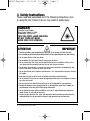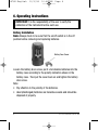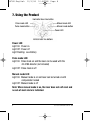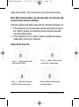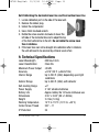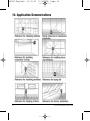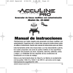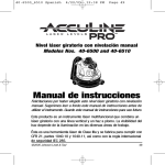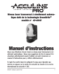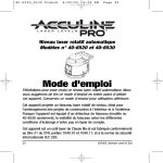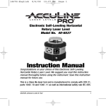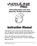
1
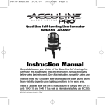
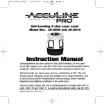
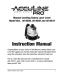
1676H-English
10/3/08
10:46 AM
Page 1
®
Self-Leveling Cross Line Laser Level
with 3 Vertical Lines
Model No. 40-6602
Instruction Manual
Congratulations on your choice of this Self-Leveling Cross Line Laser
Level with 3 vertical lines. We suggest you read this instruction
manual thoroughly before using the instrument. Save this instruction
manual for future use.
This tool emits one laser cross and two vertical line at 90º. The tool
features quick damping, visual and audible out of range indication, and
a pendulum-locking design. Beam visibility depends upon lighting
conditions in the work area.
This is a Class IIIa laser tool and is manufactured to comply with CFR 21,
parts 1040 .10 and 1040 .11 as well as international safety rule IEC 285.
©2008 Johnson Level & Tool
1
1676H-English
10/3/08
10:46 AM
Page 2
Table of Contents
1. Kit Contents
2. Features and Functions
3. Safety Instructions
4. Location/Content
of Warning Labels
5. Location of Parts/Components
6. Operating Instructions
7. Using the Product
8.
9.
10.
11.
12.
13.
14.
Self-Check and Calibration
Technical Specifications
Application Demonstrations
Care and Handling
Product Warranty
Product Registration
Accessories
1. Kit Contents
Description
Self-Leveling Cross Line Laser Level
with 3 Vertical Lines
Tripod/Wall Mount Bracket
“AA” Alkaline Batteries
Tinted Goggles
Magnetic Target
Instruction Manual with Warranty Card
Soft Sided Carrying Case
Qty.
1
1
3
1
1
1
1
2. Features and Functions
• Indoor and outdoor use (for outdoor use must use 40-6780 detector, not
included)
• Simultaneously projects three vertical lines and one horizontal
line to form a cross line in front of the laser.
• Locking mechanism protects inner pendulum during transportation.
• Self-Leveling with visual and audible alarms when beyond
leveling range.
• Emits continuously both a solid and pulse beam (pulse beam
for use with detector).
• Manual mode allows unit to tilt to extreme angles.
2
©2008 Johnson Level & Tool
1676H-English
10/3/08
10:46 AM
Page 3
3. Safety Instructions
Please read and understand all of the following instructions, prior
to using this tool. Failure to do so, may result in bodily injury.
DANGER!
Class IIIa Laser Product
Max. Power Output: ≤ 5mW
Wavelength: 625-645nm
THIS TOOL EMITS LASER RADIATION.
DO NOT STARE INTO BEAM.
AVOID DIRECT EYE EXPOSURE.
ATTENTION
IMPORTANT
• Read all instructions prior to operating this laser tool. Do not remove any labels from tool.
• Use of controls or performance of procedures other than those specified herein may void warranty.
• Do not stare directly at the laser beam.
• Do not project the laser beam directly into the eyes of others.
• Do not set up laser tool at eye level or operate the tool near a reflective surface as the
laser beam could be projected into your eyes or into the eyes of others.
• Do not place the laser tool in a manner that may cause someone to unintentionally look
into the laser beam. Serious eye injury may result.
• Do not operate the tool in explosive environments, i.e. in the presence of gases or flammable liquids.
• Keep the laser tool out of the reach of children and other untrained persons.
• Do not attempt to view the laser beam through optical tools such as telescopes as serious
eye injury may result.
• Always turn the laser tool off when not in use or left unattended for a period of time.
• Remove the batteries when storing the tool for an extended time (more than 3 months) to
avoid damage to the tool should the batteries deteriorate.
• Do not attempt to repair or disassemble the laser tool. If unqualified persons attempt to
repair this tool, it may void the warranty.
• Use only original AccuLine Pro® parts and accessories purchased from your AccuLine Pro
authorized dealer. Use of non-AccuLine Pro parts and accessories will void warranty.
©2008 Johnson Level & Tool
3
1676H-English
10/3/08
10:46 AM
Page 4
4. Location/Content of Warning Labels
4
©2008 Johnson Level & Tool
1676H-English
10/3/08
10:46 AM
Page 5
5. Location of Part/Components
Keypad
Battery Door
Screw
Battery Door
Laser
Emitting
Window
Laser
Emitting
Window
6V Plug
(adapter
not included)
Screw Hole
Bench Mark Locator Insert
5/8” thread
Graduated Circle
©2008 Johnson Level & Tool
5
1676H-English
10/3/08
10:46 AM
Page 6
6. Operating Instructions
IMPORTANT: It is the responsibility of the user to verify the
calibration of the instrument before each use.
Battery Installation
Note: Always check to be sure that the on/off switch is in the off
position before removing and replacing batteries.
Battery Door Screw
Loosen the battery door screw, put 3 x AA alkaline batteries into the
battery case according to the polarity indication shown in the
battery case. Then put the cover back on and tighten the battery
door screw.
Note:
• Pay attention to the polarity of the batteries.
• Used (discharged) batteries are hazardous waste and should be
disposed of properly.
6
©2008 Johnson Level & Tool
1676H-English
10/3/08
10:46 AM
Page 7
Wall Mount/Tripod Adapter
1. Put the instrument into the wall mount. The unit can rotate 360º.
2. The wall mount can be mounted on a wall.
3. The benchmark locator insert can be used to find a point on
the ground.
4. The wall mount can be attached to a tripod.
Hanging on Wall
Rotating 360º
Connected to a tripod
Put the bench
mark locator
into 5/8” screw
thread hole.
Benchmark locator insert usage
©2008 Johnson Level & Tool
Put the center
of the benchmark locator
on the mark
on the floor,
then put in the
instrument.
7
1676H-English
10/3/08
10:46 AM
Page 8
7. Using the Product
Horizontal laser line button
Manual mode LED
Pulse mode LED
Manual mode button
Pulse mode button
Power LED
Vertical laser line buttons
Power LED:
Light On: Power on
Light Off: Power off
Light Flashing: Low Battery
Pulse mode LED:
Light On: Pulse mode on and the laser can be used with the
40-6780 detector (not included)
Light Off: Pulse mode is off
Manual mode LED:
Light On: Manual mode is on and laser can be turned on with
compensator locked
Light Off: Manual mode is off
Note: When manual mode is on, the laser does not self-level and
no out-of-level alarm is indicated.
8
©2008 Johnson Level & Tool
1676H-English
10/3/08
10:46 AM
Page 9
Compensator Transportation Lock
Hold the upper housing of the instrument, and turn the base in the
direction of the arrow.
To lock the compensator transportation
lock, turn the base to the off position.
To unlock the compensator transportation
lock, turn the base to the on position.
When the instrument is in the “Unlock” position, the power LED will light.
When the instrument is in the “Lock” position, the power LED will be off.
Pulse Mode:
Unlock the transportation lock and press the horizontal and/or vertical
laser line buttons. Then press the pulse mode button to turn on the
pulse mode, the pulse mode LED will turn on and the laser beam line
will dim. The laser line can now be located by a detector (not included).
Press the pulse mode button again to switch off the pulse mode, the
pulse mode LED will turn off. The laser line now can not be located
with a detector.
Manual Mode:
Press the manual mode button with the transportation lock knob in
the “Locked” position. The power LED will light and the manual
©2008 Johnson Level & Tool
9
1676H-English
10/3/08
10:46 AM
Page 10
mode LED will flash. The instrument is now in the manual mode.
Note: When manual mode is on, the laser does not self-level and
no out-of-level alarm is indicated.
Press the manual mode button again and the instrument will power off.
1. If the instrument is in manual mode and the instrument is turned to
the “Unlock” position, the instrument will exit manual mode and
enter self-leveling mode.
2. If the instrument is in the “Unlock” position, pressing the manual
mode button will not get a response.
Output of the laser line
Press
button to form the horizontal laser line above
Press
button to form the two
vertical laser lines shown above
10
Press
button to form the vertical laser line as shown above
Press all buttons to form the laser
lines shown above
©2008 Johnson Level & Tool
1676H-English
10/3/08
10:46 AM
Page 11
8. Self-Check and Calibration
IMPORTANT: It is the responsibility of the user to verify the
calibration of the instrument before each use.
Horizontal Line for Level
1. Set the wall mount/tripod adapter on a tripod or flat surface approximately 10 ft. away from a reference wall.
2. Unlock the transportation lock on the unit.
3. Set the laser inside the wall mount/tripod adapter.
4. Press the horizontal laser line button (H) and the Vertical Laser Line
button (V1).
5. Point the cross line at the reference wall (It is important to see the
laser line very clearly. This test should be performed indoors and
in low light conditions).
6. Mark the intersection of the cross line as point A.
7. Rotate the laser unit counter clockwise until the laser cross line is 8 feet
away from point A (to the left of point A). Mark the laser line at point A
as point B.
8. Rotate the laser unit clockwise until the cross line is 8 feet to the right
of point A.
9. Mark the laser line at Point A as point C.
10.If the distance between point B and point C is greater then 1/16” the
unit needs to be recalibrated. (See calibration information)
©2008 Johnson Level & Tool
11
1676H-English
10/3/08
10:46 AM
Page 12
3 Vertical Lines for Plumb
1. Use a plumb line or known vertical reference point.
2. Turn the laser unit on following the instructions above.
3. Rotate the laser unit so the vertical laser line intersects the plumb line.
4. Check all three vertical lines.
5. If the vertical laser line is not parallel with the plumb line (i.e. intersects
at the top and bottom), the unit needs to be recalibrated. (See
calibration information).
Self-Calibration Adjustment
Self-Calibrating the side vertical laser lines (not the front
vertical laser line) for plumb
1. There are two self calibration ports inside the battery compartment.
2. Remove the rubber plugs.
3. Unlock the compensator.
4. Use a 2mm hex head wrench.
5. Turn the calibration screw counter clockwise to
move the top of the side vertical lines back towards
the battery compartment. Move one screw at time.
Do not rotate the screw more then 4 rotations. If the vertical line is
still not plumb after moving one screw 4 rotations, the second screw
can be rotated in the same direction. Do not rotate the second screw
more then 4 rotations.
6. If the vertical lines can not be brought into plumb after 4 rotations of
each screw, the unit will need to be serviced by Johnson Level & Tool.
12
©2008 Johnson Level & Tool
1676H-English
10/3/08
10:46 AM
Page 13
Self-Calibrating the horizontal laser line and front vertical laser line
1. Locate calibration port on the side of the laser unit.
2. Remove the rubber plug.
3. Unlock the compensator.
4. Use a 2mm hex head wrench.
5. Rotate the screw counter clockwise to lower the
left side of the horizontal line and to adjust the top
of the front vertical line to the left. Do not rotate the screw more
then 4 rotations.
6. If the laser lines can not be brought into calibration after 4 rotations
the unit will need to be serviced by Johnson Level & Tool.
9. Technical Specifications
Laser Wavelength
Laser Classification
Maximum Power Output
Accuracy
Interior Range
Exterior Range
Self-leveling Range
Power Supply
Battery Life
Dimensions
Weight
Working Temperature
Center Screw Thread
IP Protection
©2008 Johnson Level & Tool
635nm±10nm
Class IIIa
≤5mW
±3/16"/50 ft. (±3mm/10m)
Up to 200 ft. (60m) depending upon light
conditions
Up to 300 ft. (90m) with detector
±3°
3 “AA” alkaline batteries
Approx. battery life 10 hours continuous use
3.55" x 5.83" (90 x 148mm)
2.2 lbs (1.0 Kg)
14°F to 113°F (-10°C to +45°C)
5/8" – 11
54
13
1676H-English
10/3/08
10:46 AM
Page 14
10. Application Demonstrations
14
©2008 Johnson Level & Tool
1676H-English
10/3/08
10:46 AM
Page 15
11. Care and Handling
Care must be taken to maintain the accuracy of the instrument.
• After
each use, the instrument should be wiped clean and kept in
its carrying case.
• Remove dust from the lenses with a soft brush or a nonabrasive
wipe. Never touch the lenses with your fingers.
• Store the instrument in a dust-free area with low humidity.
• A bag of silica gel dryer is included with each instrument.
12. Product Warranty
Johnson Level & Tool offers a one year limited warranty on each its
products. You can obtain a copy of the limited warranty for a
Johnson Level & Tool product by contacting Johnson Level & Tool's
Customer Service Department as provided below or by visiting us
online at www.johnsonlevel.com. The limited warranty for each
product contains various limitations and exclusions.
Do not return this product to the store/retailer or place of purchase.
Required repair/calibration must be done by an authorized
AccuLine Pro® service center or Johnson Level & Tool's limited
warranty, if applicable, will be void and there will be NO WARRANTY.
Contact our Customer Service Department to obtain a Return Material
Authorization (RMA) number for return to an authorized service center.
Proof of purchase is required.
NOTE: The user is responsible for the proper use and care of the
product.
©2008 Johnson Level & Tool
15
1676H-English
10/3/08
10:46 AM
Page 16
It is the responsibility of the user to verify the calibration of the
instrument before each use.
For further assistance, or if you experience problems with this product
that are not addressed in this instruction manual, please contact our
Customer Service Department.
In the U.S., contact Johnson Level & Tool’s Customer Service
Department at 800-563-8553.
In Canada, contact Johnson Level & Tool’s Customer Service
Department at 800-346-6682.
13. Product Registration
Enclosed with this instruction manual you will find a warranty card to be
completed for product warranty registration. Product warranty registration
can also be completed online at our web site www.johnsonlevel.com.
You will need to locate the serial number for your product that is located
on the bottom of the unit. PLEASE NOTE THAT IN ADDITION TO ANY
OTHER LIMITATIONS OR CONDITIONS OF JOHNSON LEVEL &
TOOL'S LIMITED WARRANTY, JOHNSON LEVEL & TOOL MUST
HAVE RECEIVED YOUR PROPERLY COMPLETED WARRANTY CARD
WITHIN 30 DAYS OF YOUR PURCHASE OF THE PRODUCT OR ANY
LIMITED WARRANTY THAT MAY APPLY SHALL NOT APPLY AND
THERE SHALL BE NO WARRANTY.
16
©2008 Johnson Level & Tool
1676H-English
10/3/08
10:46 AM
Page 17
14. Accessories
AccuLine Pro® accessories are available for purchase through
authorized AccuLine Pro dealers. Use of non-AccuLine Pro accessories
will void any applicable limited warranty and there will be NO WARRANTY.
If you need any assistance in locating any accessories, please contact
our Customer Service Department.
In the U.S., contact Johnson Level & Tool’s Customer Service
Department at 800-563-8553.
In Canada, contact Johnson Level & Tool’s Customer Service
Department at 800-346-6682.
©2008 Johnson Level & Tool
17
1676H-English
18
10/3/08
10:46 AM
Page 18
©2008 Johnson Level & Tool