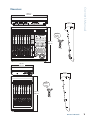
1
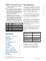
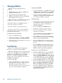
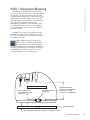
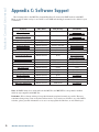
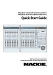
MCU Pro MCU XT Pro Universal Control Surface Universal Control Surface Extender OWNER’S MANUAL EXTERNAL POWER MIDI UNIVERSAL CONTROL SURFACE EXTENDER IN OUT MAIN POWER PORT 2 PORT1 (INTERNAL) = MCU 7.5V 3.0A-4.0A PORT 3 IN OUT PORT 4 IN OUT EXTERNAL CONTROL USER SWITCH IN 1 OUT UNIVERSAL CONTROL SURFACE 2 7.5V MINUTES HOURS POWER EXTERNAL POWER SECONDS 3.0A-4.0A FRAMES SMPTE RUDE SOLO BEATS ASSIGNMENT 1 2 3 4 5 6 7 8 1 2 3 4 5 6 7 8 BARS BEATS SUB DIVISION TICKS VPOT ASSIGN DISPLAY UNIVERSAL CONTROL SURFACE TRACK REC REC SIGNAL SIGNAL REC REC SIGNAL REC SIGNAL SIGNAL REC REC REC REC REC REC REC REC REC REC REC SIGNAL SIGNAL SIGNAL SIGNAL SIGNAL SIGNAL SIGNAL SIGNAL SIGNAL SIGNAL SIGNAL SOLO SOLO SOLO SOLO SOLO SOLO SOLO SOLO MUTE MUTE MUTE MUTE MUTE MUTE MUTE MUTE SEND PAN/ SURROUND PLUG-IN EQ INSTRUMENT NAME VALUE SMPTE BEATS FUNCTION SELECT F1 F2 F3 F4 F5 F6 F7 F8 BUSSES OUTPUTS FADER BANKS GLOBAL VIEW BANK MIDI TRACKS INPUTS AUDIO TRACKS AUDIO INSTRUMENT AUX USER CHANNEL SELECT SELECT SELECT SELECT SELECT SELECT SELECT MODIFIERS SELECT FLIP + dB dB dB dB dB dB dB + + + + + + SHIFT + + dB 10 10 5 5 5 5 5 5 5 5 5 5 U U U U U U U U U U U U U U U U U 5 5 5 5 5 5 5 5 5 5 5 5 5 5 5 5 5 0 0 0 + 10 0 + 10 0 + 10 0 + 10 0 0 0 0 0 0 0 10 dB 5 10 10 dB 5 + 10 dB 5 10 10 dB 5 + 10 dB 5 10 10 dB 5 + 10 dB 5 10 0 0 10 10 10 10 10 10 10 10 10 10 10 10 10 10 10 10 20 20 20 20 20 20 20 20 20 20 20 20 20 20 20 20 20 30 30 30 30 30 30 30 30 30 30 30 30 30 30 30 30 30 40 40 40 40 40 40 40 40 40 40 40 40 40 40 40 40 40 50 50 60 60 60 50 – 60 50 – 60 50 – 60 50 – 60 50 – 60 50 – 60 50 50 – 60 – 60 50 – 60 50 – 60 50 – 60 50 – 60 50 – 60 50 – OPTION READ/OFF WRITE TRIM SAVE UNDO /ALT TOUCH LATCH GROUP CANCEL ENTER NUDGE CYCLE DROP REPLACE CLICK SOLO CONTROL MARKER 0 10 50 – dB UTILITIES GLOBAL VIEW MASTER dB AUTOMATION 60 – REWIND FAST FWD STOP PLAY RECORD SCRUB ZOOM Mackie Control Universal Important Safety Instructions 14. Refer all servicing to qualified service personnel. Servicing is required when the apparatus has been damaged in any way, such as power-supply cord or plug is damaged, liquid has been spilled or objects have fallen into the apparatus, the apparatus has been exposed to rain or moisture, does not operate normally, or has been dropped. 1. Read these instructions. 2. Keep these instructions. 3. Heed all warnings. 4. Follow all instructions. 5. Do not use this apparatus near water. 6. Clean only with a dry cloth. 7. Do not block any ventilation openings. Install in accordance with the manufacturer’s instructions. 8. Do not install near any heat sources such as radiators, heat registers, stoves, or other apparatus (including amplifiers) that produce heat. 9. Do not defeat the safety purpose of the polarized or groundingtype plug. A polarized plug has two blades with one wider than the other. A grounding-type plug has two blades and a third grounding prong. The wide blade or the third prong are provided for your safety. If the provided plug does not fit into your outlet, consult an electrician for replacement of the obsolete outlet. 10. Protect the power cord from being walked on or pinched particularly at plugs, convenience receptacles, and the point where they exit from the apparatus. 11. Only use attachments/accessories specified by the manufacturer. 12. Use only with a cart, stand, tripod, bracket, or table specified by the manufacturer, or sold with the apparatus. When a cart is used, use caution when moving the cart/apparatus combination to avoid injury from tip-over. PORTABLE CART WARNING 13. Unplug this apparatus during lightning storms or when unused for long periods of time. 15. This apparatus shall not be exposed to dripping or splashing, and no object filled with liquids, such as vases or beer glasses, shall be placed on the apparatus. 16. Do not overload wall outlets and extension cords as this can result in a risk of fire or electric shock. 17. The MAINS plug or an appliance coupler is used as the disconnect device, so the disconnect device shall remain readily operable. 18.NOTE: This equipment has been tested and found to comply with the limits for a Class B digital device, pursuant to part 15 of the FCC Rules. These limits are designed to provide reasonable protection against harmful interference in a residential installation. This equipment generates, uses, and can radiate radio frequency energy and, if not installed and used in accordance with the instructions, may cause harmful interference to radio communications. However, there is no guarantee that interference will not occur in a particular installation. If this equipment does cause harmful interference to radio or television reception, which can be determined by turning the equipment off and on, the user is encouraged to try to correct the interference by one or more of the following measures: • Reorient or relocate the receiving antenna. • Increase the separation between the equipment and the receiver. • Connect the equipment into an outlet on a circuit different from that to which the receiver is connected. CAUTION AVIS RISK OF ELECTRIC SHOCK. DO NOT OPEN RISQUE DE CHOC ELECTRIQUE. NE PAS OUVRIR CAUTION: TO REDUCE THE RISK OF ELECTRIC SHOCK DO NOT REMOVE COVER (OR BACK) NO USER-SERVICEABLE PARTS INSIDE. REFER SERVICING TO QUALIFIED PERSONNEL ATTENTION: POUR EVITER LES RISQUES DE CHOC ELECTRIQUE, NE PAS ENLEVER LE COUVERCLE. AUCUN ENTRETIEN DE PIECES INTERIEURES PAR L'USAGER. CONFIER L'ENTRETIEN AU PERSONNEL QUALIFIE. AVIS: POUR EVITER LES RISQUES D'INCENDIE OU D'ELECTROCUTION, N'EXPOSEZ PAS CET ARTICLE A LA PLUIE OU A L'HUMIDITE The lightning flash with arrowhead symbol within an equilateral triangle is intended to alert the user to the presence of uninsulated "dangerous voltage" within the product's enclosure, that may be of sufficient magnitude to constitute a risk of electric shock to persons. Le symbole éclair avec point de flèche à l'intérieur d'un triangle équilatéral est utilisé pour alerter l'utilisateur de la présence à l'intérieur du coffret de "voltage dangereux" non isolé d'ampleur suffisante pour constituer un risque d'éléctrocution. The exclamation point within an equilateral triangle is intended to alert the user of the presence of important operating and maintenance (servicing) instructions in the literature accompanying the appliance. Le point d'exclamation à l'intérieur d'un triangle équilatéral est employé pour alerter les utilisateurs de la présence d'instructions importantes pour le fonctionnement et l'entretien (service) dans le livret d'instruction accompagnant l'appareil. • Consult the dealer or an experienced radio/TV technician for help. CAUTION: Changes or modifications to this device not expressly approved by LOUD Technologies Inc. could void the user's authority to operate the equipment under FCC rules. 19. This apparatus does not exceed the Class A/Class B (whichever is applicable) limits for radio noise emissions from digital apparatus as set out in the radio interference regulations of the Canadian Department of Communications. WARNING — To reduce the risk of fire or electric shock, do not expose this apparatus to rain or moisture. Correct Disposal of this product: This symbol indicates that this product should not be disposed of with your household waste, according to the WEEE Directive (2002/96/EC) and your national law. This product should be handed over to an authorized collection site for recycling waste electrical and electronic equipment (EEE). Improper handling of this type of waste could have a possible negative impact on the environment and human health due to potentially hazardous substances that are generally associated with EEE. At the same time, your cooperation in the correct disposal of this product will contribute to the effective usage of natural resources. For more information about where you can drop off your waste equipment for recycling, please contact your local city office, waste authority, or your household waste disposal service. 2 Mackie Control Universal 20. Exposure to extremely high noise levels may cause permanent hearing loss. Individuals vary considerably in susceptibility to noise-induced hearing loss, but nearly everyone will lose some hearing if exposed to sufficiently intense noise for a period of time. The U.S. Government’s Occupational Safety and Health Administration (OSHA) has specified the permissible noise level exposures shown in the following chart. According to OSHA, any exposure in excess of these permissible limits could result in some hearing loss. To ensure against potentially dangerous exposure to high sound pressure levels, it is recommended that all persons exposed to equipment capable of producing high sound pressure levels use hearing protectors while the equipment is in operation. Ear plugs or protectors in the ear canals or over the ears must be worn when operating the equipment in order to prevent permanent hearing loss if exposure is in excess of the limits set forth here: Duration, per Sound Level dBA, Typical Example day in hours Slow Response 8 6 4 3 2 1.5 1 0.5 0.25 or less 90 92 95 97 100 102 105 110 115 Duo in small club Subway Train Very loud classical music B-en and M-att screaming at T-roy about deadlines Loudest parts at a rock concert Contents IMPORTANT SAFETY INSTRUCTIONS INTRODUCTION SOFTWARE USER’S GUIDE CHANGING MODES INSTALLATION VESA / OMNIMOUNT MOUNTING HOOKUP DIAGRAMS FRONT PANEL CHANNEL STRIP MASTER SECTION REAR PANEL APPENDIX A: KEY COMMANDS APPENDIX B: FADER ALIGNMENT APPENDIX C: SOFTWARE SUPPORT APPENDIX C: SERVICE INFORMATION APPENDIX D: TECHNICAL INFORMATION DIMENSIONS LIMITED WARRANTY 2 3 3 4 4 5 6 7 7 8 9 10 11 12 13 14 15 16 Introduction Thank you for choosing Mackie for your Digital Audio Workstation (DAW) control solution. MCU Pro and MCU XT Pro provide the familiar feel of analog-style mixing to the DAW environment. But they also deliver the most complete feature set and software compatibility of any control surface available today, including USB connectivity. The labels for the buttons and controls are specific to Apple Logic Pro. Custom lexan overlays are available for other supported DAWs. Some of these are included with the MCU Pro and others may be ordered from our parts department. Owner’s Manual ATTENTION — Le présent appareil numérique n’émet pas de bruits radioélectriques dépassant las limites applicables aux appareils numériques de class A/de class B (selon le cas) prescrites dans le réglement sur le brouillage radioélectrique édicté par les ministere des communications du Canada. These overlays fit over the right-hand side of the control surface and correctly label the buttons for the functionality supported by the DAW being utilized. Visit www.mackie.com/products/mcupro/ mcupro_software to see a list of all currently supported DAWs, and to order an overlay for your particular DAW application. The MCU Pro includes a license for Tracktion, our easy-to-use Music Production Software for PC or Mac. It is the perfect companion software for the MCU Pro. Follow the instructions on the included license card to download and authorize Tracktion. Overlays Included Overlays Available Steinberg Cubase / Nuendo Adobe Audition MOTU Digital Performer Ableton Live Avid Pro Tools Propellerhead Reason Cakewalk Sonar RML Labs SAW Studio Mackie Tracktion SSL Soundscape Sony Vegas Software User’s Guide Visit www.mackie.com/products/mcupro/ to obtain the latest manuals and information for all the currently supported DAW applications. Part No. SW0454 Rev. C 10/10 ©2007-2010 LOUD Technologies Inc. All Rights Reserved. Owner’s Manual 3 Mackie Control Universal Changing Modes MCU Pro has three different modes of operation: Connecting with MIDI • Connect the MCU Pro to the MIDI interface via two MIDI cables (IN and OUT). Use the MIDI 2 (MAIN) MIDI connections on the MCU Pro. • Connect the third-party MIDI interface to the computer as described by the manufacturer (see “Hookup 2: MIDI” on page 6). 1. Mackie Control (use with most DAWs. See Appendix C on page 12). 2. Logic Control (use with Apple Logic). 3. HUI (use with Avid Pro Tools, including HD, LE, and M Powered versions). When first turning on the MCU Pro, the display prompts you to select a mode of operation: For both methods: • Connect one end of the external power supply to the MCU Pro, and the other end to an AC power source between 100 VAC and 240 VAC (50–60 Hz). • Turn on the MCU Pro POWER switch. • Launch the software program of choice. • Select your software’s console or surface manager set up window. To change the mode of operation: • Select the Mackie Control in the MIDI device setup section of your DAW application. 1. Turn off the Mackie Control. • Once the Mackie Control is selected within your software’s setup preferences, the unit(s) will be recognized automatically. • MCU Pro / MCU XT Pro units may function as a single large console – a “Control Surface Group.” • Go to the MCU Pro software section on our website (www.mackie.com/products/mcupro/ mcupro_software) for details on using the MCU Pro with your particular application. • Press Ch. 1 V-Pot to select Mackie Control. • Press Ch. 4 V-Pot to select HUI. • Press Ch. 8 V-Pot to select Logic Control. Once the selection has been made, MCU Pro will automatically boot into the selected mode each time it is powered up. 2. Hold down both the Ch. 1 and Ch. 2 SELECT buttons while turning on the Mackie Control. 3. The display once again prompts you to select a mode of operation. Installation There are two methods for connecting the MCU Pro to a computer: USB and MIDI. Note: The USB method is the preferred method because all of the MIDI ports on the MCU Pro are available. If using MIDI cables to connect the MCU Pro to a computer via third-party MIDI interface, the other two MIDI ports (3 and 4) on the MCU Pro are inactive. Connecting with USB • 4 Connect the MCU Pro to a computer with a USB cable (see “Hookup 1: USB” on page 6). The USB connection works with both Macintosh and PC platforms and is “plug and play” (no driver installation required!). Mackie Control Universal To connect one or more MCU XT Pros: 1. If using the USB method to connect the MCU Pro to a computer, then the MCU Pro has three sets of MIDI IN/OUT connectors for connecting additional MCU XT Pro units. Always connect MIDI OUT from one unit to MIDI IN on the next unit (and MIDI IN to MIDI OUT). 2. If using the MIDI method to connect the MCU Pro to a computer, then connect the MCU XT Pro to the external USB MIDI interface [the MIDI 3 and MIDI 4 connectors on the MCU Pro are not functional using this method]. Connect the MIDI OUT from the MCU XT Pro to the MIDI IN on the MIDI interface (and MIDI IN to MIDI OUT). Owner’s Manual VESA / Omnimount Mounting The MCU Pro and MCU XT Pro have holes in the bottom panel for mounting to a standard VESA wall mount or floating arm mount, using 75 mm or 100 mm mounting patterns. These holes accept M4 (4 mm) screws. The length of the screw will vary depending on the thickness of the mounting plate. The screw length is calculated by determining the thickness of the mounting plate and adding 0.25 inches to that for the threads to engage the pemnut in the bottom of the MCU Pro (see figure below). The MCU Pro weighs 16.8 lb (7.6 kg) and the MCU XT Pro weighs 11.0 lb (5.0 kg), so be sure to select a mounting arm or plate that can support the weight of the unit. Many VESA mounts are designed for video monitors, and the mounting plate is perpindicular to the desktop surface. Since it is unlikely that you will want the MCU Pro mounted perpindicular to the desktop, make sure the VESA mount is flexible enough so it may be properly adjusted for your working space. MCU Pro or MCU XT Pro 0.153 in/3.88 mm Thread Engagement (8 places) M4 (4 mm) Pemnut (8 places) 0.868 in/22.06 mm Clearance for MCU Pro 0.469 in/11.91 mm Clearance for MCU XT Pro Mounting Plate Mounting Plate Thickness + 0.25 in = length of screw Owner’s Manual 5 Mackie Control Universal Hookup Diagrams MCU XT Pro MCU Pro MAIN PORT 2 PORT1 IN PORT 3 OUT IN PORT 4 OUT IN EXTERNAL CONTROL USER SWITCH 1 OUT UNIVERSAL CONTROL SURFACE 2 MCU XT Pro EXTERNAL POWER MIDI POWER UNIVERSAL CONTROL SURFACE EXTENDER IN OUT EXTERNAL POWER 7.5V POWER MCU XT Pro EXTERNAL POWER MIDI UNIVERSAL CONTROL SURFACE EXTENDER 7.5V 3.0A-4.0A IN OUT POWER MIDI IN MIDI OUT IN MIDI IN MIDI OUT MIDI IN This setup provides the ultimate in DAW control: 32 faders with 32 V-Pots. Digital Audio Workstation USB Connection You may purchase short MIDI cables to keep the cabling neat and tidy when connecting the MCU XT Pros to the MCU Pro. Hookup 1: USB MCU XT Pro MCU Pro MAIN PORT 2 PORT1 (INTERNAL) = MCU IN PORT 3 OUT IN PORT 4 OUT IN EXTERNAL CONTROL USER SWITCH 1 OUT UNIVERSAL CONTROL SURFACE 2 MCU XT Pro EXTERNAL POWER MIDI POWER UNIVERSAL CONTROL SURFACE EXTENDER IN EXTERNAL POWER 7.5V MIDI IN OUT POWER EXTERNAL POWER MIDI UNIVERSAL CONTROL SURFACE EXTENDER 7.5V 3.0A-4.0A IN OUT POWER 7.5V 3.0A-4.0A 3.0A-4.0A MIDI IN MIDI OUT MIDI OUT MIDI IN MIDI OUT Digital Audio Workstation Connection (typically USB) Third-party Multiport MIDI Interface Hookup 2: MIDI MCU XT Pro MCU Pro MIDI Drum Controller MIDI Synth Keyboard MAIN PORT 2 PORT1 IN PORT 3 OUT IN PORT 4 OUT IN EXTERNAL CONTROL USER SWITCH OUT 1 UNIVERSAL CONTROL SURFACE 2 POWER UNIVERSAL CONTROL SURFACE EXTENDER EXTERNAL POWER 7.5V 3.0A-4.0A MIDI IN Digital Audio Workstation USB Connection Hookup 3: With Multiple MIDI Devices 6 Mackie Control Universal EXTERNAL POWER MIDI UNIVERSAL CONTROL SURFACE EXTENDER 7.5V 3.0A-4.0A OUT POWER 7.5V 3.0A-4.0A 3.0A-4.0A MIDI OUT MIDI IN MIDI OUT MIDI IN MIDI OUT MIDI OUT 2. SELECT Although the functions of the knobs and buttons on the MCU Pro will vary depending on which software application is being utilized, this section provides an overview of the control surface and a general explanation of what it can do. Note that not all controls are implemented by each software platform. Check out the FAQ section on the Mackie website for more information: www.mackie.com/products/mcupro/mcupro_faq This button selects the corresponding channel for channel-based editing or assignment commands. Channel Strip Pushing a SOLO button isolates that channel’s output signal to the mix bus in the DAW application. 3. MUTE The MUTE button turns off the corresponding channel’s output signal. 4. SOLO Owner’s Manual Front Panel Note: When one or more SOLO buttons are active, the RUDE SOLO LED next to the Time Display lights to signal that one or more channels are soloed. 1. TOUCH-SENSITIVE FADERS These 100mm, touch-sensitive, motorized faders are used to control the channel’s levels, aux returns, MIDI tracks, and master fader levels. The eight faders move relative to the activity of the currently selected bank of on-screen faders. 5. SIGNAL This LED illuminates when a signal is present in the corresponding channel. 6. REC This button arms or disables the corresponding track for recording. MINUTES HOURS SECONDS FRAMES SMPTE RUDE SOLO BEATS ASSIGNMENT BARS 7. V-POT 1 2 3 4 5 6 BEATS SUB DIVISION TICKS The V-Pots serve a dual function on the Mackie Control, acting as a push-button and a rotary control. When a V-Pot is pressed, it may be used to change modes of operation or to change what appears in the display above the channel strips. 7 8 VPOT ASSIGN DISPLAY UNIVERSAL CONTROL SURFACE REC REC REC REC REC REC REC REC SIGNAL SIGNAL SIGNAL SIGNAL SIGNAL SIGNAL SIGNAL SIGNAL TRACK SEND PAN/ SURROUND PLUG-IN NAME VALUE SMPTE BEATS FUNCTION SELECT Depending on its assigned function, a V-Pot may be used to adjust a channel’s pan, send level, or plug-in parameters when rotated. EQ INSTRUMENT F1 F2 F3 F4 F5 F6 F7 F8 BUSSES OUTPUTS USER FADER BANKS GLOBAL VIEW BANK MIDI TRACKS INPUTS AUDIO TRACKS AUDIO INSTRUMENT AUX CHANNEL MODIFIERS FLIP SHIFT MASTER dB + 10 dB + dB + 10 dB + 10 dB + 10 dB + 10 dB + 10 + dB dB 10 10 5 5 5 5 5 5 5 5 5 U U U U U U U U U 5 5 5 5 5 5 5 5 5 10 10 0 0 10 0 10 0 10 0 10 0 10 0 10 0 10 20 20 20 20 20 20 20 30 30 30 30 30 30 30 40 40 40 40 40 40 40 50 – 10 60 50 – 60 50 – 60 50 – 60 50 – 60 50 – 60 50 – 60 – AUTOMATION UTILITIES GLOBAL VIEW READ/OFF WRITE TRIM SAVE UNDO /ALT TOUCH LATCH GROUP CANCEL ENTER NUDGE CYCLE DROP REPLACE CLICK SOLO OPTION CONTROL MARKER 8. SCRIBBLE STRIP This backlit LCD above the channel strips displays track names, plug-in parameters, and other information depending on the channel strips’ current mode of operation. 20 20 30 30 40 40 50 50 60 60 REWIND FAST FWD STOP PLAY RECORD SCRUB ZOOM Owner’s Manual 7 Mackie Control Universal Master Section 9. V-POT ASSIGN 16. MODE LED DISPLAY These six buttons are used to assign different functions to the V-Pots. These usually include Pan, Aux Send, EQ, Plug-In Effects, and Track level. This indicates the current mode of operation for the channel strips. 10. BANKS and CHANNELS Pressing the left or right BANK button jumps over to the next adjacent eight channels on either the left or right side of the current location. MINUTES HOURS SECONDS FRAMES SMPTE RUDE SOLO BEATS ASSIGNMENT If one or more MCU XT Pros are present, the BANK buttons may jump over by 8 times the 1 2 3 4 For example, 5 6 7 number of devices present. if two MCU XT Pros are present in addition to the MCU Pro, the BANK buttons may jump 8 x 3 or 24 channels at a time. 8 BARS BEATS SUB DIVISION TICKS VPOT ASSIGN DISPLAY UNIVERSAL CONTROL SURFACE REC REC REC REC REC REC REC REC SIGNAL SIGNAL SIGNAL SIGNAL SIGNAL SIGNAL SIGNAL SIGNAL Pressing the left or right CHANNEL button jumps over to the next adjacent channel on either the left or right side of the current location. TRACK SEND PAN/ SURROUND PLUG-IN EQ INSTRUMENT NAME VALUE SMPTE BEATS FUNCTION SELECT F1 F2 F3 F4 F5 F6 F7 F8 BUSSES OUTPUTS USER FADER BANKS GLOBAL VIEW BANK MIDI TRACKS 11. FUNCTION SELECT dB 10 dB + 10 dB + 10 dB + 10 dB + 10 dB + 10 dB + 10 dB dB 10 10 5 5 5 5 5 5 U U U U U U U U U 5 5 5 5 5 5 5 5 5 0 0 0 0 0 10 10 10 10 10 10 10 10 20 20 20 20 20 20 20 20 20 30 30 30 30 30 30 30 30 30 40 40 40 40 40 40 40 40 40 50 50 60 60 50 60 50 – 60 50 – 60 AUX 50 – 60 50 – 60 50 – 60 50 – 60 13. JOG / SHUTTLE WHEEL Use the button to toggle between Jog and Shuttle functions for the large wheel. Use the wheel for editing audio in the DAW application. 14. ZOOM AND NAVIGATION BUTTONS These four arrow buttons and the zoom button are used to navigate around the graphic editor in the DAW application. 15. TIME DISPLAY This display shows the time location of the project in either SMPTE or BBT (bar.beat.ticks) format. Mackie Control Universal AUTOMATION UTILITIES READ/OFF WRITE TRIM SAVE UNDO /ALT TOUCH LATCH GROUP CANCEL ENTER NUDGE CYCLE DROP REPLACE CLICK SOLO OPTION CONTROL MARKER 0 10 These standard transport control buttons are fairly universal in their operation: Rewind, Fast Forward, Stop, Play, and Record. 8 SHIFT MASTER 5 0 AUDIO INSTRUMENT GLOBAL VIEW 5 0 – + FLIP 5 12. TRANSPORT AUDIO TRACKS MODIFIERS The function of these buttons vary depending on the DAW application being utilized. Place the overlay for the DAW application over this section to provide the correct labeling for these buttons, and refer to the documentation for the DAW application that describes how it operates with MCU Pro. + INPUTS CHANNEL – REWIND FAST FWD STOP PLAY RECORD SCRUB ZOOM 17. USB PORT 21. USER SWITCH 1 and 2 This is the USB connection between the MCU Pro and the host computer. Use the USB cable provided to connect this port to a USB port on the computer. These are provided for connecting a momentary footswitch to the MCU Pro that may be used to control functions such as Play/Stop, Rec Ready, Drop In/Out, etc. These functions are usually user-configurable in the DAW application. Note: When the MCU Pro is connected to a computer with the USB connection, it appears as a 4x4 MIDI device to the computer and DAW application. The MCU Pro control surface appears as Port 1 in the DAW application. Ports 2-4 correspond to the MIDI Port 2-4 connections on the MCU Pro. 22. EXTERNAL CONTROL This can be used to connect a variable control, like a potentiometer, to control functions such as Master Volume, as determined by the DAW application. 18. PORT 2 [MIDI IN/OUT] 23. POWER CONNECTOR These are standard 5-pin MIDI input and output connectors. Connect this to the MIDI IN/OUT ports on the MIDI-equipped device (MIDI IN to MIDI OUT and vice-versa). This appears as MIDI Port 2 in the DAW application. This is where you connect the supplied external AC power supply to provide power to the unit. 19. PORT 3 The provided AC power supply is a universal power supply, so it may be connected to an AC power source between 100 VAC and 240 VAC (50–60 Hz). These are standard 5-pin MIDI input and output connectors. Connect this to the MIDI IN/OUT ports on the MIDI-equipped device (MIDI IN to MIDI OUT and vice-versa). This appears as MIDI Port 3 in the DAW application. 24. POWER SWITCH 20. PORT 4 To help prevent theft, the MCU Pro and MCU XT Pro have a security slot designed to fit the popular Kensington security locks. A variety of models are available from their website at www.kensington.com. These are standard 5-pin MIDI input and output connectors. Connect this to the MIDI IN/OUT ports on the MIDI-equipped device (MIDI IN to MIDI OUT and vice-versa). This appears as MIDI Port 4 in the DAW application. Owner’s Manual Rear Panel This switch turns the power on and off. 25. KENSINGTON LOCK MAIN PORT 2 PORT1 (INTERNAL) = MCU IN PORT 3 OUT IN PORT 4 OUT IN EXTERNAL CONTROL USER SWITCH 1 OUT 2 UNIVERSAL CONTROL SURFACE 7.5V EXTERNAL POWER MIDI UNIVERSAL CONTROL SURFACE EXTENDER IN OUT POWER EXTERNAL POWER 3.0A-4.0A POWER 7.5V 3.0A-4.0A Owner’s Manual 9 Mackie Control Universal 10 Appendix A: Key Commands Engaging certain switches on the MCU Pro and MCU XT Pro during power up perform a variety of configuration tasks. See the table below for more information. Key Command Function More Information Mode Change Select 1 and 2 Page 4 and Appendix C Fader Alignment V-Pot 1 and 2 Appendix B, page 11 Upgrade Firmware Record 1 and 2 plus Select 1 See firmware update release notes Mackie Control Universal Owner’s Manual Appendix B: Fader Alignment A comprehensive fader alignment on the MCU Pro and MCU XT Pro is performed at the factory during quality control testing. Then, each time the unit is powered on, the faders complete a quick up-down test to verify that they are still aligned and working correctly. This should provide years of perfectly calibrated faders. However, on occasion, the faders may need to be realigned. For example, after a firmware upgrade, after enduring extreme changes in temperature or humidity, or after a jarring impact or other fader failure. It’s easy to do; just follow the instructions listed below. Note that this process is identical for both the MCU Pro and MCU XT Pro. To Align the Faders: 1. Power off the unit. 2. Simultaneously press and hold the Channel 1 V-Pot and Channel 2 V-Pot buttons and power on the MCU Pro or MCU XT Pro. 3. The faders move up, then down, for calibration. The LCD then displays “Entering fader alignment mode...” 4. The LCD displays instructions to align all faders at –40 dB. Do so by moving all faders until the fader’s black center lines up exactly with the –40 dB bold line on the silkscreen. Press the Channel 1 REC button when finished. 5. The LCD will now prompt you to move all faders to the –10 dB mark. When completed, press the Channel 1 REC button. 6. Repeat the process again, moving the faders to the unity (U) mark this time and pressing the Channel 1 REC button one last time. The LCD will indicate that the fader alignment was successful. The new fader alignment data is written to memory and will be retained, even after the unit has been powered off. Owner’s Manual 11 Mackie Control Universal Appendix C: Software Support The following table is the MCU Pro Compatibility Chart. It shows what DAW works in what MCU Mode, as well as what overlay to use. Links to each DAW and exisiting documents is also added for your convenience. Software MCU Mode MCU Overlay Documents Apple Logic Studio Logic Control None User Manual Control Surface Guide Apple Logic Express Logic Control None User Manual Control Surface Guide Apple Final Cut Pro Logic Control None User Manual Avid Pro Tools HD/LE/MP HUI Pro Tools User Manual Steinberg Cubase Mackie Control Cubase / Nuendo All Documentation Steinberg Nuendo Mackie Control Cubase / Nuendo All Documentation Ableton Live Mackie Control Live User Manual Propellerheads Reason Mackie Control Reason All Documentation Propellerheads Record Mackie Control None All Documentation Control Surface Guide MOTU Digital Performer Mackie Control Digital Performer None Mackie Tracktion Mackie Control Tracktion User Manual Adobe Audition Mackie Control Audition User Manual Cakewalk Sonar Mackie Control Sonar None Sony Acid Pro Mackie Control Vegas User Manual Sony Vegas Pro Mackie Control Vegas User Manual Magix Samplitude Mackie Control None User Manual Magix Sequoia Mackie Control None User Manual SSL SoundScape Mackie Control None User Manual RML Labs SAW Studio Mackie Control SAW Studio User Manual Note: All DAWs listed above work with both the MCU Pro and MCU XT Pro except Adobe Audition which is only compatible with MCU Pro. Disclaimer: We are always striving to keep this information updated as much as possible. However, sometimes changes may occur at any time without notice. If you notice an old link to one of the DAW’s websites, please pass this information on to us so we may update the link here, as well. Thank you! 12 Mackie Control Universal If you think your Mackie product has a problem, please check out the following troubleshooting tips and do your best to confirm the problem. Visit the Support section of our website (www.mackie.com/support) where you will find lots of useful information such as FAQs and other documentation. You may find the answer to the problem without having to send your Mackie product away. Troubleshooting No power • Is it plugged in? Make sure the AC outlet is live (check with a tester or lamp). • Our next favorite question: Is the power switch on? If not, try turning it on. • The internal AC line fuse may be blown. This is not a user serviceable part. If you suspect the AC line fuse is blown, please see the "Repair" section to the right. Repair For warranty service, refer to the warranty information on page 16. Non-warranty service for Mackie products is available at a factory-authorized service center. To locate the nearest service center, visit www.mackie.com, click “Support” and select “Locate a Service Center.” Service for Mackie products living outside the United States can be obtained through local dealers or distributors. Owner’s Manual Appendix D: Service Information If you do not have access to our website, you may call the Tech Support department at 1-800-898-3211, Monday-Friday, during normal business hours, Pacific Time, to explain the problem. Tech Support will tell you where the nearest factory-authorized service center is located in your area. Connection issues • Is the USB connected? Make sure the USB cable is connected securely at both ends. • Does the operating system see the device? • Does the software see the device? • Is the software correctly configured? Refer to Appendix C on the previous page for links to DAW-specific information. Other • Many other questions (and answers) may be found by visting our FAQ section on the Mackie website: www.mackie.com/products/mcupro/mcupro_faq Owner’s Manual 13 Mackie Control Universal Appendix E: Technical Information MCU Pro / MCU XT Pro Specifications AC Power Requirements Power Requirements 7.5V DC, 3.0A – 4.0A External AC–DC Adapter 1.0A, 100 – 240 VAC, 50 – 60 Hz Operating Temperature 0˚ – 40˚C 32˚ – 104˚F Input/Output, USB, Faders I/O Midi in / Midi out USB Format: USB 1.1 Faders: 100mm Alps Touch Sensitive Motorized Faders Construction Features Basic Design Trapezoidal Finish High durability black paint Physical Properties Height 4.4 in / 113 mm (both) Width 16.5 in / 419 mm (MCU Pro) 10.1 in / 256 mm (MCU XT Pro) Depth 16.9 in / 429 mm (both) Weight 16.8 lb / 7.6 kg (MCU Pro) 11.0 lb / 5.0 kg (MCU XT Pro) Disclaimer Since we are always striving to make our products better by incorporating new and improved materials, components, and manufacturing methods, we reserve the right to change these specifications at any time without notice. “Mackie” and the “Running Man” figure are registered trademarks of LOUD Technologies Inc. All other brand names mentioned are trademarks or registered trademarks of their respective holders, and are hereby acknowledged. ©2010 LOUD Technologies Inc. All Rights Reserved. 14 Mackie Control Universal 16.5 in / 419 mm MAIN PORT 2 PORT1 (INTERNAL) = MCU PORT 3 IN OUT PORT 4 IN OUT EXTERNAL CONTROL USER SWITCH IN 1 OUT UNIVERSAL CONTROL SURFACE 2 7.5V 1 2 3 4 5 6 7 8 POWER 4.4 in / 113 mm EXTERNAL POWER 3.0A-4.0A WEIGHT 16.8 lb 7.6 kg VPOT ASSIGN DISPLAY UNIVERSAL CONTROL SURFACE TRACK REC REC REC REC REC REC REC REC SIGNAL SIGNAL SIGNAL SIGNAL SIGNAL SIGNAL SIGNAL SIGNAL SEND PAN/ SURROUND PLUG-IN EQ INSTRUMENT NAME VALUE SMPTE BEATS F1 F2 FUNCTION SELECT F3 F4 F5 F6 F7 BUSSES OUTPUTS Owner’s Manual Dimensions F8 FADER BANKS GLOBAL VIEW BANK MIDI TRACKS INPUTS AUDIO TRACKS AUDIO INSTRUMENT AUX USER CHANNEL MODIFIERS FLIP dB 10 dB + 10 SHIFT 10 dB + 10 dB + 10 dB + 10 dB + 10 + dB dB 10 10 5 5 5 5 5 5 5 5 5 U U U U U U U U U 5 5 10 5 10 10 10 10 10 10 10 10 20 20 20 20 20 20 20 20 20 30 30 30 30 30 30 30 30 30 40 40 40 40 40 40 40 40 40 50 50 50 50 50 50 50 50 50 60 60 60 60 60 60 60 60 60 0 5 0 – dB + 5 0 – 5 0 – 5 0 – 5 0 – 5 0 – UTILITIES GLOBAL VIEW MASTER + AUTOMATION OPTION READ/OFF WRITE TRIM SAVE UNDO /ALT TOUCH LATCH GROUP CANCEL ENTER NUDGE CYCLE DROP REPLACE CLICK SOLO CONTROL MARKER 16.9 in / 429 mm 0 – – REWIND FAST FWD STOP PLAY RECORD SCRUB ZOOM 10.1 in / 256 mm EXTERNAL POWER MIDI UNIVERSAL CONTROL SURFACE EXTENDER 1 2 REC REC SIGNAL SIGNAL 4 REC 5 REC SIGNAL 6 REC SIGNAL SIGNAL POWER 4.4 in / 113 mm 7.5V 3.0A-4.0A 7 REC REC REC SIGNAL SIGNAL SIGNAL SOLO SOLO SOLO SOLO SOLO SOLO SOLO MUTE MUTE MUTE MUTE MUTE MUTE MUTE SELECT SELECT SELECT SELECT SELECT SELECT SELECT SELECT 10 dB + 10 dB + 10 dB + 10 dB + 10 dB + 10 dB + WEIGHT 11.0 lb 5.0 kg 8 SOLO 10 16.9 in / 429 mm dB + 10 5 5 5 5 5 5 5 5 U U U U U U U U 5 5 5 5 5 5 5 0 – 3 OUT MUTE dB + IN 0 0 0 0 0 0 5 0 10 10 10 10 10 10 10 10 20 20 20 20 20 20 20 20 30 30 30 30 30 30 30 40 40 40 40 40 40 40 50 50 50 50 50 50 50 60 – 60 – 60 – 60 – 60 – 60 – 60 30 40 50 – 60 Owner’s Manual 15 Mackie Control Universal Mackie Limited Warranty Please keep your sales receipt in a safe place. This Limited Product Warranty (“Product Warranty”) is provided by LOUD Technologies Inc. (“LOUD”) and is applicable to products purchased in the United States or Canada through a LOUD-authorized reseller or dealer. The Product Warranty will not extend to anyone other than the original purchaser of the product (hereinafter, “Customer,” “you” or “your”). For products purchased outside the U.S. or Canada, please visit www.mackie.com/warranty to find contact information for your local distributor, and information on any warranty coverage provided by the distributor in your local market. LOUD warrants to Customer that the product will be free from defects in materials and workmanship under normal use during the Warranty Period. If the product fails to conform to the warranty then LOUD or its authorized service representative will at its option, either repair or replace any such nonconforming product, provided that Customer gives notice of the noncompliance within the Warranty Period to the Company at: www.mackie.com/support or by calling LOUD technical support at 1.800.898.3211 (toll-free in the U.S. and Canada) during normal business hours Pacific Time, excluding weekends or LOUD holidays. Please retain the original dated sales receipt as evidence of the date of purchase. You will need it to obtain any warranty service. For full terms and conditions, as well as the specific duration of the Warranty for this product, please visit www.mackie.com/warranty. The Product Warranty, together with your invoice or receipt, and the terms and conditions located at www.mackie.com/warranty constitutes the entire agreement, and supersedes any and all prior agreements between LOUD and Customer related to the subject matter hereof. No amendment, modification or waiver of any of the provisions of this Product Warranty will be valid unless set forth in a written instrument signed by the party to be bound thereby. Need help with your new universal control surface? • Visit www.mackie.com and click Support to find: FAQs, manuals, and addendums. • Email us at: [email protected]. • Telephone 1-800-898-3211 to speak with one of our splendid technical support chaps (Monday through Friday, normal business hours, PST). 16 Mackie Control Universal 16220 Wood-Red Road NE • Woodinville, WA 98072 • USA United States and Canada: 800.898.3211 Europe, Asia, Central and South America: 425.487.4333 Middle East and Africa: 31.20.654.4000 Fax: 425.487.4337 • www.mackie.com E-mail: [email protected]