1
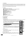
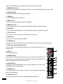
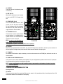
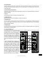
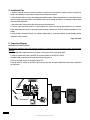
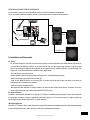
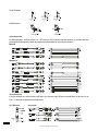
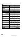
DJAP Series
HYBRID PORTABLE PA SYSTEM
User’s Manual
DJAP-612PB
DJAP-612PB
DJAP-615P
Safety Related Symbols
This symbol, wherever used, alerts you to the
presence of uninsulated and dangerous voltages within
the product enclosure. These are voltages that may be
sufficient to constitute the risk of electric shock or
death.
This symbol, wherever used, alerts you to important
operating and maintenance instructions.
'sinstructions.To avoid the risk of electric shock and
damage, do notsubject this product to any liquid/rain
or moisture.Do not use this product when in close
proximity to water.Do not install this product near any
direct heat source.Do not block areas of ventilation.
Failure to do so could result in fire.Keep product away
from naked flames.
IMPORTANT SAFETY INSTRUCTIONS
Read these instructionsFollow all instructions Keep
these instructions. Do not discard.Heed all warnings.
Only use attachments / accessories specified by
themanufacturer.
Power Cord and Plug
Do not tamper with the power cord or plug. These
redesigned for your safety.Do not remove Ground
connections! If the plug does not fit your AC out let
seek advicefrom a qualified electrician.Protect the
power cord and plug from any physical stress to avoid
risk of electric shock.Do not place heavy objects on
the power cord. This could cause electric shock or
fire.
Please read.
Protective Ground Terminal
AC mains (Alternating Current)
AC mains (Alternating Current)
Denotes the product is turned on.
Denotes the product is turned off.
WARNING
Describes precautions that should be observed to
prevent the possibility of death or injury to the user.
CAUTION
Describes precautions that should be observed to
prevent damage to the product.Disposing of this
product should not be placed in municipal waste but
rather in a separate collection.
WARNING Power Supply
Ensure that them a inssource voltage (AC outlet)
matches the voltage rating of the product. Failure
to do so could result in damage to the product and
possibly the user. Unplug the product before electrical
storms occur and when unused for long periods of
time to reduce the risk of electric shock or fire.
External Connection
Always use proper ready-made insulated mains cabling
(power cord). Failure to do so could result in shock/
death or fire. If in doubt, seek advice from a registered
electrician.
Cleaning
When required, either blow off dust from the productor
use a dry cloth.Do not use any solvents such as
Benzol or Alcohol.For safety, keep product clean and
free from dust.
Servicing
Refer all servicing to qualified service personnel
only. Do not perform any servicing other than those
instructions contained within the User's Manual.
PORTABLECarts and stands - The component should
be used
CART WARNING
only with a cart or stand that is recommended by the
manufacturer. A component and cart combination
should be moved with care. Quick stops, excessive
force, and uneven surfaces may cause the component
and cart combination to overturn.
Do Not Remove Any Covers
Within the product are areas where high voltages may
present. To reduce the risk of electric shock do not
remove any covers unless the AC mains power cord
is removed. Covers should be removed by qualified
service personnel only.
No user serviceable parts inside.
Fuse
To prevent fire and damage to the product, use only
the recommended fuse type as indicated in this
manual. Do not short-circuit the fuse holder. Before
replacing the fuse, make sure that the product is OFF
and disconnected from the AC outlet.
Protective Ground
Before turning the unit ON, make sure that it is
connected to Ground. This is to prevent the risk of
electric shock.Never cut internal or external Ground
wires. Like wise, never remove Ground wiring from the
Protective Ground Terminal.
Operating Conditions
Always install in accordance with the manufacturer
DJAP-612PB DJAP-615P
Table of Contents
INTRODUCTION ----------------------------------------------------------------------------------------------------------------------------------------------------------------------4
FEATURES ---------------------------------------------------------------------------------------------------------------------------------------------------------------------------- 4
CONTROL ELEMENTS -------------------------------------------------------------------------------------------------------------------------------------------------------------4
INSTALLATION TIPS ------------------------------------------------------------------------------------------------------------------------------------------------------------10
CONNECTION DIAGRAM -----------------------------------------------------------------------------------------------------------------------------------------------------10
INSTALLATION AND CONNECTION -----------------------------------------------------------------------------------------------------------------------------------------11
PRESET LIST --------------------------------------------------------------------------------------------------------------------------------------------------------------------------13
BLOCK DIAGRAM --------------------------------------------------------------------------------------------------------------------------------------------------------------13
TECHNICAL SPECIFICATIONS --------------------------------------------------------------------------------------------------------------------------------------------14
GUARANTEE ----------------------------------------------------------------------------------------------------------------------------------------------------------------------15
DJAP-612PB DJAP-615P
1. Introduction
Thank you for purchasing the DJAP 2-way vented powered speaker system. This unique system was designed to be an all-in
one portable solution with built-in High Power amplifier, 4 channels mixer with 3-band EQ and 24-bit DSP effects. The DJAP
combines practicality with top design concepts achieved over many years of manufacturing quality products. Please read this
manual carefully so you can take advantages of all the features of the DJAP.
2. Features
l Portable plywood painted cabinet with wheel
l1 x 12" (DJAP-612PB) /1 x 15"(DJAP-615P)woofer and 1 x 1" throat compression driver
l 4 channels mixer with a total of 4 inputs, Balanced XLR & TRS inputs
l 7-band graphic EQ
l Ultra low noise discrete MIC pre-amps with +15V phantom power
l 3-band EQ on all input channels
l Independent level controls on each channel
l High headroom for excellent dynamic range
l On-stage monitor mix
l DSP/FX send for built-in or external effects
l Tape In/Out
l 24-bit DSP effects with 100 presets
l USB-MP3 function
l Mini plug input for portable players with level control
3. Control Elements
3.1 MIXER SECTION
1. MONO INPUT Channels
CH1 through CH4, come with balanced MIC IN and LINE INconnectors. Use the XLR (MIC IN) socket to connect a
lowimpedance microphone or low level signal, which also features+15V phantom
power allowing you to connect a condensermicrophone.Use the 1/4" TRS (LINE IN)
8
jack to connect either a microphone or aline level instrument such as synthesizers,drum
5
machines, effect processors or any other line level signal.
Note: You shall never connect an unbalanced microphone to XLR socket if you do not
6
want to damage both the microphone andunit.
2. +15V PHANTOM POWER Switch
This switch will apply +15 Volt phantom power only to the 4 XLRinput sockets. When
these XLR sockets are connected with devices that do not require phantom power, please
make sure the phantom power is turned off, otherwise, this may damage thedevice and
monitor.
3. Channel LEVEL Control
This control isused to adjust the overall level of volume for respective channel. The
adjustable range goes from - to +10dB.
4. DSP/FX AUX1 POST Control
This control is configured as a POST-FADER, so the audio signalwill be affected by the
channel level control. Via the FX SEND jack,the AUX1 signal can be sent to an external
DJAP-612PB DJAP-615P
7
4
3
1
effect device.
QUALIZER
The UPA features a 3-band equalizer which allows you to adjust the high, mid and low frequencies separately on each mono
channel.
5. HIGH
This is the treble control. You can use it to get rid of high frequency noises or to boost the sound of cymbals or the high
harmonics of the human voice. The gain range goes from -15 dB to +15dB with a center frequency of 12kHz.
6. MID
This is the mid range control. It can affect most fundamental frequencies of all musical instruments and human voice. An
attentive use of this control will give you a very wide panorama of sound effects. The gain range goes from -12dB to +12dB
with a center frequency of 2.5kHz.
7. LOW
This is the bass control. It is used to boost male voice or kick-drum and bass guitar. Your system will sound much bigger than
what it is.The gain range goes from -15dB to +15dB and the center frequency is 80Hz.
8. PEAK LED
This LED will illuminate red when the signal nears clipping.
9. LEVEL Control
This control is used to adjust the level of TAPE IN and 3.5 φ jack signal simultaneously. The adjustable range goes from to+10dB.
14 34 30 36
29
10. 3.5 φ Jack
This insert can be used to connect with a Computer, MP3, MP4 or
CD players.
2
11. TAPE IN
The UPA features dual RCA jacks (left and right). If you wish to
listen to your monitor from a tape recorder, DAT or cassette, please
use these tape input jacks.
33
31
32
37
14
16
12. REC OUT
Via these jacks, you can route the main out signal into a tape
recorder or DAT for recording.
13. MONITOR Control
This control isused to adjust the level of monitor output.
17
35
13
9
15
10
19
18
14. GRAPHIC EQ
Your DJAP is equipped with a graphic EQ, which provides 7-band
fader controls. Via these faders, you can boost or attenuate the
selected frequency by 15dB at a preset band width.When all faders
are at the center position, the output of the equalizer is at the flat
response. They are used to modify the frequency "contour" of a
20
21
11
12
DJAP-612PB DJAP-615P
sound. The EQ function will be activated automatically as soon as you operate your DJAP .
15. MAIN MIX LEVEL Control
This control is used to adjust the overall volume of the main mix output. The adjustable range goes from -
to +10dB.
16. OUTPUT LEVEL LED
The 4-segment LED meter is used to indicate the output level.
17. POWER LED
This LED lights up when the unit is powered on.
18. MAIN OUT Jack
This jack is used to output the main mix signal to an external unit.
19. MONITOR OUT Jack
This jack is used to connect the input signal of an external monitor amplifier or active monitor speaker.
20. FOOTSWITCH
You can connect an external footswitch to turn the onboard effect module on/off, via the 1/4" phone jack.
21. USB PLAY-PAUSE
You can connect an external footswitch to control MP3 player to play or pause.
22. FX SEND Jack
This jack is used to sent out the signal from AUX bus.
23. FX RETURN Jack
This jack is used to return the sound of an effect unit to the main mix. You can also use it as an extra auxiliary input.
3.2 DSP Section with 24-Bit Digital Effects
Your UPA features a special 100-preset digital effect, for further details please refer to the
following content.
24
24. DISPLAY
Displays the selected preset.
25. PROGRAM (PUSH)
Adjust this knob to select the right effect you wish to perform. There are total 100 options for
you: Vocal, Echo, Plate and versatile two-effect combination. When you are satisfied with the
chosen preset, please push this knob to store this preset.
26. DSP MUTE Button
This button is used to activate/deactivate the effect facility. Sometimes, you can also use the
FOOTSWITCH jack for convenient operation.
27. CLIP/MUTE LED
This LED lights up when the input signal is too strong. In case of the digital effect module being
muted, this LED also lights up.
28. AUX/DFX RET Control
This control is used to adjust the volume of FX RETURN and MAIN OUTPUT effect.
DJAP-612PB DJAP-615P
25
27
26
28
22
23
3.3.USB-MP3 player section
29. USB PORT
For connecting with USB memory.
30. SD CARD PORT
For connecting with SD CARD memory.
31. PRE
In pause state, press this button it will go to the previous song and keep in pause state. In play+ state, press this button it will
go to the previous song and start playing.
32. NEXT
In pause state, press this button it will go to the next song and keep in pause state. In play state, press this button it will go to
the next song and start playing.
33. REPEAT
Press this button the player will change between the following four modes. REP ALL means to repeat all songs in the memory,
the mark on the LED is ALL . REP1 means to repeat one song, the mark on the LED is 1 .Play in order means to play the songs
according to the order, the mark on the screen is blank. Random play means to play the songs at random, the mark on the screen
is A.
34. PLAY/PAUSE
In play state, press PLAY/PAUSE button to pause the player. In pause state, press PLAY/PAUSE button to start playing.
35. STOP
In play state, press STOP button to stop playing and the whole quantity of MP3 songs in the USB memory will display on the
screen. In stop state, press the PRE/NEXT button or press the STOP button again to go to the first song and the player will keep
in pause state, then press down the PLAY/PAUSE button to play it.
36. POWER
When the unit is off, press this button hold for about 2 or 3 seconds to turn on the power supply of the player. Repeat the above
operation, you can turn off the power supply of the player.
37. USB OUTPUT
With this switch, the signal of USB can be selected to input in to CH4 or to TAPE.
3.4 REAR PANEL
38. POWER ON/OFF Switch
This switch is used to turn the unit on/off.
39. AC INPUT
Standard IEC receptacle, connect your DJAP to the main electrical outlet with the supplied power cord.
40. VOLTAGE SELECTOR
There are two kinds of voltages for your operation from this switch, you can select the voltage at 115V or 230V.
41. DC POWER Switch
Connect the AC supply and turn the DC power switch on, the battery can be charged.
DJAP-612PB DJAP-615P
42. BATTERY
These LEDs are used to indicate the power
of the battery.
43. EXT. DC 12V
When the AC and battery are out of power,
you can use the EXT. DC 12V supply to the
unit.
44. POWER AMP. Switch
Turn the Power AMP switch on "OFF"
position, the EXT. DC output will be cut
off, and the battery will store the power;
this switch on "ON" position, the EXT. DC
supply will work on normal condition.
47
47
46
45
43
41
44
46
48
42
40
45. SPEAKON Connector
This connector is used to connect with the 28
passive speakers. It is configured with a
39
speakon connector. You can determine the
signal that is out put to this jack.
NOTE: In order to avoid damaging your
DJAP-612PB
built-in amplifier, please pay more attention
to the impedance of speaker. Lower load impedances are not permitted.
40
38
39
DJAP-615P
46. CLIP LED
When the output signal distortion exceeds 0.5%, then the red LED (Clip) indicator will blink. It will warn you that the levels of
the input signal are too high and may cause distortion. Please attenuate the level of the input signal.
47. TO MIXER
Put the Mixer on the bracket to adjust the volume, you can insert the connector into the TO MIX jack, and the unit can work on
normal condition.
48. PHONE Jack & SPEAKON Connector
These jacks are used to connect UPA-615 passive speakers. They are configured with a speakon connector and 1/4” phone jack.
You can determine the signal that is outputted to these jacks.
NOTE: In order to avoid damaging your built-in amplifier, please pay more attention to the impedance of speaker. Lower load
impedances are not permitted.
3.5 WIRELESS MICROPHONE SYSYTEM
Diversity Receiver
49. Antenna
The antenna receives signal from transmitter. Make sure the antenna is fully extended vertically for receiving best effect. Fold
both antennas inward for the convenience of transporting.
DJAP-612PB DJAP-615P
50. AF-LEVEL Indicator
These LEDs indicate the incoming status of the audio signal. The four green LEDs light up indicate normal condition. When the
audio signal from microphone approaches clipping level the red LED indicator lights up, If no LED lights up, there is little or even
no signal being received.
51. MIC. ON & Diversity Signal Indicator
These indicators light up during standby. When microphone signal is received, the A or B signal indicator lights up to indicate the
reception of microphone.
52. MIC. ON
The LEDs indicate the reception of microphone 1 and microphone 2 alone.
53. POWER ON Indicator
When the unit powered on, this blue LED will lights up. It indicates the receiver is on.
54. SQUELCH Control
This control is SQ noisy controlled adjustment. The job of squelch circuit is to reduce audible noise. It eliminates noise during
pause in the audio signal by muting the receiver. Before you turn on the receiver, please adjust SQ control until the jamming
signal has disappeared. (Clockwise)
55. VOLUME Control
This knob sets the output audio signal level. Turn the knob fully clockwise for the maximum volume; and turn the knob fully
counterclockwise for the minimum volume.
56. TO CH1 & TO MAIN Switch
From this switch you can choose the microphone signal sent to CH1 or to MAIN. Switching it to “TO CH1”position, the signal
will come through CH1, after it is adjusted by the 3-band
EQ and DSP/FX control, then sent to main channel, you
can also adjust the signal by using the 7-band graphic
EQ and the DSP processor, then sent to the MAIN OUT.
49
Switching it to “TO MAIN” position, the signal will only
go to the main channel, after adjusted by the 7-band
50
graphic EQ and the DSP processor, then sent to MAIN
OUT.
51
57. MIC1 TO CH1/MIC2 TO CH2 & TO MAIN Switch
From this switch you can choose the microphone signal
sent to CH1/CH2 or to MAIN. Switching it to “MIC1
TO CH1/MIC2 TO CH2”position, the signal will come
through CH1/CH2, after it is adjusted by the 3-band
EQ and DSP/FX control, then sent to main channel, you
can also adjust the signal by using the 7-band graphic
EQ and the DSP processor, then sent to the MAIN OUT.
Switching it to “TO MAIN” position, the signal will only
go to the main channel, after adjusted by the 7-band
graphic EQ and the DSP processor, then sent to MAIN OUT.
52
53
54
55
56
57
With two microphone
With one microphone
DJAP-612PB DJAP-615P
4. Installation Tips
1- Speakers should be placed in a position that allows for unobstructe sound projection. In many instances is beneficial for
speakers to be elevated on tripod stands to achieve maximum dispersion and reach.
2- Use professional advice or service when hanging and installing speakers. Please take precautions to secure them to prevent
them from falling and hurting someone. Care should be taken as to not damage the cabinet or its components. Please comply
with all pertinent Regulations.
3- Use quality cables. Using quality cables will ensure the best possible sound.
4- For best results match the speakers to a good amplifier that matches the wattage and impedance of your speakers.
Proper amplification power results in good quality audio and longer component life. Check out the power requirement for your
cabinet.
5- Avoid pointing a microphone directly at an amplified speaker doing so, could cause feedback possibly damaging speaker
components and your hearing.
Enjoy the sound!
5. Connection Diagram
MATCHING WITH PASSIVE SPEAKER
Make all initial connections with all the equipment powered off, and make sure that the main volume controls are turned down
completely.
1) With a high quality signal line connect a CD player or other players to the active speaker DJAP.
2) Using the speaker cable connect the INPUT of the passive speaker to the OUTPUT of DJAP.
3) Complete other connections as illustrated. And then turn the power on.
4) Turn up the volume controls of the DJAP to about 70%.
5) Use the mixer PFL function of the DJAP to get the proper input level, and adjust the Main Mix Level control to manipulate
the output level.
Speaker
Cable
OF F
PASSIVE SPEAKER
10
DJAP-612PB DJAP-615P
MATCHING WITH PASSIVE SPEAKER & SUBWOOFER
In this example, it connects a sub-woofer, and the woofer of this two full-range act like midwoofer.
This is very popular combination especially in small size clubs where there is no need for two sub-woofers.
Speaker
Cable
OF F
PASSIVE SPEAKER
From Monitor Out
6. Installation and Connection
6.1 Set-up
Ok, you have reached this point and you are now in the position to successfully operate your DJAP. However, we advise you
to read carefully the following section to be the real master of your unit. Not paying enough attention to the input signal
level, to the routing of the signal and the assignment of the signal will result in unwanted distortion, a corrupted signal or no
sound at all. So you should follow this procedure for every single channel.
-Turn down all input and output controls.
-Connect phantom powered microphones before switching on the +15V phantom power switch.
-Set the output level of your DJAP at no more than 75%.
- Now, set the MONITOR level at no more than 50%. In this way you will be able to hear later what you are doing by
connecting a pair of powered monitor speakers.
-Position EQ controls on middle position.
-Now repeat the same sequence for all input channels. The main LED meter could move up into the red section. In this case
you can adjust the overall output level through the OUTPUT LEVEL control.
6.2 Audio Connection
The DJAP is presented with balanced XLR sockets & 1/4" TRS jacks and unbalanced RCA connectors, and it can be interfaced
in several ways to support a variety of applications without any signal loss. The unit can be used on a single instrument by
connecting to a mixing console's main inserts, or a power amplifier.
-Wiring Configuration
Either the 1/4" TRS phone jack or the XLR connector can be wired in balanced and unbalanced modes, which will be determined
by the actual application status, please wire your system as the following wiring examples:
11
DJAP-612PB DJAP-615P
For1/4"PhoneJack
ForXLRConnector
-In line Connection
For these applications, the DJAP provides 1/4" TRS connectors, XLR connectors and RCA connectors to interface with most
professional audio devices easily. Follow the configuration examples below for your particular connection.
Balanced
Unbalanced
-In line Connection
If you are connecting to a mixing console's main inserts, you may have single TRS jack for Send & Return. In this case, use an
insert "Y" cable that configured like the example below.
1/4" TRS Insert
Insert Leads
12
DJAP-612PB DJAP-615P
1
DJAP-612PB DJAP-615P
1
2
3
LEVEL
2
3
1
2
MP3 SW
3
1
RF SW
Wireless MIC TO MAIN
7-BAND GEQ
MP3
Wireless MIC
MON LEVEL
MAIN LEVEL
FOOT SW
AMP
LIMITER
DISPLAY
1
2
3
1
2
3
1
2
3
1+
1-
REC
OUT
SP OUT OUT
2+
2-
R
L
FX SEND
MON OUT
MAIN OUT
70~79 80~89
90~99
MINI D3.5
R
L
MP3 TO TAPE
MP3 TO CH4
FOOT SW
Wireless MIC TO CH1
EFX
2
EFX LEVEL
LEVEL
CLIP
CHORUS REVERB
DELAY STEREO
DELAY MONO
REVERB HALL2
TAPE IN
FX RTN
OUT
99 BAND PROGRAM
DSP
HIGH MID LOW
TONE
1
30~39 40~49 50~59
60~69 2
HA
CHANNEL1_4
REVERB HALLS
REVERB PLATES
ECHO REVERB
Preset
3
CH1-4
+15V
PHANTOM
EFX
EFX
2
MAIN
00~09
10~19 20~29 MAIN
No.
1
7. Preset List
REVERB ROOM
ECHO
SPECTIAL
8. Block Diagram
13
9. TECHNICAL SPECIFICATIONS
SPECIFICATIONS
DJAP-612PB
DJAP-615P
bal Mic/Line channels in
4
4
Tape in
1 RCA in+1 Mini ST in
1 RCA in+1 Mini ST in
Fx RTN in
1
1
Main out
1
1
Monitor out
1
1
Fx send
1
1
REC out
1
1
MIC TO MAIN/MON
50dB
50dB
GAIN
LINE TO MAIN/MON
30dB
30dB
FREQUENCY RESPONSE(-1dB)
20Hz-20KHz
20Hz-20KHz
MIC IN
2K
2K
Impedance
LINE IN
20K
20K
TAPE IN
10K
10K
MAIN/MON OUT
1.5K
1.5K
ALL MAX OUT
22dBu
22dBu
S/N
>80dB
>80dB
THD
<0.1%
<0.1%
3 band(80/2.5K/12K)
3 band(80/2.5K/12K)
CH EQ
+/-15dB
+/-15dB
7 band EQ(63/160/400/1K/ 7 band EQ(63/160/400/1K/
Main EQ
2.5K/6.3K/16K) +/-12dB 2.5K/6.3K/16K) +/-12dB
DSP (Digital Effect)
99 preset programs(24-Bit) 99 preset programs(24-Bit)
Phantom Power(+15V)
MP3 (USB) +SD in
Wireless MIC
12''Woofer+1''Tweeter 15''Woofer+1''Tweeter
Speaker
Driver
Driver
Out Power (RMS)
120W
180W
+EXT speakers
200W
300W
SPEAKON Connector
12V Battery
×
Battery Charge time
6H
×
120/240V AC
Power Supply
120/240V AC
12V DC
14
DJAP-612PB DJAP-615P
10. GUARANTEE
AUDIOPIPE guarantees the normal operation of the product against any defect of manufacture and / or vice of material, by the
term of 12 months, counted as of the date of purchase on the part of the user, committing itself to repair or to change, to its
election, without position some, any piece or component that will fail in normal conditions of use within the mentioned period.
This guarantee is valid if the original buyer will have to present/display this certificate properly sealed and signed by the selling
house, accompanied by the corresponding invoice of purchase where it consisted the model and serial number of the acquired
equipment.
The guarantee does not cover:
-Damages caused by the illegal use of the product, repair and/or nonauthorized modification conducted by people by
AUDIOPIPE.
- Damages caused by the connection of the equipment to other equipment different from the specified ones in the manual of
use, or by bad connection to these last ones.
- Damages caused by electrical storms, blows and/or incorrect transport.
-Damages caused by excesses or falls of tension in the network or by connection to networks with a tension different from
the required one by the unit.
-Damages caused by the presence of sand, acid of batteries, water, or any strange element inside the equipment.
-Deteriorations produced by the course of the time, use and/or normal wear of the unit.
-Alteration or absence of the serial number of factory of the equipment.
The repairs could only be carried out the authorized technical service by AUDIOPIPE, that will inform about the term and
other details into the repairs to take place according to this guarantee.
AUDIOPIPE, will repair this unit in counted a term nongreater to 30 days as of the date of entrance of the unit to the Technical
Service. In those cases in that due to the particularitity of the spare part, outside necessary their import, the repair time and the
viability of the same one will be subject to the effective norms for the import of parts, in which case one will inquire to the user
about the term and possibility into repair.
With the object of its correct operation, and of the validity of this one guarantee, this product will have to be installed and to be
used according to the instructions that are detailed in the manual associate or the package of the product.
This unit will be able to appear for its repair, next to the invoice of purchase (or any other proof where the date of purchase
consists), to its authorized distributer AUDIOPIPE or an authorized technical center on watch by AUDIOPIPE.
Exclusion of damages:
THE RESPONSABILITY OF AUDIOPIPE BY ANY DEFECTIVE PRODUCT IS LIMITED THE REPAIR OR THE REPLACEMENT OF HE
HIMSELF, TO AUDIOPIPE. IF WE CHOSE TO REPLACE THE PRODUCT, THE REPLACEMENT CAN BE A RECONDITIONATED
UNIT. AUDIOPIPE WILL NOT BE RESPONSIBLE BY THE DAMAGES BASED ON THE LOST, INCONVENIENCE, LOSS OF USE,
BENEFITS, LOST SAVINGS, BY THE DAMAGE TO OTHER EQUIPMENT OR OTHER ARTICLES IN THE USE SITE, OR BY ANY
OTHER DAMAGE IF HE IS FORTUITOUS, CONSEQUENT OR OF ANOTHER TYPE, ALTHOUGH AUDIOPIPE HAS BEEN NOTICED
OF THE POSSIBILITY OF SUCH DAMAGES.
Some states do not allow to the exclusion or the limitation to the fortuitous or consequent damages, so the aforesaid limitation
can not be applied to you.This guarantee gives specific legal rights him, you you can also have other right that varies of state to
state.
15
DJAP-612PB DJAP-615P