1
TECHNICAL BULLETIN
[Issue No.] FA-A-0171
[Page] 1/62
[Title] Differences between MELSEC-Q series and MELSEC iQ-R series
[Date of Issue] November 2014
[Relevant Models] MELSEC iQ-R series
Thank you for your continued support of Mitsubishi programmable controllers, MELSEC-Q series.
This bulletin provides differences between MELSEC-Q series and MELSEC iQ-R series.
Note that the reference manuals or the references described in this bulletin are information as of September 2014.
Contents
GENERIC TERMS ·························································································································· 2
1 DIFFERENCES BETWEEN MELSEC-Q SERIES AND MELSEC iQ-R SERIES ············································ 3
1.1 Configurable Devices ················································································································ 3
1.2 CPU Modules (QnUDVCPU and RCPU)························································································· 4
1.2.1 Instructions ······················································································································· 4
1.2.2 Parameters ························································································································ 8
1.2.3 Devices and files················································································································ 12
1.2.4 Functions ························································································································ 17
1.3 Power Supply Modules, Base Units, I/O Modules ·············································································· 26
1.3.1 Power supply modules ········································································································· 26
1.3.2 Base units ························································································································ 26
1.3.3 I/O modules ····················································································································· 26
1.4. Intelligent Function Modules······································································································ 27
1.4.1 Analog-digital converter modules···························································································· 27
1.4.2 Digital-analog converter modules ···························································································· 28
1.4.3 Simple motion modules ······································································································· 29
1.4.4 Positioning modules············································································································ 30
1.4.5 High-speed counter modules·································································································· 31
1.5. Communication Modules and Network Modules ·············································································· 32
1.5.1 Common items for communication modules and network modules ···················································· 32
1.5.2 Ethernet interface modules ···································································································· 34
1.5.3 CC-Link IE Field Network master/local modules ········································································· 41
1.5.4 CC-Link system master/local modules ······················································································ 43
1.5.5 Serial communication modules ······························································································· 44
2 SPECIFICATIONS DIFFERENCES BETWEEN MELSEC-Q SERIES AND MELSEC iQ-R SERIES ·················· 46
2.1 CPU Modules (QnUDVCPU and RCPU)························································································ 46
2.2 Power Supply Modules, Base Units, I/O Modules ·············································································· 50
2.3. Intelligent Function Modules······································································································ 51
2.3.1 Analog-digital converter modules···························································································· 51
2.3.2 Digital-analog converter modules ···························································································· 52
2.3.3 Positioning modules············································································································ 53
2.3.4 High-speed counter modules·································································································· 54
2.4. Communication Modules and Network Modules ·············································································· 56
2.4.1 Ethernet interface modules ···································································································· 56
2.4.2 CC-Link IE Field Network master/local modules ········································································· 59
2.4.3 CC-Link system master/local modules ······················································································ 62
2.4.4 Serial communication modules ······························································································· 62
HEAD OFFICE : TOKYO BUILDING, 2-7-3 MARUNOUCHI, CHIYODA-KU, TOKYO 100-8310, JAPAN
NAGOYA WORKS : 1-14, YADA-MINAMI 5-CHOME, HIGASHI-KU, NAGOYA, JAPAN
TECHNICAL BULLETIN
[Issue No.] FA-A-0171
[Page] 2/62
[Title] Differences between MELSEC-Q series and MELSEC iQ-R series
[Date of Issue] November 2014
[Relevant Models] MELSEC iQ-R series
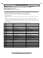
GENERIC TERMS
Generic term
Description
RCPU
A generic term for the R04CPU, R08CPU, R16CPU, R32CPU, and R120CPU
QnUDVCPU
A generic term for the Q03UDVCPU, Q04UDVCPU, Q06UDVCPU, Q13UDVCPU, and Q26UDVCPU
HEAD OFFICE : TOKYO BUILDING, 2-7-3 MARUNOUCHI, CHIYODA-KU, TOKYO 100-8310, JAPAN
NAGOYA WORKS : 1-14, YADA-MINAMI 5-CHOME, HIGASHI-KU, NAGOYA, JAPAN
TECHNICAL BULLETIN
[Issue No.] FA-A-0171
[Page] 3/62
[Title] Differences between MELSEC-Q series and MELSEC iQ-R series
[Date of Issue] November 2014
[Relevant Models] MELSEC iQ-R series
1. DIFFERENCES BETWEEN MELSEC-Q SERIES AND MELSEC iQ-R SERIES
This chapter describes the differences between MELSEC-Q series and MELSEC iQ-R series.
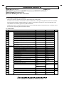
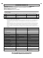
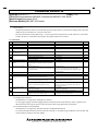
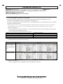
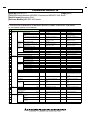
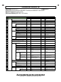
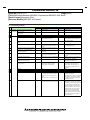
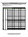
1.1 Configurable Devices
This section provides the list of configurable devices in the MELSEC-Q series system and the MELSEC iQ-R series
system.
For details on the applicable modules in the MELSEC iQ-R series system, refer to the MELSEC iQ-R Module
Configuration Manual (SH-081262ENG). Pay attention to the power capacity in selecting a model because the current
consumption differs between MELSEC iQ-R series and MELSEC-Q series. Please visit the following website to check
the power capacity:
www.mitsubishielectric.co.jp/fa/ssl/products/cnt/plcr/ex/select/rselsystem/rselsystem.html
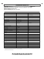
No.
Item
MELSEC-Q series
1
Programmable controller CPU
2
Motion CPU
Q03UDVCPU/Q04UDVCPU/Q06UDVCPU/Q13UDVCPU/ R04CPU/R08CPU/R16CPU/R32CPU/R120CPU
Q26UDVCPU
Q172DSCPU/Q173DSCPU
R16MTCPU/R32MTCPU
MELSEC iQ-R series
3
SD memory card
L1MEM-2GBSD/L1MEM-4GBSD
L1MEM-2GBSD/L1MEM-4GBSD
4
Extended SRAM cassette
NZ2MC-1MBS/NZ2MC-2MBS/NZ2MC-4MBS/
NZ2MC-8MBS
R35B/R38B/R312B
R65B/R68B/R612B
5
Main base unit
Q4MCA-1MBS/Q4MCA-2MBS/Q4MCA-4MBS/
Q4MCA-8MBS
Q35DB/Q38DB/Q312DB
6
Extension base unit
Q65B/Q68B/Q612B
7
Extension cable
QC06B/QC12B/QC30B/QC50B
RC06B/RC12B/RC30B/RC50B
8
Power supply module
Q61P/Q63P
R61P/R63P
9
Input module
QX10/QX40/QX40-TS/QX40-S1/QX41/QX41-S1/QX42/
QX42-S1/QX80/QX80-TS/QX81/QX82/QX82-S1
RX10/RX40C7/RX41C4/RX42C4
10
11
Interrupt module
Output module
RX40C7
RY10R2/RY40NT5P/RY41NT2P/RY42NT2P/RY40PT5P/
RY41PT1P/RY42PT1P
RH42C4NT2P
R60AD4/R60ADV8/R60ADI8
12
I/O combined module
QI60
QY10/QY10-TS/QY40P/QY40P-TS/QY41P/QY42P/QY80/
QY80-TS/QY81P/QY82P
QH42P
13
Analog input module
Q64AD/Q68ADV/Q68ADI
14
Analog output module
64DAN/Q68DAVN/Q68DAIN
R60DA4/R60DAV8/R60DAI8
15
Simple motion module
QD77MS2/QD77MS4/QD77MS16
RD77MS2/RD77MS4/RD77MS8/RD77MS16
16
Positioning module
QD75P2(N)/QD75P4(N)/QD75D2(N)/QD75D4(N)
RD75P2/RD75P4/RD75D2/RD75D4
17
High-speed counter module
QD62/QD62E/QD62D
RD62P2/RD62P2E/RD62D2
18
Ethernet interface module
QJ71E71-100
RJ71EN71
19
CC-Link IE Controller Network
module
QJ71GP21-SX
RJ71GP21-SX
20
21
CC-Link IE Field Network module
CC-Link module
QJ71GF11-T2
QJ61BT11N
RJ71GF11-T2
RJ61BT11
22
23
Serial communication module
GOT
QJ71C24N/QJ71C24N-R2/QJ71C24N-R4
GOT2000/GOT1000
RJ71C24/RJ71C24-R2/RJ71C24-R4
GOT2000/GOT1000
24
25
MELSEC iQ-R series module
MELSEC-Q series module
Not supported
Supported
Supported
Supported *1
26
27
MELSEC-A series module
Engineering software
Supported
GX Works2/GX Developer
Not supported
GX Works3
*1 For the applicable modules, refer to the MELSEC iQ-R Module Configuration Manual (SH-081262ENG).
HEAD OFFICE : TOKYO BUILDING, 2-7-3 MARUNOUCHI, CHIYODA-KU, TOKYO 100-8310, JAPAN
NAGOYA WORKS : 1-14, YADA-MINAMI 5-CHOME, HIGASHI-KU, NAGOYA, JAPAN
TECHNICAL BULLETIN
[Issue No.] FA-A-0171
[Page] 4/62
[Title] Differences between MELSEC-Q series and MELSEC iQ-R series
[Date of Issue] November 2014
[Relevant Models] MELSEC iQ-R series
1.2 CPU Modules (QnUDVCPU and RCPU)
This section describes the differences between the QnUDVCPU and the RCPU.
For details on the instructions for the RCPU, refer to the MELSEC iQ-R Programming Manual (Instructions, Standard
Functions/Function Blocks) (SH-081266ENG). For details on the functions and devices, refer to the MELSEC iQ-R
CPU Module User's Manual (Application) (SH-081264ENG).
QnUDVCPU projects created by using GX Works2 can be opened and edited by using GX Works3. For details, refer to
the GX Works3 Operating Manual (SH-081215ENG).
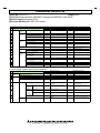
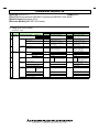
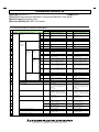
1.2.1 Instructions
No.
Classification
1
2
3
4
5
6
7
8
9
10
Basic
instruction
11
12
13
14
15
16
17
18
19
20
21
22
23
24
25
26
27
28
29
30
Application
instruction
Converting 16-bit binary data to 32-bit floating point type real number
34
35
RCPU
Reference
INT2FLT
(a)
Converting 32-bit binary data to 32-bit floating point type real number
DFLT
DINT2FLT
Converting 16-bit binary data to 64-bit floating point type real number
FLTD
INT2DBL
Converting 32-bit binary data to 64-bit floating point type real number
Converting 32-bit floating point type real number to 16-bit binary data
DFLTD
INT
DINT2DBL
FLT2INT
Converting 32-bit floating point type real number to 32-bit binary data
Converting 64-bit floating point type real number to 16-bit binary data
DINT
INTD
FLT2DINT
DBL2INT
Converting 64-bit floating point type real number to 32-bit binary data
Converting 16-bit binary data to 32-bit binary data
DINTD
DBL
DBL2DINT
INT2DINT
Converting 32-bit binary data to 16-bit binary data
Converting 32-bit floating point type real number to 64-bit floating point
type real number
Converting 64-bit floating point type real number to 32-bit floating point
type real number
Converting hexadecimal ASCII code to 16-bit binary data
WORD
ECON
DINT2INT
FLT2DBL
EDCON
DBL2FLT
HEX
ASC2INT
Converting 16-bit binary data to hexadecimal ASCII code
ASC
INT2ASC
Calculating the square root of floating-point data (single precision)
SQR
ESQRT
Calculating the square root of floating-point data (double precision)
SQRD
EDSQRT
Calculating the square root of BCD 4-digit
BSQR
BSQRT
Calculating the square root of BCD 8-digit
Ramp signal instruction
BDSQR
RAMP
BDSQRT
RAMPQ
Searching 16-bit binary data
Searching 32-bit binary data
SER
DSER
SERDATA
DSERDATA
Sorting 16-bit binary data
Sorting 32-bit binary data
SORT
DSORT
SORTD
DSORTD
Converting time data from hour/minute/second to second
Converting time data from second to hour/minute/second
SECOND
HOUR
TIME2SEC
SEC2TIME
Reading 32-bit binary data (buffer memory access)
Reading device comment
DFRO
COMRD
DFROM
Not supported
Setting a comment file name
High-speed block transfer of file register
QCDSET
RBMOV
BMOV
-
Selecting refresh to be performed
COM (without execution
condition)
COM (with execution
condition)
(c)
Writing data to host CPU shared memory
CCOM (with execution
condition)
TO/S.TO
TO
(d)
Reading module information
UNIRD
UNIINFRD
(e)
Disabling interrupt programs
DI (without execution
condition)
EI (without execution
condition)
DI (with execution
condition)
EI (with execution
condition)
(f)
31
32
33
QnUDVCPU
FLT
Enabling interrupt programs
HEAD OFFICE : TOKYO BUILDING, 2-7-3 MARUNOUCHI, CHIYODA-KU, TOKYO 100-8310, JAPAN
NAGOYA WORKS : 1-14, YADA-MINAMI 5-CHOME, HIGASHI-KU, NAGOYA, JAPAN
(b)
TECHNICAL BULLETIN
[Issue No.] FA-A-0171
[Page] 5/62
[Title] Differences between MELSEC-Q series and MELSEC iQ-R series
[Date of Issue] November 2014
[Relevant Models] MELSEC iQ-R series
(a) FLT, FLTD, HEX, ASC, and other instructions
Instruction names differ between the QnUDVCPU and the RCPU.
Names of instructions for the RCPU are changed so that the data status before and after conversion can be easily
understood from the name.
(b) QCDSET and COMRD instructions
The RCPU does not support the QCDSET and COMRD instructions.
Change the program so that a device comment is read and stored to the GOT. (Use a GOT connectable to the
RCPU.)
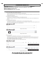
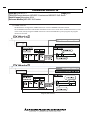
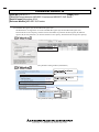
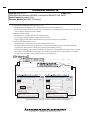
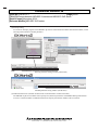
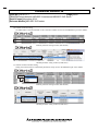
(c) CCOM and COM instructions
The RCPU does not support the CCOM instruction. Use the COM instruction instead.
An execution condition is given to the COM instruction for the RCPU. Therefore, the instruction operates in the
same way as the CCOM instruction for the QnUDVCPU.
Program (GX Works2)
Program (GX Works3)
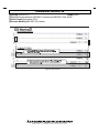
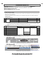
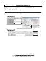
(d) S.TO instruction
The RCPU does not support the S.TO instruction. Use the TO instruction instead.
Since data are written at execution of the instruction, the completion device (D), which turns on for one scan
upon completion of the processing, is not provided for the TO instruction. If (D) is used in the MELSEC-Q
series program, the program needs to be corrected.
In the program example below, M0 is the completion device (D).
Program (GX Works2)
Program (GX Works3)
HEAD OFFICE : TOKYO BUILDING, 2-7-3 MARUNOUCHI, CHIYODA-KU, TOKYO 100-8310, JAPAN
NAGOYA WORKS : 1-14, YADA-MINAMI 5-CHOME, HIGASHI-KU, NAGOYA, JAPAN
TECHNICAL BULLETIN
[Issue No.] FA-A-0171
[Page] 6/62
[Title] Differences between MELSEC-Q series and MELSEC iQ-R series
[Date of Issue] November 2014
[Relevant Models] MELSEC iQ-R series
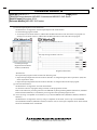
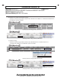
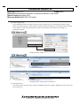
(e) UNIRD instruction
The RCPU does not support the UNIRD instruction. Use the UNIINFRD instruction instead.
The UNIINFRD instruction reads module information in units of two words. If the module information (in units
of one words) read by using the UNIRD instruction is used in the MELSEC-Q series program, the program
needs to be corrected.
Program (GX Works2)
Program (GX Works3)
HEAD OFFICE : TOKYO BUILDING, 2-7-3 MARUNOUCHI, CHIYODA-KU, TOKYO 100-8310, JAPAN
NAGOYA WORKS : 1-14, YADA-MINAMI 5-CHOME, HIGASHI-KU, NAGOYA, JAPAN
TECHNICAL BULLETIN
[Issue No.] FA-A-0171
[Page] 7/62
[Title] Differences between MELSEC-Q series and MELSEC iQ-R series
[Date of Issue] November 2014
[Relevant Models] MELSEC iQ-R series
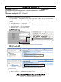
(f) DI and EI instructions
An execution condition is given to the DI and EI instructions for the RCPU.
For this reason, an instruction to skip the execution of these instructions, such as a jump instruction, is not
required. To execute these instructions every scan in the same way as those for the QnUDVCPU, set SM400
(Always ON) as an execution condition.
Program (GX Works2)
Program (GX Works3)
HEAD OFFICE : TOKYO BUILDING, 2-7-3 MARUNOUCHI, CHIYODA-KU, TOKYO 100-8310, JAPAN
NAGOYA WORKS : 1-14, YADA-MINAMI 5-CHOME, HIGASHI-KU, NAGOYA, JAPAN
TECHNICAL BULLETIN
[Issue No.] FA-A-0171
[Page] 8/62
[Title] Differences between MELSEC-Q series and MELSEC iQ-R series
[Date of Issue] November 2014
[Relevant Models] MELSEC iQ-R series
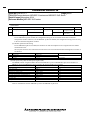
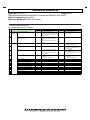
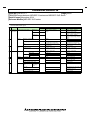
1.2.2 Parameters
No.
Item
QnUDVCPU
RCPU
Reference
1
CPU module
PLC parameter (PARAM.QPA)
(a)
2
Intelligent function
module
Intelligent function module parameter (IPARAM.QPA)
Module parameter (UNIT.PRM)
System parameter (SYSTEM.PRM)
CPU parameter (CPU.PRM)
Module parameter (UNIT.PRM)
Memory card parameter (MEMCARD.PRM)
Parameters of
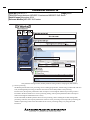
each module
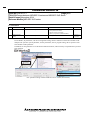
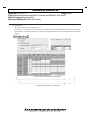
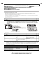
(a) CPU module
For the RCPU, set parameters, such as I/O assignment setting, that are common to all the CPU modules in the
multiple CPU system in system parameter, and set parameters, such as program setting, that is specific to each
CPU module in CPU parameter.
In addition, set unit parameters to use the built-in Ethernet function, and set memory card parameters to perform
boot operation.
PLC parameter setting window and Write to PLC window (GX Works2)
HEAD OFFICE : TOKYO BUILDING, 2-7-3 MARUNOUCHI, CHIYODA-KU, TOKYO 100-8310, JAPAN
NAGOYA WORKS : 1-14, YADA-MINAMI 5-CHOME, HIGASHI-KU, NAGOYA, JAPAN
TECHNICAL BULLETIN
[Issue No.] FA-A-0171
[Page] 9/62
[Title] Differences between MELSEC-Q series and MELSEC iQ-R series
[Date of Issue] November 2014
[Relevant Models] MELSEC iQ-R series
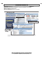
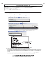
System parameter setting window, CPU parameter setting window, and Write to PLC window (GX
Works3)
HEAD OFFICE : TOKYO BUILDING, 2-7-3 MARUNOUCHI, CHIYODA-KU, TOKYO 100-8310, JAPAN
NAGOYA WORKS : 1-14, YADA-MINAMI 5-CHOME, HIGASHI-KU, NAGOYA, JAPAN
TECHNICAL BULLETIN
[Issue No.] FA-A-0171
[Page] 10/62
[Title] Differences between MELSEC-Q series and MELSEC iQ-R series
[Date of Issue] November 2014
[Relevant Models] MELSEC iQ-R series
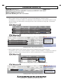
Built-in Ethernet function: TCP (MELSOFT connection)/UDP (MELSOFT connection) setting
For the RCPU, set connection numbers. Set “MELSOFT Connection Module” in the connection number not used.
The open setting is not required when connecting the GOT or other external devices using UDP. (An automatic
UDP port is used.)
Built-in Ethernet setting window of PLC parameter (GX Works2)
Module parameter setting window (GX Works3)
Built-in Ethernet function: TCP connection setting of socket communications (TCP/IP connection)
For the RCPU, select “Active Connection Module”, “Unpassive Connection Module”, or “Fullpassive Connection
Module” in the Ethernet device setting, and then set “Socket Communication” in “Communication Method”.
Built-in Ethernet setting window of PLC parameter (GX Works2)
Module parameter setting window (GX Works3)
HEAD OFFICE : TOKYO BUILDING, 2-7-3 MARUNOUCHI, CHIYODA-KU, TOKYO 100-8310, JAPAN
NAGOYA WORKS : 1-14, YADA-MINAMI 5-CHOME, HIGASHI-KU, NAGOYA, JAPAN
TECHNICAL BULLETIN
[Issue No.] FA-A-0171
[Page] 11/62
[Title] Differences between MELSEC-Q series and MELSEC iQ-R series
[Date of Issue] November 2014
[Relevant Models] MELSEC iQ-R series
Built-in Ethernet function: Broadcast communications setting of socket communications (UDP/IP connection)
For the RCPU, select “UDP Connection Module”, and then set “Broadcast Send” or “Broadcast Receive” in
“Communication Method”.
Built-in Ethernet setting window of PLC parameter (GX Works2)
Module parameter setting window (GX Works3)
Built-in Ethernet function: Time zone setting of time setting (SNTP client)
For the RCPU, set the time zone in “Operation Related Setting” of CPU parameter because the time zone can be set
in the clock data of the CPU module.
Module parameter setting window (GX Works3)
Built-in Ethernet setting window of PLC parameter
(GX Works2)
CPU parameter setting window (GX Works3)
Built-in Ethernet function: Setting for communications using the predefined protocol (predefined protocol operating
status storage device)
For the RCPU, check the predefined protocol operating status such as protocol execution status and protocol
execution count in the CPU buffer memory (U3En\G*). If the start device where the operating status of the
predefined protocol is stored is set in the open setting of PLC parameter and the device is used in the MELSEC-Q
series program, the program needs to be corrected.
HEAD OFFICE : TOKYO BUILDING, 2-7-3 MARUNOUCHI, CHIYODA-KU, TOKYO 100-8310, JAPAN
NAGOYA WORKS : 1-14, YADA-MINAMI 5-CHOME, HIGASHI-KU, NAGOYA, JAPAN
TECHNICAL BULLETIN
[Issue No.] FA-A-0171
[Page] 12/62
[Title] Differences between MELSEC-Q series and MELSEC iQ-R series
[Date of Issue] November 2014
[Relevant Models] MELSEC iQ-R series
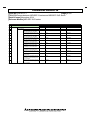
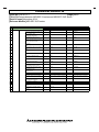
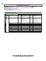
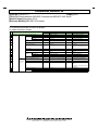
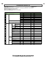
1.2.3 Devices and files
This section describes the specifications differences of devices and files used in the QnUDVCPU and the RCPU.
No.
Item
QnUDVCPU
RCPU
Reference
1
Special relay (SM) and special register (SD)
SM0 to SM2047, SD0 to SD2047
SM0 to SM4095, SD0 to SD4095
(a)
2
Extended data register (D) and extended link
register (W)
Extended data register (D) and extended link
register (W)
Not supported
(b)
Local device
M0, D0, and others
#M0, #D0, and others (Described with "#".)
(c)
File name
ASCII
Unicode
(d)
3
4
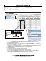
(a) Special relay (SM) and special register (SD)
The SM/SD number assignment differs between the QnUDVCPU and the RCPU. Also, some SM/SD areas are
used for different purposes. If SM/SD is used in the MELSEC-Q series program, the program needs to be
corrected.
When the QnUDVCPU project created by using GX Works2 is opened and edited by using GX Works3, the
SM/SD areas that have not been replaced in advance are automatically converted to the corresponding SM/SD
areas or CPU buffer memory (U3En\G*) assigned to the RCPU. If the area is converted to the CPU buffer
memory (U3En\G*), 'n' is fixed to CPU No.1. Change 'n' to the corresponding number as needed (for CPU No.2
to No.4).
Item
QnUDVCPU
Diagnostic error
SD0
RCPU
SD0
Clock time for diagnostic error occurrence
SD1 to SD3
SD1 to SD7 (Clock time for self-diagnostic error
occurrence)*1
Error common information and error individual
information
SM5, SM16
N/A
Error information category, error common information,
and error individual information
Error clear
SD4, SD5 to SD15, SD16 to SD26
SD80 to SD143 (Detailed information 1 and 2)*1
SD50, SM84, SD81 to SD85
N/A
Battery low
IP packet transfer function related information
SD51, SD52
SD180 to SD183
N/A
U3En\G310 to U3En\G313
Switch status and LED status
CPU module operating status
SD200, SD201
SD203
SD200, SD201
SD203
LED off command, LED color, and LED priority
PAUSE enable coil
SM202, SD202, SD204, SD207 to SD209
SM206
N/A
N/A
Clock data
LED display data
SD210 to SD213
SD220 to SD227
SD210 to SD216*1
N/A
Device range check inhibit flag
Base mode
SM237
SD240
N/A
N/A
Q series base unit connection status
CPU No.'n' error flag
SD242
SM244 to SM247
SD242 (Q series module mounting availability check)
SM230 to SM233
All stations refresh command
Device assignment
SM254
SD282 to SD311
N/A
SD260 to SD309
Latch clear function related information
Ethernet information
SM339, SD339
SD340 to SD368
N/A
N/A
Multiple CPU system information
Initial/minimum/maximum scan time, END processing
time, constant scan waiting time, scan program
execution time
SD393 to SD399
SD522 to SD523, SD524 to SD525, SD526 to SD527,
SD540 to SD541, SD542 to SD543, SD548 to SD549
SD228 to SD233
SD518 to SD519, SD522 to SD523, SD524 to SD525,
SD526 to SD527, SD528 to SD529, SD530 to SD531
Memory card usage status
SD604
SD604 (SD memory card usage status)
Drive 2 capacity (in increments of 1K or 1M bytes)
SD603, SD606, SD607
SD606, SD607 (SD memory card capacity (in
increments of 1K bytes))
HEAD OFFICE : TOKYO BUILDING, 2-7-3 MARUNOUCHI, CHIYODA-KU, TOKYO 100-8310, JAPAN
NAGOYA WORKS : 1-14, YADA-MINAMI 5-CHOME, HIGASHI-KU, NAGOYA, JAPAN
TECHNICAL BULLETIN
[Issue No.] FA-A-0171
[Page] 13/62
[Title] Differences between MELSEC-Q series and MELSEC iQ-R series
[Date of Issue] November 2014
[Relevant Models] MELSEC iQ-R series
Item
QnUDVCPU
RCPU
Memory card remove/insert enable flag
SM609
N/A
Drive 2 free space (in increments of 1M bytes)
SD616, SD617
Drive 3/4 related
SM620 to SM624, SD620
SD610, SD611 (SD memory card free space (in
increments of 1K bytes))
N/A
Drive 3 capacity (in increments of 1K bytes)
Drive 4 capacity (in increments of 1K bytes)
SD622
SD623
SD618, SD619
SD622, SD623
Drive 3/4 usage status
SD624
SD614 (Drive 3 usage status), SD620 (Drive 4 usage
status)
Directory batch delete
File register information
SM638, SD638, SD639
SM640, SD640 to SD647
N/A
N/A
File register block number
Comment file information
SD648
SM650, SD650 to SD656
SD312
N/A
Program memory/standard ROM write related
information
SM680 to SM682, SD681 to SD683, SM685 to SM687,
SD686 to SD688
SM628 to SM630, SD629 to SD631, SM632 to SM634,
SD633 to SD635
Execution count of the write instruction to the standard
ROM
Boot operation information
SD695
SD771
SM660, SD660 to SD666
N/A
Parameter-valid drive information
SD670
N/A
EI flag
SM715
N/A
Block comparison
SM716 to SM718
SM704
IMASK instruction mask pattern
SD715 to SD717, SD781 to SD793
SD1400 to SD1415
File being accessed
SM721
SM753
BIN/DBIN instruction error control flag
SM722
SM754
Scaling instruction search method setting
SM750
SM755
PID bumpless processing setting and PID limit setting
SM774, SD774, SD775
SM792, SD792, SD793
Accumulator
SD718, SD719
N/A
Refresh processing selection when the COM instruction
is executed
Auto logging status
SD778
SD775
SM841
N/A
Device information when the RAM error occurs
Remote password count
SD927, SD928
SD979 to SD999
N/A
U3En\G320 to U3En\G340
A to Q conversion
IP address being used
SM1000 to SM1255, SD1000 to SD1255
SD1260 to SD1265
N/A
U3En\G50 to U3En\G65 (Own node IP address)
MAC address
Time setting function (SNTP) related information
SD1266 to SD1268
SM1270, SD1270 to SD1275*1
U3En\G74 to U3En\G76 (Own node MAC address)
U3En\G290 to U3En\G299*1
Remote password mismatch count clear
Forced connection invalidation
SM1273
SD1276, SD1277
N/A
U3En\G280, U3En\G281
Open completion signal, open request signal, and receive SD1282, SD1284, SD1286
status signal
SD1504, SD1505, SD1506
Built-in Ethernet port connection status
SD1288
N/A
Ethernet basic timeout time
IP address change function related information
SD1289
SM1292 to SM1297, SD1292 to SM1299
N/A
SM1520 to SM1523, SD1520 to SD1527
Predefined protocol function related information
Built-in Ethernet port counter
SM1354, SM1355*2, SD1359 to SD1381
SD1395
U3En\G692, U3En\G710 to U3En\G729
U3En\G226 (Receive FIFO overflow count)
Fuse blown module
I/O module verification
SD1300 to SD1331
SD1400 to SD1431
N/A
N/A
Data logging
SM1940 to SM2037, SD1940 to SD2036
SM1210 to SM1307, SD1210 to SD1306
*1 Different types of data are stored in these areas of the RCPU. For this reason, when the QnUDVCPU project created by using GX Works2 is opened
and edited by using GX Works3, the areas are not converted automatically.
*2 SM1355 cannot be used in the RCPU.
HEAD OFFICE : TOKYO BUILDING, 2-7-3 MARUNOUCHI, CHIYODA-KU, TOKYO 100-8310, JAPAN
NAGOYA WORKS : 1-14, YADA-MINAMI 5-CHOME, HIGASHI-KU, NAGOYA, JAPAN
TECHNICAL BULLETIN
[Issue No.] FA-A-0171
[Page] 14/62
[Title] Differences between MELSEC-Q series and MELSEC iQ-R series
[Date of Issue] November 2014
[Relevant Models] MELSEC iQ-R series
(b) Extended data register (D) and extended link register (W)
The RCPU does not support the use of the extended data register (D) and extended link register (W).
Increase the device area capacity, and also increase the number of points for the data register (D) and link
register (W) in CPU parameter. (To increase the device area capacity, decrease the file storage area capacity.)
PLC parameter setting window (GX Works2)
CPU parameter setting window (GX Works3)
HEAD OFFICE : TOKYO BUILDING, 2-7-3 MARUNOUCHI, CHIYODA-KU, TOKYO 100-8310, JAPAN
NAGOYA WORKS : 1-14, YADA-MINAMI 5-CHOME, HIGASHI-KU, NAGOYA, JAPAN
TECHNICAL BULLETIN
[Issue No.] FA-A-0171
[Page] 15/62
[Title] Differences between MELSEC-Q series and MELSEC iQ-R series
[Date of Issue] November 2014
[Relevant Models] MELSEC iQ-R series
(c) Local devices
Describe local devices in the ladder with "#".
Note that "#" is not required to describe the index register (Z) and the file register (R/ZR) used in each program.
For the RCPU, a local device file does not need to be specified, but the area for local devices must be secured in
memory.
PLC parameter setting window (GX Works2)
Program (MAIN/MAIN1) (GX Works2)
HEAD OFFICE : TOKYO BUILDING, 2-7-3 MARUNOUCHI, CHIYODA-KU, TOKYO 100-8310, JAPAN
NAGOYA WORKS : 1-14, YADA-MINAMI 5-CHOME, HIGASHI-KU, NAGOYA, JAPAN
TECHNICAL BULLETIN
[Issue No.] FA-A-0171
[Page] 16/62
[Title] Differences between MELSEC-Q series and MELSEC iQ-R series
[Date of Issue] November 2014
[Relevant Models] MELSEC iQ-R series
CPU parameter setting window (GX Works3)
Program (MAIN/MAIN1) (GX Works3)
HEAD OFFICE : TOKYO BUILDING, 2-7-3 MARUNOUCHI, CHIYODA-KU, TOKYO 100-8310, JAPAN
NAGOYA WORKS : 1-14, YADA-MINAMI 5-CHOME, HIGASHI-KU, NAGOYA, JAPAN
TECHNICAL BULLETIN
[Issue No.] FA-A-0171
[Page] 17/62
[Title] Differences between MELSEC-Q series and MELSEC iQ-R series
[Date of Issue] November 2014
[Relevant Models] MELSEC iQ-R series
(d) File names
The RCPU handles file names as Unicode data. Specify the file name in Unicode when reading a file in the CPU
module from an external device, such as an FTP client.
File names described as string data (using " ") in the program are recognized as Unicode. However, if file names
stored in the device is included in the program, the program needs to be corrected.
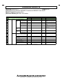
1.2.4 Functions
No. Item
QnUDVCPU
RCPU
Reference
1
2
3
4
SFC program
SFC program
Not supported
-
Structured ladder/FBD
Sampling trace function
Structured ladder/FBD
Sampling trace function
Not supported
Not supported
(a)
Latch data backup to standard
ROM
Latch data backup to standard ROM
Not supported
(b)
5
CPU module change function
with memory card
Monitor
CPU module change function with memory card
Not supported
(c)
Monitor condition setting
Not supported
(d)
Executional conditioned device test
Not supported
(e)
External input/output forced on/off function
Not supported
(f)
Execution time measurement
Scan time measurement
Not supported
(g)
MELSEC-A series compatible
function
Access by using A-compatible 1C/1E frame (A to Q
converted SM/SD areas (SM1000 to SM1255, SD1000 to
SD1255))
Not supported
(h)
11
High-speed interrupt function
High-speed interrupt (I49)
Interrupt using I49
(Use the High-speed I/O refresh function and the high-speed (Set an event execution type program which will be
buffer transfer function.)
triggered by the interrupt pointer I49, and perform refresh
for each program.)
(i)
12
13
14
Service processing
Data logging function
Service processing setting
Data logging file transfer function
Device/label access service processing setting
Not supported
(j)
(k)
Multiple CPU function
Access to the host CPU operation information area
(U3En\G0 and later) in CPU shared memory
Not supported
(l)
15
Multiple CPU high speed transmission area (U3En\G10000
and later) in the cyclic transmission area device
Fixed scan communication area (U3En\HG0 and later) in
the CPU buffer memory access device
(m)
16
Refresh using the multiple CPU high speed transmission
area (Data are refreshed during END processing.)
Refresh using the fixed scan communication area (Data are
refreshed at execution of the multiple CPU synchronous
interrupt program (I45).)
(n)
File password and remote
password
File password 32
(Length: 4 to 32 characters)
File password
(Length: 6 to 32 characters)
(o)
Self-diagnostics function
Remote password (Length: 4 characters)
Error clear
(Continuation errors can be cleared by types.)
Remote password (Length: 6 to 32 characters)
Error clear
(Continuation errors are batch-cleared.)
6
7
8
9
10
17
18
19
(p)
(a) Sampling trace function
The RCPU does not support the sampling trace function.
Use the trigger logging of the data logging function instead. Note that an SD memory card is required to store
data because the CPU built-in memory cannot be used as data storage destination in the RCPU.
(b) Latch data backup to standard ROM
The RCPU does not support the latch data backup to standard ROM function.
Use the data backup/restoration function of the GOT instead. Or, read data using GX Works3, store the data, and
write the data back again to the CPU module.
HEAD OFFICE : TOKYO BUILDING, 2-7-3 MARUNOUCHI, CHIYODA-KU, TOKYO 100-8310, JAPAN
NAGOYA WORKS : 1-14, YADA-MINAMI 5-CHOME, HIGASHI-KU, NAGOYA, JAPAN
TECHNICAL BULLETIN
[Issue No.] FA-A-0171
[Page] 18/62
[Title] Differences between MELSEC-Q series and MELSEC iQ-R series
[Date of Issue] November 2014
[Relevant Models] MELSEC iQ-R series
(c) CPU module change function with memory card
The RCPU does not support the CPU module change function with memory card.
Use the data backup/restoration function of the GOT instead. Or, read data using GX Works3, store the data, and
write the data back again to the CPU module.
(d) Monitor condition setting
The RCPU does not support the monitor condition setting.
Use the trigger logging of the data logging function instead.
Trigger logging collects monitor data at the timing of specified condition or step number.
(e) Executional conditioned device test
The RCPU does not support the executional conditioned device test.
To change a device value at the specified step, execute the online change function, and add a replacement
program to the desired position. (Delete the program to disable the processing.)
If the execution timing is set to before execution of an instruction in the QnUDVCPU program, add a program
for the device test before the corresponding step in the RCPU program. If the execution timing is set to after
execution of an instruction, add a program after the corresponding step.
Program and Device Test with Execution Condition window (GX Works2)
HEAD OFFICE : TOKYO BUILDING, 2-7-3 MARUNOUCHI, CHIYODA-KU, TOKYO 100-8310, JAPAN
NAGOYA WORKS : 1-14, YADA-MINAMI 5-CHOME, HIGASHI-KU, NAGOYA, JAPAN
TECHNICAL BULLETIN
[Issue No.] FA-A-0171
[Page] 19/62
[Title] Differences between MELSEC-Q series and MELSEC iQ-R series
[Date of Issue] November 2014
[Relevant Models] MELSEC iQ-R series
Program (GX Works3)
HEAD OFFICE : TOKYO BUILDING, 2-7-3 MARUNOUCHI, CHIYODA-KU, TOKYO 100-8310, JAPAN
NAGOYA WORKS : 1-14, YADA-MINAMI 5-CHOME, HIGASHI-KU, NAGOYA, JAPAN
TECHNICAL BULLETIN
[Issue No.] FA-A-0171
[Page] 20/62
[Title] Differences between MELSEC-Q series and MELSEC iQ-R series
[Date of Issue] November 2014
[Relevant Models] MELSEC iQ-R series
(f) External input/output forced on/off function
The RCPU does not support the external input/output forced on/off function.
Use the following program instead.
To forcibly turn on/off the X device, add the SET and RST instructions at the start of the scan program. To
forcibly turn on/off the Y device, add the SET and RST instructions at the end of the scan program.
<Forcibly turning on/off the X device>
<Forcibly turning on/off the Y device>
Forced Input Output
Registration/Cancellation
window (GX Works2)
Program (GX Works3)
<Restrictions>
The replacement program cannot be used in the following cases.
Input and output targeted for forced on/off are referred to or changed using the direct input device (DX) and
direct output device (DY).
Input and output targeted for forced on/off are referred to or changed within an interrupt program.
(g) Scan time measurement
The RCPU does not support the scan time measurement.
To check the scan time of programs being executed, use the program list monitor.
Refer to the instruction processing time list in the MELSEC iQ-R Programming Manual (Instructions, Standard
Functions/Function Blocks) to calculate the processing time of the specified program section.
(h) Access by using A-compatible 1C/1E frame (A to Q converted SM/SD areas (SM1000 to SM1255, SD1000 to
SD1255))
The RCPU does not support the access by using A-compatible 1C/1E frame. (The A to Q converted SM/SD
areas (SM1000 to SM1255, SD1000 to SD1255) cannot be used.) Use the QnA-compatible 3E/3C frame instead,
and access the SM/SD areas of the RCPU.
HEAD OFFICE : TOKYO BUILDING, 2-7-3 MARUNOUCHI, CHIYODA-KU, TOKYO 100-8310, JAPAN
NAGOYA WORKS : 1-14, YADA-MINAMI 5-CHOME, HIGASHI-KU, NAGOYA, JAPAN
TECHNICAL BULLETIN
[Issue No.] FA-A-0171
[Page] 21/62
[Title] Differences between MELSEC-Q series and MELSEC iQ-R series
[Date of Issue] November 2014
[Relevant Models] MELSEC iQ-R series
(i) High-speed interrupt function: high-speed I/O refresh function and high-speed transfer function
To perform the high-speed interrupt function with the RCPU, set an event execution type program which will be
triggered by the interrupt pointer I49 in CPU parameter (Program Setting) so that refresh is performed for each
program separately.
To perform high-speed I/O refresh or high-speed transfer, set refresh target data or refresh group in module
parameter of the target module.
PLC parameter setting window and program (GX Works2)
HEAD OFFICE : TOKYO BUILDING, 2-7-3 MARUNOUCHI, CHIYODA-KU, TOKYO 100-8310, JAPAN
NAGOYA WORKS : 1-14, YADA-MINAMI 5-CHOME, HIGASHI-KU, NAGOYA, JAPAN
TECHNICAL BULLETIN
[Issue No.] FA-A-0171
[Page] 22/62
[Title] Differences between MELSEC-Q series and MELSEC iQ-R series
[Date of Issue] November 2014
[Relevant Models] MELSEC iQ-R series
CPU parameter setting window, module parameter setting window, and program (GX Works3)
(j) Service processing
The RCPU performs file access processing, such as reading program files, without being synchronized with each
scan (not during END processing) so that the scan time will not be delayed due to the processing.
For this reason, the response performance does not improve even though the number of processing counts is
increased in the device/label access service processing setting. (The response performance does not improve
either even though the COM instruction is used.)
On the other hand, the RCPU performs device access processing, such as reading device data, during END
processing. Therefore, the response performance of device access processing can be improved by increasing the
number of processing counts in the device/label access service processing setting or by using the COM
instruction.
HEAD OFFICE : TOKYO BUILDING, 2-7-3 MARUNOUCHI, CHIYODA-KU, TOKYO 100-8310, JAPAN
NAGOYA WORKS : 1-14, YADA-MINAMI 5-CHOME, HIGASHI-KU, NAGOYA, JAPAN
TECHNICAL BULLETIN
[Issue No.] FA-A-0171
[Page] 23/62
[Title] Differences between MELSEC-Q series and MELSEC iQ-R series
[Date of Issue] November 2014
[Relevant Models] MELSEC iQ-R series
(k) Data logging file transfer function
The RCPU does not support the data logging file transfer function.
Use the FTP server function of built-in Ethernet and load logging result files in the CPU module to the server,
such as a personal computer.
File transfer window (CPU Module Logging Configuration Tool)
Command Prompt window for FTP file transfer
(l) Access to the host CPU operation information area in CPU shared memory
The RCPU does not have the host CPU operation information area (U3En/G0 and later) in CPU shared memory.
If the host CPU operation information area is used in the MELSEC-Q series program, the program needs to be
corrected.
To check the operation information of another CPU module, refresh the data in the corresponding special
register (SD) to the CPU shared memory, and then access to the data stored in the memory.
HEAD OFFICE : TOKYO BUILDING, 2-7-3 MARUNOUCHI, CHIYODA-KU, TOKYO 100-8310, JAPAN
NAGOYA WORKS : 1-14, YADA-MINAMI 5-CHOME, HIGASHI-KU, NAGOYA, JAPAN
TECHNICAL BULLETIN
[Issue No.] FA-A-0171
[Page] 24/62
[Title] Differences between MELSEC-Q series and MELSEC iQ-R series
[Date of Issue] November 2014
[Relevant Models] MELSEC iQ-R series
(m)Access to the multiple CPU high speed transmission area
Area used for data communications among multiple CPU modules has been extended in the RCPU. The multiple
CPU high speed transmission area is included in the fixed scan communication area, and the addresses have been
changed from U3En\G10000 and later to U3En\HG0 and later.
If the multiple CPU high speed transmission area is used in the MELSEC-Q series program, the program needs
to be corrected.
When the QnUDVCPU project created by using GX Works2 is opened and edited by using GX Works3, the
addresses U3En/G10000 and later are automatically converted to U3En/HG0 and later. Note, however, that if the
fixed scan communication area is accessed by using the FROM/TO instructions, the access method needs to be
corrected. Use the data transfer instruction and CPU buffer memory access device, (example: MOV U3En\HG*
D0) instead of the FROM/TO instructions.
Program that accesses to the multiple CPU high speed transmission area (GX Works2)
Program that accesses to the fixed scan communication area (GX Works3)
(n) Refresh using the multiple CPU high speed transmission area
The RCPU performs multiple CPU refresh at two timings: during END processing and at execution of the
multiple CPU synchronous interrupt (I45). Since refresh timing differs, if refresh using the multiple CPU high
speed transmission area is set in the MELSEC-Q series program, the program needs to be corrected.
To perform refresh during END processing, set the refresh timing in system parameter ("Refresh Setting (At the
END)" under "CPU Buffer Memory Setting").
PLC parameter setting window (Multiple CPU Setting) and refresh timing (GX Works2)
HEAD OFFICE : TOKYO BUILDING, 2-7-3 MARUNOUCHI, CHIYODA-KU, TOKYO 100-8310, JAPAN
NAGOYA WORKS : 1-14, YADA-MINAMI 5-CHOME, HIGASHI-KU, NAGOYA, JAPAN
TECHNICAL BULLETIN
[Issue No.] FA-A-0171
[Page] 25/62
[Title] Differences between MELSEC-Q series and MELSEC iQ-R series
[Date of Issue] November 2014
[Relevant Models] MELSEC iQ-R series
System parameter setting window (Multiple CPU Setting) and refresh timing (GX Works3)
(o) File password and remote password
The number of characters in a password differs between the QnUDVCPU and the RCPU. Set a password within
the range of 6 to 32 characters for the RCPU.
Also, change the password of an external device in accordance with the password set to the RCPU if there is any
external device, such as an FTP client, that accesses the programmable controller.
(p) Self-diagnostics function
The RCPU batch-clears all the continuation errors being detected.
The delete-target continuation error does not need to be specified individually.
The error code system for the RCPU has been renewed. If an error code is set as an operating condition or
interlock condition in the MELSEC-Q program, the program needs to be corrected.
HEAD OFFICE : TOKYO BUILDING, 2-7-3 MARUNOUCHI, CHIYODA-KU, TOKYO 100-8310, JAPAN
NAGOYA WORKS : 1-14, YADA-MINAMI 5-CHOME, HIGASHI-KU, NAGOYA, JAPAN
TECHNICAL BULLETIN
[Issue No.] FA-A-0171
[Page] 26/62
[Title] Differences between MELSEC-Q series and MELSEC iQ-R series
[Date of Issue] November 2014
[Relevant Models] MELSEC iQ-R series
1.3 Power supply modules, base units, I/O modules
This section describes the differences of power supply modules, base units, and I/O modules between MELSEC-Q
series and MELSEC iQ-R series.
1.3.1 Power supply modules
The following table summarizes the differences of power supply modules.
No.
Item
MELSEC-Q series
MELSEC iQ-R series
1
Terminal block screw size
M3.5
M4.0
1.3.2 Base units
The following table summarizes the differences of base units.
No.
Item
MELSEC-Q series
MELSEC iQ-R series
1
2
Extension level setting
Set with a connector pin.
Automatically recognized.
Extension cable connecting method
Fixing screw
Lock button
1.3.3 I/O modules
The following table summarizes the differences of I/O modules.
(1) Connector type
No.
Item
MELSEC-Q series (QX81, QY81P)
MELSEC iQ-R series (RX41C4, RY41PT1P)
1
Connector
37-pin D-sub connector
40-pin connector
(2) Interrupt function (interrupt module)
To use the interrupt function in the MELSEC iQ-R series system, use an input module. Set the interrupt function in
module parameter of the input module used.
(3) Parameters
No.
Item
MELSEC-Q series
MELSEC iQ-R series
1
2
3
Input response time
I/O assignment setting of PLC parameter
Module parameter
Interrupt setting
Error time output mode
HEAD OFFICE : TOKYO BUILDING, 2-7-3 MARUNOUCHI, CHIYODA-KU, TOKYO 100-8310, JAPAN
NAGOYA WORKS : 1-14, YADA-MINAMI 5-CHOME, HIGASHI-KU, NAGOYA, JAPAN
TECHNICAL BULLETIN
[Issue No.] FA-A-0171
[Page] 27/62
[Title] Differences between MELSEC-Q series and MELSEC iQ-R series
[Date of Issue] November 2014
[Relevant Models] MELSEC iQ-R series
1.4 Intelligent Function Modules
1.4.1 Analog-digital converter modules
This section describes the differences of analog-digital converter modules between MELSEC-Q series
(Q64AD/Q68ADV/Q68ADI) and MELSEC iQ-R series (R60AD4/R60ADV8/R60ADI8).
For details on the MELSEC iQ-R series modules, refer to the MELSEC iQ-R Analog-Digital Converter Module User's
Manual (Application) (SH-081233ENG).
(1) Dedicated instructions
There is no difference between MELSEC-Q series and MELSEC iQ-R series.
(2) Parameters
No.
MELSEC-Q series
1
Error time output mode
I/O assignment setting of PLC parameter
2
Switch setting
Intelligent function module parameter
3
Parameter (each setting)
4
Auto refresh
MELSEC iQ-R series
Module parameter
(3) I/O signals and buffer memory areas
The layouts of I/O signals and buffer memory areas differ between MELSEC-Q series and MELSEC iQ-R series.
If I/O signals and buffer memory areas are used in the MELSEC-Q series program, the program needs to be
corrected.
In Q compatible mode, the MELSEC-Q series program can be used as it is, except for the differences in the signals
and functions listed below.
No.
Signal name
MELSEC-Q series
MELSEC iQ-R series
1
X1
Temperature drift correction flag
Not supported
2
X8
High resolution mode status flag
Alert output signal
(4) Functions
No.
Item
MELSEC-Q series
MELSEC iQ-R series
Reference
1
Resolution mode switching function
Resolution mode switching function
Not supported
(a)
2
Temperature drift compensation function
Temperature drift compensation function
Not supported
(b)
(a) Resolution mode switching function
The MELSEC iQ-R series modules do not support the resolution mode switching function because the resolution
has already been enhanced.
Using the scaling function yields a value equivalent to that in the MELSEC-Q series. Note that the converted
value is stored into the "Digital operation value" area, and thus has a different buffer memory address to be
referred.
(b) Temperature drift compensation function
The MELSEC iQ-R series modules do not support the temperature drift compensation function because the
accuracy has already been enhanced. (The accuracy is comparable to that of the MELSEC-Q series with the
temperature drift compensation function used.) If the function is used in the MELSEC-Q series program, the
program needs to be corrected.
HEAD OFFICE : TOKYO BUILDING, 2-7-3 MARUNOUCHI, CHIYODA-KU, TOKYO 100-8310, JAPAN
NAGOYA WORKS : 1-14, YADA-MINAMI 5-CHOME, HIGASHI-KU, NAGOYA, JAPAN
TECHNICAL BULLETIN
[Issue No.] FA-A-0171
[Page] 28/62
[Title] Differences between MELSEC-Q series and MELSEC iQ-R series
[Date of Issue] November 2014
[Relevant Models] MELSEC iQ-R series
1.4.2 Digital-analog converter modules
This section describes the differences of digital-analog converter modules between MELSEC-Q series
(Q64DAN/Q68DAIN/Q68DAVN) and MELSEC iQ-R series (R60DA4/R60DAI8/R60DAV8).
For details on the MELSEC iQ-R series modules, refer to the MELSEC iQ-R Digital-Analog Converter Module User's
Manual (Application) (SH-081237ENG).
(1) Dedicated instructions
There is no difference between MELSEC-Q series and MELSEC iQ-R series.
(2) Parameters
No.
MELSEC-Q series
1
Error time output mode
I/O assignment setting of PLC parameter
2
3
Switch setting
Parameter (each setting)
Intelligent function module parameter
4
MELSEC iQ-R series
Module parameter
Auto refresh
(3) I/O signals and buffer memory areas
The layouts of I/O signals and buffer memory areas differ between MELSEC-Q series and MELSEC iQ-R series.
If I/O signals and buffer memory areas are used in the MELSEC-Q series program, the program needs to be
corrected.
In Q compatible mode, the MELSEC-Q series program can be used as it is, except for the differences in the signals
and functions listed below.
No.
Signal name
MELSEC-Q series
MELSEC iQ-R series
1
X8
High resolution mode status flag
Not supported
2
XD
Synchronous output mode flag
Disconnection detection signal
3
YD
Synchronous output request
Not supported
(4) Functions
No.
Item
MELSEC-Q series
MELSEC iQ-R series
Reference
1
Resolution mode switching function
Resolution mode switching function
Not supported
(a)
(a) Resolution mode switching function
The MELSEC iQ-R series modules do not support this function because the resolution has already been
enhanced.
Using the scaling function yields a value equivalent to that in the MELSEC-Q series. Note that the converted
value is stored into the "Digital operation value" area, and thus has a different buffer memory address to be
referred.
HEAD OFFICE : TOKYO BUILDING, 2-7-3 MARUNOUCHI, CHIYODA-KU, TOKYO 100-8310, JAPAN
NAGOYA WORKS : 1-14, YADA-MINAMI 5-CHOME, HIGASHI-KU, NAGOYA, JAPAN
TECHNICAL BULLETIN
[Issue No.] FA-A-0171
[Page] 29/62
[Title] Differences between MELSEC-Q series and MELSEC iQ-R series
[Date of Issue] November 2014
[Relevant Models] MELSEC iQ-R series
1.4.3 Simple motion modules
This section describes the differences of simple motion modules between MELSEC-Q series
(QD77MS2/QD77MS4/QD77MS16) and MELSEC iQ-R series (RD77MS2/RD77MS4/RD77MS8/RD77MS16).
For details on the MELSEC iQ-R series modules, refer to the MELSEC iQ-R Simple Motion Module User's Manual
(Application) (IB-0300247).
(1) Wiring
There is no difference between MELSEC-Q series and MELSEC iQ-R series.
(2) Program
(a) I/O signals
The layout of I/O signals differs between MELSEC-Q series and MELSEC iQ-R series.
If I/O signals are used in the MELSEC-Q series program, the program needs to be corrected.
The RD77MS16, however, allows the program to be used without correction.
(b) Buffer memory areas
The layout of buffer memory areas differs between MELSEC-Q series and MELSEC iQ-R series.
If buffer memory areas are used in the MELSEC-Q series program, the program needs to be corrected.
(c) Error codes and alarm codes
The error code system for the MELSEC iQ-R series has been renewed. If an error code is set as an operating
condition or interlock condition in the MELSEC-Q program, the program needs to be corrected.
HEAD OFFICE : TOKYO BUILDING, 2-7-3 MARUNOUCHI, CHIYODA-KU, TOKYO 100-8310, JAPAN
NAGOYA WORKS : 1-14, YADA-MINAMI 5-CHOME, HIGASHI-KU, NAGOYA, JAPAN
TECHNICAL BULLETIN
[Issue No.] FA-A-0171
[Page] 30/62
[Title] Differences between MELSEC-Q series and MELSEC iQ-R series
[Date of Issue] November 2014
[Relevant Models] MELSEC iQ-R series
1.4.4 Positioning modules
This section describes the differences of positioning modules between MELSEC-Q series
(QD75P2N/QD75P4N/QD75D2N/QD75D4N) and MELSEC iQ-R series (RD75P2/RD75P4/RD75D2/RD75D4).
For details on the MELSEC iQ-R series modules, refer to the MELSEC iQ-R Positioning Module User's Manual
(Application) (SH-081245ENG) and the MELSEC iQ-R Positioning Module User's Manual (Startup)
(SH-081243ENG).
(1) Wiring
There are differences in the layout of PULSE COM terminals between the QD75D2N/QD75D4N and the
RD75D2/RD75D4.
To use the 40-pin connector of the QD75D2N/QD75D4N with the RD75D2/RD75D4, wiring to the 2B20 and 2B19
pins is required.
(2) Dedicated instructions
There is no difference between MELSEC-Q series and MELSEC iQ-R series.
(3) Parameters
No.
MELSEC-Q series
1
Intelligent function module parameter
3
Error time output mode
Parameter (each setting)
Auto refresh
4
Positioning data
Intelligent function module parameter
5
Block start data
2
MELSEC iQ-R series
I/O assignment setting of PLC parameter
Module parameter
Module extension parameter
Writing parameters
The MELSEC iQ-R series allows parameters to be written to the CPU module as well as the positioning module.
This makes it possible to control parameters centrally by the CPU module, thereby making it easier to change the
module in maintenance.
The module parameters and module extension parameters stored in the CPU module are reflected to the
positioning module when the system is powered on, the CPU module is reset, or the operating status of the CPU
module is changed from STOP to RUN.
To set the module extension parameters using a program, execute the parameter setting program after Module
access flag turns on. Since the parameters stored in the CPU module is written to the positioning module when the
operating status of the CPU module is changed from STOP to RUN, execute the parameter setting program again.
To set positioning data using a program or change positioning data using the teaching function, especially for the
system where positioning data varies from one workpiece to another or the system where settings are changed
with GOT or other external devices, set "Positioning module" in "Extended parameter storage setting" under basic
setting of module parameter, and store parameters into the positioning module using the module backup function.
(4) I/O signals and buffer memory areas
The layouts of I/O signals and buffer memory areas differ between MELSEC-Q series and MELSEC iQ-R series.
If I/O signals and buffer memory areas are used in the MELSEC-Q series program, the program needs to be
corrected.
No.
Signal name
MELSEC-Q series
MELSEC iQ-R series
1
X1
Synchronization flag
Module access flag
(5) Functions
There is no difference between MELSEC-Q series and MELSEC iQ-R series.
HEAD OFFICE : TOKYO BUILDING, 2-7-3 MARUNOUCHI, CHIYODA-KU, TOKYO 100-8310, JAPAN
NAGOYA WORKS : 1-14, YADA-MINAMI 5-CHOME, HIGASHI-KU, NAGOYA, JAPAN
TECHNICAL BULLETIN
[Issue No.] FA-A-0171
[Page] 31/62
[Title] Differences between MELSEC-Q series and MELSEC iQ-R series
[Date of Issue] November 2014
[Relevant Models] MELSEC iQ-R series
1.4.5 High-speed counter modules
This section describes the differences of high-speed counter modules between MELSEC-Q series
(QD62/QD62D/QD62E) and MELSEC iQ-R series (RD62P2/RD62D2/RD62P2E).
For details on the MELSEC iQ-R series modules, refer to the MELSEC iQ-R High-Speed Counter Module User's
Manual (Application) (SH-081241ENG) and the MELSEC iQ-R High-Speed Counter Module User's Manual (Startup)
(SH-081239ENG).
(1) Wiring
The wiring for coincidence output differs between the QD62E and the RD62P2E.
To use the 40-pin connector of the QD62E with the RD62P2E, wiring to the A01 and A02 pins is no longer required.
(A01 and A02 are non-connection pins.)
(2) Dedicated instructions
There is no difference between MELSEC-Q series and MELSEC iQ-R series.
(3) Parameters
No.
MELSEC-Q series
1
2
3
Error time output mode
Switch setting
Parameter (each setting)
4
Auto refresh
MELSEC iQ-R series
I/O assignment setting of PLC parameter
Intelligent function module parameter
Module parameter
(4) I/O signals and buffer memory areas
The layouts of I/O signals and buffer memory areas differ between MELSEC-Q series and MELSEC iQ-R series.
If I/O signals and buffer memory areas are used in the MELSEC-Q series program, the program needs to be
corrected.
No.
Signal name
MELSEC-Q series
MELSEC iQ-R series
1
XF
Fuse blown detection flag
Not supported
(5) Functions
There is no difference between MELSEC-Q series and MELSEC iQ-R series.
HEAD OFFICE : TOKYO BUILDING, 2-7-3 MARUNOUCHI, CHIYODA-KU, TOKYO 100-8310, JAPAN
NAGOYA WORKS : 1-14, YADA-MINAMI 5-CHOME, HIGASHI-KU, NAGOYA, JAPAN
TECHNICAL BULLETIN
[Issue No.] FA-A-0171
[Page] 32/62
[Title] Differences between MELSEC-Q series and MELSEC iQ-R series
[Date of Issue] November 2014
[Relevant Models] MELSEC iQ-R series
1.5 Communication Modules and Network Modules
1.5.1 Common items for communication modules and network modules
(1) Parameter setting
Parameters must be set for each MELSEC iQ-R series communication modules and network modules.
Network parameter setting window (GX Works2)
Module parameter setting window (GX Works3)
HEAD OFFICE : TOKYO BUILDING, 2-7-3 MARUNOUCHI, CHIYODA-KU, TOKYO 100-8310, JAPAN
NAGOYA WORKS : 1-14, YADA-MINAMI 5-CHOME, HIGASHI-KU, NAGOYA, JAPAN
TECHNICAL BULLETIN
[Issue No.] FA-A-0171
[Page] 33/62
[Title] Differences between MELSEC-Q series and MELSEC iQ-R series
[Date of Issue] November 2014
[Relevant Models] MELSEC iQ-R series
(2) Interrupt setting
To execute an interrupt program in the MELSEC iQ-R series communication modules and network modules, set the
interrupt pointer number in module parameter.
Network parameter setting window (GX Works2)
Module parameter setting window (GX Works3)
(3) Dedicated instructions (common to Ethernet/CC-Link IE Field/CC-Link IE Controller)
The MELSEC iQ-R series modules cannot specify 254 (Network specified in Valid Module During Other Station
Access) as a network number in dedicated instructions. Specify the network number of the own station.
HEAD OFFICE : TOKYO BUILDING, 2-7-3 MARUNOUCHI, CHIYODA-KU, TOKYO 100-8310, JAPAN
NAGOYA WORKS : 1-14, YADA-MINAMI 5-CHOME, HIGASHI-KU, NAGOYA, JAPAN
TECHNICAL BULLETIN
[Issue No.] FA-A-0171
[Page] 34/62
[Title] Differences between MELSEC-Q series and MELSEC iQ-R series
[Date of Issue] November 2014
[Relevant Models] MELSEC iQ-R series
1.5.2 Ethernet interface modules
This section describes the differences of Ethernet interface modules between MELSEC-Q series (QJ71E71-100) and
MELSEC iQ-R series (RJ71EN71).
For details on the MELSEC iQ-R series module, refer to the MELSEC iQ-R Ethernet User's Manual (Application)
(SH-081257ENG).
(1) Dedicated instructions
No.
Classification
1
2
3
4
Ethernet
instruction
MELSEC-Q series
MELSEC iQ-R series
Opening a connection
ZP.OPEN
ZP.OPEN
Reference
(a)
Clearing error information
ZP.ERRCLR
ZP.ERRCLEAR
-
Reading received e-mail
ZP.MRECV
Not supported
-
Sending e-mail
ZP.MSEND
(a) ZP.OPEN
To perform open processing by using the control data, if the external device is specified with the MAC address,
change the MAC address to the IP address for the MELSEC iQ-R series module.
(2) Parameters
No.
Set in:
Item
MELSEC-Q series
Network parameter
MELSEC iQ-R series
Open setting
Module parameter
Reference
1
SLMP (MC protocol) communication setting
2
Random access buffer communication setting
(b)
(a)
3
Broadcast setting
(c)
4
Unused connection setting
(d)
5
TCP/IP connection module setting
(e)
6
Alive check setting
7
Online change setting
8
Send frame setting
(f)
Operation setting
(g)
(h)
9
Router relay (gateway) parameter setting
Router relay parameter
(i)
10
Interrupt setting
Interrupt setting
(j)
(a) SLMP (MC protocol) communication setting
Select "SLMP Connection Module" for the MELSEC iQ-R series module.
Network parameter setting window (GX Works2)
Module parameter setting window (GX Works3)
HEAD OFFICE : TOKYO BUILDING, 2-7-3 MARUNOUCHI, CHIYODA-KU, TOKYO 100-8310, JAPAN
NAGOYA WORKS : 1-14, YADA-MINAMI 5-CHOME, HIGASHI-KU, NAGOYA, JAPAN
TECHNICAL BULLETIN
[Issue No.] FA-A-0171
[Page] 35/62
[Title] Differences between MELSEC-Q series and MELSEC iQ-R series
[Date of Issue] November 2014
[Relevant Models] MELSEC iQ-R series
(b) Random access buffer communication setting
Select the connection target module, and then select "Random Access Buffer" in "Communication Method" for
the MELSEC iQ-R series module.
Network parameter setting window (GX Works2)
Module parameter setting window (GX Works3)
(c) Broadcast setting
Select the connection target module, and then select "Broadcast Send" or "Broadcast Receive" in
"Communication Method" for the MELSEC iQ-R series module.
Network parameter setting window (GX Works2)
Module parameter setting window (GX Works3)
HEAD OFFICE : TOKYO BUILDING, 2-7-3 MARUNOUCHI, CHIYODA-KU, TOKYO 100-8310, JAPAN
NAGOYA WORKS : 1-14, YADA-MINAMI 5-CHOME, HIGASHI-KU, NAGOYA, JAPAN
TECHNICAL BULLETIN
[Issue No.] FA-A-0171
[Page] 36/62
[Title] Differences between MELSEC-Q series and MELSEC iQ-R series
[Date of Issue] November 2014
[Relevant Models] MELSEC iQ-R series
(d) Unused connection setting
Set "MELSOFT Connection Module" to the connection number not used for the MELSEC iQ-R series module.
Network parameter setting window (GX Works2)
Module parameter setting window (GX Works3)
(e) TCP/IP connection module setting
Setting the connected device automatically determines the protocol in the MELSEC iQ-R series module.
Network parameter setting window (GX Works2)
Module parameter setting window (GX Works3)
HEAD OFFICE : TOKYO BUILDING, 2-7-3 MARUNOUCHI, CHIYODA-KU, TOKYO 100-8310, JAPAN
NAGOYA WORKS : 1-14, YADA-MINAMI 5-CHOME, HIGASHI-KU, NAGOYA, JAPAN
TECHNICAL BULLETIN
[Issue No.] FA-A-0171
[Page] 37/62
[Title] Differences between MELSEC-Q series and MELSEC iQ-R series
[Date of Issue] November 2014
[Relevant Models] MELSEC iQ-R series
(f) Alive check ("Existence Confirmation") setting
For the MELSEC iQ-R series module, set whether to perform an alive check in "External Device Configuration"
for each connection. For the TCP/IP alive check, only the KeepAlive command can be used.
Network parameter setting window (GX Works2)
Module parameter setting window (GX Works3)
HEAD OFFICE : TOKYO BUILDING, 2-7-3 MARUNOUCHI, CHIYODA-KU, TOKYO 100-8310, JAPAN
NAGOYA WORKS : 1-14, YADA-MINAMI 5-CHOME, HIGASHI-KU, NAGOYA, JAPAN
TECHNICAL BULLETIN
[Issue No.] FA-A-0171
[Page] 38/62
[Title] Differences between MELSEC-Q series and MELSEC iQ-R series
[Date of Issue] November 2014
[Relevant Models] MELSEC iQ-R series
(g) Online change setting
For the MELSEC iQ-R series module, enable the online change function in "Enable/Disable Online Change"
under "Own Node Settings" of "Basic Settings" when the SLMP communications are performed. When the FTP
server function is used, enable the function in "Allow Online Change" under "FTP Server Settings" of
"Application Settings".
Module parameter setting window (GX Works2)
Module parameter setting window (GX Works3)
(h) Send frame setting
Only "Ethernet (V2.0)" frame can be used for the MELSEC iQ-R series module. "IEEE802.3" frame can be used
for send data only.
HEAD OFFICE : TOKYO BUILDING, 2-7-3 MARUNOUCHI, CHIYODA-KU, TOKYO 100-8310, JAPAN
NAGOYA WORKS : 1-14, YADA-MINAMI 5-CHOME, HIGASHI-KU, NAGOYA, JAPAN
TECHNICAL BULLETIN
[Issue No.] FA-A-0171
[Page] 39/62
[Title] Differences between MELSEC-Q series and MELSEC iQ-R series
[Date of Issue] November 2014
[Relevant Models] MELSEC iQ-R series
(i) Gateway parameter setting (router relay parameter)
Set "Subnet Mask" or "Default Gateway" under "Own Node Settings" of "Basic Settings" and set "Gateway
Information" under "Gateway Parameter Settings" of "Application Settings" for the MELSEC iQ-R series
module.
Names of some parameter setting items have been changed for the MELSEC iQ-R series module.
"Subnet Mask Pattern" → "Subnet Mask"
"Default Router IP Address" → "Default Gateway"
"Router Information" → "Gateway Information"
"Router IP Address" → "Gateway IP Address"
Network parameter setting window (GX Works2)
Module parameter setting window (GX Works3)
(j) Interrupt setting
Names of some parameter setting items have been changed for the MELSEC iQ-R series module.
"RECVS Instruction" → "SEND Instruction Data Reception"
"Fixed Buffer" → "Reception Connection"
HEAD OFFICE : TOKYO BUILDING, 2-7-3 MARUNOUCHI, CHIYODA-KU, TOKYO 100-8310, JAPAN
NAGOYA WORKS : 1-14, YADA-MINAMI 5-CHOME, HIGASHI-KU, NAGOYA, JAPAN
TECHNICAL BULLETIN
[Issue No.] FA-A-0171
[Page] 40/62
[Title] Differences between MELSEC-Q series and MELSEC iQ-R series
[Date of Issue] November 2014
[Relevant Models] MELSEC iQ-R series
(3) I/O signals and buffer memory areas
The layouts of I/O signals and buffer memory areas differ between MELSEC-Q series and MELSEC iQ-R series.
If I/O signals and buffer memory areas are used in the MELSEC-Q series program, the program needs to be
corrected.
(4) Functions
No.
Item
MELSEC-Q series
MELSEC iQ-R series
Reference
1
2
3
E-mail function
E-mail function
Not supported
-
Web function
SLMP (MC protocol)
Web function
A-compatible 1E frame
Not supported
Not supported
-
HEAD OFFICE : TOKYO BUILDING, 2-7-3 MARUNOUCHI, CHIYODA-KU, TOKYO 100-8310, JAPAN
NAGOYA WORKS : 1-14, YADA-MINAMI 5-CHOME, HIGASHI-KU, NAGOYA, JAPAN
TECHNICAL BULLETIN
[Issue No.] FA-A-0171
[Page] 41/62
[Title] Differences between MELSEC-Q series and MELSEC iQ-R series
[Date of Issue] November 2014
[Relevant Models] MELSEC iQ-R series
1.5.3 CC-Link IE Field Network master/local modules
This section describes the differences of CC-Link IE Field Network modules between MELSEC-Q series
(QJ71GF11-T2) and MELSEC iQ-R series (RJ71GF11-T2 (RJ71EN71*1)).
For details on the MELSEC iQ-R series module, refer to the MELSEC iQ-R CC-Link IE Field Network User's Manual
(Application) (SH-081259ENG).
*1 The RJ71EN71 can be used as a CC-Link IE Field Network module or Ethernet module by switching the mode in parameter. Unless otherwise
specified, the RJ71EN71 set to be used as a CC-Link IE Field Network module in parameter is called the RJ71GF11-T2 in this bulletin.
(1) System configuration
When the module other than the RJ71GF11-T2 is used as the master station, there may be additional restrictions to
the serial number of the master station used.
Use any of the following modules as the master station.
Serial number (first five digits)*2
Model
QJ71GF11-T2
16012 or later
LJ71GF11-T2
16012 or later
Q81BD-J71GF11-T2
16012 or later
QS0J71GF11-T2
16022 or later
*2 If the serial number (first five digits) of the master station is earlier than the number described above, set "RX/RY Setting" in "Network
Configuration Settings" of the master station to the following.
Action
Example
Set the largest end number in
all stations to multiples of 32
minus 1 by changing the
number of cyclic assignment
points or adding a reserved
station.
Before change
After change
Set the largest end number in
all stations to 7FH or less.
Before change
After change
(2) Dedicated instructions
There is no difference between MELSEC-Q series and MELSEC iQ-R series.
HEAD OFFICE : TOKYO BUILDING, 2-7-3 MARUNOUCHI, CHIYODA-KU, TOKYO 100-8310, JAPAN
NAGOYA WORKS : 1-14, YADA-MINAMI 5-CHOME, HIGASHI-KU, NAGOYA, JAPAN
TECHNICAL BULLETIN
[Issue No.] FA-A-0171
[Page] 42/62
[Title] Differences between MELSEC-Q series and MELSEC iQ-R series
[Date of Issue] November 2014
[Relevant Models] MELSEC iQ-R series
(3) Parameters
No.
MELSEC-Q series
1
Network parameter
2
MELSEC iQ-R series
Network configuration setting
Module parameter
Mode
Reference
Basic setting
Application setting
Network
configuration setting
Module operation
mode setting
(a)
(b)
(a) Network configuration setting
For the MELSEC-Q series module, the configuration setting can be set in table format and CC IE Field
configuration window. However, for the MELSEC iQ-R series module, the configuration setting can be set only
in the CC IE Field configuration window.
(b) Module operation mode setting
For the MELSEC iQ-R series module, the hardware test and self-loopback test are integrated into the module
communication test.
The loop test cannot be used. Check the network status in the CC-Link IE Field Network diagnostics window of
GX Works3.
No.
Item
MELSEC-Q series
1
Hardware test
Hardware test
2
Self-loopback test
Self-loopback test
3
Loop test
Loop test
MELSEC iQ-R series
Module communication test
Not supported
(4) Link special relay (SB) and link special register (SW)
The SB/SW number assignment differs between the MELSEC-Q series and MELSEC iQ-R series modules. If
SB/SW is used in the MELSEC-Q series program, the program needs to be corrected.
Item
MELSEC-Q series
MELSEC iQ-R series
Event history clear acceptance status/completion status
Event history status
SB0061, SB0062
SB007A
N/A
N/A
Event count
Hardware test completion status
SW007A
SB0090, SB0091
N/A
N/A
Self-loopback test completion status, normal/abnormal end
Loop test completion status, normal/abnormal end
SB0092, SB0093
SB0094, SB0095
N/A
N/A
Loop test request accept status
Loop test result
SB009A
SW0194
N/A
N/A
Loop test error station
SW01A0 to SW01A7
N/A
(5) Functions
There is no difference between MELSEC-Q series and MELSEC iQ-R series.
HEAD OFFICE : TOKYO BUILDING, 2-7-3 MARUNOUCHI, CHIYODA-KU, TOKYO 100-8310, JAPAN
NAGOYA WORKS : 1-14, YADA-MINAMI 5-CHOME, HIGASHI-KU, NAGOYA, JAPAN
TECHNICAL BULLETIN
[Issue No.] FA-A-0171
[Page] 43/62
[Title] Differences between MELSEC-Q series and MELSEC iQ-R series
[Date of Issue] November 2014
[Relevant Models] MELSEC iQ-R series
1.5.4 CC-Link system master/local modules
This section describes the differences of CC-Link system master/local modules between MELSEC-Q series
(QJ61BT11N) and MELSEC iQ-R series (RJ61BT11).
For details on the MELSEC iQ-R series module, refer to the MELSEC iQ-R CC-Link System Master/Local Module
User's Manual (Application) (SH-081270ENG).
(1) Dedicated instructions
No.
Classification
MELSEC-Q series
MELSEC iQ-R series
Reference
1
Setting network parameters of the master
station
RLPASET
RLPASET
(a)
(a) RLPASET
For the MELSEC-Q series module, the mode is set in b14 and b15 of the device (S1+1) (Setting flag) in the
control data. However, for the MELSEC iQ-R series, set 0 in b14 and b15 because the mode is set in module
parameter.
Setting data of the QJ61BT11N
Setting data of the RJ61BT11N
(2) Parameters
No.
Item
MELSEC-Q series
MELSEC iQ-R series
Reference
1
Set with the rotary switch.
Set in module parameters.
-
2
Station number setting/transmission
speed
Mode setting
Set in network parameter or switch
setting.
Set in module parameters.
-
3
Refresh
Set the start number of the refresh target
device.
Set the start number and end number, or the
start number and number of points of the
refresh target device.
-
4
CC-Link configuration setting
Set in the station information settings
(table format) or CC-Link configuration
setting.
Set in the CC-Link configuration setting.
-
(3) Link special relay (SB) and link special register (SW)
The SB/SW number assignment differs between the MELSEC-Q series and MELSEC iQ-R series modules. Also,
some SB/SW areas are used for different purposes. If SB/SW is used in the MELSEC-Q series program, the
program needs to be corrected.
Item
MELSEC-Q series
MELSEC iQ-R series
Switch setting status
Own station switch change detection
SB006A
SB0078
N/A
N/A
Automatic CC-Link startup execution result
Switch setting status
SW0052
SW006A
N/A
N/A
Remote device station initialization procedure
registration execution individual information
SW0110 to SW011F
Un\G23680 to Un\G23743
HEAD OFFICE : TOKYO BUILDING, 2-7-3 MARUNOUCHI, CHIYODA-KU, TOKYO 100-8310, JAPAN
NAGOYA WORKS : 1-14, YADA-MINAMI 5-CHOME, HIGASHI-KU, NAGOYA, JAPAN
TECHNICAL BULLETIN
[Issue No.] FA-A-0171
[Page] 44/62
[Title] Differences between MELSEC-Q series and MELSEC iQ-R series
[Date of Issue] November 2014
[Relevant Models] MELSEC iQ-R series
(4) Buffer memory areas
The layout of buffer memory areas differs between MELSEC-Q series and MELSEC iQ-R series.
If buffer memory areas are used in the MELSEC-Q series program, the program needs to be corrected.
(5) Functions
No.
Item
MELSEC-Q series
MELSEC iQ-R series
Reference
1
2
Mode setting
Remote net additional mode
Not supported
-
Automatic CC-Link startup function
Automatic CC-Link startup
Not supported
-
1.5.5 Serial communication modules
This section describes the differences of serial communication modules between MELSEC-Q series
(QJ71C24N/QJ71C24N-R2/QJ71C24N-R4) and MELSEC iQ-R series (RJ71C24/RJ71C24-R2/RJ71C24-R4).
For details on the MELSEC iQ-R series modules, refer to the MELSEC iQ-R Serial Communication Module User's
Manual (Application) (SH-081251ENG).
(1) Dedicated instructions
There is no difference between MELSEC-Q series and MELSEC iQ-R series.
(2) Parameters
No.
MELSEC-Q series
1
Switch setting
I/O assignment setting of PLC parameter
2
Various control specification
Intelligent function module parameter
3
Programmable controller CPU monitoring
function
4
User frame specification
5
Auto refresh
6
Modem function
7
User frame content
MELSEC iQ-R series
Module parameter
Module extension parameter*1
*1 Pager receiver specification of data for modem connection registration and refresh settings for confirmation of notification status cannot be used.
Writing parameters
The MELSEC iQ-R series allows parameters to be written to the CPU module as well as the serial communication
module. This makes it possible to control parameters centrally by the CPU module, thereby making it easier to change
the module in maintenance.
The module parameters and module extension parameters stored in the CPU module are reflected to the serial
communication module when the system is powered on, the CPU module is reset, or the operating status of the CPU
module is changed from STOP to RUN.
(3) I/O signals
The layout of I/O signals differs between MELSEC-Q series and MELSEC iQ-R series.
If I/O signals are used in the MELSEC-Q series program, the program needs to be corrected.
No.
Signal name
MELSEC-Q series
MELSEC iQ-R series
1
X15
Notification normal completion
Not supported
2
3
X16
X19
Notification abnormal completion
Flash ROM system setting write completion
Not supported
Not supported
4
YE
CH1 ERR. clear request
ERR. clear request
5
YF
CH2 ERR. clear request
Not supported
6
Y14
Notification-issued request
Not supported
7
Y19
Flash ROM system request
Not supported
HEAD OFFICE : TOKYO BUILDING, 2-7-3 MARUNOUCHI, CHIYODA-KU, TOKYO 100-8310, JAPAN
NAGOYA WORKS : 1-14, YADA-MINAMI 5-CHOME, HIGASHI-KU, NAGOYA, JAPAN
TECHNICAL BULLETIN
[Issue No.] FA-A-0171
[Page] 45/62
[Title] Differences between MELSEC-Q series and MELSEC iQ-R series
[Date of Issue] November 2014
[Relevant Models] MELSEC iQ-R series
(4) Buffer memory areas
The layout of buffer memory areas differs between MELSEC-Q series and MELSEC iQ-R series.
If buffer memory areas are used in the MELSEC-Q series program, the program needs to be corrected.
(5) Functions
There is no difference between MELSEC-Q series and MELSEC iQ-R series.
HEAD OFFICE : TOKYO BUILDING, 2-7-3 MARUNOUCHI, CHIYODA-KU, TOKYO 100-8310, JAPAN
NAGOYA WORKS : 1-14, YADA-MINAMI 5-CHOME, HIGASHI-KU, NAGOYA, JAPAN
TECHNICAL BULLETIN
[Issue No.] FA-A-0171
[Page] 46/62
[Title] Differences between MELSEC-Q series and MELSEC iQ-R series
[Date of Issue] November 2014
[Relevant Models] MELSEC iQ-R series
2 SPECIFICATIONS DIFFERENCES BETWEEN MELSEC-Q SERIES AND MELSEC iQ-R SERIES
2.1 CPU Modules (QnUDVCPU and RCPU)
No.
Item
Number of mountable modules
1 System
Ethernet module
2 configuration
CC-Link IE Controller Network
3
module
CC-Link IE Field Network module
4
5
6
7
8
9
10
11
12
Number of
mountable
modules (Q
series)
Mountable
module
QnUDVCPU
Availability
Remarks
○
64 maximum
○
4 maximum
○
4 maximum
○
CC-Link module
○
MELSECNET/H module
○
Interrupt module (no setting by the
engineering tool)
○
MELSEC iQ-R series module
MELSEC-Q series module
MELSEC-AnS/A series module
Bus-connection of GOT
Extension level
×
○
○
○
○
Extension cable length
13
14 Programming Programming Ladder diagram (LD)
15
language
Sequential function chart (SFC)
16
Structured text (ST)
17
Function block diagram
(FBD)/Structured ladder
18
Function block (FB)
Program
Initial execution type
19
execution
20
Scan execution type
type
21
Fixed scan execution type
22
Standby type
Event execution type
23
Number of I/O points
24
[point]
25
User device
File register
26
○
○
○
○
○
27
System device
○
28
Constant scan
29
Fixed scan
interrupt
30
31 Memory
32 capacity
33
34
35 Processing
time
36
37
38
○
○
○
○
○
×
○
○
○
1 maximum/4 maximum (in a
multiple CPU system)
Some modules have restrictions.
7 maximum (Set the level with a
connector pin.)
13.2m maximum
○
1 maximum/4 maximum (in a
multiple CPU system)
○
○
×
×
○
Some modules have restrictions.
○
○
×
○
×
○
○
○
○
○
○
○
○
○
(Connect the GOT over Ethernet.)
7 maximum (The level is
automatically recognized.)
20m maximum
○
0.5 to 2000 (in increments of
0.1ms)
0.5 to 1000 (in increments of
0.5ms)
0.1 to 1.0 (in increments of 0.1ms)
○
[step]
[byte]
[byte]
○
○
○
30K/40K/60K/130K/260K
120K/160K/240K/520K/1040K
192K/256K/768K/1024K/1280K
○
○
○
Newly added.
4096
The device assignment differs.
Extended data register (D) and
extended link register (W) are not
provided.
The SM/SD number assignment
differs.
0.2 to 2000 (in increments of
0.1ms)
0.5 to 1000 (in increments of
0.5ms)
0.05 to 1000 (in increments of
0.05ms)
40K/80K/160K/320K/1200K
160K/320K/640K/1280K/4800K
400K/1188K/1720K/2316K/3380K
[byte]
○
○
2M/5M/10M/20M/40M
[ns]
○
1025.5K/1025.5K/1025.5K/2051K/
4102K
1.9
○
0.98
[ns]
○
3.9
○
1.96
[ns]
○
3.9
○
1.96
[Instruction/μs]
○
220
○
419
[ms]
○
I28 to I31
[ms]
○
I49
[ms]
Program capacity
Program memory
Standard RAM,
device/label memory
Standard ROM,
data memory
Processing
LD
time
instruction
OUT
instruction
MOV
instruction
PC MIX value
8 maximum/32 maximum (in a
multiple CPU system)
8 maximum/32 maximum (in a
multiple CPU system)
4 maximum
RnCPU
Availability
Remarks
○
64 maximum
○
No restrictions
○
8 maximum/32 maximum (in a
multiple CPU system)
○
8 maximum/32 maximum (in a
multiple CPU system)
○
8 maximum/32 maximum (in a
multiple CPU system)
×
4096
○
○
○
HEAD OFFICE : TOKYO BUILDING, 2-7-3 MARUNOUCHI, CHIYODA-KU, TOKYO 100-8310, JAPAN
NAGOYA WORKS : 1-14, YADA-MINAMI 5-CHOME, HIGASHI-KU, NAGOYA, JAPAN
TECHNICAL BULLETIN
[Issue No.] FA-A-0171
[Page] 47/62
[Title] Differences between MELSEC-Q series and MELSEC iQ-R series
[Date of Issue] November 2014
[Relevant Models] MELSEC iQ-R series
No.
39 Instruction
40
41
42
43
44
45
46
47
48
49
50
51
52
Item
Sequence instruction
Basic instruction
Converting 16-bit binary data to 32bit floating point type real number
Converting 32-bit binary data to 32bit floating point type real number
Converting 16-bit binary data to 64bit floating point type real number
Converting 32-bit binary data to 64bit floating point type real number
Converting 32-bit floating point type
real number to 16-bit binary data
Converting 32-bit floating point type
real number to 32-bit binary data
Converting 64-bit floating point type
real number to 16-bit binary data
Converting 64-bit floating point type
real number to 32-bit binary data
Converting 16-bit binary data to 32bit binary data
Converting 32-bit binary data to 16bit binary data
Converting 32-bit floating point type
real number to 64-bit floating point
type real number
Converting 64-bit floating point type
real number to 32-bit floating point
type real number
QnUDVCPU
Availability
Remarks
○
○
○
FLT
RnCPU
Availability
Remarks
○
○
○
INT2FLT
○
DFLT
○
DINT2FLT
○
FLTD
○
INT2DBL
○
DFLTD
○
DINT2DBL
○
INT
○
FLT2INT
○
DINT
○
FLT2DINT
○
INTD
○
DBL2INT
○
DINTD
○
DBL2DINT
○
DBL
○
INT2DINT
○
WORD
○
DINT2INT
○
ECON
○
FLT2DBL
○
EDCON
○
DBL2FLT
HEAD OFFICE : TOKYO BUILDING, 2-7-3 MARUNOUCHI, CHIYODA-KU, TOKYO 100-8310, JAPAN
NAGOYA WORKS : 1-14, YADA-MINAMI 5-CHOME, HIGASHI-KU, NAGOYA, JAPAN
TECHNICAL BULLETIN
[Issue No.] FA-A-0171
[Page] 48/62
[Title] Differences between MELSEC-Q series and MELSEC iQ-R series
[Date of Issue] November 2014
[Relevant Models] MELSEC iQ-R series
No.
53 Instruction
54
55
56
57
58
59
60
QnUDVCPU
Availability
Remarks
Application instruction
○
Converting hexadecimal ASCII code
○
HEX
to 16-bit binary data
○
ASC
Converting 16-bit binary data to
hexadecimal ASCII code
○
SQR
Calculating the square root of
floating-point data (single precision)
○
SQRD
Calculating the square root of
floating-point data (double
precision)
○
BSQR
Calculating the square root of BCD 4digit
○
BDSQR
Calculating the square root of BCD 8digit
○
RAMP
Ramp signal instruction
Item
RnCPU
Availability
Remarks
○
○
ASC2INT
○
INT2ASC
○
ESQRT
○
EDSQRT
○
BSQRT
○
BDSQRT
○
RAMPQ
61
Searching 16-bit binary data
○
SER
○
SERDATA
62
Searching 32-bit binary data
○
DSER
○
DSERDATA
63
Sorting 16-bit binary data
○
SORT
○
SORTD
64
Sorting 32-bit binary data
○
DSORT
○
DSORTD
65
Converting time data from
hour/minute/second to second
Converting time data from second to
hour/minute/second
Reading 32-bit binary data (buffer
memory access)
Disabling interrupt programs
Enabling interrupt programs
Selecting refresh to be performed
○
SECOND
○
TIME2SEC
○
HOUR
○
SEC2TIME
○
DFRO
○
DFROM
○
○
○
DI (without execution condition)
EI (without execution condition)
COM (without execution condition)
○
○
○
DI (with execution condition)
EI (with execution condition)
COM (with execution condition)
○
CCOM
○
COM
○
○
○
COMRD
QCDSET
RBMOV
×
×
×
Use the BMOV instruction instead.
○
TO/S.TO
○
TO
○
UNIRD
○
UNIINFRD
66
67
68
69
70
71
72
73
74
75
76
Selecting refresh to be performed
(with execution condition)
Reading device comment
Setting a comment file name
High-speed block transfer of file
register
Writing data to host CPU shared
memory
Reading module information
HEAD OFFICE : TOKYO BUILDING, 2-7-3 MARUNOUCHI, CHIYODA-KU, TOKYO 100-8310, JAPAN
NAGOYA WORKS : 1-14, YADA-MINAMI 5-CHOME, HIGASHI-KU, NAGOYA, JAPAN
TECHNICAL BULLETIN
[Issue No.] FA-A-0171
[Page] 49/62
[Title] Differences between MELSEC-Q series and MELSEC iQ-R series
[Date of Issue] November 2014
[Relevant Models] MELSEC iQ-R series
No.
Item
77 Function
Clock function
78
79
80
LED indication
Scan monitoring function (WDT setting)
Interrupt function
81
82
83
84
85
86
87
88
High-speed interrupt (I49)
Database function
Device
Local device
×
○
○
○
○
×
○
○
○
○
×
○
○
Device initial value
Label
Local label
Label initial value (global
label/local label)
Label access setting from external
device
89
○
○
○
×
RnCPU
Availability
Remarks
○
The time zone setting has been
added.
○
○
○
The multiple interrupt function has
been added.
The high-speed I/O refresh function
○
The high-speed I/O refresh function
and high-speed transfer function are
and high-speed transfer function are
supported.
not supported.
○
Newly added.
○
○
Local devices should be described
with "#".
○
○
○
○
Newly added.
Availability
○
QnUDVCPU
Remarks
90
91
Latch function
92
93
94
Boot operation
Service processing setting
Access by using A-compatible 1C/1E frame
(SM/SD areas after A to Q conversion (SM1000 to
SM1255, SD1000 to SD1255))
Multiple CPU I/O sharing when using multiple
function
CPUs
Error time output mode
Multiple CPU synchronized startup
Multiple CPU clock synchronization
Communications by refresh
○
○
○
○
○
×
○
○
○
○
○
○
○
○
○
○
100
Access to CPU shared memory/CPU
buffer memory
○
101
High-speed
transmission
between
CPUs/fixed
scan
transmission
95
96
97
98
99
Latch data backup to standard ROM
Data are refreshed during END
processing.
FROM/TO instructions, cyclic
transmission area device (U3En/G0
and later)
0.88 (fixed)
○
Multiple CPU
synchronous interrupt
(I45) [ms]
Communications by
refresh
Area access method
○
104
105
Multiple CPU dedicated instruction
Sampling trace
○
○
○
×
106
Data logging Trigger logging and continuous
logging
function
Saving format of the data logging file
○
○
File transfer function
Scan time measurement
Diagnostics Self-diagnostics function
function
Error clear
○
○
○
102
103
107
108
109
110
111
○
○
○
○
Data are refreshed during END
processing.
FROM/TO instructions, cyclic
transmission area device
(U3En/G1000 and later)
CSV format
○
○
○
○
×
×
○
Continuation errors can be cleared
by types.
○
HEAD OFFICE : TOKYO BUILDING, 2-7-3 MARUNOUCHI, CHIYODA-KU, TOKYO 100-8310, JAPAN
NAGOYA WORKS : 1-14, YADA-MINAMI 5-CHOME, HIGASHI-KU, NAGOYA, JAPAN
Newly added.
Use the data backup/restoration
function of a GOT.
Data are refreshed during END
processing.
FROM/TO instructions, CPU buffer
memory access device (U3En/G0
and later)
0.10 to 10.00 (variable)
Data are refreshed at execution of
the interrupt pointer, I45.
CPU buffer memory access device
(U3En/HG0 and later)
Use the trigger logging of the data
logging function.
Unicode text file format, binary file
format
The error code system has been
changed.
Continuation errors are batchcleared.
TECHNICAL BULLETIN
[Issue No.] FA-A-0171
[Page] 50/62
[Title] Differences between MELSEC-Q series and MELSEC iQ-R series
[Date of Issue] November 2014
[Relevant Models] MELSEC iQ-R series
No.
112 Function
113
114
115
Item
History
function
Monitor
function
Error history
Monitor
Monitor condition setting
External input/output forced on/off
function
Executional conditioned device test
Online change (ladder mode)
Online change (files)
Change TC setting value
116
117
118
119
Online
change
120
CPU module change function with memory card
121
122
123
Security
124
125
126
127
128
129
Built-in
Ethernet
function
File password (file password 32)
Remote password
Connection with MELSOFT
products and GOT
Communications using MC
protocol/SLMP
Socket communications
Communications using the
predefined protocol
Time setting function (SNTP client)
File transfer function (FTP server)
IP address change function
Availability
○
QnUDVCPU
Remarks
○
○
○
RnCPU
Availability
Remarks
○
The event history function has been
added.
○
×
×
○
○
○
○
×
○
○
×
○
×
○
○
○
4 to 32 characters (variable)
4 characters (fixed)
○
○
○
○
○
○
○
○
○
○
○
○
○
○
○
Use the watch function of GX
Works3.
Use the data backup/restoration
function of a GOT.
6 to 32 characters (variable)
6 to 32 characters (variable)
2.2 Power Supply Modules, Base Units, I/O Modules
No.
Item
1 Power supply
2 module
3 Base unit
4
5
Rated output current
Terminal block screw size
Extension cable connecting method
Extension level setting
DIN rail adapter
6 I/O module
Input module Input response time setting
7
8
9
10
OFF
32-point/64-point type
voltage/OFF
current
Response
Set value: 0.1
time
ON→OFF Set value: 0.2
maximum
Interrupt function
I/O combined OFF voltage/OFF current
module
-
MELSEC-Q series
MELSEC iQ-R series
Remarks
Availability
Remarks
6.0A
6.5A
M3.5
M4.0
Fixing screw
Lock button
Set with a connector pin.
×
Automatically recognized.
MELSEC-Q series DIN rail adapter
MELSEC iQ-R series DIN rail
adapter
○
Supported (The time value can be
Supported (The set value applies to
set to each point.)
all points.)
11V or lower/1.7mA or lower
6V or lower/1mA or lower
○
QX40-S1: 0.20ms
○
0.35ms
○
QX40-S1: 0.30ms
○
0.40ms
○
QI60 (All points are set as interrupt
pointers.)
11V or lower/1.7mA or lower
○
Input module (An interrupt pointer
can be set to the specified point.)
6V or lower/1mA or lower
Availability
○
○
-
-
HEAD OFFICE : TOKYO BUILDING, 2-7-3 MARUNOUCHI, CHIYODA-KU, TOKYO 100-8310, JAPAN
NAGOYA WORKS : 1-14, YADA-MINAMI 5-CHOME, HIGASHI-KU, NAGOYA, JAPAN
TECHNICAL BULLETIN
[Issue No.] FA-A-0171
[Page] 51/62
[Title] Differences between MELSEC-Q series and MELSEC iQ-R series
[Date of Issue] November 2014
[Relevant Models] MELSEC iQ-R series
2.3 Intelligent Function Modules
2.3.1 Analog-digital converter modules
No.
Item
1 Performance Digital output (resolution)
specifications
2
Accuracy (accuracy for the maximum
digital output value)
3 Function
Analog input range
4
Temperature drift compensation
5
I/O signals
6
A/D conversion method
7
8
9
10
11
12
13
14
15
16
17
18
Scaling function
Shift function
Digital clipping function
Difference conversion function
Alert output function (process alarm)
Alert output function (rate alarm)
Input signal error detection function
Logging function
Inter-module synchronization function
Error history function
Event history function
Interrupt function
Q64AD, Q68ADV, Q68ADI
R60AD4, R60ADV8, R60ADI8
Availability
Remarks
Availability
Remarks
16-bit signed binary value
16-bit signed binary value
Normal resolution mode: -4096 to 4095
-32768 to 32767
High resolution mode: -12288 to 12287,
-16384 to 16383
Ambient temperature 0 to 55ºC
Ambient temperature 0 to 55ºC
With temperature drift correction:
±0.3%
±0.3%
Without temperature drift correction:
±0.4%
×
Extension range not supported
○
Selectable ranges: 1 to 5V (extension)
and 4 to 20mA (extension)
○
×
None (because of the enhanced accuracy
eliminating the need for temperature
drift compensation)
X1: Temperature drift compensation
X1: Use prohibited
flag
X8: Alert output signal
X8: High resolution mode status flag
XC: Input signal error detection signal
XC: Use prohibited
○
Moving average and primary delay filter
○
Moving average and primary delay filter
can be selected.
not supported
Time average: 2 to 5000ms
Time average: 2 to 1500ms
×
○
×
○
×
○
×
○
×
○
×
○
×
○
×
○
×
○
×
○
×
○
×
○
HEAD OFFICE : TOKYO BUILDING, 2-7-3 MARUNOUCHI, CHIYODA-KU, TOKYO 100-8310, JAPAN
NAGOYA WORKS : 1-14, YADA-MINAMI 5-CHOME, HIGASHI-KU, NAGOYA, JAPAN
TECHNICAL BULLETIN
[Issue No.] FA-A-0171
[Page] 52/62
[Title] Differences between MELSEC-Q series and MELSEC iQ-R series
[Date of Issue] November 2014
[Relevant Models] MELSEC iQ-R series
2.3.2 Digital-analog converter modules
No.
Item
1 Performance Digital input (resolution)
specifications
2 Functions
I/O signals
3
4
5
6
7
8
9
10
11
Buffer memory
Scaling function
Shift function
Alert output function
Rate control function
Interruption of external power supply
detection function
Synchronous output function
Wave output function
Inter-module synchronization function
12
13
14
Error history function
Event history function
Interrupt function
Q64DA, Q68DAV, Q68DAI
R60DA4, R60DAV8, R60DAI8
Availability
Remarks
Availability
Remarks
16-bit signed binary value
16-bit signed binary value
Normal resolution mode: -4096 to 4095
-32768 to 32767
High resolution mode: -12288 to 12287,
-16384 to 16383
X7: External power supply READY
X7: Use prohibited
flag
X8: High resolution mode status flag
X8: Use prohibited
XD: Synchronous output mode flag
XD: Disconnection detection signal
XE: Use prohibited
XE: Alert output signal
YD: Synchronous output request
YD: Disconnection detection clear
YE: Use prohibited
request
YE: Alert output clear request
○
○
×
○
×
○
×
○
×
○
×
○
○
×
×
×
○
○
×
×
×
○
○
○
HEAD OFFICE : TOKYO BUILDING, 2-7-3 MARUNOUCHI, CHIYODA-KU, TOKYO 100-8310, JAPAN
NAGOYA WORKS : 1-14, YADA-MINAMI 5-CHOME, HIGASHI-KU, NAGOYA, JAPAN
TECHNICAL BULLETIN
[Issue No.] FA-A-0171
[Page] 53/62
[Title] Differences between MELSEC-Q series and MELSEC iQ-R series
[Date of Issue] November 2014
[Relevant Models] MELSEC iQ-R series
2.3.3 Positioning modules
No.
Item
1 Performance Maximum output pulse (differential
specifications driver type only)
2
Manual pulse generator 1 pulse input
magnification
3
Torque limit
4 Function
Override function
5
Operation during uncompleted OPR
6
7
Machine OPR method (data setting
method)
M code output function
QD75P2N, QD75P4N, QD75D2N, QD75D4N
Availability
Remarks
4000000 pulse/s
RD75P2, RD75P4, RD75D2, RD75D4
Availability
Remarks
5000000 pulse/s
-
1 to 1000 times
-
1 to 10000 times
○
○
1 to 500
Zero percent setting is disabled.
Positioning operation is possible even
during uncompleted OPR.
○
○
×
Data setting method is not supported.
○
1 to 5000
Zero percent setting is enabled.
Whether to enable or disable
positioning start during uncompleted
OPR can be selected.
Data setting method is supported.
○
○
10
Interpolation speed specification method
(switching for each positioning data)
ABS direction in degrees (switching for
each positioning data)
Electronic gear function
○
11
Flash ROM write information
○
Switching of WITH/AFTER is possible
only when PLC READY signal turns on
from off.
Switching for each positioning data is
not allowed.
Switching for each positioning data is
not allowed.
Only 16 bit areas relating to the
electronic gear of parameters can be
used.
Number of write accesses to flash ROM
12
Differential driver common terminal
(differential driver type only)
Speed-position or position-speed
switching control
×
A separate connector is required.
○
○
Switching control is enabled by the
external signal (Speed-position or
position-speed switching signal).
○
1.5ms
0 to 20000000.000
Axis error reset
This flag turns on when access from the
CPU module to the QD75N is enabled
by powering on or resetting the CPU
module.
* The signal name is "Synchronization
flag".
The parameters stored in the flash ROM
are enabled when the system is powered
on.
○
○
8
9
13
×
×
14
15
16
17
Start time
Degree axis command speed
Error reset
Module access flag (X01)
○
○
18
Storing parameters to the CPU module
×
Switching of WITH/AFTER is possible
for each positioning data.
○
○
○
○
○
HEAD OFFICE : TOKYO BUILDING, 2-7-3 MARUNOUCHI, CHIYODA-KU, TOKYO 100-8310, JAPAN
NAGOYA WORKS : 1-14, YADA-MINAMI 5-CHOME, HIGASHI-KU, NAGOYA, JAPAN
Either 16 bit or 32 bit areas relating to
the electronic gear of parameters can be
selected.
Number of write accesses and date of
write accesses to flash ROM
The terminal is integrated to the
connector for external devices.
Switching control is enabled by the
external signal (Speed-position or
position-speed switching signal) or
[Cd.46] Speed-position switching
command.
0.3ms
0 to 30000000.000
All axes error reset, Axis error reset
·This flag turns off while the CPU
module is in STOP state.
·This flag turns on when access from the
CPU module to the QD75N is enabled
by changing the operating status of the
CPU module to RUN.
Module parameters: The module
parameters stored in the CPU module
are enabled when the system is powered
on or the operating status of the CPU
module is changed from STOP to RUN.
Extension parameters: The extension
parameters in the storage destination
specified in the extension parameter
storage setting are enabled when the
system is powered on or the operating
status of the CPU module is changed
from STOP to RUN.
TECHNICAL BULLETIN
[Issue No.] FA-A-0171
[Page] 54/62
[Title] Differences between MELSEC-Q series and MELSEC iQ-R series
[Date of Issue] November 2014
[Relevant Models] MELSEC iQ-R series
2.3.4 High-speed counter modules
(1) With DC input
No.
Item
Item
Multiple of 1
Multiple of 2
Multiple of 4
Maximum counting speed
Counting range
1 Performance Counting speed switch setting
specifications
2
Counter
Type
3
Coincidence Comparison range
output
Comparison result
4 Function
External input Preset
Filter setting
Function
Filter setting
Coincidence output
5
External
output
6
Pulse
Measurement item
measurement
Measurement resolution
Number of measurement points
Coincidence
PWM output Output frequency
output (highrange
speed)
Duty ratio
7
8
Changing settings during operation
Number of output points
Inter-module synchronization function
QD62, QD62E
With DC input
Availability
10kpps, 100kpps, 200kpps
200kpps
32-bit signed binary value
(-2147483648 to 2147483647)
UP/DOWN preset counter + Ring
counter function
32-bit signed binary value
Set value < Count value,
Set value = Count value,
Set value > Count value
×
Not allowed
×
Not allowed
○
2 points Transistor (source type)
output, 2 points/channel
×
×
RD62P2, RD62P2E
With DC input
Availability
10kpps, 100kpps, 200kpps
200kpps
32-bit signed binary value
(-2147483648 to 2147483647)
UP/DOWN preset counter + Ring
counter function
32-bit signed binary value
Set value < Count value,
Set value = Count value,
Set value > Count value
○
1 point (preset)/channel
Allowed
○
1 point/channel
Allowed
○
2 points Transistor (source type)
(highoutput, 2 points (highspeed)
speed)/channel
○
Pulse width (H width, L width,
rise→rise, fall→fall)
100ns
1 point/channel
○
DC to 200kHz maximum
Desired value (The value can be set
in increments of 0.1µs.)
○
2 points/channel
×
○
HEAD OFFICE : TOKYO BUILDING, 2-7-3 MARUNOUCHI, CHIYODA-KU, TOKYO 100-8310, JAPAN
NAGOYA WORKS : 1-14, YADA-MINAMI 5-CHOME, HIGASHI-KU, NAGOYA, JAPAN
TECHNICAL BULLETIN
[Issue No.] FA-A-0171
[Page] 55/62
[Title] Differences between MELSEC-Q series and MELSEC iQ-R series
[Date of Issue] November 2014
[Relevant Models] MELSEC iQ-R series
(2) With differential input
No.
Item
Item
1 Performance Counting speed switch setting
specifications
Multiple of 1
Multiple of 2
Multiple of 4
QD62D
Availability
With differential input
10kpps, 100kpps, 200Kpps,
500kpps
-
Maximum counting speed
-
500kpps
Counting range
-
Type
-
3
Coincidence Comparison range
Comparison result
output
-
32-bit signed binary value
(-2147483648 to 2147483647)
UP/DOWN preset counter + Ring
counter function
32-bit signed binary value
Set value < Count value,
Set value = Count value,
Set value > Count value
4 Function
External input Preset
×
2
Counter
Filter setting
Function
5
6
7
8
Filter setting
Coincidence output
External
Pulse
Measurement item
measurement
Measurement resolution
Number of measurement points
Coincidence
PWM output Output frequency
output (highrange
speed)
Duty ratio
Changing settings during operation
Number of output points
Inter-module synchronization function
Not allowed
×
○
×
×
Not allowed
2 points
RD62D2
Availability
With differential input
10kpps, 100kpps, 200Kpps,
500kpps, 1Mpps, 2Mpps
10kpps, 100kpps, 200Kpps,
500kpps, 1Mpps, 2Mpps, 4Mpps
10kpps, 100kpps, 200Kpps,
500kpps, 1Mpps, 2Mpps, 4Mpps,
8Mpps
8Mpps
(in 2-phase multiple of 4)
32-bit signed binary value
(-2147483648 to 2147483647)
UP/DOWN preset counter + Ring
counter function
32-bit signed binary value
Set value < Count value,
Set value = Count value,
Set value > Count value
○
1 point (preset)/channel
Allowed
○
1 point/channel
Allowed
○
2 points (high-speed)
○
Pulse width (H width, L width,
rise→rise, fall→fall)
100ns
1 point/channel
○
DC to 200kHz maximum
Desired value (The value can be set
in increments of 0.1µs.)
○
2 points/channel
×
○
HEAD OFFICE : TOKYO BUILDING, 2-7-3 MARUNOUCHI, CHIYODA-KU, TOKYO 100-8310, JAPAN
NAGOYA WORKS : 1-14, YADA-MINAMI 5-CHOME, HIGASHI-KU, NAGOYA, JAPAN
TECHNICAL BULLETIN
[Issue No.] FA-A-0171
[Page] 56/62
[Title] Differences between MELSEC-Q series and MELSEC iQ-R series
[Date of Issue] November 2014
[Relevant Models] MELSEC iQ-R series
2.4 Communication Modules and Network Modules
2.4.1 Ethernet interface modules
No.
Item
1 Performance Transmission Data transmission speed
2 specifications specifications Communi- 1000BASE-T
3
cation mode 100BASE-TX
4
10BASE-T
5
Interface
Availability
○
×
○
○
○
6
7
Transmission method
Maximum frame size
○
○
8
9
Jumbo frame
Maximum segment length
×
○
10
11
12
13
14
Number of 1000BASE-T
100BASE-TX
cascade
connections 10BASE-T
IP version
Number of simultaneous open
connections
Fixed buffer
Socket communications
×
○
○
○
○
○
×
Random access buffer
Attachment
E-mail
Body
○
○
○
15
16
17
18
19
Sending
/receiving
data storage
memory
QJ71E71-100
Remarks
100Mbps/10Mbps
Full-duplex/half-duplex
Half-duplex
RJ45 connector (Fixed to MDI)
Base band
1518 bytes
100m (length between hub and
node)*2
2 levels maximum*4
4 levels maximum*4
Compatible with IPv4
16 connections (connections usable
on a program)
Availability
○
○
○
○
○
○
○
○
○
○
○
○
○
○
○
○
6K words × 1
6K words × 1
960K words × 1
○
×
×
HEAD OFFICE : TOKYO BUILDING, 2-7-3 MARUNOUCHI, CHIYODA-KU, TOKYO 100-8310, JAPAN
NAGOYA WORKS : 1-14, YADA-MINAMI 5-CHOME, HIGASHI-KU, NAGOYA, JAPAN
RJ71EN71 (Ethernet)
Remarks
1Gbps/100Mbps/10Mbps
Full-duplex
Full-duplex/half-duplex
Full-duplex/half-duplex
RJ45 connector (Auto MDI/MDIX)
Base band
1518 bytes
9022 bytes (when jumbo frames are
used)
*5
100m (length between hub and
node)*2
*3
2 levels maximum*4
4 levels maximum*4
Compatible with IPv4
128 connections (connections
usable on a program)
5K words × 16
5K words × 48 (when only P1 is
used)*5
5K words × 112 (when P1 and P2
are used)*5
6K words × 1
TECHNICAL BULLETIN
[Issue No.] FA-A-0171
[Page] 57/62
[Title] Differences between MELSEC-Q series and MELSEC iQ-R series
[Date of Issue] November 2014
[Relevant Models] MELSEC iQ-R series
No.
20 Instruction
Item
Link
dedicated
instruction
21
22
23
24
25
26
27
28
29
30
31
32
33
34
35
36
37
38
39
40
41
42
43
Ethernet
instruction
Reading device data from the
programmable controller on another
station
Reading device data from the
programmable controller on another
station (with a completion device)
Writing device data to the
programmable controller on another
station
Writing device data to the
programmable controller on another
station (with a completion device)
Reading device data from the
programmable controller (ACPU) on
another station
Writing device data to the
programmable controller (ACPU) on
another station
Sending data to the programmable
controller on another station
Receiving data from the
programmable controller on another
station
Receiving data from the
programmable controller on another
station
Reading/writing clock data or
remote RUN/STOP
Opening a connection
Closing a connection
Sending data [Socket
communications]
Sending data [Communications using
a fixed buffer]
Reading receive data [Socket
communications]
Reading receive data
[Communications using a fixed
buffer]
Reading receive data (for interrupt
programs) [Socket communications]
Reading receive data (for interrupt
programs) [Communications using a
fixed buffer]
Reinitializing the module
Executing the protocols registered
for the predefined protocol support
function
Clearing error information
Reading error information
Reading received e-mail
Sending e-mail
QJ71E71-100
Availability
Remarks
○
READ
RJ71EN71 (Ethernet)
Availability
Remarks
○
READ
○
SREAD
○
SREAD
○
WRITE
○
WRITE
○
SWRITE
○
SWRITE
○
ZNRD
○
ZNRD
○
ZNWR
○
ZNWR
○
SEND
○
SEND
○
RECV
○
RECV
○
RECVS
○
RECVS
○
REQ
○
REQ
○
○
×
OPEN
CLOSE
○
○
○
OPEN/CONOPEN
CLOSE/CONCLOSE
SOCSND
○
BUFSND
○
BUFSND
○
SOCRCV
○
BUFRCV
○
SOCRCVS
×
○
BUFRCV
×
○
BUFRCVS
○
BUFRCVS
○
○
UINI
ECPRTCL
○
○
UINI*6
ECPRTCL
○
○
○
○
ERRCLR
ERRRD
MRECV
MSEND
○
○
×
×
ERRCLEAR
ERRRD
HEAD OFFICE : TOKYO BUILDING, 2-7-3 MARUNOUCHI, CHIYODA-KU, TOKYO 100-8310, JAPAN
NAGOYA WORKS : 1-14, YADA-MINAMI 5-CHOME, HIGASHI-KU, NAGOYA, JAPAN
TECHNICAL BULLETIN
[Issue No.] FA-A-0171
[Page] 58/62
[Title] Differences between MELSEC-Q series and MELSEC iQ-R series
[Date of Issue] November 2014
[Relevant Models] MELSEC iQ-R series
No.
44 Function
45
46
47
48
49
50
51
52
53
54
55
56
57
58
Item
Connection with MELSOFT products and GOT
Communications using SLMP
Communications using the predefined protocol
Socket communications
Communications using a fixed buffer
Communications using a random access buffer
Communications using a link dedicated instruction
File transfer function (FTP server)
Time setting function (SNTP client)
IP filter function
Remote password
Reinitializing the module
Ethernet diagnostics
E-mail function
Web function
Availability
○
○
○
×
○
○
○
○
×
×
○
○
○
○
○
QJ71E71-100
Remarks
Availability
○
○
○
○
○
○
○
○
○
○
○
○
○
×
×
RJ71EN71 (Ethernet)
Remarks
*5
*5
*5
*6
*1 When using 1Gbps, set "Communication Speed" under "Application Settings" to "Automatic Negotiation". (1Gbps cannot be selected.)
*2 For maximum segment length (length between hubs), consult the manufacturer of the hub used.
*3 Consult the manufacturer of the switching hub used.
*4 This applies when a repeater hub is used. For the number of levels that can be constructed when a switching hub is used, consult the manufacturer of
the switching hub used.
*5 This function cannot be used for the Q-compatible Ethernet.
*6 This function can be used for the Q-compatible Ethernet.
HEAD OFFICE : TOKYO BUILDING, 2-7-3 MARUNOUCHI, CHIYODA-KU, TOKYO 100-8310, JAPAN
NAGOYA WORKS : 1-14, YADA-MINAMI 5-CHOME, HIGASHI-KU, NAGOYA, JAPAN
TECHNICAL BULLETIN
[Issue No.] FA-A-0171
[Page] 59/62
[Title] Differences between MELSEC-Q series and MELSEC iQ-R series
[Date of Issue] November 2014
[Relevant Models] MELSEC iQ-R series
2.4.2 CC-Link IE Field Network master/local modules
No.
Item
1 Performance Maximum number of link points per
specifications network
2
RX
3
4
5
RWr
RWw
RX
6
7
8
9
10
11
12
Maximum
number of
link points
per station
Master station
RY
RY
When the
submaster
function is
used
Master
operating
station
RWr
RWw
Submaster
operating
station
13
14
RWr
RWw
RX
RY
RX
RY
RJ71GJ11-T2/RJ71EN71
QJ71GF11-T2
Availability
Remarks
Availability
Remarks
○
16K points (16384 points, 2K
○
16K points (16384 points, 2K
bytes)
bytes)
○
16K points (16384 points, 2K
○
16K points (16384 points, 2K
bytes)
bytes)
○
8K points (8192 points, 16K bytes)
○
8K points (8192 points, 16K bytes)
○
8K points (8192 points, 16K bytes)
○
8K points (8192 points, 16K bytes)
○
16K points (16384 points, 2K
○
16K points (16384 points, 2K
bytes)
bytes)
○
16K points (16384 points, 2K
○
16K points (16384 points, 2K
bytes)
bytes)
○
8K points (8192 points, 16K bytes)
○
8K points (8192 points, 16K bytes)
○
8K points (8192 points, 16K bytes)
○
8K points (8192 points, 16K bytes)
○
16K points
○
16K points
○
16K points (Own station send range
○
16K points (Own station send range
is 2K points.)
is 2K points.)
○
8K points
○
8K points
○
8K points (Own station send range
○
8K points (Own station send range
is 1024 points.)*1
is 1024 points.)*1
○
2K points (assigned to the station
○
2K points (assigned to the station
number 0 or submaster station)
number 0 or submaster station)
○
2K points (assigned to the station
○
2K points (assigned to the station
number 0 or submaster station)
number 0 or submaster station)
○
1024 points (assigned to the station
○
1024 points (assigned to the station
number 0 or submaster station)*2
number 0 or submaster station)*2
15
RWr
16
RWw
○
1024 points (assigned to the station
number 0 or submaster station)*2
○
1024 points (assigned to the station
number 0 or submaster station)*2
RX
RY
RWr
○
○
○
○
○
○
RWw
○
2K points (2048 points, 256 bytes)
2K points (2048 points, 256 bytes)
1K points (1024 points, 2K
bytes)*2
1K points (1024 points, 2K
bytes)*2
1920 bytes maximum
1Gbps
・Line topology
・Star topology (Coexistence of line
topology and star topology is also
possible.)
・Ring topology
Ethernet cable which satisfies
1000BASE-T standard: Category
5e or higher, straight cable (double
shielded, STP)
100m (conforms to ANSI/TIA/EIA568-B (Category 5e))
2K points (2048 points, 256 bytes)
2K points (2048 points, 256 bytes)
1K points (1024 points, 2K
bytes)*2
1K points (1024 points, 2K
bytes)*2
1920 bytes maximum
1Gbps
・Line topology
・Star topology (Coexistence of line
topology and star topology is also
possible.)
・Ring topology
Ethernet cable which satisfies
1000BASE-T standard: Category
5e or higher, straight cable (double
shielded, STP)
100m (conforms to ANSI/TIA/EIA568-B (Category 5e))
Line topology: 12000m (when 121
stations are connected)
Star topology: Depends on the
system configuration.
Ring topology: 12100m (when 121
stations are connected)
20 levels maximum
121 stations (master station: 1,
slave station: 120)
239
Token passing
○
17
18
19
Local station
20
21
22
23
Transient transmission capacity
Communication speed
Network topology
○
○
○
24
Communication cable
○
25
Maximum station-to-station distance
○
26
Overall cable distance
○
27
○
28
○
29
30
Number of cascade connections
Maximum number of connectable stations
○
○
31
32
Maximum number of networks
Communication method
○
○
○
○
○
○
○
○
○
○
○
○
○
○
HEAD OFFICE : TOKYO BUILDING, 2-7-3 MARUNOUCHI, CHIYODA-KU, TOKYO 100-8310, JAPAN
NAGOYA WORKS : 1-14, YADA-MINAMI 5-CHOME, HIGASHI-KU, NAGOYA, JAPAN
Line topology: 12000m (when 121
stations are connected)
Star topology: Depends on the
system configuration.
Ring topology: 12100m (when 121
stations are connected)
20 levels maximum
121 stations (master station: 1,
slave station: 120)
239
Token passing
TECHNICAL BULLETIN
[Issue No.] FA-A-0171
[Page] 60/62
[Title] Differences between MELSEC-Q series and MELSEC iQ-R series
[Date of Issue] November 2014
[Relevant Models] MELSEC iQ-R series
No.
33 Instruction
34
35
36
37
38
39
40
41
42
43
44
45
46
47 Function
48
49
50
51
52
53
54
55
56
57
58
59
60
61
62
63
64
65
66
67
Item
Link dedicated instruction
CC-Link dedicated instruction
Others
Cyclic
Communi- Communications using
transmission cations with RX and RY
Communications using
other
RWr and RWw
stations
Link refresh
Access to
devices and Direct access to link
link devices devices
Cyclic data integrity assurance
Interlink transmission
Mode selection for cyclic
transmission
Sequence scan synchronization
specification
Cyclic transmission punctuality
assurance
Input status setting for data link faulty
station
Output status setting for CPU STOP
Output status setting for CPU stop
error
Cyclic transmission stop and restart
Communications within the same
Transient
transmission network
Communications with different
networks
Dedicated instruction
Slave station disconnection
RAS
Automatic return
Module error collection
Loopback function
Submaster function
Availability
○
○
○
○
○
○
○
○
○
○
○
○
○
○
○
QJ71GF11-T2
Remarks
READ
SREAD
WRITE
SWRITE
SEND
RECV
RECVS
REQ
REMFR
REMTO
RIRD
RIWT
CCPASET
UINI
RJ71GJ11-T2/RJ71EN71
Availability
Remarks
○
READ
○
SREAD
○
WRITE
○
SWRITE
○
SEND
○
RECV
○
RECVS
○
REQ
○
REMFR
○
REMTO
○
RIRD
○
RIWT
○
CCPASET
○
UINI
○
○
○
○
○
○
○
○
○
○
○
○
○
○
○
○
○
○
○
○
○
○
○
○
○
○
○
○
○
○
○
○
○
○
○
○
×
○
○
○
○
HEAD OFFICE : TOKYO BUILDING, 2-7-3 MARUNOUCHI, CHIYODA-KU, TOKYO 100-8310, JAPAN
NAGOYA WORKS : 1-14, YADA-MINAMI 5-CHOME, HIGASHI-KU, NAGOYA, JAPAN
Use the event history function
instead.
TECHNICAL BULLETIN
[Issue No.] FA-A-0171
[Page] 61/62
[Title] Differences between MELSEC-Q series and MELSEC iQ-R series
[Date of Issue] November 2014
[Relevant Models] MELSEC iQ-R series
No.
68 Function
69
Item
Diagnostics
70
CC-Link IE Field Network
Diagnostics Hardware test
of the
Self-loopback test
module
Availability
○
○
○
71
Loop test
○
72
Module communication
test
○
73
Diagnostics Cable test
of own
network
Diagnostics Communication test
of other
IP communication test
network
CC-Link IE Field Network
synchronous communication function
○
Reserved station specification
Temporary cancel of the reserved
station setting
Error invalid station, temporary error
invalid station setting
Interrupt request to CPU module
IP packet transfer function
Station number setting using a
program
74
75
76
77
78
79
80
81
82
Others
QJ71GF11-T2
Remarks
RJ71GJ11-T2/RJ71EN71
Availability
Remarks
○
×
Use the module communication test
instead.
×
Use the module communication test
instead.
×
Use the module communication test
instead.
○
The hardware test, self-loopback
test, and loop test are integrated
into one test.
○
○
○
○
×
○
○
○
○
○
○
○
○
○
○
○
○
○
○
*1 8K points when communication mode is "High-Speed" (Own station send range is 256 points.)
*2 256 points when communication mode is "High-Speed"
HEAD OFFICE : TOKYO BUILDING, 2-7-3 MARUNOUCHI, CHIYODA-KU, TOKYO 100-8310, JAPAN
NAGOYA WORKS : 1-14, YADA-MINAMI 5-CHOME, HIGASHI-KU, NAGOYA, JAPAN
Newly added.
TECHNICAL BULLETIN
[Issue No.] FA-A-0171
[Page] 62/62
[Title] Differences between MELSEC-Q series and MELSEC iQ-R series
[Date of Issue] November 2014
[Relevant Models] MELSEC iQ-R series
2.4.3 CC-Link system master/local modules
No.
1 Parameter
setting
2
3
4
5
6
7
8
9
10
11 Function
QJ61BT11N
RJ61BT11
Availability
Remarks
Availability
Remarks
Station number, transmission speed, and mode
○
Set with the rotary switch on the
○
Set in module parameters.
setting
front of the module.
Mode setting by using the RLPASET instruction
○
Set in the control data of the
×
Set in module parameters.
RLPASET instruction.
Link refresh setting
○
Enter the start number of the refresh
○
Enter the start number and end
target device.
number, or the start number and
number of points of the refresh
target device.
Mode setting Remote I/O net mode
○
○
Remote net additional mode
○
×
Use the remote net Ver.2 mode
instead.
Remote net Ver.1 mode
○
○
Remote net Ver.2 mode
○
○
Remote device net Ver.1 mode
×
○
Newly added.
Remote device net Ver.2 mode
×
○
Newly added.
×
○
Newly added.
Transmission speed auto-tracking function on local
stations
○
Up to 42 stations can be connected
Number of connectable remote device stations
○
Up to 64 stations can be connected
to a single master station.
to a single master station.
Item
2.4.4 Serial communication modules
No.
1 Parameter
setting
2
3 Function
4
5
6
Item
Availability
Station number, transmission speed, and mode
setting
Modem function, user frame details, and user
frame specification
Increased serial communication speed
Echo back enable/prohibit specification for RS422/485 interface
NULL character automatic removal designation
Erroneous noise signal reception prevention
function
○
○
○
○
×
×
QJ71C24
Remarks
Set in parameter (Intelligent
function module switch setting).
Stored in the programmable
controller CPU.
115.2Kbps
This function can be used for CH2
only.
RJ71C24
Availability
Remarks
○
Set in module parameters.
○
○
○
○
○
HEAD OFFICE : TOKYO BUILDING, 2-7-3 MARUNOUCHI, CHIYODA-KU, TOKYO 100-8310, JAPAN
NAGOYA WORKS : 1-14, YADA-MINAMI 5-CHOME, HIGASHI-KU, NAGOYA, JAPAN
Stored in the serial communication
module.
230.4kbps
This function can be used for both
channels.
Newly added.
Newly added.