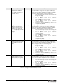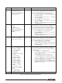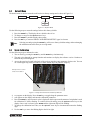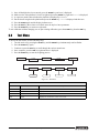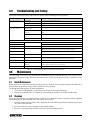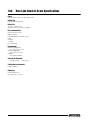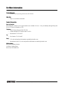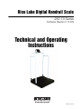
1
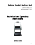
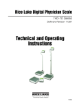
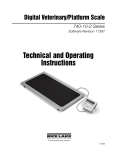
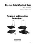
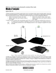
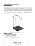
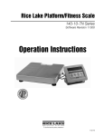
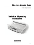
Rice Lake Digital Handrail Scale 250-10 Series Software Revision 111439 Technical and Operating Instructions 152436 - Rev A Contents 1.0 Introduction.................................................................................................................................. 1 2.0 Safety ........................................................................................................................................... 2 2.1 Safety Signals. . . . . . . . . . . . . . . . . . . . . . . . . . . . . . . . . . . . . . . . . . . . . . . . . . . . . . . . . . . . . . . . . . . 2 2.2 Safety Precautions . . . . . . . . . . . . . . . . . . . . . . . . . . . . . . . . . . . . . . . . . . . . . . . . . . . . . . . . . . . . . . . 2 3.0 Scale Assembly ........................................................................................................................... 3 3.1 Unpacking Your Scale . . . . . . . . . . . . . . . . . . . . . . . . . . . . . . . . . . . . . . . . . . . . . . . . . . . . . . . . . . . . 3 3.2 Repacking . . . . . . . . . . . . . . . . . . . . . . . . . . . . . . . . . . . . . . . . . . . . . . . . . . . . . . . . . . . . . . . . . . . . . 3 3.3 Setting Up Your Scale . . . . . . . . . . . . . . . . . . . . . . . . . . . . . . . . . . . . . . . . . . . . . . . . . . . . . . . . . . . . 3 4.0 Scale Operation ........................................................................................................................... 5 4.1 4.2 4.3 4.4 4.5 5.0 Weighing . . . . . . . . . . . . . . . . . . . . . . . . . . . . . . . . . . . . . . . . . . . . . . . . . . . . . . . . . . . . . . . . . . . . . . Hold/Release Function . . . . . . . . . . . . . . . . . . . . . . . . . . . . . . . . . . . . . . . . . . . . . . . . . . . . . . . . . . . . Preset Tare. . . . . . . . . . . . . . . . . . . . . . . . . . . . . . . . . . . . . . . . . . . . . . . . . . . . . . . . . . . . . . . . . . . . . Toggle Tare . . . . . . . . . . . . . . . . . . . . . . . . . . . . . . . . . . . . . . . . . . . . . . . . . . . . . . . . . . . . . . . . . . . . Using the Body Mass Index (BMI) Function. . . . . . . . . . . . . . . . . . . . . . . . . . . . . . . . . . . . . . . . . . . . . 6 6 6 7 7 Scale Configuration ..................................................................................................................... 8 5.1 Programming Mode Menu . . . . . . . . . . . . . . . . . . . . . . . . . . . . . . . . . . . . . . . . . . . . . . . . . . . . . . . . . 9 5.2 Default Menu . . . . . . . . . . . . . . . . . . . . . . . . . . . . . . . . . . . . . . . . . . . . . . . . . . . . . . . . . . . . . . . . . . 13 5.3 Scale Calibration . . . . . . . . . . . . . . . . . . . . . . . . . . . . . . . . . . . . . . . . . . . . . . . . . . . . . . . . . . . . . . . 13 6.0 7.0 Test Menu................................................................................................................................... 14 RS-232 Communication ............................................................................................................. 15 7.1 Push-Button Keypad Print . . . . . . . . . . . . . . . . . . . . . . . . . . . . . . . . . . . . . . . . . . . . . . . . . . . . . . . . 15 7.2 Communication Protocols . . . . . . . . . . . . . . . . . . . . . . . . . . . . . . . . . . . . . . . . . . . . . . . . . . . . . . . . 16 7.2.1 7.2.2 Escape Protocol . . . . . . . . . . . . . . . . . . . . . . . . . . . . . . . . . . . . . . . . . . . . . . . . . . . . . . . . . . . . . . . . . 16 Maintenance Protocol . . . . . . . . . . . . . . . . . . . . . . . . . . . . . . . . . . . . . . . . . . . . . . . . . . . . . . . . . . . . . 18 7.3 USB Connection . . . . . . . . . . . . . . . . . . . . . . . . . . . . . . . . . . . . . . . . . . . . . . . . . . . . . . . . . . . . . . . 18 8.0 9.0 Troubleshooting and Testing ..................................................................................................... 21 Maintenance .............................................................................................................................. 21 9.1 Basic Maintenance . . . . . . . . . . . . . . . . . . . . . . . . . . . . . . . . . . . . . . . . . . . . . . . . . . . . . . . . . . . . . . 21 9.2 Cleaning . . . . . . . . . . . . . . . . . . . . . . . . . . . . . . . . . . . . . . . . . . . . . . . . . . . . . . . . . . . . . . . . . . . . . . 21 10.0 Rice Lake Handrail Scale Specifications.................................................................................. 22 For More Information ............................................................................................................................. 23 Rice Lake Digital Handrail Scale Limited Warranty.............................................................................. 24 Technical training seminars are available through Rice Lake Weighing Systems. Course descriptions and dates can be viewed at www.ricelake.com or obtained by calling 715-234-9171 and asking for the training department © 2012 Rice Lake Weighing Systems. Specifications subject to change without notice. All rights reserved. Rice Lake Weighing Systems is an ISO 9001 registered company. Software revision 11439, September 2013 - Rice Lake continually offers web-based video training on a growing selection of product-related topics at no cost. Visit www.ricelake.com/webinars. i Digital Handrail Scale Technical & Operating Instructions 1.0 Introduction The Rice Lake Digital Handrail Scale is designed for weighing bariatrics and ensures sound, accurate weighing information. A non-skid platform paired with side rails assists persons who need extra support and safety. The scale is set up to use motion sensing weighing technology, to determine the actual weight of a moving patient. The weight is displayed on the indicator and can be displayed in pounds or kilograms. This manual can be viewed and downloaded from the Rice Lake Weighing Systems web Internet site at www.ricelake.com/health. Technical information on this product and other medical products are also available on the Rice Lake Weighing Systems web site. Rice Lake Weighing Systems is an ISO 9001 registered company. Figure 1-1. Rice Lake Digital Handrail Scale (250-10-2) 1 2.0 Safety There are certain precautions that should be taken to prevent personal injury to the user and damage to your scale. 2.1 Safety Signals Safety Signal Definitions: Indicates an imminently hazardous situation that, if not avoided, will result in death or DANGER serious injury. Indicates a potentially hazardous situation that, if not avoided, could result in death or Warning serious injury. Caution Indicates a potentially hazardous situation that, if not avoided, may result in minor or moderate injury. Indicates information about procedures that, if not observed, could result in damage to Important equipment. 2.2 Safety Precautions Do not operate or work on this equipment unless you have read and understand instructions in the manual. Failure to follow the instructions or heed the warnings could result in injury or death. Contact any Rice Lake Weighing Systems dealer for replacement manuals. Proper care is your responsibility. Before attempting to operate this unit, make sure every individual who operates or works Warning with this unit has read and understands the following safety information. Please follow these instructions carefully. • • • • • • • • • • • • • • • 2 Do not drop the scale or subject it to violent shocks. For accurate weighing, the scale must be placed on a flat, stable surface. Do not transport the scale while someone is standing on it. Weight exceeding the maximum capacity (1000 lb/453 kg) may damage your scale. Operating at voltages and frequencies other than specified could damage the equipment. If the LO Bat indicator activates, for accurate weighing, replace the batteries or connect the scale to an AC power source as soon as possible. To avoid cross contamination, the scale should be cleaned regularly. Avoid contact with excessive moisture. Do not allow minors (children) or inexperienced persons to operate this scale. Do not jump up and down on the scale. Do not use in the presence of flammable materials. Do not make alterations or modifications to the scale. People with disabilities, or who are physically frail, should always be assisted by another person when using this scale. Do not use the scale on slippery surfaces, such as a wet floor. Do not use this scale when your body/feet are wet, such as after taking a bath. Digital Handrail Scale Technical & Operating Instructions 3.0 Scale Assembly 3.1 Unpacking Your Scale Place the unopened box in an open area that has ample room for unpacking the scale. Parts contained in the shipping box include: • The scale • This manual • 6 mm Allen key 3.2 Repacking If the Digital Handrail Scale must be returned for modification, calibration or repair, it must be properly packed with sufficient packing materials. Whenever possible, use the original carton when shipping the scale back. Important 3.3 Damage caused by improper packaging is not covered by the warranty. Setting Up Your Scale Move the scale into the area where the weighing process will occur. Place the scale on a hard, level surface for the most accurate weighments. 1. Locate the operator’s manual from inside the box and set aside as it will provide instructions on the proper set up. 2. Using two people, remove the scale out of the packaging material that it came in by lifting the scale out of the box by the scale base. Caution DO NOT lift the scale out of the box by its handle as this can cause the hinges to break. 3. Gently set the scale platform down to the floor. 4. Loosen the handles using the Allen key and unfold handles and set upright. Lift handles up Figure 3-1. Set Up Sides to a Vertical Position 5. 6. 7. 8. Adjust the feet to ensure that the base of the scale base is not touching the floor. Screw in all four legs. Attach the wrap around rails. Tighten the hex screw head using the enclosed 6 mm Allen key to stabilize the scale. Digital Handrail Scale Technical & Operating Instructions - Scale Assembly 3 Inserting Batteries The six AA batteries that come with the scale offer an average of 25 hours of continuous use. To install the batteries, 1. Open the battery chamber cover by loosening the thumbscrew. 2. Insert batteries into the battery chamber as shown in Figure 3-2. Figure 3-2. Battery Chamber 3. Close the battery chamber. If an external power supply or USB power supply is connected, the battery flag on the display is turned off. When using battery or USB power supply, the backlight power is deducted to 60%. AC Power Connections Use the optional 120 VAC or 230 VAC adaptor when power is available. The optional AC power adaptor plugs into the back of the indicator as shown in Figure 3-3. Connect the optional AC power source RS-232 connection Figure 3-3. Power Connection 4 Digital Handrail Scale Technical & Operating Instructions 4.0 Scale Operation The Rice Lake Digital Handrail Scale display has various front panel keys as shown in Figure 4-1. Figure 4-1. Front Panel Display Keys Key Descriptions Table 4-1 describes each of the key functions. Key Name Function On/Off Switches the scale on or off. Print LB/KG Print — A long key press will send data out from the RS-232 port. LB/KG — A short key press allows the user to toggle between kilograms and pounds providing that it’s enabled in configuration mode. There is no toggling while in the BMI mode. Zero Clears the weight off the scale and returns it to zero after three seconds. It works only if the current weight is stable and zero up to 2% of full weight. Hold Release Hold & Release — The first press holds the most current weight value shown on the display. A second press releases the weight value shown. This key is not active while in BMI mode. BMI Enables the user to access the BMI (Body Mass Index) function. This key only works if there is a locked weight shown on the display and the BMI function is turned on in the configuration mode. TARE Used to subtract the weight off the scale, example: oxygen tank, other equipment. CLEAR Allows the user to return to normal weighing when the BMI value is being displayed. While in BMI mode, the height display causes the value to return to the default of 190.0 cm, 5 ft, 7.5 in. On/Off Print LB/KG Zero Hold Release BMI TARE T CLEAR Table 4-1. Rice Lake Digital Handrail Scale Key Functions Digital Handrail Scale Technical & Operating Instructions - Scale Operation 5 Key Name Function ENTER Used to accept height in BMI mode. Accepts the value of the parameter last entered and moves to the next stage. A long press of the ENTER key during the scale’s start up process will enter the ID display (pre-parameter mode). Up/Down Arrows Used to adjust height input (0.5 in/0.5 cm) while in BMI mode. Adjusts the value of the flashing digit/number. ENTER Table 4-1. Rice Lake Digital Handrail Scale Key Functions Caution The keys on the front panel display are very sensitive so only a gentle pushing motion is required to obtain results. The scales have the capability of performing different operations beyond just calculating weight. The various operating instructions are described below. 4.1 Weighing Use the following steps to weigh a person. 1. Press the On/Off key to turn on the scale and 0.0 will appear on the display along with ZERO on the upper display. 2. When the person step on the scale the display shows the person’s weight. The LOCK annunciator is on in the upper display and beeps to indicate the end of the weighing process. 3. To change the display from kg to lb and vice-versa, press the LB/KG key. 4. To turn off the scale, press and hold the On/Off key until OFF appears on the display. 4.2 Hold/Release Function Use the following steps to use the Hold/Release function. 1. When the person is on the scale, press the Hold/Release key. 2. When the person steps off the scale, the weight and the HOLD & LOCK annunciator will remain on the display. 3. At this stage the Zero key will not work. The only way to return to zero from here is to press the Hold/ Release key one more time. Note 4.3 Pressing the Hold key prior to a person getting on the scale will also work. Preset Tare Use the following steps to use the Preset Tare. 1. When the weight is set to 0.0, place the extra load on the scale. Press the TARE key until the display returns to 0.0 and NET appears on the display. 2. Remove the extra load from the scale. The weight will appear with a negative symbol to the left of it. 3. Ask the patient to step on the scale with the extra weight. The display shows the patient’s weight. The NET annunciator is still on. The weight of the extra load remains stored in memory. 4. To cancel the tare weight, press and hold the TARE key until NET disappears from the display and the display turns back to 0.0 and GROSS appears. Tare weight is also cancelled when the scale is turned off. 6 Digital Handrail Scale Technical & Operating Instructions 4.4 Toggle Tare Use the following steps to use the Toggle Tare function. 1. When the weight is set to 0.0, press the TARE key. 2. The default tare value is displayed (default is programmed to be 33.0 lb/15.0 kg), while the zero is flashing. 3. Use the Up/Down arrow keys to adjust the value. 4. Press ENTER to start the tare function and the NET annunciator will be turned on instead of the GROSS annunciator. 4.5 Using the Body Mass Index (BMI) Function Use the following steps in determining the BMI. LB Mode 1. 2. 3. 4. Ensure that the scale is at zero. Have the person step on the scale to obtain a weight. The LOCK annunciator is illustrated on the display. Press the BMI key. The BMI and FT/IN annunciators are lit on the display and a default value of 5 feet and 7.5 inches (5-07.5) is flashing. 5. Use the Up/Down arrow keys to adjust the height value, and press the ENTER key to move to the next step. 6. The BMI value and BMI annunciator is shown on the display. Press CLEAR to return to the weighing mode and the BMI function will be turned off. KG Mode 1. 2. 3. 4. Ensure that the scale is at zero. Have the person step on the scale to obtain a weight. The LOCK annunciator is illustrated on the display. Press the BMI key. The BMI and CM annunciators are lit on the display and a default value of 170.0 cm (170.0) is flashing. 5. Use the Up/Down arrow keys to adjust the height value, and press the ENTER key to move to the next step. 6. The BMI value and BMI annunciator is shown on the display. Press the CLEAR key to return to the weighing mode or step off the scale and the BMI function will be turned off. Digital Handrail Scale Technical & Operating Instructions - Scale Operation 7 5.0 Scale Configuration Options and parameter setup are done through the scale configuration section and is used for setting values, parameters, and options that are essential for the functioning of the scale. Access to the setup switch is located under the tilt stand cover. Use a Phillips head screwdriver to remove the four screws holding the cover in place. (shown in Figure 5-1— left photo). Battery compartment Setup switch location Remove four screws to access setup switch Figure 5-1. Setup Switch Location Use the following steps to enter into configuration mode. 1. Make sure the scale is turned off. 2. Turn the scale on by simultaneously pressing the On/Off key and the ENTER key. 3. Continue to hold both keys until Id appears. The unit cycles through its startup function and continues to display the software version. 4. Access the recessed setup switch located in the back of the indicator. You can use a small paper clip, small screwdriver or other similar object to press the setup switch. 5. Once the setup switch is pressed, PROG appears on the display. 6. The scale can be configured using a series of menus accessed through the front panel when the scale is in setup mode. PROG CALIB DEF DONE Figure 5-2. Top Level Menu 7. Press the BMI key to advance to the desired menu. 8. Press the ENTER key and advance in the manual to the related menu selection for further instructions. 8 Digital Handrail Scale Technical & Operating Instructions 5.1 Programming Mode Menu Various parameters can be set while in programming mode. Those parameters are shown in Figure 5-3. PROG CALIB FULL DONE DEF OP TOFF UNITS TEST ATOUT ALEN Value Value ATOL Value Kg/Lb 5 Kg 4 Lb 3 Value 2 1 0 9 8 7 6 LOAD ASTART ARW SAL value Value Value Value P00 P01 P02 P03 P04 P00-1 P01-0 P02-1 P03-0 P04-1 ROUND DISP BAUD 0.2 0.0 96 0.5 0 48 1.0 0.0000 1152 2.0 0.000 576 5.0 0.00 384 10.0 288 20.0 192 0.1 144 Figure 5-3. Programming Mode Menu Structure Table 5-1 lists the various display messages and sequence when setting up the scale. Parameter FULL Description Full capacity of the scale Choices Steps Value (1000 lb) The display toggles between a numeric value and FULL. If you don’t want to change the value, press the BMI key to move to the next setting. Example: from FULL to LOAD. If you want to change the value, use the following steps. 1. Press the ENTER key to change value starting with the right most digit. 2. Use the Up/Down arrow keys to increment/ decrement numbers. 3. Press the BMI key to move to the left. 4. Use the Up/Down arrow keys to increment/ decrement numbers. 5. Press the BMI key again to move to the left 6. Use the Up/Down arrow keys to increment/ decrement numbers. 7. When done press the ENTER key to move to the next parameter (LOAD). Table 5-1. Configuration Mode Menu Digital Handrail Scale Technical & Operating Instructions - Scale Configuration 9 Parameter Description Choices Steps LOAD This is the amount of weight applied during calibration. Can also be changed in the calibration menu. Value (200 Lb) The display toggles between a numeric value and LOAD. If you don’t want to change this value, press the BMI key to move to the next setting. Example: from LOAD to ASTART. If you want to change the value, use the following steps. 1. Press the ENTER key to change value starting with the right most digit. 2. Use the Up/Down arrow keys to increment/ decrement numbers. 3. Press the BMI key to move to the left. 4. Use the Up/Down arrow keys to increment/ decrement numbers. 5. When done, press the ENTER key to move to the next parameter (ASTART). ASTART Weight process start limit — Maximum (full capacity)/10. Determine when the weight algorithm starts (when the “----” is displayed), below this value the scale will show live weight. Value (2.0) The display toggles between a numeric value and ASTART. If you don’t want to change this value, press the BMI key to move to the next setting. Example: from ASTART to ARW. If you want to change the value, use the following steps. 1. Press the ENTER key to change value starting with the right most digit. 2. Use the Up/Down arrow keys to increment/ decrement numbers. 3. Press the BMI key to move to the left. 4. Use the Up/Down arrow keys to increment/ decrement numbers. 5. When done, press the ENTER key to move to the next parameter (ARW). ARW Auto Reweigh — Restarts the weight algorithm if the weight changed by more than this value. Value (4.0 Lb) The display toggles between a numeric value and ARW. If you don’t want to change this value, press the BMI key to move to the next setting. Example: from ARW to SAL. If you want to change the value, use the following steps. 1. Press the ENTER key to change value starting with the right most digit. 2. Use the Up/Down arrow keys to increment/ decrement numbers. 3. Press the BMI key to move to the left. 4. Use the Up/Down arrow keys to increment/ decrement numbers. 5. When done, press the ENTER key to move to the next parameter (SAL). SAL Semi Auto Live —This value is the interval between weight displays during the algorithm process. Value (0.5) The display toggles between a numeric value and SAL. If you don’t want to change this value, press the BMI key to move to the next setting. Example: from SAL to ROUND. If you want to change the value, use the following steps. 1. Press the ENTER key to change value starting with the right most digit. 2. Use the Up/Down arrow keys to increment/ decrement numbers. 3. When done, press the ENTER key to move to the next parameter (ROUND). Table 5-1. Configuration Mode Menu (Continued) 10 Digital Handrail Scale Technical & Operating Instructions Parameter ROUND Description Choices Scale Resolution — Values in kg: 1, 2, 5, 10, 20, 50, 100 Values in lb: 1, 2, 5, 10, 20, 50, 100, 200 DISP Steps 0.2 0.5 1.0 2.0 5.0 10.0 20.0 0.1 The display toggles between a numeric value and ROUND. The decimal point location is set to the DISP parameter display decimal point location. If you don’t want to change this value, press the BMI key to move to the next setting. Example: from ROUND to DISP. If you want to change the value, use the following steps. 1. Press the ENTER key to change value. 2. Press the Up/Down arrow keys to change the available parameters. 3. When done, press the ENTER key to move to the next parameter (DISP). 0.0 0 0.0000 0.000 0.00 The display toggles between a numeric value and DISP. If you don’t want to change this value, press the BMI key to move to the next setting. Example: from DISP to BAUD. If you want to change the value, use the following steps. 1. Press the ENTER key to change value. 2. Use the Up/Down arrow keys to change the available parameters. 3. When done, press the ENTER key to move to the next parameter (BAUD). BAUD Baud rate 96 48 1152 576 384 288 192 144 Note: Indicator display illustrates first two digits of baud rate only. The display toggles between a numeric value and baud. If you don’t want to change this value, press the BMI key to move to the next setting. Example: from BAUD to ATOL. If you want to change the value, use the following steps 1. Press the ENTER key to change value. 2. Use the Up/Down arrow keys to change the available parameters. 3. When done, press the ENTER key to move to the next parameter (ATOL). ATOL Algorithm initial tolerance — Maximum value is 255. Values above 255 will not let you proceed and will return to the previous value. Value (10) The display toggles between a numeric value and ATOL If you don’t want to change this value, press the BMI key to move to the next setting. Example: from ATOL to ALEN. If you want to change the value, use the following steps. 1. Press the ENTER key to change value starting with the right most digit. 2. Use the Up/Down arrow keys to increment/ decrement numbers. 3. Press the BMI key to move to the left. 4. When done, press the ENTER key to move to the next parameter (ALEN). ALEN Algorithm initial exponent — Maximum value 10. Values above 10, will not let you proceed and will return to the previous value. Value (8) The display toggles between a numeric value and ALEN. If you don’t want to change this value, press the BMI key to move to the next setting. Example: from ALEN to ATOUT. If you want to change the value, use the following steps. 1. Press the ENTER key to change value starting with the right most digit. 2. Use the Up/Down arrow keys to increment/ decrement numbers. 3. When done, press the ENTER key to move to the next parameter (ATOUT). Table 5-1. Configuration Mode Menu (Continued) Digital Handrail Scale Technical & Operating Instructions - Scale Configuration 11 Parameter Description Choices Steps ATOUT Algorithm maximal exponent — Maximum value is 15. Values above 15, will not let you proceed and will return to the previous value. Value (10) The display toggles between a numeric value and ATOUT. If you don’t want to change this value, press the BMI key to move to the next setting. Example: from ATOUT to TOFF. If you want to change the value, use the following steps. 1. Press the ENTER key to change value starting with the right most digit. 2. Use the Up/Down arrow keys to increment/ decrement numbers. 3. Press the BMI key to move to the left. 4. Use the Up/Down arrow keys to increment/ decrement numbers. 5. When done, press the ENTER key to move to the next parameter (TOFF). TOFF Auto off timer — Measured in minutes. 0 = always on. Maximum is 9 minutes. When using an external power supply, this parameter is irrelevant. 5 4 3 2 1 0 9 8 7 6 The display toggles between a numeric value and TOFF. If you don’t want to change this value, press the BMI key to move to the next setting. Example: from TOFF to UNITS. Press the ENTER key to move to the next parameter. (UNITS). If you want to change the value, use the following steps. 1. Press the ENTER key to change values. 2. Use the Up/Down arrow keys to change the available parameters. 3. When done, press the ENTER key to move to the next parameter (UNITS). UNITS Units — Selects the unit of measure. It can be either Kg/Lb, Kg only or Lb only. KG/LB KG LB The display toggles between unit of measurements and UNIT. If you don’t want to change this value, press the BMI key to move to the next setting. Example: from UNITS to OP. If you want to change the value, use the following steps. 1. Press the ENTER key to change values. 1. Press the Up/Down arrow keys to change the value. 2. When done, press the ENTER key to move to the next parameter (OP). OP Binary options: OP0 — Live weighing options (0=disable, 1=enable) OP1 — Communication protocol (0=ESC, 1=maintenance) OP2 — BMI menu (0=disable, 1=enable) OP3 — RTC power (0=disable, 1=enable) OP4 - Semi-Auto-Live — (0=disable, 1=enable) OP5 - Full calculation — (0=spatial, 1=multiply by (0=disable, 1=enable OP6 - Tare - (0=disable, 1=enable OP7 - Bat type — (0=dry batteries, 1=rechargeable batteries) OP8 — OIML mode (0=disable, 1=enable OP0 OP1 OP2 OP3 The display toggles between a binary option and POO-0. If you don’t want to change this value, press the BMI key to move to the next setting. If you want to change the value, use the following steps. 1. Press ENTER to change parameters. 2. Use the Up/Down arrow keys to select the display value you want to change. 3. Press the BMI key to move the flashing cursor. 3a. Use the Up/Down arrows to change the value. 3b. Press the BMI key to move the flashing cursor. 4. Press the ENTER key to save all of the display parameters. SAVE appears on the display. 5. Press the ENTER key again and DONE appears indicating that you are now done entering all of the parameters of the scale. Press the BMI key to cycle back to the top level menu choices, ie: PROG/CALIB/DEF/DONE/TEST Table 5-1. Configuration Mode Menu (Continued) 12 Digital Handrail Scale Technical & Operating Instructions 5.2 Default Menu The default menu is used to return the scale back to its factory settings and is shown in Figure 5-4. PROG CALIB DEF DONE TEST NO YES Figure 5-4. Default Menu Use the following steps to return the settings back to their factory default. 1. Press the ENTER key. The display shows a default value of NO. 2. To change to YES, press the Up/Down arrow keys. 3. Press the ENTER key and the display shows DONE. 4. Press the BMI key to return to PROG/CALIB/DEF/DONE/TEST upper level menu. Selecting YES and pressing the ENTER key will reset to factory defaults settings without changing Note the calibration and will return you to weigh mode. 5.3 Scale Calibration Use the following steps to calibrate the scale. 1. Turn on scale by pressing the On/Off key and the ENTER key simultaneously. 2. The unit cycles through its startup function and continues to display the software version. Continue to hold both keys until Id appears. 3. Access the setup key located in the back of the scale to enter the setup parameters for the scale. You can use a small paper clip, small screwdriver or other similar object to press the setup key. Setup switch location on back of indicator. Figure 5-5. Setup Switch Location on Back of Indicator 4. Prog appears on the display. Press the BMI key to toggle along the parameter menu. 5. Calib appears on the display and enter the calibration parameters. 6. Press the ENTER key and a numeric value is displayed which represents the amount of weight that is used for calibration. Lb will be flashing. To switch between lb and kg, press the Up/Down arrow keys on the display. Once a unit is selected, press ENTER and the right most digit will be flashing. 7. To change the calibration load value, use the Up/Down arrow keys to increment/decrement the flashing digit. 8. Use the BMI key to move the flashing digit to the left or right. Digital Handrail Scale Technical & Operating Instructions - Scale Configuration 13 9. Once all the digits have been entered, press the ENTER key and Clear is displayed. 10. Make sure the scale platform is clear of weight and press the ENTER key again and ===== is displayed. 11. A request to put the chosen load on the platform is displayed by Put xxx.xx. 12. Put the chosen weight on the platform and press the ENTER key. ===== is displayed and then Save. 13. Press the ENTER again and the display indicates Done. 14. Press the BMI key three times to exit back out to the top level Done parameter. 15. Press the ENTER key to return to weigh mode. To exit calibration without changing zero or span existing calibration, press the CLEAR key, then the BMI key. 6.0 Test Menu To access the TEST menu, use the following steps. 1. Turn the scale on by pressing the On/Off key and the ENTER key simultaneously until ID flashes. 2. Press the ENTER key again. 3. Continue to press the BMI key to scroll through the various menu items. 4. Once complete, press the BMI key again and Done is displayed. 5. Press the ENTER key to start the weighing process. PROG CALIB DEF DONE TEST VER BAT VALUE A2D 1.83 value value Figure 6-1. Test Menu Test Menu Parameter Choice Description VER Value Displays the current software version. BAT Value Displays the current battery level. VALUE Value Displays the actual value. A2D Value Displays the actual raw counts of the scale. Table 6-1. Test Menu 14 Digital Handrail Scale Technical & Operating Instructions value 7.0 RS-232 Communication The scale comes with an RS-232 port that enables weight data to be transmitted to other equipment, such as a computer or printer. The RS-232 cable with DB-9 connector (PN 100719) is available from Rice Lake Weighing Systems. Figure 3-3 on page 4 shows where the RS-232 connection is. The RS-232 parameters are 9600 baud (selectable in the programming mode), 8 data bits, 1 stop bit, no parity and no handshaking. There are three methods of communication: • Pushbutton keypad print • Escape protocol • Maintenance protocol 7.1 Pushbutton Keypad Print With a stable, in-range weight, press and hold the LB/KG/Print key for at least three seconds, or until the scale displays PRINT. Note that if the scale does not beep after five seconds, then release the button as the weight was either in motion, or out of range. • If displaying weight and not BMI, the scale will send out the following 21 character string: xxxxxxxxx<SP>uu<SP>mmmmm<SP><CR><LF> Where: xxxxxxxxx is the weight with decimal point and " - " sign, if negative uu is the unit (lb or kg). mmmmm is the mode (gross or net) Example: 60.1 KG= <PATIENT><SP><WEIGHT><SP>-60.1<SP>KG<SP><CR><LF> • In BMI mode (displaying the BMI value), the scale will send out the following data: PATIENT WEIGHT PATIENT HEIGHT PATIENT BMI 60.1 KG 170.0 CM 20.8 Example in KG: <PATIENT><SP><WEIGHT><SP>-60.1<SP>KG<SP><CR><LF> <PATIENT><SP><HEIGHT><SP>-170.0<SP>CM<SP><CR><LF> <PATIENT><SP><B><SP><M><SP><I><SP><SP><SP><20.8<SP><SP><SP><SP><CR><LF> Example in LB: <PATIENT><SP><WEIGHT><SP>132.4<SP>LB<SP><CR><LF> <PATIENT><SP><HEIGHT><SP>-5-07.5<SP>FT<SP><CR><LF> <PATIENT><SP><B><SP><M><SP><I><SP><SP><SP><20.4<SP><SP><SP><SP><CR><LF> In case of under weight or over weight, the word Under or Over will be sent correspondingly. Digital Handrail Scale Technical & Operating Instructions - RS-232 Communication 15 7.2 Communication Protocols The Rice Lake Digital Handrail Scale has two communication protocols, escape and maintenance protocol. 7.2.1 Escape Protocol An escape protocol is where the escape (0X1B or ASCII 27) is used to indicate that there is a command following. On the PC side there must be a listener created by the vendor that will interpret this protocol. This listener must also take care of all the issues regarding data integrity, etc. to make sure that the data that was sent and received is valid. Two examples include: • Scale initiated communication • PC initiated communication Table 7-1 is what can be sent across communications lines. PC Initiated ESC Value Request current values/settings R Diagnostics A Send scale control messages C PC Initiated ESC Value Send single reading R Send diagnostic response Table 7-1. Escape Protocol Commands Table 7-2 lists the ESC characters that will be used. ESC character ESC value with parameters Reading R R Tells the PC that the scale is sending a reading. Immediately following this is the value that is sent. Example: <ESC><R>ESC><W0200.0<ESC>Nm<ESC>E Weight W Wnnn.n Is the patient weight (example: W02000 means 200.0). If the scale is overloaded or under loaded, the scale will return the value 999.99. Height H Hnnn.n Patient height BMI B Bnn.n Patient BMI Units N Nc Indicates in which unit the values have been taken (m=metric, c=constitutional). End of Packet (EOP) E E Indicates that the end of the command has been reached. Diagnostics (request) A Accc A request for a diagnostic test on certain parts of the scale (such as battery life, load cells). Diagnostics (response) Z Zccc This will be the response of the diagnostics done on the scale. Values will include error codes to indicate what is wrong with the scale, or all zeros (Z000) to indicate that all is well. Control (set a value) C Cccc=c Sets the value of the scale’s global settings. Example: <ESC><CUOM=m><ESC><E will set the unit of measurement. Name Description Table 7-2. ESC Characters Name of Control Unit of Measure (metric or constitutional) Identifier UOM Table 7-3. Scale Global Values List and Identifiers 16 Digital Handrail Scale Technical & Operating Instructions Unit c (m or c) Samples of Escape Protocol Figure 7-1 and 7-2 show what the diagrams will look like on the PC as the scale measures weight and sends over this communications line: &4$3&4$& 3#!,%0# 3FBEJOH SFRVFTU &01 Figure 7-1. Sample of Escape Protocol &4$3&4$8&4$/N&4$& 3FBEJOH $PNNBOE 6OJUPG.FBTVSF.FUSJD &01 8FJHIU Figure 7-2. Sample of Escape Protocol When the user wants to diagnose the problems on the scale, it looks like the Figure 7-3 and 7-4. DIRECTIONOFCOMMUNICATION 3#!,%0# &4$"#"5&4$& %JBHOPTFCBUUFSZ &01 Figure 7-3. Diagnose the Escape Protocol Diagram &4$;&6&4$& #BUUFSZJTPLBZ OPFSSPST &01 &4$;&-&4$& #BUUFSZJTWFSZMPX 6OTUBCMF &01 Figure 7-4. Diagnose Battery Protocol Diagram Digital Handrail Scale Technical & Operating Instructions - RS-232 Communication 17 7.2.2 Maintenance Protocol Table 7-4 lists the maintenance protocol commands. Command Definition R Reboot V Firmware ID + development version W Current weight A Current AD Z Zero the scale F Show flash values (used for the first flash process) L USB On/Off (not available on USB communication Table 7-4. Maintenance Protocol Commands 7.3 USB Connection The Rice Lake Digital Physician Scale has the capability of connecting to a PC using a USB connection and a USB cable (not included). That connection location is shown in Figure 7-5. USB Connection Figure 7-5. USB Connection Port Connecting software and downloads should be addressed by your IT department and can vary depending on what type of computer platform you’re using. Basic information on USB driver installation using Windows ® is described below and serves only as an example. 1. Figure 7-6 shows the window that pops up when the USB cable is connected and the scale is turned on. Figure 7-6. Hardware Wizard Found Screen 18 Digital Handrail Scale Technical & Operating Instructions Follow the on screen prompts to navigate through the screens shown below. 2. Select No, not this time and then select Next. 3. Select Install the software automatically then select Next. 4. The following screen appears while the driver is installing on to your system. Digital Handrail Scale Technical & Operating Instructions - RS-232 Communication 19 5. The following screen appears when installation is complete. Click on Finish. 6. If you want to verify the installation, you can view the driver by looking at the device manager of your system. 20 Digital Handrail Scale Technical & Operating Instructions 8.0 Troubleshooting and Testing Refer to the following to check and correct any failure before contacting service personnel. Symptom Scale does not turn on Questionable weight or the scale does not zero Possible Cause Corrective Action Dead battery Connect the scale to a power source. Faulty electrical outlet Use a different electrical outlet. Bad power supply Replace adaptor. External object is interfering with the scale. Remove the interfering object from the scale. Display did not show 0.0 before weighing. Help the patient off the scale, zero the scale and begin the weighing process again. Scale is not placed on a level floor. Ensure the scale is level and begin the weighing process again. Scale is out of calibration. Check the weight with a known weight value. The display shows E messages as detailed below. E06 Identifier - ADC E07 AD too high AD too low E10 Overload Scale has been overloaded. Remove load from scale. E4L BAT Battery low but still useable — 1 bar left on the indicator display. Battery low and unstable — no bars left on the indicator display. E4U E11 CAL Calibration Error — recalibrate the scale again. Err 2 Low saturation state (low A/D) The load cell is not connected properly. Check the cables and mechanical connections. If the problem persists, replace the set of load cells. Err 3 High saturation state (high A/D) See Err 2. Err 6 Unstable weight. Cannot calibrate. Check the load cells’ mechanical surroundings and see that nothing touches them and that the cables are properly welded. SAT Damaged load cell cable Replace load cell cable. Table 8-1. Troubleshooting Table for the Rice Lake Scale Line 9.0 Maintenance The following section provides instructions for maintaining and cleaning the Rice Lake line of scales. Maintenance operations other than those described in this section should be performed by qualified service personnel. 9.1 Basic Maintenance Before the first use of the scale and after periods of non-use, check the scale for proper operation and function. If the scale does not operate correctly, contact qualified service personnel. Go through the following steps for basic maintenance. 1. Check the overall appearance of the entire scale for any obvious signs of damage. 2. Inspect the condition of the AC adaptor for cord cracking or fraying or for broken or bent prongs. 9.2 Cleaning Proper care and cleaning is essential to ensure a long life of accurate and effective operation. Before beginning the cleaning process, disconnect the scale from the AC power source. 1. Clean all external surfaces with a clean, damp cloth or tissue. Mild soap and water solution may be used. Dry with a clean soft cloth. 2. Do not immerse the scale in cleaning or other liquid solutions. 3. Do not use isopropyl alcohol or other solutions to clean the display surface. Digital Handrail Scale Technical & Operating Instructions - Troubleshooting and Testing 21 10.0 Rice Lake Handrail Scale Specifications Power 120 VAC-9VDC-60Hz / 230 VAC-9VDC-50Hz Battery Type 6 AA size Alkaline batteries Battery Use 25 hours continuous use Automatic power-off can be configured Data Communications RS-232 with RJ-45 jack USB Connection Selectable baud rate, default - 9600 8 bits No parity 1 stop bit No handshaking Environmental Operating Temperature 50 to +95°F (10 to 35°C) Storage Temperature 32 to 122°F (0 to 50°C) Humidity 85% relative humidity Capacity and Graduation 1000 lb (453 kg) 0.2 lb (0.1kg) Certifications and Approvals RoHS Compliant Dimensions Platform Dimensions 25 in W x 20 in L x 3 in H 22 Digital Handrail Scale Technical & Operating Instructions For More Information System Manuals • Handrail Scale Operating Instructions, PN 151641 Web Site • http://www.ricelake.com/health Contact Information Hours of Operation Knowledgeable customer service representatives are available 6:30 a.m. - 6:30 p.m. Monday through Friday and 8 a.m. to 12 noon on Saturday. (CST) Telephone Fax • • • Sales/Technical Support 800-472-6703 Canada and Mexico Customers 800-321-6703 International 715-234-9171 • Fax Number 715-234-6967 Email • • U.S. sales and product information at [email protected] International (non-U.S.) sales and product information at [email protected] Mailing Address Rice Lake Weighing Systems 230 West Coleman Street Rice Lake, WI 54868 USA Digital Handrail Scale Technical & Operating Instructions - Rice Lake Handrail Scale Specifications 23 Rice Lake Digital Handrail Scale Limited Warranty Rice Lake Weighing Systems (RLWS) warrants that all RLWS equipment and systems properly installed by a Distributor or Original Equipment Manufacturer (OEM) will operate per written specifications as confirmed by the Distributor/OEM and accepted by RLWS. All systems and components are warranted against defects in materials and workmanship for two years. RLWS warrants that the equipment sold hereunder will conform to the current written specifications authorized by RLWS. RLWS warrants the equipment against faulty workmanship and defective materials. If any equipment fails to conform to these warranties, RLWS will, at its option, repair or replace such goods returned within the warranty period subject to the following conditions: • Upon discovery by Buyer of such nonconformity, RLWS will be given prompt notice with a detailed explanation of the alleged deficiencies. • Individual electronic components returned to RLWS for warranty purposes must be packaged to prevent electrostatic discharge (ESD) damage in shipment. Packaging requirements are listed in a publication, Protecting Your Components From Static Damage in Shipment, available from RLWS Equipment Return Department. • Examination of such equipment by RLWS confirms that the nonconformity actually exists, and was not caused by accident, misuse, neglect, alteration, improper installation, improper repair or improper testing; RLWS shall be the sole judge of all alleged non-conformities. • Such equipment has not been modified, altered, or changed by any person other than RLWS or its duly authorized repair agents. • RLWS will have a reasonable time to repair or replace the defective equipment. Buyer is responsible for shipping charges both ways. • In no event will RLWS be responsible for travel time or on-location repairs, including assembly or disassembly of equipment, nor will RLWS be liable for the cost of any repairs made by others. THESE WARRANTIES EXCLUDE ALL OTHER WARRANTIES, EXPRESSED OR IMPLIED, INCLUDING WITHOUT LIMITATION WARRANTIES OF MERCHANTABILITY OR FITNESS FOR A PARTICULAR PURPOSE . N EITHER RLWS NOR DISTRIBUTOR WILL, IN ANY EVENT, BE LIABLE FOR INCIDENTAL OR CONSEQUENTIAL DAMAGES. RLWS AND BUYER AGREE THAT RLWS’S SOLE AND EXCLUSIVE LIABILITY HEREUNDER IS LIMITED TO REPAIR OR REPLACEMENT OF SUCH GOODS. IN ACCEPTING THIS WARRANTY, THE BUYER WAIVES ANY AND ALL OTHER CLAIMS TO WARRANTY. SHOULD THE SELLER BE OTHER THAN RLWS, THE BUYER AGREES TO LOOK ONLY TO THE SELLER FOR WARRANTY CLAIMS. NO TERMS, CONDITIONS, UNDERSTANDING, OR AGREEMENTS PURPORTING TO MODIFY THE TERMS OF THIS WARRANTY SHALL HAVE ANY LEGAL EFFECT UNLESS MADE IN WRITING AND SIGNED BY A CORPORATE OFFICER OF RLWS AND THE BUYER. © 2012 Rice Lake Weighing Systems, Inc. Rice Lake, WI USA. All Rights Reserved. RICE LAKE WEIGHING SYSTEMS • 230 WEST COLEMAN STREET • RICE LAKE, WISCONSIN 54868 • USA 24 Digital Handrail Scale Technical & Operating Instructions 230 W. Coleman St. Rice Lake, WI 54868 USA U.S. 800-472-6703 Canada/Mexico 800-321-6703 International 715-234-9171 Europe +31 (0) 88 2349171 www.ricelake.com www.ricelake.mx www.ricelake.eu www.ricelake.co.in m.ricelake.com PN 152436, Rev A 09/2013