1
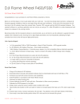
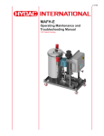
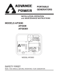
BATTERY CHARGER
OWNER’S MANUAL
BATTERY CHARGER
OWNER’S MANUAL
POWER CHARGER Part # 74016
POWER CHARGER Part # 74016
12-16 volt Amp
12-16 volt Amp
----CAUTION---READ THIS MANUAL CAREFULLY FOR
RULES OF SAFE OPERATION AND
PROPER USE OF THIS CHARGER
----CAUTION---READ THIS MANUAL CAREFULLY FOR
RULES OF SAFE OPERATION AND
PROPER USE OF THIS CHARGER
***SAVE THESE INSTRUCTIONS***
***SAVE THESE INSTRUCTIONS***
CAUTION DO NOT USE WITH LITHIUM BATTERIES !
DO NOT SHUT OFF GENERATOR BEFORE CHARGER.
NOT RECOMMENDED FOR GENERATORS LESS THAN
1200 WATTS.
STANDARD FEATURES
♦ BATTERY TYPE SWITCH (BTS)
♦ HIGH ENERGY RETURN, FAST CHARGING
♦ CONSTANT CURRENT FIRST STAGE
♦ DUAL VOLTAGE LIMIT (CYCLIC/ STANDBY)
♦ AUTOMATIC SAFTEY OVERRIDE TIMER
♦ START DELAY ON BATTERY CONNECT
♦ SHORT AND REV. CONNECTION SHUTDOWN
♦ RUGGED SCR PHASE CONTROL
♦ MAINS ZERO-CROSSING BATTERY SENSING
For Technical Assistance, Call Moroso’s Tech Line at
(203) 458-0542, 458-0546 8:30am – 5:00pm Eastern Time
For Technical Assistance, Call Moroso’s Tech Line at
(203) 458-0542, 458-0546 8:30am – 5:00pm Eastern Time
MOROSO PERFORMANCE PRODUCTS, INC
80 CARTER DR • GUILFORD, CT 06437
Phone: (203) 453-6571 • Fax: (203) 453-6906
Rev. C
090612
Visit Us At www.moroso.com
MOROSO PERFORMANCE PRODUCTS, INC
80 CARTER DR • GUILFORD, CT 06437
Phone: (203) 453-6571 • Fax: (203) 453-6906
74016INST
Rev. C
090612
Visit Us At www.moroso.com
74016INST
Installation Instructions Cont.
Page 2 of 17
Installation Instructions Cont.
POWER CHARGER
12 & 16 VOLT
SPECIFICATIONS
Page 2 of 17
POWER CHARGER
12 & 16 VOLT
SPECIFICATIONS
POWER CHARGER
P/N 74016
INPUT: 117 Volts AC 60Hz, 720 VA 7amps
OUTPUT: 12 or 16 Volts DC, 30 Amps
POWER CHARGER
P/N 74016
INPUT: 117 Volts AC 60Hz, 720 VA 7amps
OUTPUT: 12 or 16 Volts DC, 30 Amps
Full Wave Phase Controlled Rectification
CONTROL:
Voltage limit:
Normal Mode 2.42 V/Cell
Gel-Cell Mode 2.33 V/Cell
Liquid Electrolyte Mode 2.62 V/Cell
Current limited to AMP rating MEAN DC.
Automatic timer starts when first stage voltage limit reached.
Proportional CV stage timer - t/2+1 hour.
Constant voltage 2.3 V/Cell after timeout, with
Temperature Compensation.
PROTECTION:
Electronic reverse polarity. Short circuit shutdown
and current limit.
Manual Reset Circuit Breaker
PROTECTION:
Electronic reverse polarity. Short circuit shutdown
and current limit.
Manual Reset Circuit Breaker
BATTERY TYPE & RATING
This charger is for use with Lead Acid Batteries of
Minimum capacity 50 AH, Gel Cell, Absorbed
Electrolyte or Liquid Electrolyte types by using the
BTS (Battery Type Switch) (See Page 14-16 BTS)
BATTERY TYPE & RATING
This charger is for use with Lead Acid Batteries of
Minimum capacity 50 AH, Gel Cell, Absorbed
Electrolyte or Liquid Electrolyte types by using the
BTS (Battery Type Switch) (See Page 14-16 BTS)
DIMENSIONS: (Inches) (Wall & Table Mounting)
12.0” LONG, 7.0” WIDE, 7.0” HIGH
DIMENSIONS: (Inches) (Wall & Table Mounting)
12.0” LONG, 7.0” WIDE, 7.0" HIGH
090612
Installation Instructions Cont.
Page 3 of 17
IMPORTANT SAFETY
INSTRUCTIONS
1. SAVE THESE INSTRUCTIONS-- This manual contains
important safety and operating instructions.
2. Before using this battery charger, read all instructions and
cautionary markings on (1) the battery charger, (2) the
battery, (3) product using the battery.
3. CAUTION--To reduce risk of injury, charge only lead acid,
maintenance free or flooded lead acid type rechargable
batteries. Other types of batteries may burst causing
personal injury and damage.
4. Do not expose charger to rain or snow.
5. Use of an attachment not recommended or sold by the
battery charger manufacturer may result in a risk of fire,
electric shock or injury to person.
6. To reduce risk of damage to electric plug and cord, pull by
plug rather than cord when disconnecting charger.
7. Make sure cord is located so that it will not be stepped on,
tripped over or otherwise subjected to damage or stress.
8. An extension cord should not be used unless absolutely
necessary. Use of improper extension cord could result
in risk of fire and electrical shock. If an extension cord
must be used, make sure:
a. That pins on plug of the extension cord are the same
number, size and shape as those of the plug on the charger.
b. That the extension cord is properly wired and in good
electrical condition.
c. That the wire size is large enough for the A/C ampere
rating of the charger as specified in the table below:
LENGTH OF CORD (FEET) 25 50 100 150
AWG WIRE SIZE
18 18 16 14
9. Do not operate charger with damaged cord or plug.
REPLACE THEM IMMEDIATELY.
Installation Instructions Cont.
Page 4 of 17
10. Do not operate charger if it has received a sharp blow,
been dropped or otherwise damaged in any way; return it to
a qualified service source.
11. Do not disassemble charger; Take it to a qualified service
source when repair or service is required. Incorrect
reassembly may result in a risk of electrical shock or fire.
12. To reduce risk of electrical shock, unplug charger from
outlet before attempting any maintenance or cleaning.
WARNING
RISK OF EXPLOSIVE GASES
1. WORKING IN VICINITY OF A LEAD-ACID BATTERY IS
DANGEROUS. BATTERIES GENERATE EXPLOSIVE GASES
DURING NORMAL BATTERY OPERATION. FOR THIS
REASON, IT IS OF THE UTMOST IMPORTANCE THAT EACH
TIME BEFORE USING YOUR CHARGER, YOU READ THIS
MANUAL AND FOLLOW THE INSTRUCTIONS EXACTLY.
2. To reduce risk of battery explosion, follow these directions and
those published by the battery manufacturer and the manuf.
of any equipment you intend to use in vicinity of the battery.
Review cautionary marking on these products and on engine.
PERSONAL PRECAUTIONS
1. Someone should be within range of your voice or close enough
to come to your aid when you work near a lead-acid battery.
2. Have plenty of fresh water and soap nearby in case battery
acid contacts skin, clothing or eyes.
3. Wear complete eye protection and clothing protection. Avoid
touching eyes while working near battery.
4. If battery acid contacts skin or clothing, wash immediately with
soap and water. If acid enters eyes, immediately flood eyes
with running cold water for at least 10 minutes and get
medical attention immediately.
5. NEVER smoke or allow a spark or flame in the vicinity of
battery or engine.
Installation Instructions Cont.
Page 5 of 17
6. Be extra cautious to reduce risk of dropping a metal tool onto
battery. It might spark or short circuit battery or other electrical
part that may cause explosion.
7. Remove personal metal items such as rings, bracelets.
necklaces, and watches when working with a lead acid battery.
A lead acid battery can produce a short circuit current high
enough to weld a ring or the like to metal, causing a severe
burn.
8. Use charger for charging a LEAD-ACID BATTERY ONLY. Do
not use battery charger for charging dry-cell batteries that are
commonly used with home appliances. These batteries may
burst and cause injury to persons and damage to property.
9. NEVER charge a frozen battery.
PREPARING TO CHARGE
1. If necessary to remove battery from vehicle to charge, always
remove grounded terminal from battery first. Make sure all
accessories in vehicle are off so as not to cause an arc.
2. Be sure area around battery is well ventilated while battery is
being charged. Gas can be forcefully blown away by using a
piece of cardboard or other nonmetallic material as a fan.
3. Clean all battery terminals. Be careful to keep corrosion from
coming in contact with eyes.
4. Add distilled water in each cell until battery acid reaches level
specified by battery manufacturer. This helps purge excessive
gas from cells. Do not overfill. For a battery without cell caps,
carefully follow manufacturer's recharging instructions.
5. Study all battery manufacturer's specific precautions such as
removing or not removing cell caps while charging and
recommended rates of charge.
6. Determine voltage of battery by referring to car or equipment
owner's manual and make sure it matches output rating of
battery charger.
Installation Instructions Cont.
Page 6 of 17
VOLTAGE SELECTOR SWITCH
WARNING: The front panel switch has two settings, marked
12V and 16V, with OFF in the center.
The switch must be set to 12 Volts when charging 12 Volt
(SIX CELL) batteries.
The switch must be set to 16 Volts ONLY when charging
16 Volt (EIGHT CELL) batteries.
Sixteen Volt (Eight Cell) batteries are special high performance
batteries used in racing applications only, which need a higher
voltage recharge. They are identified as 16 Volts on the battery
label, and have eight cell caps on top of the battery.
Some 16 Volt batteries have a third 12 Volt post. Setting the
charger to 16 Volts, when connected to the “12-Volt Post”
on a three terminal 16 Volt battery, will apply excessive
voltage to the battery cells and to the vehicle electrical
system, and may result in emission of explosive gases,
overheating and damage to the vehicle electrical system.
Damage caused by incorrect setting of the Voltage is not
covered under the warranty, so check which type of battery
is connected before using the charger. If in any doubt, use
only the 12 Volt setting.
CHARGER LOCATION
1. Locate charger as far away from battery as charging cables
will permit.
2. Never place charger above battery being charged; gases
from battery will corrode and damage charger.
3. Never allow battery acid to drip on charger when reading
specific gravity or filling battery.
4. Do not operate charger in a closed-in area or restrict
ventilation in any way.
5. Do not set a battery on top of charger.
Installation Instructions Cont.
Page 7 of 17
DC CONNECTION PRECAUTIONS
Installation Instructions Cont.
Page 7 of 17
DC CONNECTION PRECAUTIONS
1. Connect and disconnect DC output only after removing AC
cord from electric outlet. Never allow clips to touch each other.
2. Attach clips to battery posts and twist or rock back and forth
several times to make a good connection. This tends to keep
clips from slipping off terminals and helps to reduce risk of
sparking.
FOLLOW THESE STEPS WHEN BATTERY IS INSTALLED IN
VEHICLE. A SPARK NEAR A BATTERY MAY CAUSE
BATTERY EXPLOSION.
TO REDUCE RISKS;
FOLLOW THESE STEPS WHEN BATTERY IS INSTALLED IN
VEHICLE. A SPARK NEAR A BATTERY MAY CAUSE
BATTERY EXPLOSION.
TO REDUCE RISKS;
1. Carefully position AC and DC cords to reduce risk of damage
by hood, door or moving engine parts.
2. Stay clear of fan blades, belts, pulleys and other parts that
can cause injury to persons.
3. Check polarity of battery posts. POSITIVE (POS., P., +), battery
posts usually have a larger diameter than
the NEGATIVE (NEG., N., -.) posts.
4. Determine which post of battery is grounded (connected) to
the chassis.
5. For negative-grounded vehicle, connect POSITIVE (RED) clip
from battery charger to POSITIVE (POS, P,+) UNGROUNDED
POST OF THE BATTERY. Connect NEGATIVE (BLACK) clip
to vehicle chassis or engine block away from battery. DO NOT
CONNECT CLIPS TO CARBURETOR, FUEL LINES, OR
SHEET METAL BODY PARTS. Connect to a heavy gauge
metal part of the frame or engine block.
6. For positive-grounded vehicle, connect NEGATIVE (BLACK)
clip from battery charger to the NEGATIVE (NEG, N, -)
UNGROUNDED POST OF THE BATTERY. Connect
POSITIVE (RED) clip to the vehicle chassis or engine block
away from battery.
DO NOT CONNECT CLIP TO CARBURETOR, FUEL LINES
OR SHEET METAL BODY PARTS, CONNECT TO GOOD
GROUND I.E. FRAME OR ENGINE BLOCK.
1. Carefully position AC and DC cords to reduce risk of damage
by hood, door or moving engine parts.
2. Stay clear of fan blades, belts, pulleys and other parts that
can cause injury to persons.
3. Check polarity of battery posts. POSITIVE (POS., P., +), battery
posts usually have a larger diameter than
the NEGATIVE (NEG., N., -.) posts.
4. Determine which post of battery is grounded (connected) to
the chassis.
5. For negative-grounded vehicle, connect POSITIVE (RED) clip
from battery charger to POSITIVE (POS, P,+) UNGROUNDED
POST OF THE BATTERY. Connect NEGATIVE (BLACK) clip
to vehicle chassis or engine block away from battery. DO NOT
CONNECT CLIPS TO CARBURETOR, FUEL LINES, OR
SHEET METAL BODY PARTS. Connect to a heavy gauge
metal part of the frame or engine block.
6. For positive-grounded vehicle, connect NEGATIVE (BLACK)
clip from battery charger to the NEGATIVE (NEG, N, -)
UNGROUNDED POST OF THE BATTERY. Connect
POSITIVE (RED) clip to the vehicle chassis or engine block
away from battery.
DO NOT CONNECT CLIP TO CARBURETOR, FUEL LINES
OR SHEET METAL BODY PARTS, CONNECT TO GOOD
GROUND I.E. FRAME OR ENGINE BLOCK
Installation Instructions Cont.
Page 8 of 17
7. When disconnecting charger, turn switches to off,
disconnect AC cord, remove clip from vehicle chassis
and then remove clip from battery terminal.
FOLLOW THESE STEPS WHEN BATTERY IS OUTSIDE
VEHICLE. A SPARK NEAR THE BATTERY MAY CAUSE
BATTERY EXPLOSION.
TO REDUCE RISK
TO REDUCE RISK
1. Check polarity of battery posts. POSITIVE (POS, P, +)
battery post usually has a larger diameter than the
NEGATIVE (NEG, N, -) post.
2. Attach at least a 24-inch long, 6 gauge (AWG) insulated
battery cable to the NEGATIVE (NEG. N, -) battery post.
3. Connect POSITIVE (RED) charger clip to POSITIVE
(POS, P, +) of the battery.
4. Position yourself and free end of cable as far away from
battery as possible, then connect NEGATIVE (BLACK)
charger clip to free end of cable.
5. Do not face battery when making final connection.
6. When disconnecting charger, always do so in reverse
sequence while as far away from battery as practical.
GROUNDING AND AC POWER CORD
CONNECTING INSTRUCTIONS
GROUNDING AND AC POWER CORD
CONNECTING INSTRUCTIONS
Charger should be grounded to reduce risk of electrical shock.
Charger is equipped with an electrical cord having an equipment
grounding conductor and a grounding pin. This plug must be
plugged into an outlet that is properly installed and grounded
in accordance with all local codes and ordinances.
Charger should be grounded to reduce risk of electrical shock.
Charger is equipped with an electrical cord having an equipment
grounding conductor and a grounding pin. This plug must be
plugged into an outlet that is properly installed and grounded
in accordance with all local codes and ordinances.
DANGER-- Never alter AC cord or plug provided. If it will not
fit outlet, have proper outlet installed by a qualified electrician.
Improper connection can result in a risk of an electrical shock.
DANGER-- Never alter AC cord or plug provided. If it will not
fit outlet, have proper outlet installed by a qualified electrician.
Improper connection can result in a risk of an electrical shock.
Installation Instructions Cont.
Page 9 of 17
Installation Instructions Cont.
Page 9 of 17
This battery charger is for use on a nominal 117 volt AC circuit
and has a grounded plug that looks like the plug illustrated in
sketch (A). A temporary adapter, which looks like the adapter
illustrated in sketches (B) & (C) may be used to connect this
plug to a two-pole receptacle as shown in sketch (B) if a
properly grounded outlet is not available. The temporary
adapter should be used only until a properly grounded outlet
can be installed by a qualified electrician.
* Optional Voltages are available.
This battery charger is for use on a nominal 117 volt AC circuit
and has a grounded plug that looks like the plug illustrated in
sketch (A). A temporary adapter, which looks like the adapter
illustrated in sketches (B) & (C) may be used to connect this
plug to a two-pole receptacle as shown in sketch (B) if a
properly grounded outlet is not available. The temporary
adapter should be used only until a properly grounded outlet
can be installed by a qualified electrician.
NOTE: USE OF AN ADAPTER IS NOT ALLOWED IN CANADA.
If a grounding type receptacle is not available. DO NOT use this
appliance in CANADA until the proper outlet is installed by a
qualified electrician.
NOTE: USE OF AN ADAPTER IS NOT ALLOWED IN CANADA.
If a grounding type receptacle is not available. DO NOT use this
appliance in CANADA until the proper outlet is installed by a
qualified electrician.
DANGER-- Before using an adapter as illustrated, be certain
that the center screw of the outlet plate is grounded. The green
colored rigid ear or lug extending from the adapter must be
connected to a properly grounded outlet. Make certain it is
grounded.
DANGER-- Before using an adapter as illustrated, be certain
that the center screw of the outlet plate is grounded. The green
colored rigid ear or lug extending from the adapter must be
connected to a properly grounded outlet. Make certain it is
grounded.
If necessary, replace original outlet cover plate screw with a
longer screw that will secure adapter ear or lug to outlet cover
plate and make ground connection to grounded outlet.
If necessary, replace original outlet cover plate screw with a
longer screw that will secure adapter ear or lug to outlet cover
plate and make ground connection to grounded outlet.
POWER CHARGER
OPERATING INSTRUCTIONS
This charger is suitable for use with all types of lead acid
batteries, including the new types of maintenance free and
gelled electrolyte batteries.
POWER CHARGER
OPERATING INSTRUCTIONS
This charger is suitable for use with all types of lead acid
batteries, including the new types of maintenance free and
gelled electrolyte batteries.
Installation Instructions Cont.
Page 10 of 17
1. Disconnect vehicle battery cables.
2. Connect charger to battery. Ensure correct polarity. - BLACK
lead to Negative (-) terminal and RED lead to Positive
(+) terminal.
NOTE: THIS CHARGER IS PROTECTED AGAINST REVERSE
CONNECTION. CHARGING WILL NOT COMMENCE IF
BATTERY IS INCORRECTLY CONNECTED.
3. Connect the charger to AC power supply.
The following LED sequence details the operation of the
Hibernate Mode:
HIBERNATE MODE INDICATION
CHARGE! HIBERNATE (Red LED Indicator)
ON CONSTANT= CHARGING (Battery and AC Connected,
First stage charging in progress)
ON FLASHING = HIBERNATE (Battery and AC Connected,
charger is in auto-shutoff mode)
80% POWER ON (YELLOW LED Indicator)
ON CONSTANT = 80% CHARGED (Battery is charging and
has reached the second stage Constant Voltage)
ON FLASHING = POWER ON (AC Supply is connected,
charger is on, but battery is not connected)
READY! TIMEOUT (GREEN LED Indicator)
ON CONSTANT = Battery ready, charge cycle completed
ON FLASHING = Timeout error, battery or charger may be
defective or other fault.
NOTE: - Power On self test indication.
When the charger is switched from OFF to ON, the GreenYellow-Red LEDs indicate in sequence showing the battery
charger self test. After this sequence, which takes two
seconds in total, if the battery is connected the red charging
LED will come On, indicating the start of charge. If there is
no battery connected, the yellow LED will flash briefly once
each second, to indicate that the AC power to the charger is
connected.
Installation Instructions Cont.
Page 11 of 17
4. The charger will now commence to charge the battery, as
indicated by the RED charging LED's. NOTE: The length of
time the charger remains in the "Charging Mode" depends
on the size and state of discharge of the battery. This is
controlled by the charger's solid state circuitry which
constantly monitors the state of the battery and provides
the correct charge automatically.
IMPORTANT: The charger must be allowed to go through the
complete charge routine in order to obtain the optimum charge.
This will take a minimum of one hour.
5. When the GREEN "READY" LED comes ON, the battery is
ready for use. NOTE: The battery may be connected to the
charger in the "READY" mode indefinitely, in order to
maintain the battery in a fully charged state while not in use
without risk of over charging. IMPORTANT: The charger
must be disconnected from the 120 volt power supply and
switched off before disconnecting from the battery to
prevent the possibility of arcing.
SPECIAL NOTE
6. During charging, the current flowing into the battery is indicated
by the LED Amp Meter. At the start of charge, if the battery is
normally discharged, all 4 RED LED's will be on, and will go out
in sequence as the charge current drops. When the last RED
LED goes off, the internal proportional timer will start, the
GREEN LED will show proportional to the time of the constant
current time. (T/2+1 hr)
7. If the battery voltage is less than half a volt, the battery is
considered very heavily discharged. In this case, the YELLOW
charging LED will NOT show.
TROUBLESHOOTING GUIDE
YELLOW CHARGE LIGHT DOES NOT SWITCH ON;
The charger will not commence charging unless properly
connected.
1. Check to ensure the charger is connected correctly – BLACK
Installation Instructions Cont.
Page 11 of 17
4. The charger will now commence to charge the battery, as
indicated by the RED charging LED's. NOTE: The length of
time the charger remains in the "Charging Mode" depends
on the size and state of discharge of the battery. This is
controlled by the charger's solid state circuitry which
constantly monitors the state of the battery and provides
the correct charge automatically.
IMPORTANT: The charger must be allowed to go through the
complete charge routine in order to obtain the optimum charge.
This will take a minimum of one hour.
5. When the GREEN "READY" LED comes ON, the battery is
ready for use. NOTE: The battery may be connected to the
charger in the "READY" mode indefinitely, in order to
maintain the battery in a fully charged state while not in use
without risk of over charging. IMPORTANT: The charger
must be disconnected from the 120 volt power supply and
switched off before disconnecting from the battery to
prevent the possibility of arcing.
SPECIAL NOTE
6. During charging, the current flowing into the battery is indicated
by the LED Amp Meter. At the start of charge, if the battery is
normally discharged, all 4 RED LED's will be on, and will go out
in sequence as the charge current drops. When the last RED
LED goes off, the internal proportional timer will start, the
GREEN LED will show proportional to the time of the constant
current time. (T/2+1 hr)
7. If the battery voltage is less than half a volt, the battery is
considered very heavily discharged. In this case, the YELLOW
Charging LED will not show.
TROUBLE SHOOTING GUIDE
YELLOW CHARGE LIGHT DOES NOT SWITCH ON;
The charger will not commence charging unless properly
Connected.
1. Check to ensure the charger is connected correctly – BLACK
Installation Instructions Cont.
Page 12 of 17
lead to NEGATIVE (-) terminal and RED lead to POSITIVE
(+) terminal or that the Factory installed OEM (Original
Equipment Manufacturer) custom connector is properly
installed regarding the Polarity at the connectors contact
terminals or at the mating connector on the battery or
equipment.
2. Check that the clips made a good connection to the battery
posts. Twist clips or clean battery posts to ensure good
connection.
GREEN READY LIGHT DOES NOT APPEAR AFTER
18 HOURS;
3. The Microprocessor Control can indicate a problem with the
battery. If the battery has not reached the First Stage of the
Operation within 18 hours, the charger may determine that
a problem exists within the battery or the battery is too big
for the charger's output rating.
The OVERRIDE TIMER FUNCTION is shown by the GREEN
LED FLASHING.
SERIES AND PARALLEL CHARGING
1. Two 6 volt batteries may be charged with the 12 volt setting on
charger if they are connected in SERIES as shown below:
Installation Instructions Cont.
Page 13 of 17
Installation Instructions Cont.
Page 13 of 17
CAUTION: NEVER UNDER ANY CIRCUMSTANCES
ATTEMPT TO CHARGE A SINGLE 6 VOLT BATTERY WITH
THIS CHARGER. THIS WILL RESULT IN SERIOUS DAMAGE
TO THE BATTERY AND CREATE A RISK OF EXPLOSION.
EXTREME CARE SHOULD BE TAKEN TO CONNECT THE
BATTERIES ONLY AS SHOWN ABOVE. IMPROPER
CONNECTION CAN RESULT IN EXPLOSION AND
SERIOUS INJURY.
2. Two or more 12 volt batteries may be bank charged with the
(1) charger if they are connected in parallel as shown .
2. Two or more 12 volt batteries may be bank charged with the
(1) charger if they are connected in parallel as shown .
NOTE: It is important that the batteries in the circuit be of the
same type (e.g. maintenance free only or conventional lead acid
only). Mixing different types of batteries in the same circuit will
result in improper charging.
STORAGE INSTRUCTIONS
1. When not in use, store the charger indoors in a cool dry place
preferably with its original packing and carton.
2. Place these instructions with the charger during storage.
MAINTENANCE AND CLEANING
Very little maintenance is required other than protecting it from
damage and weather.
Installation Instructions Cont.
Page 14 of 17
1. Coil cord when not in use.
2. Clean case and cords with a slightly damp cloth.
3. Corrosion on the clips may be removed with a solution of
water and baking soda.
4. Examine cords for damage periodically and replace if
necessary with manufacturer approved parts.
SERVICE
This charger is a solid state device and should not require
service under normal operating conditions and use according
to these instructions. For service call or write the manufacturer.
This charger is a solid state device and should not require
service under normal operating conditions and use according
to these instructions. For service call or write the manufacturer.
MOROSO POWER CHARGER BATTERY TYPE SWITCH
SETTINGS
MOROSO POWER CHARGER BATTERY TYPE SWITCH
SETTINGS
NOTE: THIS MODIFICATION IS TO BE PREFORMED BY A
MOROSO AUTHORIZED SERVICE TECHNICIAN ONLY.
FAILURE TO FOLLOW THESE INSTRUCTIONS WILL
EFFECT THE PERFORMANCE OF THE BATTERY, CAUSE
THE BATTERY TO GAS AND VOID ANY BATTERY
WARRANTY.
WHEN SHIPPED FROM THE FACTORY THE CHARGER IS
SET IN THE "NORMAL MODE" UNLESS OTHERWISE
SPECIFIED.
BTS (BATTERY TYPE SWITCH) SETTING INSTRUCTIONS
WARNING: DISCONNECT THE A.C. POWER. BATTERY OR
LOAD BEFORE SETTING B. T. S. *. FAILURE TO COMPLY
MAY RESULT IN SHOCK OR ELECTROCUTION.
WITH A SMALL PLASTIC NON-CONDUCTIVE PROBE, ENTER
THROUGH THE TOP FRONT VENT SLOT, SETTING THE
CHARGERS "RED" B.T.S. (BATTERY TYPE SWITCH) TO THE
CORRESPONDING ACTUATOR POSITION SHOWN BELOW.
CHARGER WILL NOW AUTOMATICALLY FUNCTION PER
THE B. T. S. SELECTED CHARGING SPECIFICATIONS.
“NO OTHER ADJUSTMENTS ARE REQUIRED!"
Installation Instructions Cont.
Page 15 of 17
MOROSO PS & ICS CHARGERS BATTERY TYPE SWITCH SETTINGS
NOTE: Voltages shown are for 12 volt chargers. Double voltages for 24 volt
Installation Instructions Cont.
Page 15 of 17
MOROSO PS & ICS CHARGERS BATTERY TYPE SWITCH SETTINGS
NOTE: Voltages shown are for 12 volt chargers. Double voltages for 24 volt
NORMAL MODE
FOR SEALED LEAD ACID, AGM OR
EQUIPMENT USED IN CYCLIC OR STANDBY
CHARGE - 14.50 VOLTS
FLOAT – 13.80 VOLTS
NORMAL MODE
FOR SEALED LEAD ACID, AGM OR
EQUIPMENT USED IN CYCLIC OR STANDBY
CHARGE - 14.50 VOLTS
FLOAT – 13.80
GEL CELL MODE
FOR SEALED GEL CELL OR MINIMAL GAS
EMISSION
CHARGE – 14.10 VOLTS
FLOAT – 13.75 VOLTS
GEL CELL MODE
FOR SEALED GEL CELL OR MINIMAL GAS
EMISSION
CHARGE-14.10 VOLTS
FLOAT – 13.75 VOLTS
LIQUID ELECTROLYTE MODE
FOR VENTED LIQUID LEAD ACID OR
FAST CHARGING FOR CYCLIC USE
CHARGE - 15.70 VOLTS
FLOAT - 13.85 VOLTS
LIQUID ELECTROLYTE MODE
FOR VENTED LIQUID LEAD ACID OR
FAST CHARGING FOR CYCLIC USE
CHARGE –15.70 VOLTS
FLOAT - 13.85 VOLTS
Installation Instructions Cont.
Page 16 of 17
Installation Instructions Cont.
Page 16 of 17
Special "BTS" (Battery Type Switch) FEATURE
Special "BTS" (Battery Type Switch) FEATURE
Power Chargers are fitted with a Dealer settable BTS (Battery
Type Switch). The charging circuitry will work correctly with
Sealed, Gelled or Flooded type batteries.
Power Chargers are fitted with a Dealer settable BTS (Battery
Type Switch). The charging circuitry will work correctly with
Sealed, Gelled or Flooded type batteries.
Only an Authorized Service Technician is authorized to
change the charger battery type setting. NOTE: Failure to
select the correct setting will affect the performance of the
battery, and may cause the battery to gas and void any Warranty
on the Battery. If Battery Type is not specified the charger will be
supplied set to the NORMAL mode which will provide good
performance with most Battery Types and applications.
The BTS is NOT intended for consumer use. If your Dealer or
Authorized Service Technician is unable to offer you this
service, contact the Factory for assistance.
The BTS is NOT intended for consumer use. If your Dealer or
Authorized Service Technician is unable to offer you this
service, contact the Factory for assistance.
Installation Instructions Cont.
Page 17 of 17
MOROSO PERFORMANCE PRODUCTS, INC.
80 Carter Drive, Guilford, Connecticut 06437-2116
Installation Instructions Cont.
Page 17 of 17
MOROSO PERFORMANCE PRODUCTS, INC.
80 Carter Drive, Guilford, Connecticut 06437-2116
All Moroso products are manufactured under strict quality control specifications to
insure you the finest products available. We rarely receive complaints but should
you encounter a problem. Please refer to this Quality Control Number in your
correspondence. We must have the Q.C. Number to properly process the
complaint.
STATEMENT OF LIMITED WARRANTY
This limited warranty is extended only to each individual who purchases a
Moroso product. This limited warranty applies to any product which, after
inspection by Moroso Performance Products, is found to have a defect in
either material or workmanship. To obtain the benefit of this limited warranty you
must (1) return the product and sales receipt to Moroso Performance Products, at
your own expense. to the above address so that it is received by Moroso no later
than ninety (90) days after the date it was purchased; and (2) clearly state the
specific complaint that you have with respect to the product. If all of the above
procedures are followed, and the product is found by Moroso to be defective in
either material or workmanship, Moroso shall either repair or replace the
product at its election, and at its sole cost. Moroso will attempt to repair or
replace any defective product within SIXTY (60) days after receipt.
This limited warranty DOES NOT cover or apply to any damage sustained to the
engine or other parts which may have been caused by the defective product and
DOES NOT cover or apply to any personal injury, labor charges or any other
incidental costs or damages caused by the defective product.
THIS LIMITED WARRANTY IS THE ONLY EXPRESS WARRANTY WHICH
APPLIES TO MOROSO PRODUCTS AND IS EXPRESSLY GIVEN IN LIEU
OF ANY OTHER WARRANTY EXPRESSED OR IMPLIED. INCLUDING THAT
OF MERCHANTABILITY. ANY IMPLIED WARRANTY INCLUDING THAT OF
MERCHANTABILITY AND/OR FITNESS FOR A PARTICULAR PURPOSE IS
HEREBY LIMITED BY THE SAME TERMS AND TIME LIMITATIONS SET
FORTH IN THIS LIMITED EXPRESS WARRANTY AND OTHERWISE
EXCLUDED. You may have rights under either state or federal law, including
laws governing warranties which you should consult.
EXCEPT FOR THOSE OBLIGATIONS ASSUMED HEREIN, MOROSO
PERFORMANCE PRODUCTS, INC. ASSUMES NO OTHER OBLIGATIONS
IN CONNECTION WITH THE SALE OF ITS PRODUCTS.
EXCEPT FOR THOSE OBLIGATIONS ASSUMED HEREIN, MOROSO
PERFORMANCE PRODUCTS, INC. ASSUMES NO OTHER OBLIGATIONS
IN CONNECTION WITH THE SALE OF ITS PRODUCTS.
Moroso Main Telephone: 203-453-6571 TECH: 203-458-0542
MODEL:
Volt_____
Amp ______ SERIAL # _______
(record here for your records)
Moroso Main Telephone: 203-453-6571 TECH: 203-458-0542
MODEL:
Volt_____
Amp ______ SERIAL # _______
(record here for your records)