1
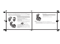
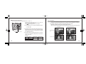
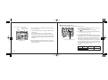
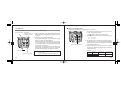
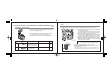
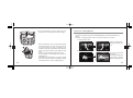
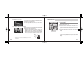
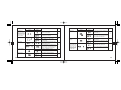
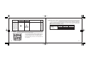
Thank you for purchasing the OLYMPUS Electronic Flash (FL-36). Before use, please read this instruction manual to ensure your
safety, and keep it handy for future reference.
SAFETY PRECAUTIONS (Be sure to read and observe the following.)
This instruction manual uses a variety of common symbols and icons to assist you in proper handling and usage of this product
properly, and to warn you of potential hazards to yourself and others as well as to property. These symbols and their significance
are described below.
DANGER
Failure to observe the
precautions indicated by this
symbol may result in serious
injury or death.
WARNING
Failure to observe the
precautions indicated by this
symbol may result in injury
or death.
Symbols for prohibiting action
Prohibited
Disassembly
prohibited
CAUTION
Failure to observe the
precautions indicated by this
symbol may result in injury or
property damage.
Symbol instructing action
Mandatory
For customers in Europe
The “CE” mark indicates that this product complies with the European requirements for safety, health, environment
and customer protection. CE-mark products are for sale in Europe.
For customers in USA
FCC Notice
This device complies with part 15 of the FCC rules. Operation is subject to the following two conditions:(1) This device may not
cause harmful interference, and (2) this device must accept any interference received, including interference that may cause
undesired operation.
Any unauthorized changes or modifications to this equipment would void the user’s authority to operate.
For customers in CANADA
This Class B digital apparatus complies with Canadian ICES-003.
2
This electronic flash has been designed exclusively for use with Olympus digital cameras. Do not connect the electronic flash
to a camera not manufactured by Olympus, as this may result in a malfunction or damage to the camera and/or flash.
DANGER
The electronic flash incorporates high-voltage circuitry. Never attempt to disassemble or modify it, as this may
result in electric shock and/or injury.
Do not use the electronic flash in a place where it may be exposed to flammable or explosive gas. Otherwise, fire
ignition or explosion may result.
To prevent a traffic accident, do not direct the flash towards the driver of a car.
WARNING
Do not fire the flash or AF illuminator light immediately in front of a person’s eyes (particularly an infant). Exposure
to the light from the flash at a very short range may cause irreparable injury to the eyes. Be especially careful to
avoid using the electronic flash at a distance of less than 1 meter from an infant.
Do not leave the electronic flash and batteries within reach of children.
• If a child swallows a battery or small accessory, see a doctor immediately.
• If the flash is emitted near a child, their eyes may be injured irreparably.
• Moving parts of the electronic flash could injure a child.
Avoid the following actions to prevent fire or injury due to battery fluid leak, overheating, fire ignition or bursting.
• Do not use batteries that are not specified for use with this electronic flash.
• Do not throw the battery in a fire, expose it to heat, short-circuit it, or disassemble it.
• Do not mix old and new batteries, or batteries of different types or brands.
• Do not attempt to recharge non-rechargeable batteries such as alkaline batteries.
• Do not load batteries with the +/– polarity reversed.
Do not store the electronic flash in a place exposed to excessive dust or moisture. Otherwise, fire or electric shock
may result.
Do not use the flash when it is covered by a flammable object such as a handkerchief.
Do not touch the light-emitting area after use. It will be very hot and could burn you.
If the electronic flash is dropped in water or any fluid gets inside, immediately remove the batteries and contact
your dealer or Olympus. Continued use could result in fire or electric shock.
3
CAUTION
If you notice any abnormalities such as leakage, discoloration, deformation, overheating, or odor, stop using this device. Continued use could result in fire, overheating or explosion. Remove the batteries carefully to avoid burning
yourself and to prevent exposure to gas or dangerous fluids that may be released. For repair, contact Olympus.
Always remove the batteries when you don’t expect to use the electronic flash for a long period. Otherwise, heat
generation or fluid leak from the batteries may result in fire, injury and/or contamination of the surroundings.
Do not touch the electric contacts of the electronic flash to prevent malfunction.
To prevent overheating and deterioration of the light-emitting section, do not continue full activation more than 10
times in a row. After 10 successive operations, stop firing for a while until the light-emitting section cools down.
BATTERY PRECAUTIONS
Do not use a leaking battery. Doing so could result in fire or electric shock. Please contact your dealer or Olympus.
Use only the specified batteries. (see page 14)
Do not handle the electronic flash with wet hands. Doing so could result in electric shock.
■ Be sure to observe the following points. Otherwise, battery fluid leak, overheating, fire ignition and/or bursting may
result.
• Do not mix old and new batteries, recharged and discharged batteries, batteries of different capacities, or
batteries of different types or brands.
• Do not attempt to recharge non-rechargeable batteries such as alkaline batteries.
• Do not load or use the batteries with the +/– polarity reversed. If the batteries do not fit smoothly in the battery
compartment, do not force them.
• Never use a battery if its outer coating (insulation) has been partially or entirely peeled off. Otherwise, leakage,
overheating or explosion may result.
• Some brand-new batteries may also have their outer coating (insulation) peeled off completely or partially.
Never use these batteries.
Do not leave the electronic flash in a place where it may be exposed to high temperatures. Otherwise, deterioration
of parts or fire may result.
Do not take out the batteries immediately after using the electronic flash continuously for a long period.
Otherwise, the hot batteries may cause burns.
Do not deform the battery compartment or allow any foreign objects to get inside.
HANDLING PRECAUTIONS
The electronic flash is composed of precision electronic parts. Absolutely avoid using or storing the electronic flash
in the following places, as this may result in malfunction or failure.
• Under direct sunlight, on a beach, etc.
• Anywhere exposed to high temperatures and humidity or rapid fluctuations in temperature and humidity.
• Any place exposed to excessive sand, dust or dirt.
• Near a fire.
• Near an air conditioner or air humidifier.
• Any place exposed to water or moisture.
• Any place subject to vibrations.
• Inside an automobile.
■ Do not use the following kinds of batteries.
Do not apply a strong vibration or shock to the electronic flash by dropping it or hitting it against something.
■ All rechargeable batteries must be recharged using the specified battery charger, simultaneously and completely.
Be sure to read the battery and battery charger instruction manual.
When the electronic flash has not been used for a long period, mold or moss may form. This can cause a
malfunction. To prevent this, it is recommended to check the operations before using the electronic flash after a
long period of storage.
4
Outer coating (insulation) is peeling or
has peeled off (even
if the battery is brandnew).
The negative end is
slightly swollen and
is not covered by the
coating (insulation).
The negative end is
flat (whether or not a
part of the negative
pole is covered by
the coating).
5
■ Improper use of batteries may result in fluid leak, heat generation and/or damage. Sweat and oil smudges may
cause battery contact failure. To prevent this, remove any stain completely with a dry cloth and insert the batteries
by observing the +/– polarity.
■ In general, battery performance will be temporarily reduced as the ambient temperature drops. When using batteries in a cold place, keep them warm by keeping the electronic flash in cold protection gear or clothing.
■ If battery fluid gets on your skin or clothes, it may irritate your skin. Immediately rinse your skin or clothes with clean
water.
■ If battery fluid comes in contact with your eyes, blindness may result. Rinse your eyes with clean water without
rubbing them and see a doctor immediately.
■ Do not apply a strong shock to a battery or throw it.
■ When traveling, it is a good idea to carry spare batteries with you. In some countries, it may be difficult to obtain
certain batteries.
■ Do not immerse batteries in water or expose to moisture including rain, seawater and animal urine.
■ If the +/– terminals of a battery are stained with sweat or oil smudges, contact failure may result. Clean the terminals well with a dry cloth before using the batteries.
■ Do not throw a battery in fire or heat it.
Note on the cameras used with the Electronic Flash
● The functions available from the electronic flash are limited with certain digital cameras. For details, please check the
Olympus website (http://www.olympusamerica.com/E1).
Before reading this manual
○ The information in this manual may be subject to change without notice.
○ This manual has been compiled as carefully as possible. However, if you have any questions or wish to report an error
or omission, please contact Olympus.
○ Duplication of this manual in part or in whole without permission of Olympus is prohibited except for personal use.
Reproduction of the contents of this manual without permission of Olympus is strictly prohibited.
○ Olympus will not assume any liability for the damages, loss of profit or claims from any third party incurred due to
improper use of this product.
○ Olympus will not assume any liability for the damages and loss of profit related to the loss of image data due to a failure
of this product, servicing by a third party not designated by Olympus or any other reason.
○ Note that the quality of the pictures shot using this product differs from that of the pictures of ordinary film-based
cameras.
Trademark information
All brand names and product names mentioned in this manual are the trademarks or registered trademarks of their respective owners.
■ When disposing of batteries, be sure to follow local regulations.
■ When disposing of a rechargeable battery, insulate the +/– terminals with pieces of tape and take them to your
nearest rechargeable battery recycling center.
6
7
CHECKING THE PACKAGE CONTENTS
CONTENTS
•
Selecting the control mode ................ 34
AUTO ................................................. 35
MANUAL ............................................ 37
Checking the Package Contents .................. 9
Nomenclature ............................................. 10
• Control Panel Indicators ............................. 12
• Loading Batteries ....................................... 14
•
•
Checking Batteries ..................................... 16
• Attaching to the Camera/Removing from
the Camera ................................................ 18
•
•
Picture Shooting Using a Digital Camera
with Communication Capability ................. 20
Selecting the control mode .................. 20
TTL AUTO ........................................... 22
AUTO .................................................. 24
MANUAL ............................................. 27
FP TTL AUTO ...................................... 29
FP MANUAL ........................................ 32
• Picture Shooting Using a Digital Camera
Check that all parts and accessories are present.
If any item is missing or damaged, contact your dealer.
Other Operations ....................................... 39
Bounce Shooting ............................... 39
Close-up Flash ................................... 41
Manual Switching of Firing angle (ZOOM) .................. 42
Using the Wide Panel ........................ 43
Various Flash Shooting Methods ....... 45
Custom Setup ............................................ 47
All Reset ..................................................... 50
• Continuous Firing ....................................... 51
•
•
Guide Number (GN) List ............................ 52
• Warning Display List .................................. 55
• Q&A ........................................................... 58
•
•
• Electronic flash, main body
• Flash case
• Batteries must be purchased separately.
Main Specifications .................................... 61
without Communication Capability ............ 34
8
9
NOMENCLATURE
Bounce lock release button
(left-right direction)(Page 40)
Wide panel (Page 43)
AF illuminator light-emitting area
When the subject is dark or lowcontrast, the built-in AF illuminator
emits light to facilitate focusing.
The AF illuminator can also be
defeated. (Page 47)
• The AF illuminator only works
with the Olympus Four Thirds
System digital SLR camera. It
does not work with other cameras.
Accessory shoe
Bounce up/down angle indices
(Page 40)
Bounce left/right angle indices
(Page 40)
AUTO CHECK lamp
(Page 22)
Light-emitting
area
Auto light receptor
Lock pin (Page 18)
Bounce lock release button
(up-down direction)(Page 40)
Control panel (Page 12)
Charge lamp/Test button
(Page 16)
MODE button
(Pages 21 & 34)
Battery compartment cover
(Page 15)
LIGHT button
Press to light up the control
panel for about 15 sec.
The panel also lights under
control by a digital camera with
communication capability.
Select dial (Page 23)
Lock ring (Page 18)
Electric contact
(Page 18)
10
ZOOM button (Page 42)
Power button
11
CONTROL PANEL INDICATORS
FP emission
(Pages 29 & 32)
Control mode
(Pages 20 & 34)
Light intensity adjustment
(Pages 23, 26, 28, 31 & 33)
FOUR THIRDS
(Page 47)
Wide panel warning
(Page 43)
Zoom mode
(Page 42)
Close-up flash
shooting (Page 41)
Zoom value
(Page 42)
ISO speed
(Page 25)
Lens iris (F)
(Page 47)
Guide Number (GN)
(Pages 52 & 54)
Feet
(Page 47)
Meter
(Page 47)
Setting display
(GN, ISO, F, light control range, optimum shooting
range, and light intensity adjustment value)
Notes on This Manual
• The indications on the control panel may differ from those shown in the illustration above depending on the setup of the electronic flash, the camera in use,
and the shooting conditions.
For example, the firing angle (ZOOM) can be displayed in either of the following
modes.
① FOUR THIRDS : Focal length of a Four Thirds System digital camera
② 135
: Focal length converted to an equivalent angle of view
on a 135 type (35 mm film) camera
The text in this manual employs the FOUR THIRDS display mode and puts value
in the 135 display mode inside parentheses, such as “(XX mm with 135)”. For the
selection of the display modes, see page 47 .
• To simplify explanation, this figure shows the panel with all indicators lit.
12
13
LOADING BATTERIES
How to load the batteries
The batteries are available separately. Always use one of the following battery combinations.
• AA (R6) alkaline batteries (LR6 type) ................................... x 2
• AA (R6) Ni-Cd batteries ....................................................... x 2
• AA (R6) Ni-Mh batteries ....................................................... x 2
• AA (R6) Ni-Mn batteries (ZR6 type) ..................................... x 2
• AA (R6) lithium batteries (FR6 type) .................................... x 2
• AA (R6) oxyride batteries (ZR6Y type) ................................. x 2
• Lithium battery pack (CR-V3 type) (Olympus LB-01) ........... x 1
1. Open the battery compartment cover.
2. Insert the batteries with correct +/– polarity.
3. Close the battery compartment cover.
• The AA (R6) manganese batteries cannot be used.
Recommended Batteries
The flash’s charging circuitry is optimized for use with the following batteries:
• AA (R6) Ni-Mh battery
• Lithium battery pack (CR-V3 type) (Olympus LB-01)
AA (R6) batteries
CR-V3
Notes
• Do not mix old and new batteries or batteries of different types together.
• Remove the batteries when the electronic flash is not going to be used for a long period.
• Carry spare batteries when traveling or when using the flash in cold areas.
14
15
Flash Interval and Flash Count
CHECKING BATTERIES
After loading the batteries, check the remaining battery capacity by turning the electronic flash on.
1. Press the Power button to turn the electronic flash on.
• The control panel lights up and battery charging starts.
2. Ensure that the Charge lamp lights up.
• Replace the batteries if the time taken for the Charge lamp
to light up is longer than the values specified below.
Alkaline or Ni-Mn batteries:
30 sec.
Lithium, Ni-Cd, Oxyride or Ni-Mh batteries: 10 sec.
• If the Charge lamp and AUTO CHECK lamp blink alternately, it means that the battery capacity is running low. In
this case, replace the batteries.
The following table shows the flash intervals and flash counts for various batteries. Data is
based on using batteries all of the same type.
Batteries used
Flash interval
Flash count
AA (R6) alkaline dry cell batteries (LR6 type)
Approx. 7.5 sec.
Approx. 140 times
AA (R6) Ni-Cd batteries (P3SPS type, 1000 mAh)
Approx. 6.5 sec.
Approx. 100 times
AA (R6) Ni-Mh batteries (HHR-3SPS type, 2230 mAh)
Approx. 5.5 sec.
Approx. 200 times
AA (R6) Oxyride batteries (ZR6Y type)
Approx. 6.5 sec.
Approx. 140 times
AA (R6) lithium batteries (FR6 type)
Approx. 7.5 sec.
Approx. 260 times
CR-V3 lithium battery packs (Olympus LB-01)
Approx. 6.5 sec.
Approx. 320 times
• The flash emission interval and count data were obtained from in-house tests at Olympus.
Memo: To perform test flash activation, press the Test button.
3. Press the Power button again to turn the electronic flash off.
16
Turn the electronic flash off in the following cases:
• Before mounting it on the camera or dismounting it from
the camera.
• When flash emission is not required.
• When not using the electronic flash.
17
How to remove
ATTACHING TO THE CAMERA/REMOVING FROM THE CAMERA
Confirm that both the camera and electronic flash are off.
Attaching or removing the electronic flash while either the flash or the camera is on may result in malfunction.
1. Loosen the lock ring completely, then slide the electronic
flash out of the hot shoe.
How to attach
2. Attach the hot shoe cover to the camera.
1. Place the light-emitting section in the standard position
(horizontal, front). If it is in the locked position, press and
turn the Bounce lock release button.
2. Remove the hot shoe cover from the camera.
• Store the hot shoe cover in the pocket located on the inner
side of the flash case.
3. Loosen the lock ring.
• If the lock pin is in the out position, press it in by turning it all
the way in the opposite direction to [←LOCK] until it stops.
Notes
To use the electronic flash with a digital camera not equipped with hot shoe:
Lock pin
Electric contact
• If the camera has an external flash terminal, the electronic flash can be attached and connected using the flash
bracket and bracket cable (optional).
• The electronic flash cannot be used with a camera that is not equipped with a hot shoe or external flash terminal.
• Do not apply excessive force to the lock pin.
• Do not touch the electric contact with a finger or metallic object.
• Do not attach the electronic flash while the lock pin is in the out position.
Otherwise, malfunction may result.
4. Slide the electronic flash all the way into the hot shoe until
it stops with a click.
5. Turn the lock ring all the way into the direction of
18
until it stops.
[←LOCK]
19
PICTURE SHOOTING USING A DIGITAL CAMERA WITH COMMUNICATION CAPABILITY
Flash control
mode
<Selecting the control mode>
1. Turn the camera on.
2. Turn the electronic flash on. The batteries are recharged
when the Charge lamp lights up.
TTL AUTO
AUTO
3. Press the Shutter button of the camera gently to start communication of shooting information including ISO speed,
lens iris and shutter speed between the camera and electronic flash.
4. Press the MODE button of the electronic flash to select
Flash
control mode
20
the flash control mode.
• The selected flash control mode is shown in the control
panel.
• The mode is switched every time the MODE button is
pressed.
MANUAL
FP
TTL AUTO
FP
MANUAL
Control panel
display
Control operation
Main application
Ref.
Pages
Flash is controlled automatically
by performing pre-flash according to the camera setup.
Usually use this mode with a
camera with communication
capability.
22
Flash light intensity is controlled
according to the light detected
through the auto light receptor of
the flash and to the camera setup.
If the camera has communication capability, this mode can be
used only when the camera is
an AUTO-compatible model.
24
Flash is performed according to
the manually set guide number
(GN).
Shooting using manual flash.
TTL AUTO and MANUAL modes
with Super FP emission that can
synchronize with the high-speed
shooting of the single-lens-reflex
focal plane shutter.
Outdoor shooting using flash,
such as sync shooting in the
daytime.
27
29 & 32
Notes
• Certain modes may be unavailable depending on the shooting mode set on the camera and the functions of the
camera in use.
• It is not possible to select an unavailable mode.
21
Light intensity adjustment
<TTL AUTO>
The flash light intensity can be adjusted between +3 and –3.
In this mode, pre-flash is performed to measure the optimum flash intensity and then actual flash is
performed.
TTL AUTO indicator
ZOOM indicator
Displayed according to the
focal length of the lens.
The light intensity adjustment must be set to ON in the
custom setup operation (page 47).
• The
indicator appears in the control panel.
1. The control panel shows the light control range according
1. Turn the select dial to choose a light intensity adjustment value.
to the camera setup.
0 → +0.3 → +0.7→ +1.0 ... +3.0
0 → –0.3 → –0.7→ –1.0 ... –3.0
2. Confirm that the distance to the subject is within the light
control range.
If not, adjust the lens iris (F) or the subject distance.
The light control range varies according to the camera type
and camera setup (ISO speed, lens iris (F) and lens focal
distance (ZOOM)).
Light control range
3. When flash activation has been performed correctly, the
AUTO CHECK lamp blinks for about 5 seconds after the
shutter is released.
2. The display shows the light intensity adjustment value except when the value is 0. In this case, the displayed light
control range corresponds to an adjustment value of 0.
3. If the camera’s flash adjustment mode is selected, the
Light intensity adjustment value
actual flash light intensity will be the total of the light
intensity adjustment value set on the FL-36 and that
set on the camera. The light intensity adjustment value
displayed is that of the FL-36 only.
[Example]
Selected
Adjustment value
Actual light intensity
adjustment value displayed on FL-36 adjustment
22
FL-36
+0.3
Camera
+0.3
+0.3
+0.6
23
`çãÄáå~íáçåë=çÑ=fpl=ëéÉÉÇë=~åÇ=äÉåë=áêáëÉë
Åçåíêçää~ÄäÉ=áå=^rql=ãçÇÉ
<AUTO>
In this mode, the flash light intensity is controlled automatically according to the lens iris (F) setting and
the amount of light input to the auto light receptor.
AUTO indicator
ZOOM indicator
Displayed according to the
focal distance of the lens.
1. The control panel shows the light control range according
24
control range.
If not, adjust the lens iris (F) or the subject distance.
The light control range varies according to the camera
setup (ISO speed, lens iris (F) and lens focal length
(ZOOM)).
Lens iris
to the camera setup.
The light control range is not displayed if the camera setup
(ISO speed and lens iris (F)) does not match one of the
usable ISO speed/lens iris (F) combinations.
In this case, the ISO and F indicators blink to alert you.
Change the camera setup (ISO speed and/or lens iris (F)).
(See page 55.)
2. Confirm that the distance to the subject is within the light
Light control range
ISO speed
3200
1600
800
400
200
100
F8
F5.6
F4
F2.8
F2
F1.4
50
25
F11
F8
F5.6
F4
F2.8
F2
F1.4
F16
F11
F8
F5.6
F4
F2.8
F2
F22
F16
F11
F8
F5.6
F4
F2.8
F2
F32
F22
F16
F11
F8
F5.6
F4
F2.8
F32
F22
F16
F11
F8
F5.6
F4
F32
F22
F16
F11
F8
F5.6
F32
F22
F16
F11
F8
F32
F22
F16
F11
F1.4
3. When flash activation has been performed correctly, the
AUTO CHECK lamp blinks for about 5 seconds after the
shutter is released.
Memo: Test flash activation
Flash activation can be tested before actually releasing the shutter.
Press the Test button for test flash activation.
The light control is OK when the AUTO CHECK lamp blinks for about 5 seconds
after the test flash activation.
If the lamp does not blink, change the lens iris (F), ISO speed, subject distance, etc.
• The light check by means of test flash activation is possible only in the AUTO mode.
25
Light intensity adjustment
<MANUAL>
The flash light intensity can be adjusted between +3 and –3.
The light intensity adjustment must be set to ON in the
custom setup operation (page 47).
• The
indicator appears in the control panel.
In this mode, the flash is emitted according to the guide number (GN) setting.
MANUAL indicator
1. Turn the select dial to choose a light intensity adjustment value.
ZOOM indicator
Displayed according to the
focal distance of the lens.
0 → +0.3 → +0.7→ +1.0 ... +3.0
0 → –0.3 → –0.7→ –1.0 ... –3.0
Set the guide number (GN) so that the optimum shooting
distance is equal to the subject distance.
When the optimum shooting distance is 0.6 m (0.5 m in
case of close-up flash) or less, the displayed figure blinks
to warn that the subject is located outside the flash light
emission area.
Optimum shooting distance varies according to the camera settings (ISO speed, lens iris (F) and lens focal distance (ZOOM)). See page 52 for details.
cept when the value is 0. In this case, the displayed light
control range corresponds to an adjustment value of 0.
3. If the camera’s flash adjustment mode is selected, the
actual flash light intensity will be the total of the light
intensity adjustment value set on the FL-36 and that
set on the camera. The light intensity adjustment value
displayed is that of the FL-36 only.
[Example]
Guide number (GN)
Selected
Adjustment value
Actual light intensity
adjustment value displayed on FL-36 adjustment
26
FL-36
+0.3
Camera
+0.3
+0.3
+0.6
together with the optimum shooting distance according to
the camera setup.
2. Turn the select dial to set the guide number (GN).
2. The display shows the light intensity adjustment value ex-
Light intensity adjustment value
1. The control panel shows the current guide number (GN)
Optimum shooting
distance
Memo: Assuming that the ISO speed is 100, the optimum shooting distance can be calculated with the following formula.
Optimum shooting distance = Guide number (GN)/Lens iris (F)
(See page 54.)
27
Light intensity adjustment
<FP TTL AUTO>
The flash light intensity can be adjusted between +0.7 and –0.7.
The light intensity adjustment must be set to ON in the
custom setup operation (page 47).
• The
indicator appears in the control panel.
1. Turn the select dial to choose a light intensity adjustment value.
• In this mode, the flash uses Super FP emission to synchronize with high shutter speeds.
• For details on using the camera’s built-in flash, see “Various Flash Shooting Methods” on page 45.
The following operations are possible at high shutter speeds in this mode.
• Attenuation of shades when shooting a picture against the light.
• Outdoor portrait shooting using daytime sync shooting with the lens iris opened up to blur the background.
0 → +0.3 → +0.7
0 → –0.3 → –0.7
Without flash
With flash (FP TTL AUTO)
With lens iris adjusted
With lens iris open
2. The display shows the light intensity adjustment value ex-
Light intensity adjustment value
cept when the value is 0. In this case, the displayed guide
number (GN) and optimum shooting distance correspond
to an adjustment value of 0.
Shooting against
light
3. Even if the camera’s flash adjustment mode is selected,
only the FL-36’s adjustment setting will work. The camera’s
setting will not work.
[Example]
Selected
Adjustment value
Actual light intensity
adjustment value displayed on FL-36 adjustment
28
FL-36
+0.3
Camera
+0.3
+0.3
Portrait shooting
+0.3
29
Light intensity adjustment
The flash light intensity can be adjusted between +3 and –3.
FP TTL AUTO indicator
ZOOM indicator
Displayed according to the
focal length of the lens.
1. The control panel shows the light control range according
The light intensity adjustment must be set to ON in the
custom setup operation (page 47).
• The
indicator appears in the control panel.
to the camera setup.
2. Confirm that the distance to the subject is within the light
1. Turn the select dial to choose a light intensity adjustment value.
control range.
If not, adjust the lens iris (F) or the subject distance.
The light control range varies according to the camera
setup (ISO speed, lens iris (F) and lens focal distance
(ZOOM). The light control range is smaller than that in the
TTL mode.
Light control range
3. When flash activation has been performed correctly, the
AUTO CHECK lamp blinks for about 5 seconds after the
shutter is released.
0 → +0.3 → +0.7→ +1.0 ... +3.0
0 → –0.3 → –0.7→ –1.0 ... –3.0
2. The display shows the light intensity adjustment value except when the value is 0. In this case, the displayed light
control range corresponds to an adjustment value of 0.
Light intensity adjustment value
3. If the camera’s flash adjustment mode is selected, the
actual flash light intensity will be the total of the light
intensity adjustment value set on the FL-36 and that
set on the camera. The light intensity adjustment value
displayed is that of the FL-36 only.
[Example]
Selected
Adjustment value
Actual light intensity
adjustment value displayed on FL-36 adjustment
30
FL-36
+0.3
Camera
+0.3
+0.3
+0.6
31
Light intensity adjustment
<FP MANUAL>
The flash light intensity can be adjusted between +0.7 and –0.7.
In this mode, Super FP emission is performed at the set light intensity.
FP MANUAL indicator ZOOM indicator
Displayed according to the
focal distance of the lens.
The light intensity adjustment must be set to ON in the
custom setup operation (page 47).
• The
indicator appears in the control panel.
1. Turn the select dial to set the guide number (GN). Together
with the optimum shooting distance according to the camera setup.
1. Turn the select dial to choose a light intensity adjustment value.
2. Turn dial A to set the guide number (GN).
Set the guide number (GN) so that the optimum shooting
distance is equal to the subject distance.
When the optimum shooting distance is 0.6 m (0.5 m in
case of close-up flash) or less, the displayed figure blinks
to warn that the subject is located outside the flash light
emission area. (see page 55.)
The optimum shooting distance varies according to the
camera setup (ISO speed, lens iris (F), lens focal length
(ZOOM) and shutter speed). See page 54 for details.
Guide number (GN)
Optimum shooting distance
32
0 → +0.3 → +0.7
0 → –0.3 → –0.7
2. The display shows the light intensity adjustment value exLight intensity adjustment value
cept when the value is 0. In this case, the displayed guide
number (GN) and optimum shooting distance correspond
to an adjustment value of 0.
3. Even if the camera’s flash adjustment mode is selected,
only the FL-36’s adjustment setting will work. The camera’s
setting will not work.
[Example]
Memo: The optimum shooting distance can be calculated with the
following formula.
Optimum shooting distance = Guide number (GN)/Lens iris (F)
Selected
Adjustment value
Actual light intensity
adjustment value displayed on FL-36 adjustment
FL-36
+0.3
Camera
+0.3
+0.3
+0.3
33
PICTURE SHOOTING USING A DIGITAL CAMERA WITHOUT COMMUNICATION CAPABILITY
<AUTO>
In this mode, the flash light intensity is controlled automatically according to the lens iris (F) setting.
<Selecting the control mode>
ISO speed
AUTO indicator MZOOM indicator
1. Turn the electronic flash on. The batteries are recharged
1. Adjust Zoom according to the focal length of the lens.
2. While keeping the MODE button pressed, turn the select dial within
2 seconds to set the ISO speed.
Note: If the MODE button is kept pressed for more than 2 seconds,
the flash mode changes to the Custom Setup mode (see page 47).
3. Turn the select dial according to the lens iris (F).
If the camera setup (ISO speed and lens iris (F)) does not
match one of the usable ISO speed/lens iris (F) combinations, the ISO and F indicators blink to alert you. In this case,
change the camera setup (ISO speed and/or lens iris (F)).
4. When flash activation has been performed correctly,
the AUTO CHECK lamp blinks for about 5 seconds
after the shutter is released.
when the Charge lamp lights up.
2. Press the MODE button to select the flash control mode.
• The selected mode is shown in the control panel.
• The mode is switched every time the MODE button is
pressed.
Lens iris (F)
Flash control
mode
AUTO
MANUAL
34
Control panel
display
Control operation
Main application
Flash light intensity is controlled
according to the light detected
through the auto light receptor of
the flash and to the lens iris (F).
Usually use this mode.
Flash activation is performed
according to the manually set
guide number (GN).
Shooting using manual flash.
Ref.
Pages
Memo: By selecting an ISO speed and lens iris (F) different from those
set on the camera, the light intensity can be adjusted in 1/3 steps.
Memo: Test flash activation
35
37
Flash activation can be tested before actually releasing the shutter.
Press the Test button for test flash activation.
The light control is OK when the AUTO CHECK lamp blinks for about 5 seconds after
the test flash activation.
If the lamp does not blink, change the lens iris (F), ISO speed, subject distance, etc.
• The light check by means of test flash activation is possible only in the AUTO mode.
35
<MANUAL>
Light control range in AUTO mode
Firing angle (mm)
ISO speed
8 (W panel) 10 (W panel)
3200 1600 800 400 200 100 50 25 16 (W panel) 20 (W panel)
F8 F5.6 F4
F11 F8
F2.8 F2
F5.6 F4
F16 F11 F8
F5.6 F4
Lens iris
F22 F16 F11 F8
F1.4
F2.8 F2
F32 F22 F16 F11 F8
F1.4
F2.8 F2
F5.6 F4
F1.4
F2.8 F2
F5.6 F4
F32 F22 F16 F11 F8
AUTO light control range (m)
F2.8
F5.6 F4
F32 F22 F16 F11 F8
F5.6
F32 F22 F16 F11 F8
F32 F22 F16 F11
Guide number (GN) MANUAL indicator
Upper row: FOUR THIRDS. Lower row: 135
12
14
17
25
35
1. The control panel shows the current guide number (GN).
42
24
28
35
50
70
85
0.8 - 8.6
0.9 - 10.0
1.3 - 14.3
1.4 - 15.7
1.5 - 17.1
1.8 - 20.0
2.0 - 22.9
2.3 - 25.7
0.6 - 6.0
0.6 - 7.0
0.9 - 10.0
1.0 - 11.0
1.1 - 12.0
1.3 - 14.0
1.4 - 16.0
1.6 - 18.0
0.5 - 4.3
0.5 - 5.0
0.6 - 7.1
0.7 - 7.9
0.8 - 8.6
0.9 - 10.0
1.0 - 11.4
1.1 - 12.9
0.5 - 3.0
0.5 - 3.5
0.5 - 5.0
0.5 - 5.5
0.5 - 6.0
0.6 - 7.0
0.7 - 8.0
0.8 - 9.0
0.5 - 2.1
0.5 - 2.5
0.5 - 3.6
0.5 - 3.9
0.5 - 4.3
0.5 - 5.0
0.5 - 5.7
0.6 - 6.4
0.5 - 1.5
0.5 - 1.8
0.5 - 2.5
0.5 - 2.8
0.5 - 3.0
0.5 - 3.5
0.5 - 4.0
0.5 - 4.5
0.5 - 1.1
0.5 - 1.3
0.5 - 1.8
0.5 - 2.0
0.5 - 2.2
0.5 - 2.5
0.5 - 2.9
0.5 - 3.3
0.5 - 0.8
0.5 - 0.9
0.5 - 1.3
0.5 - 1.4
0.5 - 1.5
0.5 - 1.8
0.5 - 2.0
0.5 - 2.3
0.5 - 0.5
0.5 - 0.6
0.5 - 0.9
0.5 - 1.0
0.5 - 1.1
0.5 - 1.3
0.5 - 1.5
0.5 - 1.6
The above table shows the light control ranges in the off-flash condition.
The displayed nearer value is 0.6 or more when the light emission section faces the front and 0.5
or more when it faces downward.
36
In this mode, the flash is emitted according to the guide number (GN) setting.
2.
Adjust the MZOOM indicator according to the focal length
of the lens.
3. Turn the select dial to set the guide number (GN).
MZOOM indicator
Light intensity ratio
In the Custom Setup mode, the flash intensity can be displayed in a light intensity ratio instead of the guide number
(see page 49).
Light intensity ratio: Ratio of emitted light intensity with
respect to the intensity at full emission.
37
How to determine the lens iris (F), guide number (GN) and shooting distance
1. When the shooting distance and lens iris are already determined:
OTHER OPERATIONS
Bounce Shooting
Determine the guide number (GN) with the following formula and set the GN on the FL-36.
Bounce shooting refers to a method in which the light from the flash is bounced off the ceiling or walls.
This allows the light to go all around the subject, resulting in a soft picture without harsh contrast
or shadow.
Lens iris (F) x Shooting distance (m)
Guide number (GN) =
ISO speed coefficient
Shooting without bounce
2. When it is necessary to determine the lens iris (F):
Bounce shooting
Determine the lens iris (F) with the following formula and set F on the FL-36.
Lens iris (F) =
Guide number (GN) x ISO speed coefficient
Shooting distance (m)
3. When it is necessary to determine the optimum shooting distance:
Optimum shooting=
distance (m)
Guide number (GN) x ISO speed coefficient
Lens iris (F)
ISO speeds and their coefficients
ISO speed
25
50
100
200
400
800
1600
3200
Coefficient
0.5
0.71
1.0
1.4
2.0
2.8
4.0
5.6
See page 52 for the guide number list.
38
39
Operation
Close-up Flash
1. While holding the Bounce lock release button, revolve the
90˚
180˚
7˚
90˚
Bounce lock release button
(up-down direction)
Bounce lock release button
(left-right direction)
light-emitting section in the up-down and left-right directions.
The light-emitting section can be revolved in the range
shown in the figure on the left.
1. While keeping the Bounce lock button pressed, tilt the flash
down (7°)
2. The close-up flash indicator lights in the control panel.
Down: 7°
(See “Close-up Flash” on page 41.)
If the position of the light-emitting section is locked, press
and hold the Bounce lock release button and then change
the position.
• The light control range and optimum shooting distance are not displayed in the control panel.
• The color of the surface (ceiling and/or walls) off which the light is bounced will affect the
pictures you take. Whenever possible, bounce the light off a neutral surface.
• When the firing angle adjustment is automatic (ZOOM), the ZOOM display on the control
panel shows “- -” and the firing angle is set to 25 mm (50 mm with 135 type).
• When the firing angle adjustment is based on manual switching (M ZOOM), the firing angle
can be varied manually (see page 42).
40
The flash activation area is inaccurate when the subject distance is between 0.5 and 1.0 m. In this case,
tilt the flash down.
Close-up flash indicator
(0.5∼1.0m)
Available shooting range
• The recommended range for this flash is 0.5 to 1.0 m.
• The available shooting range is displayed on the control panel. The maximum shooting distance is 2.5 m.
• The flash light may be blocked when the lens is long or large in diameter. Be sure to perform test shooting.
• Do not tilt the flash down in normal shooting. This will darken the upper part of the image.
41
Manual Switching of Firing angle (ZOOM)
Using the Wide Panel
The firing angle can be adjusted manually.
Use the built-in wide panel in flash shooting when the lens focal length is set to a wider position than 12 mm.
MZOOM indicator
1. Press the ZOOM button to adjust the firing angle.
• The M ZOOM indicator lights in the control panel.
• The firing angle can be set to one of 12, 14, 17, 25, 35 and
42 mm (24, 28, 35, 50, 70 and 85 mm with 135 type).
Each press of the ZOOM button switches the firing angle as
follows.
• The ZOOM indicator lights in AUTO ZOOM mode.
AUTO
ZOOM
12
(24)
14
(28)
17
(35)
25
(50)
35
(70)
1. When the lens focal length is shorter than 12 mm (24 mm
with the 135 type), the wide panel warming indicator lights
in the control panel.
(This does not occur if the camera is not equipped with
communication capability.)
42
(85)
When the wide panel is used: (see page 43)
AUTO
ZOOM
10
(20)
8
(16)
2. Slide out the wide panel and place it on the light-emitting area.
• The wide panel indicator lights in the control panel.
• AUTO ZOOM can be selected only when the camera in
use is equipped with the communication capability.
Note
Selecting a ZOOM value larger than your lens’s focal length will darken
the peripheral areas of the image.
42
43
Wide panel indicator
3. Press the ZOOM button to select the firing angle from 8
Various Flash Shooting Methods
mm and 10 mm (16 mm and 20 mm with the 135 type).
The following flash shooting methods are possible according to the camera setup.
• Some flash shooting methods may be unavailable depending on the function and design of the
camera.
• For details on operating procedure, refer to the instruction manual for your camera.
1. Red eye-reduction flash
• When the wide panel is used, the actual guide number
(GN) will be lower than set. In the TTL AUTO, AUTO and
FP TTL AUTO modes, this results in a reduction of the
available shooting range. In the MANUAL and FP MANUAL
modes, this results in a reduction of the optimum shooting
range.
• Be sure to store the wide panel again after shooting.
• To prevent damage to the wide panel, do not flip it in the
upward direction.
• If the wide panel is damaged when it is slid out, the ZOOM
button will no longer be operable. If that happens, disable
the wide panel switch to restore operability (page 47).
44
Reduces the appearance of
red eyes due to flash emission.
2. Slow sync
The flash is emitted with
slow shutter.
This makes it possible to take
clear pictures of subjects
against a night background.
45
3. Background screen sync
CUSTOM SETUP
Slow shutter is used and the flash is emitted immediately
before the end of exposure period.
This makes it possible to take pictures of moving objects
such as car taillights with a streaming effect.
Custom setup allows each user to customize flash setup to suit his or her preferences.
Setup procedure
1. Turn the electronic flash on.
4. Combination with camera’s built-in flash
When the camera in use has a built-in flash, it can be used
simultaneously with the electronic flash.
• Advanced shooting techniques are possible. For example, you
can bounce the light from the electronic flash off the wall or ceiling while using the camera’s built-in flash for a catch-light effect.
• With certain camera models, the built-in flash may be disabled
when the electronic flash is mounted on the camera’s hot shoe.
2. Press and hold the MODE button for more than 2 seconds, until the setup mode display appears in the control
panel.
3. Press the MODE button momentarily to select the setup
mode.
4. TTurn the select dial to select the value.
5. Keep the MODE button pressed for more than 2 seconds
Note
to exit from setup and return to the previous control panel
display.
The electronic flash control mode should be set to TTL AUTO or
FP TTL AUTO.
46
47
Setup mode
AF illuminator
Only works with the
Olympus Four Thirds
System digital SLR
camera. It does not work
with other cameras.
Flash cable
Mode display
Value display
Dial A
Dial B
Function
Default
Wide panel
switch disabling
AF illuminator is activated according to the
control from the camera.
A
Use this setting when not using the flash
cable (clipping on to the hot shoe).
on
Distance display
unit
Value display
Dial A
Dial B
Function
GN (guide number)
indicator
Default
The wide panel switch is activated. Use
this setting to detect that the wide panel
has been slid out.
on
The flash intensity is displayed in a GN
(guide number).
on
The flash intensity is displayed in a light
intensity ratio.
Firing angle (ZOOM) is displayed in terms
of the lens focal length of a FOUR
THIRDS digital camera.
Firing angle (ZOOM) is converted into the focal distance of the 135 type. This allows the
flash to be used in the same feeling as the
flash for a 135 type (35 mm film) camera.
Mode display
The wide panel switch is deactivated. Use
this setting when the wide panel is damaged so that the firing angle can be
changed with the ZOOM button.
AF illuminator is defeated.
Use this setting when using the flash cable
(off flash cable).
Firing angle
(ZOOM) display
Setup mode
4-3
Distance is displayed in meters.
ISO and F communication in AUTO mode
Only works with a
camera with ISO
speed setting communication capability
in AUTO mode.
The ISO speed and lens iris (F) are automatically set by the camera side.
on
The ISO speed and lens iris (F) can be
set with the select dial.
m
Distance is displayed in feet.
Light intensity
adjustment
Light intensity cannot be adjusted.
OFF
Light intensity can be adjusted.
48
49
Setup mode
ISO speed selection in
AUTO mode
Works with a camera without ISO speed setting communication capability in
AUTO mode. Also works
with a camera with ISO
speed setting communication capability in AUTO
mode when the ISO and F
communication in AUTO
mode is set to OFF.
Mode display
Value display
Dial A
Dial B
Function
Default
CONTINUOUS FIRING
Continuous firings make the light-emitting section hot and may cause it to deteriorate or malfunction.
Therefore, continuous firing should be limited to the counts shown in the following table. Always
leave the electronic flash unused for at least 10 minutes after continuous firing up to the limit count.
The ISO speed can be set with the select
dial.
Limit counts of continuous firings
100
Flash control mode
TTL AUTO
AUTO
MANUAL
FP AUTO
FP MANUAL
Light intensity ratio
1/1
1/2
1/4
1/8 to a/128
Flash interval
6 sec.
3 sec.
1 sec.
0.5 sec. or less
Limit count
10
20
40
80
ALL RESET
All Reset resets the custom setups to the factory default settings.
• Press the MODE and LIGHT buttons simultaneously for 2
or more seconds to reset the custom setups (except for
the distance display unit (m/ft)) to the default settings.
• The distance display unit (m/ft) is not altered by the all
reset operation.
50
51
GUIDE NUMBER (GN) LIST
• FP TTL AUTO
• TTL AUTO/AUTO
ZOOM (mm)
TTL AUTO/AUTO
FOUR THIRDS
10
12
14
17
25
35
MANUAL
Light intensity ratio
52
10
12
14
17
25
35
With 135
16
20
24
28
35
50
70
42
85
42
1/125
8.5
9.9
14.1
15.6
17.0
19.8
22.6
25.5
With 135
16
20
24
28
35
50
70
85
1/160
7.5
8.8
12.5
13.8
15.0
17.5
20.0
22.5
Full emission
12
14
20
22
26
28
32
36
1/200
6.7
7.8
11.2
12.3
13.4
15.7
17.9
20.1
1/250
6.0
7.0
10.0
11.0
12.0
14.0
16.0
18.0
1/320
5.3
6.2
8.8
9.7
10.6
12.4
14.1
15.9
1/400
4.7
5.5
7.9
8.7
9.5
11.1
12.6
14.2
1/500
4.2
4.9
7.1
7.8
8.5
9.9
11.3
12.7
1/640
3.8
4.4
6.3
6.9
7.5
8.8
10.0
11.3
1/800
3.4
3.9
5.6
6.1
6.7
7.8
8.9
10.1
1/1000
3.0
3.5
5.0
5.5
6.0
7.0
8.0
9.0
1/1250
2.7
3.1
4.5
4.9
5.4
6.3
7.2
8.0
1/1600
2.4
2.8
4.0
4.3
4.7
5.5
6.3
7.1
1/2000
2.1
2.5
3.5
3.9
4.2
4.9
5.7
6.4
1/2500
1.9
2.2
3.2
3.5
3.8
4.4
5.1
5.7
1/3200
1.7
2.0
2.8
3.1
3.4
3.9
4.5
5.0
1/4000
1.5
1.8
2.5
2.8
3.0
3.5
4.0
4.5
1/5000
1.3
1.6
2.2
2.5
2.7
3.1
3.6
4.0
1/6400
1.2
1.4
2.0
2.2
2.4
2.8
3.2
3.6
1/8000
1.1
1.2
1.8
1.9
2.1
2.5
2.8
3.2
• MANUAL
ZOOM (mm)
8
ISO100, m
8
ISO100, m
FOUR THIRDS
ZOOM (mm)
ISO100, m
FOUR THIRDS
8
10
12
14
17
25
35
42
With 135
16
20
24
28
35
50
70
85
1/1
12.0
14.0
20.0
22.0
24.0
28.0
32.0
36.0
1/2
8.5
9.9
14.1
15.6
17.0
19.8
22.6
25.5
1/4
6.0
7.0
10.0
11.0
12.0
14.0
16.0
18.0
1/8
4.2
4.9
7.1
7.8
8.5
9.9
11.3
12.7
1/16
3.0
3.5
5.0
5.5
6.0
7.0
8.0
9.0
1/32
2.1
2.5
3.5
3.9
4.2
4.9
5.7
6.4
1/64
1.5
1.8
2.5
2.8
3.0
3.5
4.0
4.5
1/128
1.1
1.2
1.8
1.9
2.1
2.5
2.8
3.2
Shutter speed
53
• FP MANUAL
ISO100.m
The following guide number (GN) figures have a 1/1 light intensity ratio.
ZOOM (mm)
Shutter speed
FOUR THIRDS
With 135
1/125
1/160
1/200
1/250
1/320
1/400
1/500
1/640
1/800
1/1000
1/1250
1/1600
1/2000
1/2500
1/3200
1/4000
1/5000
1/6400
1/8000
8
16
8.5
7.5
6.7
6.0
5.3
4.7
4.2
3.8
3.4
3.0
2.7
2.4
2.1
1.9
1.7
1.5
1.3
1.2
1.1
10
20
9.9
8.8
7.8
7.0
6.2
5.5
4.9
4.4
3.9
3.5
3.1
2.8
2.5
2.2
2.0
1.8
1.6
1.4
1.2
12
24
14.1
12.5
11.2
10.0
8.8
7.9
7.1
6.3
5.6
5.0
4.5
4.0
3.5
3.2
2.8
2.5
2.2
2.0
1.8
14
28
15.6
13.8
12.3
11.0
9.7
8.7
7.8
6.9
6.1
5.5
4.9
4.3
3.9
3.5
3.1
2.8
2.5
2.2
1.9
17
35
17.0
15.0
13.4
12.0
10.6
9.5
8.5
7.5
6.7
6.0
5.4
4.7
4.2
3.8
3.4
3.0
2.7
2.4
2.1
25
50
19.8
17.5
15.7
14.0
12.4
11.1
9.9
8.8
7.8
7.0
6.3
5.5
4.9
4.4
3.9
3.5
3.1
2.8
2.5
35
70
22.6
20.0
17.9
16.0
14.1
12.6
11.3
10.0
8.9
8.0
7.2
6.3
5.7
5.1
4.5
4.0
3.6
3.2
2.8
42
85
25.5
22.5
20.1
18.0
15.9
14.2
12.7
11.3
10.1
9.0
8.0
7.1
6.4
5.7
5.0
4.5
4.0
3.6
3.2
The guide numbers (GN) for light intensity ratios other than 1/1 in the FP MANUAL mode can
be calculated with the following formula.
Guide number (GN) = Guide number at 1/1 x Light intensity ratio coefficient
Light intensity ratios and their coefficients
54
Light intensity ratio
1/1
1/2
1/4
1/8
1/16
Coefficient
1.0
0.71
0.5
0.35
0.25
WARNING DISPLAY LIST
• Digital camera with communication capability
Warning details
Control panel display
Remedy
Out of light control
range in AUTO
mode
Change the camera’s ISO speed or lens
iris (F) setting.
Subject too close in
MANUAL mode
①Change the camera’s ISO speed or
lens iris (F) setting.
②Change the guide number (GN) setting.
Subject too close in
FP MANUAL mode
Wide panel
request in all
modes
Ref. Page
P. 24
①Change the camera’s ISO speed or
lens iris (F) setting.
②Change the guide number (GN) setting.
P. 27
P. 32
Set the wide panel.
P. 43
55
• Digital camera without communication capability
Control panel display
Remedy
Ref. Page
Downward
bounce in all
modes
The light-emitting section is set at 7°
downward.
Cancel this setting except for close-up
flash photography.
P. 41
Wide panel warning in all modes
The wide panel is set.
Pay attention to the distance to the subject since a lower guide number (GN) is
selected.
Warning details
Warning details
Downward
bounce in all
modes
Wide panel warning in all modes
P. 43
Out of light control
r a n g e i n AU TO
mode
56
Control panel display
Remedy
Ref. Page
The light-emitting section is set at 7°
downward.
Cancel this setting except for close-up
flash photography.
P. 41
The wide panel is set.
Pay attention to the distance to the subject since a lower guide number (GN) is
selected.
P. 43
Change the camera’s ISO speed or lens
iris (F) setting.
P. 35
57
Q&A
Q Is multi-flash shooting possible in the TTL AUTO mode?
A No, it is not possible.
Q When are test flash activation and auto checking effective?
A Checking the optimum flash activation based on the AUTO CHECK lamp is particularly effective in
bounce flash (in AUTO modes only).
Q What will happen if the electronic flash is activated simultaneously with the camera’s built-in flash?
A In the TTL mode, both flashes emit light simultaneously and the optimum exposure is determined
according to the combined total light intensity (provided that the camera is in the P or A shooting
mode). In bounce flash photography, the camera’s built-in flash can also be used for catch-light
photography (see page 46).
Q Why does the electronic flash get hot after successive firing?
A The batteries generate heat when flash firing is repeated successively. In this case, use the electronic flash at intervals until the flash emission section and batteries cool down.
Q Why can’t I mount the electronic flash on the camera?
A The electronic flash cannot be mounted if the lock pin is in the out position. If this is the case, turn
the lock ring all the way in the opposite direction to [←LOCK] until it stops. Once the lock pin is in
the in position, you can mount the electronic flash on the camera (see page 18).
58
Q Why doesn’t the control mode change when I press the MODE button?
A When the electronic flash is connected to certain types of communication-capable camera, the
flash control mode can only be controlled from the camera.
Q
A
The picture is overexposed. What should I do?
First check the shooting range displayed on the control panel. If your subject is closer than the
displayed shooting range, try one of the following so that the shooting range becomes valid to
your subject.
• Stop down the lens aperture.
• Set the light intensity adjustment value to the negative side (-).
• Use the wide panel.
Q What is the recommended white balance setting for the camera when using the flash?
A The auto white balance mode is recommended. If you use the manual white balance mode, set the
color temperature to 5500K. Note that the color temperature varies depending on the flash shooting conditions.
Q The light control range is not displayed on the control panel. What is wrong?
A The light control range is not displayed in the following cases:
• When the Extension Tube EX-25 (optional) is used
• When the lens is removed
• During bounce photography
• During light intensity adjustment
• When the ISO speed and lens iris (F) are out of the setting range
59
Q When the Olympus E-1 digital camera enters the sleep mode, the FL-36 control panel displays
A
turn off. Is this normal?
Yes, it is normal. When the E-1 enters the sleep mode, the FL-36 does as well. When the camera
wakes up, so does the FL-36.
MAIN SPECIFICATIONS
Model Number
Type
Guide number
Q Does the FL-36 also turn off when the Olympus E-1 digital camera is turned off?
A When the E-1 is turned off, the FL-36 enters the sleep mode. When the E-1 is turned on again, the
FL-36 also turns on. When you want to turn off the FL-36, turn off the FL-36 before turning off the
E-1. In addition, when connected to a camera without communication capability, the FL-36
enters the sleep mode if it is not operated for about 15 minutes.
Firing angle
Flash emission period
Flash emission count
(at full activation)
Recharge time
(from full activation to
charge lamp lighting)
Flash modes
Bounce angles
Auto power OFF
60
: FS-FL36
: External electronic flash for digital still camera
: Automatic switching
36: When in 42 mm (85 mm with 135 type)
20: When in 12 mm (24 mm with 135 type)
8/10 switching: When the wide panel is used.
: Automatic switching.
At 12 mm: Up-down 61°, left-right 78°(equivalent to image angle of 12 mm lens)*
At 42 mm: Up-down 21°, left-right 28°(equivalent to image angle of 42 mm lens)*
When the wide panel is used for 8 mm: Up-down 83°, left-right 101°
(equivalent to image angle of 8 mm lens)*
* ZOOM values are the FOUR THIRDS camera values.
: Approx. 1/20000 to 1/500 sec. (Variable according to the light intensity, except in FP
emission.)
: Approx. 150 times (using the LR6-type AA (R6) alkaline dry cell batteries)
Approx. 320 times (using the LB-01 type lithium battery packs)
(Variable depending on shooting conditions)
: Approx. 7.5 seconds (using the AA (R6) alkaline manganese batteries)
Approx. 6.5 seconds (using the LB-01 type lithium battery packs)
: TTL AUTO, AUTO, MANUAL, FP TTL AUTO, FP MANUAL
: Up 0 to 90°, down 7°, right 0 to 90°, left 0 to 180°
: Interlocks with the auto power OFF operation of a camera with communication capability
61
AF illuminator
Power supply
Dimensions
Weight
Operating environment
: Automatic firing at low intensity, possible only when a camera with communication
capability is connected.
Standard effective distances (Variable depending on the camera and lens in use.)
1 to 5 m (3.3 to 16.4 ft)
: AA (R6) alkaline dry cell batteries (LR6) x 2, AA (R6) Ni-Cd batteries x 2, AA (R6) Ni-Mh
batteries x 2, AA (R6) Ni-Mn batteries (ZR6) x 2, AA (R6) oxyride batteries (ZR6Y type) x 2,
AA (R6) lithium batteries (FR6) x 2 or 3 V lithium battery pack (Olympus LB-01) x 1
: 67(W) x 108(H) x 95(D) mm (2.6 x 4.3 x 3.7 in) (excluding protrusions)
: 210 g (7.4 oz) (excluding batteries)
: Temperature: 0 to 40°C (32 to 104°F)
Humidity: No more than 80% (without condensation)
Specifications are subject to change without any notice or obligation on the part of the manufacturer.
● Technical Support (USA)
24/7 online automated help: http://www.olympusamerica.com/E1
Phone customer : Tel.1-800-260-1625 (Toll-free)
Our phone customer support is available from 8 am to
10 pm (Monday to Friday) ET
E-Mail : [email protected]
● European technical Customer Support
Please visit our homepage http://www.olympus-europa.com
or call NUMBER : Tel.00800-67 10 83 00 (Toll-free)
+49 1805-67 10 83 or +49 40-23 77 38 99 (Charged)
62