1
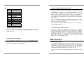
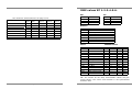
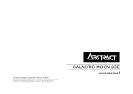
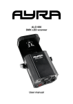
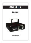
©Abstract AVR Ltd 2004 Tel: +44 (0)116 278 8078
http://www.extreme-dj.com
Abstract Extreme Range Instruction Manual - Issue 1.0: Mar 2004
Written by Sabre Technology (Hull) Ltd http://www.sabretechnology.co.uk
Instruction Manual
Models XP1-XP2-XP3-XP4-XP5-XP6
Page 2
Page 23
Welcome
NOTES
Congratulations on your purchase of this Abstract Extreme
range product. Your new unit offers many exciting features and
can work in harmony with all other products in the Extreme
range to produce an amazing light show.
This booklet contains instructions for the full range of products
and includes important safety information. Please read through
the booklet before operating this product.
“May we take this opportunity to thank you once again for
purchasing this product, if you are new to the Abstract family
we hope you will be completely satisfied with this new and
exiting range of performance DJ lighting effects, if you have
been with our family for some time we wish to thank you for
your continued support and helping us to get to this point in our
development.”
Steve Watts,
M.D.
If you’re in a hurry…
If you don’t want all the details, and you just want to get it
working in a hurry...
Page 22
•
If you are using a DMX controller with the lights, go to
page 10
•
If you are running the lights in sound-to-light mode, go
to page 6
•
If you are in a hurry always adhere to the safety of
operation outlined in this manual. Never enter the unit
with the power cord connected to the Mains supply.
Page 3
What’s where on the unit
Settings for XP 4 (2 Channel)
All the units have the same plugs and indicator lights, though
they are in different positions on the different units. The main
ones are:
1. DMX output socket (pin 3 hot, pin 2 cold, pin 1 screen).
Other DMX devices can be linked in to the system through this
socket. (If you aren’t sure which is which, the output is the
one where you can’t touch the pins.)
2.
DMX input plug (pin 3 hot, pin 2 cold, pin 1 screen). Used to
connect the unit to either a DMX controller or to another unit
in stand-alone mode. You can use a dedicated controller, or a
generic DMX lighting desk. If you are using a controller with a
5-pin DMX output, you will need to use a 5 to 3 pin adaptor.
(Not supplied)
3.
Power on light (red). This light should be on whenever the
unit is powered up. If it doesn’t come on there is either no
power to the unit, a fuse blown in the mains input IEC or some
internal problem with the unit.
4.
DMX present / Audio beat light (green). This light is on
constantly when DMX is being received (it may flicker a bit).
When it is not lit, the unit is in stand-alone mode and the light
will flash when an audio beat is detected.
5.
Dip switches. Dip switches 1-9 set the DMX channel that the
unit will respond to (in binary code) when a DMX controller is
being used. Switch 10 sets the stand alone ‘channel’ of the unit
when in stand-alone mode. See page 20 of this booklet for help
on setting the switches.
6.
Microphone. The unit can sense the beat of the music through
its built-in microphone. The microphone is bass-filtered and will
only pick up low-pitched sounds. Music generated from a source
such as a radio or other small device may not be sufficient to
trigger the sound circuitry to its full potential.
Page 4
Settings for XP 5 and XP 6 (3 Channel)
Dip Switch Conversion Chart:
Top row represents Dipswitch number:
Bottom row represents DMX start address:
Example: Start address 17= 5+1 on. 57= 6+5+4+1 on.
1
2
3
4
5
6
7
8
9
1
2
4
8
16
32
64
128
256
Page 21
Dipswitch settings
7.
Mains power. Power is supplied to the unit through an IEC
connector on the back face of the unit. There is a power supply
fuse built into this connector. If this fuse fails you should take
the unit to an Abstract dealer for service. The XP 1 also has IEC
female socket to allow linking of up to 16 XP1 units from a
single socket.
8.
Lamp saver Switch. Switch to Hi for better output, switch to
Lo for increased lamp life.
9.
Focus. (Not shown in picture). You can focus the light beam for
sharp gobo projection by turning the lens. If you turn the lens
anticlockwise several turns, the lens will come out of the unit
allowing it to be cleaned. On Moon Flower effects focusing is
achieved by loosening the screw on the top of the unit and
turning the thumb screw to allow the lens to slide backward or
forward to get sharp gobo projection. It is advisable to
retighten the security screw.
If you are using a four channel per unit controller such as the
Abstract Club32 or Clubshow, then use these DMX settings.
Settings for XP 1
Settings for XP 2 and XP 3 (4 Channel)
Page 20
Page 5
Installing the unit
•
•
•
Make sure that fixings or lighting stands are sufficient to
carry the weight of the unit.
The unit is fan cooled, make sure that you don’t block any
vents.
Ensure there is at least 1 metre between the lens of the
unit and any surface, which the light beam can shine on.
When you turn the unit on, it will go through an initialisation
routine where it moves all the motors to their zero positions.
You may hear some bumping noises as the unit checks the
limits of movement on the motors.
The initialisation routine takes about 20 seconds, after which
the unit will begin to respond to DMX input, or to sound if no
DMX is connected.
XP 5:
Lamp:
GE/ELC or A1-259 (24V, 250W halogen)
Colours: White + 9 dichroic
Gobos: 9+open + Strobe
Power consumption: 300W
Beam movement: 360° (rotate)
Micro stepping: 0.1125° resolution (all channels)
XP 6:
Lamp:
GE/ELC or A1-259 (24V, 250W halogen)
Colours: White + 9 dichroic
Gobos: 9+open + Strobe
Power consumption: 300W
Beam movement: 360° (rotate)
Micro stepping: 0.1125° resolution (all channels)
Automatic light show mode
•
Do not connect a controller.
•
The unit will automatically run in Light Show mode.
•
You don’t need to set any switches.
•
But you can modify the behaviour of the light show by
setting some switches (see pages 7-9).
This mode is good when you want a quick and impressive show,
or if you don’t have time to program or operate the light show.
If you want to control the unit yourself, see page 10.
Note! 3 pin screened data cable is required, and must be used
between all Extreme units to achieve a synchronised light show.
Page 6
All Units:
DMX:
Receive on 1-508
Transmit on 1-8 (stand alone mode - non-standard DMX)
DMX active regeneration when not stand alone
Audio:
Electret mic with AGC
Construction: 1.2mm mild steel casing with hanging brackets and
Locking handles.
Lamp recommendations: GE/ ELC 250W 24v halogen.
In our tests this lamp outperforms all other lamps of the same
life expectancy.
Page 19
Specifications
Linking units for master-slave
• Link the units together using 3-pin DMX cables.
XP 1:
•
The first unit will automatically become the Master unit and
control the other (Slave) units to give a synchronised light
show.
•
The Master unit will flash its green light in time with the
music.
•
The green light will be permanently lit on all the slave units.
•
The data cable must be connected in the correct order,
starting from the output socket of the Master, directly to the
input socket of the slave.
Light source: LED.
Expected Life: 50,000hrs.
Colours: 10 in light show.
Illuminated area: 1200mm x 200mm.
Power consumption: 30W.
XP 2:
Lamp: GE/ELC or A1-259 (24V, 250W halogen)
Colours: White + 9 dichroic
Gobos: 9+open + Strobe
Power consumption: 300W
Beam movement: 160° (pan) x 100° (tilt)
Micro stepping: 0.1125° resolution (all channels)
XP 3:
Lamp: GE/ELC or A1-259 (24V, 250W halogen)
Colours: White + 9 dichroic
Gobos: 9+open + Strobe
Power consumption: 300W
Beam movement: 160° (pan) x 360° (rotate)
Micro stepping: 0.1125° resolution (all channels)
XP 4:
Lamp:
GE/ELC or A1-259 (24V, 250W halogen)
Colours: White + 9 dichroic
Gobos: 9+open + Strobe
Power consumption: 300W
Micro stepping: 0.1125° resolution (all channels)
Page 18
You can improve the light show using the features below.
(These features do not apply in DMX controlled mode, only in
Light Show mode)
Light show “odd and even” channels
If you set Dipswitch 10 to “ON” on some Slave units, the unit
will do a variation on the lightshow (like inverting the
movement or using a different colour). Units with Dipswitch 10
“OFF” will follow the Master unit. This adds variety and interest
to the light show.
Page 7
The Master unit and Slaves with Dipswitch 10 “OFF” are in the
“odd” group and Slaves with Dipswitch 10 “ON” are in the
“even” group. If the Master unit has Dipswitch 10 selected it
means it will still be in the odd group but will make the
lightshow perform blackout swapping. The light show will swap
colours and blackouts between the two groups. If you’ve got
different types of unit, you could set your Scans to the “odd”
group and your Spins to the “even group” and the light show
would automatically swap between the different unit types.
“Gobo Off”
On XP 4 colour change units only, if you set Dipswitch 1 to “ON”
then the unit will not use its gobos, using the “open” position
only. This dramatically increases the brightness of the light
beam and allows use of the special beam diffuser, ideal for
colour washing.
Inverting mirror pan movement for Scans and Spins
On Scan & Spin units, if you set Dipswitch 1 to “ON” then the
“Pan” movement of the mirror will be inverted when in light
show mode.
The following options are for the Master unit only and affect
all slave units:
Enabling blackout swapping
On the Master unit, if you set Dipswitch 10 to “ON”, then the
lightshow will include blackout swapping. If Dipswitch 10 is
“OFF” then no blackouts will be used in the lightshow, which is
useful if you are using a single unit.
Forcing slow movement
On the Master unit, set dipswitch 1 off, 2-9 on. The unit
responds to audio but always moves slowly and gently. No
strobing is used.
Disabling strobing
On the Master unit, set dipswitch 1 on, 2 off, 3-9 on. The unit
behaves as for normal stand-alone mode but will not use
strobing.
Maintenance of the unit
In typical use, the unit will get dirty due to smoke fluid, dust
and cigarette smoke.
Every few weeks you should clean the mirrors and lens of the
unit using a soft damp cloth to ensure maximum light output.
Do not use abrasive cleaners or solvents to clean the optics or
case of the unit. Using a vacuum cleaner, remove fluff from the
fan outlet and the air intakes on the unit. If the airflow becomes
restricted or blocked, the unit will overheat. This will shorten
the working life of the unit and of the lamp.
If you are operating the unit regularly for prolonged periods
(e.g. nightclub installations) you should take the unit to a
dealer for full servicing and internal cleaning a few times a
year. Do not attempt to open the case yourself as electrical
hazards are present inside, and you risk damaging delicate
internal parts, unless the power is fully disconnected during
routine cleaning or lamp replacement. Always follow the
correct procedure, if in doubt contact your local dealer.
Lamp replacement
The lamp is an GE/ ELC or A1-259 (24V 250W) halogen lamp.
To replace the lamp, first turn off the unit, remove the power,
and if the unit has been operating, wait 30 minutes for it to cool
down.
Remove the lamp by removing the two screws on the side of
the unit. Lift the rear of the upper cover, and then slide
backwards to release the cover. The lamp can then be seen
clipped into a holder. Slide the lamp out, pull off the ceramic
connector, and fit to new lamp.
You must not touch the inside of the reflector, or the bulb
envelope. Fingerprints will cause premature lamp failure.
Handle by the edges only.
Replace the lamp into the unit and refit the cover.
Never operate the unit with the cover removed.
Page 8
Page 17
Some units respond to the controller, others do
something different
You have a break in the DMX cabling - one unit is not receiving
the DMX and is generating its own light show. Check the green
LED’s - one of the units, which are misbehaving, will be flashing
its green LED in time to the music. The DMX link between this
unit and the previous one is faulty.
Unit does not respond to sound
Check that the unit is not receiving DMX (the green LED should
not be constantly on). Also check that the unit is not set to
‘display’ mode (see page 6), as it does not respond to sound in
this mode. Otherwise, tapping the microphone should cause the
green LED to flash. Quiet or high-pitched sounds will not
activate the unit.
Continuous display mode (sound disabled)
On the Master unit, set dipswitches 1-9 on. The unit ignores
sound and scans slowly through various patterns (including
strobes)
Using the Extreme Range controller
This controller operates the lights in their Light Show mode,
and acts as the Master unit. The options above for “slave” units
will still work.
The Extreme DJ controller (featured below) is the most simple
of the controller options, but it is not programmable.
The Extreme DJ controller gives individual control over each
product type and their advanced light show features.
If still you cannot resolve the problem, it may be that the unit
has a fault. You should contact your dealer for assistance. If
you have Internet access you can go to:
http://www.extreme-dj.com
For further information.
Page 16
Page 9
DMX controlled mode
DMX controlled mode gives you full control over your units’
features. The more powerful the controller, the more flexible
the light.
Using a suitable DMX controller, you can program a light show
to your requirements. However, it does take a little more time
to set up and a lot more time to program.
Should you have any problems?
No light from the unit.
Check the ‘Power on’ (red) LED is lit and the fan is running. If
not, there is no mains supply. Check your mains wiring and the
fuse in the back panel. ( no fan in XP1)
Check the lamp is on. You should be able to see some light
escaping through the fan. If power is present but the lamp is
not on it may need replacing.
If the lamp is on, check that the unit is not in “blackout”. If you
are using a controller, change the setting. If in stand-alone
mode, tap the microphone.
Unit not responding to DMX.
Check if the green DMX LED is lit. If not, check that your DMX
cables are connected properly and are wired correctly (the unit
is wired with pin 3 ‘hot’; some controllers may have pin 2 ‘hot’).
Also check you have connected the “in” and “out” cables to the
right connectors; it does matter which way round they are.
If the DMX LED (green) on the rear of the unit is lit, the unit is
definitely receiving DMX but is probably not responding to the
channel you think it is. Check the dipswitch settings; see page
20 of this book for help. Also check the DMX polarity, as the
green LED can sometimes light when the DMX is inverted.
Connect your controller to the “DMX input” socket on the first
unit, using a 3-pin XLR cable. If you are using a controller with
a 5-pin DMX output, you will need to use a 5 to 3 pin adaptor.
(Remember this unit is pin 3 Hot and if using some controllers
including Abstract CE controllers, you will need a pin 2 Hot to
3 Hot converter lead). Connect the next unit, if you have one,
to the “DMX output” socket.
All Extreme units buffer the DMX signal as it passes through the
unit, which means that you can connect as many units together
as you want. You don’t need to connect a line terminator in the
last unit.
Page 10
If you have intermittent DMX problems, one ‘leg’ of the DMX
may be disconnected, either in this unit or the previous one, or
in your wiring. The DMX may work intermittently using the
mains earth as a ‘common’.
Try using a different DMX source (controller or another scan) to
check if that is the problem.
If you’ve tried all these and the DMX still doesn’t work, the DMX
interface circuit may have been damaged by a line transient or
induced interference (this happens occasionally). The unit will
require repair. Check where your DMX cables run - if they are
near or run alongside high voltage cables, power lines, or neon,
you may have problems.
Page 15
Gobo
Setting the dip switches on the units
DMX
0
24
40
56
72
88
104
120
136
152
168
226
To
254
Gobo
Blackout
Open
Slats
Heraldics
Break Up
Substance
Split 4
Window
Saxon
Splash
Radiation
Slow strobe
(Variable speed)
Fast strobe
Your DMX controller sends out commands for all the units it is
controlling down one cable. You need to tell each unit which
commands to respond to by setting dipswitches 1-9. The
correct settings depend on what controller you are using, and
how it is set up, but usually the first unit is set to “address 1”,
the second to “address 5”, the third to “address 9” and so on keep adding 4 to the address. (See page 20 of this manual for
more help).
You can change the dipswitches while the units are running,
and the new settings will take effect immediately. You don’t
need to turn the unit off and on.
If you want two units to behave identically you can set them to
the same DMX address.
Using The Abstract CE Controller
Note: The gobos do not snap. Intermediate values will give part
gobos. A “fade out” effect is possible by fading the gobo
channel to zero.
Resetting the unit by DMX
Very occasionally the units may go out of alignment while
operating. You can reset the units by taking all DMX channels to
“full” (value 255) for about 5 seconds.
If you are using the Abstract CE controller, or another
“personality” based controller, you should set up the controller
to match the heads you have connected. Refer to the controller
manual for help on this. If the controller does not have an
appropriate setting for the head, use the nearest similar
setting. If in doubt, the “Futurescan” setting will operate most
of the units, to a reasonable level.
DMX functions
DMX channel usage
The following table shows you which function of the unit is
controlled by each DMX channel, and how many channels are
used. “Base” is the channel number you have set on the dip
switches, for example if you’ve set channel 13 on a Scan, then
the unit will respond to channels 13, 14, 15 and 16.
All the units have their channel allocations on the back of the
unit.
Page 14
Page 11
DMX values XP 1-2-3-4-5-6.
Pan
The values for each function are on page 13-14.
Unit type
1
Base
2
Base+1
3
Base+2
16
4
4
2
Red
Pan
Pan
Colour
Green
Tilt
Rotate
Gobo
Blue
Colour
Colour
XP 5 Flower
3
Rotate
Colour
Gobo
XP 6 Kaleidoscope
XP 7
XP 8
3
Rotate
Colour
Gobo
XP
XP
XP
XP
1
2
3
4
Screen
Scan
Spin
Colour
No. of
chans
4
Base+3
Dimmer
Gobo
Gobo
DMX
0
128
255
Tilt
Pan
Left
Central
Right
DMX
0
128
255
Tilt
Top
Central
Bottom
Rotation
DMX
0
12
112
128
141
244
255
Rotation
Stop
Fastest speed clockwise
Slowest speed clockwise
Stop
Slowest speed anticlockwise
Fastest speed anticlockwise
Stop
Colour
DMX
0-10
26
43
59
75
91
108
124
140
156
238
|
254
DMX
LED RGB values
Colour
White
Red
Medium Blue
Green
Yellow
Cyan
Orange
Magenta
Hot Pink
UV Blue
Slow colour scroll
| (variable speed)
Fast colour scroll
Colour
Red
255
255
0
0
255
0
255
255
255
38
Red
Green
255
0
46
255
208
153
68
0
26
0
Green
Blue
150
0
255
21
0
255
0
102
33
255
Blue
Dim
255
255
255
255
255
255
255
255
255
255
255
255
255
Dim
NB: The colours do not snap. Intermediate values will give
mixed colours. The colour scroll function is not synchronised
between units.
Page 12
Page 13