1
[R UFTZ
MODEL NUMBER 917.259290
•
•
•
•
•
OWNER'S MANUAL
Assembly
Operation
Customer Responsibilities
Service and Adjustments
Repair Parts
CAUTION:
Read and follow all safety rules and instructions
before operating
this equipment.
FOR CONSUMER ASSISTANCE HOT LINE, CALL THIS TOLL FREE NUMBER: 1-800-659-5917
IIIIIIII
II
I
III
IIII
II
SAFETY RULES
Safe Operation Practices for Ride-On Mowers
IMPORTANT: THIS CUTTING MACHINE IS CAPABLE OF AMPUTATING HANDS AND FEET AND THROWING OBJECTS.
FAILURE TO OBSERVE THE FOLLOWING SAFETY INSTRUCTIONS COULD RESULT IN SERIOUS INJURY OR DEATH.
I.
•
•
•
•
•
•
•
•
•
•
•
•
•
•
•
GENERAL OPERATION
Read, understand, and follow all instructions in the manual
and on the machine before starting.
Only allow responsible adults, who are familiar with the
instructions, to operate the machine.
Ciear the area of objects such as rocks, toys, wire, etc.,
which could be picked up and thrown by the blade.
Be surethe area is clear of other people before mowing. Stop
machine if anyone enters the area.
Never carry passengers.
Do not mow in reverse unless absolutely necessary. Always
look clownand behind before and while backing.
Be aware of the mower discharge directionand do notpoint
it at anyone. Do not operate the mower without either the
entire grass catcher or the guard in place.
Slow down before turning.
Never leave a running machine unattended. Always turn off
blades, set parking brake, stop engine, and remove keys
before dismounting.
Turn off blades when not mowing,
Stop engine before removing grass catcher or unclogging
chute.
Mow only in daylight or good artificial light.
Do not operate the machine while under the influence of
alcohol or drugs.
Watch for traffic when operating near or crossing roadways.
Use extra care when loading or unloading the machine into
a trailer or truck.
IlL CHILDREN
Tragic accidents can occur if the operator is not alert to the
presence of children. Children are often attracted tothe
machine and the mowing activity.
Never assume that
children will remain where you last saw them.
•
Keep childrenout ofthe mowingarea and under the watchful
care of another responsible adult.
•
Be alert and turn machine off if children enter the area.
•
Before and when backing, look behind and down for small
children.
•
Never carry childran. They may fall off and be seriously
injured or interfere with safe machine operation.
•
Never allow children to operate the machine.
•
Use extra care when approaching blind comers, shrubs,
trees, or other objectsthat may obscure vision.
IV. SERVICE
o
o
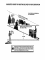
!1. SLOPE OPERATION
Slopes are a major factor related to loss-of-control
and
tipover accidents, which can result in severe injury or death.
All slopes require extra caution. If you cannot back up the
slope or if you feel uneasy on it, do not mow it.
DO:
•
Mow up and down slopes, not across.
•
Remove obstacles such as rocks, tree limbs, etc.
*
Watch for holes, ruts, or bumps. Uneven terrain could
overturn the machine. Tall grass can hide obstacles.
•
Use slow speed. Choose a low gear so that you will not have
to stop or shift while on the slope.
•
Follow the manufacturer's recommendations for wheel
weights or counterweights to improve stability.
•
Use extra care with grass catchers or other attachments.
These can change the stability of the machine.
•
Keep all movement on the slopes slow and gradual Do not
make sudden changes in speed or direction.
•
Avoid starting or stopping on a slope. If tires lose traction,
disengage the blades and proceed slowly straight down the
slope.
t
Use extra care in handlinggasoline andother fuels. They are
flammable and vapors are explosive.
Use only an approved container.
Never remove gas cap or add fuel with the engine
running. Allow engine to cool before refueling. Do not
smoke.
Never refuel the machine indoors.
Never store the machine or fuel container inside where
there is an open flame, such as a water heater.
Never run a machine inside a closed area,
Keep nuts and bolts, especially blade attachment bolts, tight
and keep equipment in good condition.
Never tamper with safety devices.
C',leck their proper
operation regularly.
Keep machine free of grass, leaves, or other debris build-up.
Clean oil or fuel spillage. Allow machine to cool before
storing.
Stop and inspect the equipment if you strike an object.
Repair, if necessary, before restarting.
Never make adjustments or repairs with the engine running.
Grass catchercomponents are subjecttowear, damage, and
deterioration, which couid expose moving parts or allow
objects to be thrown. Frequently check components and
replace with manufacturer's recommended parts, when necessary.
Mower blades are sharp and can cut. Wrap the blade(s) or
wear gloves, and use extra caution when servicing them.
Check brake oper:_tion frequently. Adjust and service as
required.
III
i|1
i
Look for this symbol to point out important safety precautions.
It means
CAUTION!!! BECOMEALERT!!!
YOUR
SAFETY IS INVOLVED.
i
DO NOT:
•
Donot turn on slopesunlessnecessary,and then, turnslowly
and gradually downhill, if possible.
•
Do notmow near drop-offs,ditches, or embankments. Themower could suddenly turn over if a wheel is over the edge
of a cliffor ditch, or if an edge caves in.
•
Do not mow on wet grass. Reduced traction could cause
sliding.
•
Do not try to stabilize the machine by putting yourfoot onthe
ground.
•
Do not use grass catcher on steep slopes.
I
i
IIIIIII
Hi
i L
CAUTION: Always disconnect spark plug
wireand placewirewhere it cannot contact
spark plug in order to prevent accidental
starting when setting up, transporting,
adjusting Or making repairs.
.
]
i
& WARNING A
The engine exhaust from this product contains chemicals known to the State of California to cause cancer, birth defects, or other
reproductive harm.
2
IIII
II
iii iiirl
PRODUCT SPECIFICATIONS
CONGRATULATIONS
on your purchase of a Sears
Tractor. It has been designed, engineered and manufactured to give you the best possible dependability and
performance.
Should you experience any problem you cannot easily
remedy, please contact your nearest Sears Authorized
Service Center/Department. We have competent, welltrained techniciansand the propertoolsto serviceor repair
this tractor.
Please read and retain this manual. The instructionswill
enable you to assemble and maintain your unit properly.
Always observe the "SAFETY RULES".
MODEL
NUMBER
917.259290
HORSEPOWER:
13.5
GASOLINE CAPACITY
AND TYPE:
1.25 GALLONS
UNLEADED REGULAR
OIL TYPE (API-SF/SG):
SAE 30 (above 32°F)
SAE 5W-30 (below 32°F)
OIL CAPACITY:
3 PINTS
SPARK PLUG:
(GAP: .030")
CHAMPION RJ19LM
STD361458
VALVE CLEARANCE:
INTAKE:
.005" - .007"
EXHAUST: .009" - .011"
GROUND SPEED (MPH):
FORWARD:
1st
2nd
3rd
4th
5th
6th
REVERSE:
SERIAL
NUMBER
DATE OF PURCHASE
THE MODEL AND SERIAL NUMBERS WILL BE FOUND
ON A PLATE UNDER THE SEAT.
YOU SHOULD RECORD BOTH SERIAL NUMBER AND
DATE OF PURCHASE AND KEEP IN A SAFE PLACE
FOR FUTURE REFERENCE.
MAINTENANCE
AGREEMENT
TIRE PRESSURE:
FRONT:
REAR:
CHARGING SYSTEM:
3 AMPS BATTERY
5 AMPS HEADLIGHTS
BATTERY:
AMP/H R:
MIN. CCA:
CASE SIZE:
BLADE BOLT TORQUE:
30-35 FT. LBS.
A Sears Maintenance Agreement is available on this product. Contact your nearest Sears store for details.
CUSTOMER RESPONSIBILITIES
°
Read and observe
•
Followa regular schedule in maintaining,
using your tractor.
the safety ruIes.
1.0
1.3
2.1
3.1
4.0
5.1
1.6
14 PSI
12 PSI
25
190
U1R
caring for and
with a spark arrester meeting applicable local or state laws
(if any). If a spark arrester is used, it should be maintained
in effective working order by the operator.
Followthe instructions under"Customer
Responsibilities" and "Storage" sections of this owneCs manual.
WARNING:
This tractor is equipped with an internal
combustion engine and should not be used on or near any
unimproved forest-covered,
brush-covered
or grass-covered land unless the engine's exhaust system is equipped
In the state of California the above is required by law
(Section 4442 of the California Public Resources Code).
Other states may have similar laws. Federal laws apply on
federal lands. A spark arrester for the muffler is available
through your nearest Sears Authorized Service Center/
Department (See REPAIR PARTS section of this manual).
•
LIMITED TWO YEAR WARRANTY ON CRAFTSMAN
RIDING EQUIPMENT
For two (2) years from the date of purchase, if this Craftsman Riding Equipmentis maintained, lubricatedand tuned up according
to the instructions in the owner's manual, Sears wilt repair or replace, free of charge, any parts found to be defective in material or
workmanship.
This Warranty does not cover:
•
Expendable items which become worn during normal use, such as blades, spark plugs, air cleaners, belts, etc.
•
Tire repTacement or repair caused by punctures from outside objects, such as nails, thorns, stumps, or glass.
•
Repairs necessary because of operator abuse, negligence, improper storage or accident or the faiiure to maintain the
equipment according to the instructions contained in the owner's manual.
•
Riding equipment used for commercial or rental purposes.
LIMITED 90 DAY WARRANTY ON BATTERY
For ninety (90) days from date of pumhase, if any battery included with this riding equipment proves defective in material or
workmanshipand our testingdetermines the battery wilt not hoid a charge, Sears will replace the battery at no charge.
IN-HOME WARRANTY SERVICE ONLYOUR CRAFTSMAN RIDING EQUIPMENT IS AVAILABLE AT NO-CHARGE FOR 30
DAYS FROM THE DATE OF PURCHASE; PLEA,SE CONTACT YOUR NEAREST SERVICE CENTER; AFTER 30 DAYS FROM
THE DATE OF PURCHASE, WARRANTY SERVICE IS AVAILABLE BY TAKING YOUR CRAFTSMAN RIDING EQUIPMENT TO*
YOUR NEAREST SEARS SERVICE CENTER. (iN-HOME WARRANTY SERVICE WILL STILL BE AVAILABLE AFTER 30 DAYS
FROM THE DATE OF PURCHASE BUT A STANDARD TRIP CHARGE WILL APPLY.) THIS WARRANTY APPLIES ONLY
WHILE THIS PRODUCT IS IN THE UNITED STATES.
This Warranty gives you specific legal rights,and you may aTsohave other rightswhich may van! from state to state.
SEARS, ROEBUCK
II II]
AND CO., D/817 WA, HOFFMAN
I
iiiii
3
ESTATES,
II
IL 60179
I
.............................
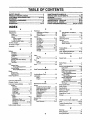
TABLE O
CONTEN:FS ..........................
i
SAFETY
PRODUCT
RULES
............................................................
SPECIFICATIONS
i i,,llll,
.......................
MAINTENANCE SCHEDULE ...................................... 15
SERVICE AND ADJUSTMENTS ............................ 19-24
STORAGE ................................................................... 25
TROUBLESHOOTING .......................... .................. 26-27
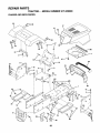
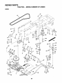
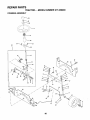
REPAIR PARTS - TRACTOR ................................. 30-47
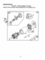
REPAIR PARTS - ENGINE .................................... 48-52
PARTS ORDERING/SERVICE ................ BACK COVER
2
......................................
,,,,,,,,,,,,,,,,,,,
,,,,
3
CUSTOMER
RESPONSIBILITIES
..................... 3, 15-18
WARRANTY
..................................................................
3
TRACTOR ACCESSORIES
..........................................
5
ASSEMBLY ................................................................
7-9
OPERATION ...........................................................
10-14
INDEX
A
E
Accessories ........................................... 5
Adjustments;
Brake ............................................ 21
Carburetor .................................... 24
Mower
Front-To-Back ......................... 20
Side-To-Side ........................... 20
Throttle Control Cable .................. 24
Air Filter, Engine ............................. 17-18
Air Screen, Engine .............................. 18
Assembly ............................................ 7-9
Electrical:
Interlocks and Relays .................. 23
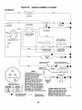
Schematic .................................... 29
Wiring Diagram ............................ 30
Engine:
Air Filter ................................... t7-18
Air Screen .................................... 18
Cooling Fins ................................. 18
Oil Change ................................... 17
Oit Level ....................................... 13
Oil Type ................................... 13,17
Preparation .................................. 13
Repair Parts ............................ 48-52
Starting ......................................... 14
Storage ........................................ 25
B
Battery:
Charging ........................................ 8
Cleaning ....................................... 17
Installation ...................................... 9
Levels ........................................ 8,16
Preparation .................................... 8
Starting with Weak Battery .......... 22
Storage ........................................ 25
Terminals ..................................... 17
Belt:
Motion Drive
Removal/Replacement ........... 21
Mower Belt(s)
Removal/Replacement ........... 21
B!ade:
Sharpening .................................. 16
Replacement ................................ 16
Brake Adjustment ................................ 21
C
Carburetor Adjustment ........................ 24
Controls, Tractor ................................. 11
Customer Responsibilities ............. 16-18
Engine:
Air Filter .................................... 17
Air Screen ................................ 18
Cooling Fins ............................. 18
Engine Oil ........................... 13,17
Fuel Filter ................................. 18
Spark Plug(s) ........................... 18
Tractor:
Battery ................................. 16-17
Blade ........................................ 16
Lubrication Chart ....:................ 15
Maintenance Schedule. ........... 15
Tire Care ....... :.................. 8,16,22
Transaxle ................................. 17
Cutting Height, Mower ........................ 12
O
F
Filter:
Air Filter ........................................
Fuel ..............................................
Fuel:
Type .............................................
Storage ........................................
Fuse ....................................................
17
18
14
25
23
H
Hood Removal/Installation .................. 23
L
Leveling Mower Deck .......................... 20
Lubrication:
Chart ............................................ 15
Engine .......................................... 17
M
Maintenance Schedule ....................... 15
Mower:
Adjustment, Front-to-Back ........... 20
Adjustment, Side-to-Side ............. 20
Blade Replacement ..................... 16
Blade Sharpening ........................ 16
Cutting Height ....... ....................... !2
Installation .................................... 19
Operation ..................................... 13
Removal ....................................... 19
Mowing Tips .............. _......................... 14
Muffler ................... ...._..
...................... ... 18
Spark Arrester ..L.:... .................. 3,40
Oil:
Cold Weather Conditions ........ 13,17
Engine .......................................... 17
Storage ........................................ 25
Operation ....................................... 10-14
Operating Mower ................................ 13
Options:
Accessories ......... ........................... 5
Spark Arrester ........................... 3,40
P
Parking Brake ................................ 11,12
Parts Bag .............................................. 6
Parts, Replacement/Repair ............ 30-47
Product Specifications.......................... 3
R
Repair Parts ................................... 30-47
S
Safety Rules ......................................... 2
Seat ............................... ........................ 8
Service and Adjustments ............... 19-24
Carburetor .................................... 24
Fuse ............................................. 23
Hood Removal/Installation ........... 23
Motion Drive Belt
Removal/Replacement ........... 21
Mower Belt(s)
Removal/Replacement ........... 21
Mower Adjustment
Front-to-Back .......................... 20
Side-to-Side ............................ 20
Mower Removal!Installation ......... 19
Tire Care .............................. 8,16,22
Slope Guide Sheet .............................. 55
Spark Plug(s) ...................................... 18
Specifications ........................................ 3
Starting the Engine ........................ 13-14
Steering Wheel ................................ 7,22
Stopping the Tractor ........................... 12
Storage ................................................ 25
T
Throttle Control Cable Adjustment ...... 24
Tires ............................................ 8,16,22
Trouble Shooting Chart .................. 26-27
Transaxle ............................................ 17
W
4
Warranty ................................................ 3
Wiring Diagram ................................... 30
Wiring Schematic ................................ 29
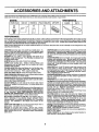
IES AND ATTACHMENTS
These accessories and attachments wereavailable throughmost Sears retail outlets and service centers when the tractorwas purchased.
Most Sears stores can order these items for you when you provide the model number of your tractor.
ENGINE
SPARK PLUG
MAINTENANCE
GAS CAN
ENGINE OIL
FUEL STABILIZER
AIR FILTER
BLADES
BELTS
PERFORMANCE
Sears offers a wide variety of attachments that fit your tractor. Many of these are listed below with brief explanations of how theycan hetp
you. This list was current at the time of publication; however, it may change in future years - more attachments may be added, changes
may be made in these attachments, or some may no longer be available or fit your model. Contact your nearest Sears store for the
accessories and attachments that are available for your tractor,
Most of these attachments do not require additional hitches or conversion kits (those that do are indicated) and are designed for easy
attaching and detaching.
AERATOR promotes deep root growth for a healthy lawn. Tapered 2.5-inch steel spikes mounted on 10-inch diameter discs
puncture holes in soil at close intervals to let moisture soak in.
Steel weight tray for increased penetration,
BAGGER lets you collect grass clippings and leaves for a
healthier, neater looking lawn. Two Permanex containers hold
30-gallon plastic bags.
BUMPER protects front end of tractor from damage.
CARTS make hauling easy. Variety of sizes available, plus
accessories such as side panel kits, tool caddy, cart cover,
protective mat and doily.
CORING AERATOR takes small plugsout of soil to allow moisture and nutrients to reach grass roots. 36-inch swath. 24
hardened steel coring tips. 150 lb. capacity weight tray.
EASY OIL DRAIN VALVE makes oilchanges easier, faster.
FRONT NOSE ROLLER canters in front of mower deckto reduce
chances of =scalping" on uneven terrain.
GANG HITCH lets youtow2 or3 pull-behindattachments at once,
such as sweepers, dethatchers, aerators (not for use with rollers,
carts or other heavy attachments).
GAUGE WHEELS on both sides of the mower deck reduce
chances of "scalping" on uneven terrain. Formower decks notso
equipped.
MULCH RAKEJDETHATCHER loosenssoil and flipsthatch and
matted leaves to lawn surfacefor easy pickup. Twenty springline
teeth. Usefultopreparebareareasforseeding. Availableforfront
or rear mounting.
HIGH PERFORMANCE REEL-ACTION
SPRING TINE DETHATCHER covers 36-inch wide path and
tosses thatch into large hopper. Mounts behind tractor.
MULCHING CLOSE-OUT PLATE KIT, once installed, lets you
mulch, discharge or bag clippings (bagger optional) without
changing blades. For models not equipped as 3-in-1 Convertible
mowers. See "MOWER" in the Repair Parts section of this
manual.
SNOW BLADEforsnow removal only. 14-inch high, 48-inch wide
biadeclears 42-inch pathwhen angledleft orright. Raises, lowers
with side lever. Adjustable skids; replaceable, reversible scraper
bar. (Use with tire chainsand wheel weights and/or rear drawbar
weight.)
SNOWTHROWER has40-inch swath. Drum-type auger handles
powdery and wet/heavy snow. Mounts easily with simple pin
arrangement. Discharge chute adjusts from tractor seat. 6-inch
diameter spout discharges snow 10 to 50 feet. Lift controlledat
tractor seat. (Use with chains and wheel weights and/or rear
drawbar weight.)
SPRAYERS use 12-volt DC electric motor that connects to the
tractor battery or other 12-volt source. Includes booms for
automatic spraying and hand held wand for spot spraying. Wand
has adjustable spray pattern. For applying herbicides, insecticides, fungicides and liquid fertilizers.
SPREADER/SEEDERS make seeding, fertilizing, andweed kiUing easy. Broadcast spreaders are also useful for granular deicers and sand.
SWEEPERS let you collect grass clippings and leaves.
TILLER has 5 hp engine and 36-inch swath to prepare seed beds,
cultivate and compostgarden residue. Tiller has its own built-in
liftand depth controlsystem and does NOT require a sleeve hitch.
Fitsany lawn, yard or garden tractor. Simply hook up tothe tractor
drawbar and go! Optional accessories convert unit for
dethatching, aerating, hilfing...without tools.
TIRE CHAINS are heavy duty; closely spaced extra-large cross
linksgive smooth ride, outstanding traction.
TRACTOR CAB has heavy duty vinyl fabric over tubular steel
frame, ABS plastictop;clear plastic windshieldoffers360 degree
visibility. Hinged metal doors with catch. Keeps operator warm
and dry. Remove vinyl sides and windshields for use as sun
protector in summer. Optional accessories include: tinted/
tempered solid safety glasswindshield with hand operated wiper;
12-volt amber caution light for mounting on cab top.
VACS_r powerfulcollectionof heavy grass clippingsand leaves.
Option) wand attachment to pick up debris in hard-to-reach
pib.€_i. VACtCHIPPER includes a chipper-shredder.
WEIGHT BRACKET for drawbar for snow removal applications.
Uses (t) 55 lb. weight.:
WHEEL WEIGHTS for rear wheeIs provide needed traction for
snow removal or dozing heavy materials.
RAMP TOPS AND FEET let you Ioad and unloadtractor from a
pickup truck. Use with 2 x 8 or 2 x 10 lumber.
ROLLER for smoother lawn surf.ace. 36:inch wide, .18-inch
diameterwater-tightdrum holdsupto3901bs.ofweight. Rounded.
edges prevent harm to turf. Adjustable scraper automatically
cleans drum.
5
iiiii
iiiiiiiiii
,
i
iiii
i
ii
IH
IIIII1"""1
OF HARDWARE
...........
""'1,
±,,
,,ill ,,,,,,,,,,,,,,,,,,,,,,,,,
iiiiiii
IIIHI
IIIIII
ii1,1,,,,,,i
Illllllllll
Illl Illllllll
IIIIIIIIIIIII
PACK
i
IIIIIIIIIII
i i
i
Parts Bag contents shown full size
II I
I I IIIII
i
iiiiiii i,11111111
i
Parts packed separately
Ill
I
I IIIIIIIIIII
I
(2) Sheet
Metal
in carton
I IIIIIII
i
IIIL
Seat
#10-16
x 1/2
Screws
O
(1) Locknut 3/8-24
Video
Cassette
Steering
Wheel
(1) Large Flat Washer
"!
I
!
I
|
Steering
Boot
!
I
I
I
I
Parts Bag
Manual
(1) Hex Bolt 1!2-13 x 1
(1) Shoulder Bolt 5/16-18
ii.t
iii
Parts bag contents not shown full size
iJr
(1) LockWasher
,
1Q/2
Wheel
Steering
Insert
_
Steering Whee!
Adapter
(1) Washer 17/32
x 1-3/16 x 12 Gauge
_
Bushing
teering
_(2)
Keys
I !fllltltI!1111f1111tlIItI
1
(2) Hex Bolts 1/4-20 x 3/4
(2) Hex Nuts 1/4-20
(2) Lock Washers 1/4
Slope Sheet
(2) Washers 9/32 x 5/8 x 16 Gauge
II
6
LY
i
Wl i|l ii
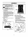
Your new tractor has been assembled at the factory with exception of those parts left unassembted for shipping purposes.
To ensure safe and proper operation of your tractor all parts and hardware you assemble must be tightened securely. Use
the correct tools as necessary to insure proper tightness.
TOOLS REQUIRED FOR ASSEMBLY
.__31_EERING
A socket wrench set will make assembly easier. Standard
wrench sizes are listed.
(1) 5/16" wrench
(1) 3/4" wrench
(2) 7/16" wrenches
Tire pressure gauge
(1) 1/2" wrench
Utility knife
(1) 9/16" wrench
When right or left hand is mentioned in this manual, it
means when you are in the operating position (seated
behind the steering wheel).
WHEELINSERT
_4LOCKNUT
(_LARGEFLAT
STEERING WHEEL
STEERING
BUSHING
TO REMOVE TRACTOR FROM CARTON
TABS
UNPACK CARTON
•
•
°
WASHER
Remove att accessible loose parts and parts cartons
from carton (See page 6).
Cut, from top to bottom, along lines on a]l four corners
of carton, and lay panels flat.
Check for any additional loose parts or cartons and
remove.
SHEET
METAL
SCREW
(ASSEMBLY
POSITION)
;:Z
BE FORE ROLLING TRACTOR OFF SKID
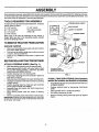
ATTACH STEERING
WHEEL (See Fig. 1)
•
•
Slide the steering bushing over the steering shaft.
Raise steering shaft forward untilscrew holes in dash
line up with steering bushing. Install two (2) sheet
metal screws and tighten securely.
•
Positionsteering boot over steering shaft.
°
Place tabs of steering boot over tab slots in dash and
push down to secure.
•
Slide steeringwheel adapter ontouppersteering shaft.
•
Positionfront wheels of the tractorso they are pointing
straight forward.
•
Position steering wheel so cross bars are horizontal
(left to right) and slide onto adapter.
•
Assemble large flat washer and 3/8-24 locknut and
tighten securely.
° Snap steering wheel insert into center of steering
wheel.
•
Remove protective plasticfrom tractor hood and grill.
IMPORTANT:CHECK FOR AND REMOVE ANY STAPLES
IN SKID THAT MAY PUNCTURE TIRES WHERE TRACTOR
IS TO ROLL OFF SKID.
STEERING SHAFT
(SHIPPING POS_ION)
FIG. 1
TO ROLLTRACTOR OFFSKID (See Operation
section for location and function of controls)
•
•
°
•
°
7
Press lift lever plungerand raise attachment lift lever to
its highest position.
Release parking brake by depressing clutch!brake
pedal.
Place gearshift lever in neutral (N) position.
Roll tractor backwards off skid.
Remove banding holding discharge guard up against
tractor.
ASSEMBLY
CONNECT
BATTERY
(See Figs. 2 and 3)
i.ii
i.
,,,,,,,,,,
,,,,,,,,
CAUTION: Do not short battery terminals. Before connecting battery, remove metal bracelets, wristwatch
bands, rings, etc.
SEAT
PAN
Positive terminal must be connected
first to prevent sparking from accidental grounding.
II
•
IIIIIII
ummmmmmm
,
•
Remove cardboard packing from seat pan and lift seat
pan to raised position.
Open battery box door.
•
Remove terminal protective caps and discard.
•
if this battery is put into service after month and year
indicated on label (label located between terminals)
charge battery for minimum of one hour at 6-10 amps.
*
First connect RED battery cable to positive(+) terminal
with hex bolt, flat washer, lock washer and hex nut as
shown. Tighten securely.
•
•
BOX DOOR
FIG. 3
Connect BLACK grounding cable to negative (-) terminal with remaining hex bolt, flat washer, lock washer
and hex nut. Tighten securely.
Close battery box door.
INSTALL SEAT (See Fig. 4)
Adjust seat before tightening adjustment bolt.
Open battery box door for:
°
•
Remove cardboard packing on seat pan.
Place seat on seat pan and assembte shoulder bolt.
•
Inspection for secure connections (to tighten hardware).
°
Assemble adjustmentbolt, Iockwasherand flatwasher
loosely. Do not tighten.
•
Inspection for corrosion.
•
Tighten shoulder bolt securely.
•
Testing battery.
,
Jumping (if required).
•
•
•
Periodic charging.
Lower seat intooperating positionand sit on seat.
Slide seat untila comfortablepositionisreachedwhich
altows you to press clutch!brake pedal all the way
down.
•
Get off seat without moving its adjusted position.
•
Raise seat and tighten adjustment bolt securety.
DISCARD TERMINAL PROTECTIVE
CAPS
/
POSITIVE
(RED) CABL_
HEX
NUT
v!
WASHER
LOCK
FLAT
WASHER
SEAT
SEAT PAN
SHOULDER
BOLT
BOLT
NEGATIVE
(BLACK) CABLE
FIG. 2
FLAT WASHER
ADJUSTMENT
BOLT
LOCK WASHER
FIG. 4
8
ill i ii,,,,, ,i
|
i
,lllllll
,,i ,,, i
ASSEMBLY
i
H
v"CHECKLIST
CHECK TIRE PRESSURE
The tires on your tractor were overinflated at the factoryfor
shipping purposes. Correct tire pressure is importantfor
best cutting performance.
•
Reduce tire pressure to PSI shown in "PRODUCT
SPECIFICATIONS" on page 3 of this manual.
BEFORE YOU OPERATE AND ENJOY YOUR NEW
TRACTOR, WE WISH TO ASSURE THAT YOU RECEIVE
THE BEST PERFORMANCEAND SA TISFACTION FROM
THIS QUALITY PRODUCT.
PLEASE REVIEW THE FOLLOWING CHECKLIST:
CHECK DECK LEVELNESS
,I
,f
All assembly instructionshave been completed.
No remaining loose parts in carton.
,f
Battery is properly prepared and charged. (Minimum
1 hour at 6 amps).
Seat is adjusted comfortably and tightened securely.
For best cutting results, mower housing should be properly
leveled. See 'q'O LEVEL MOWER HOUSING" in the
Service and Adjustments section of this manual.
CHECK
BELTS
FOR
PROPER
POSITION
4
OF ALL
See the figures that are shown for replacing motion and
mower blade drive belts in the Service and Adjustments
section of this manual. Verify that the belts are routed
correctly.
,!
AIJtires are properlyinflated. (For shippingpurposes,
the tires were overinflated at the factory).
,/
Be sure mower deck is properly leveled side-to-side/
front-to-rear for best cutting results. (Tires must be
properly inflatedfor leveling).
Check mower and drive belts. Be sure they are routed
properly around pulleys and inside all belt keepers.
4
CHECK BRAKE SYSTEM
,/
After you learn how to operate your tractor, check to see
that the brake is properly adjusted. See 'q'O ADJUST
BRAKE" in the Service and Adjustments section of this
manual
Check wiring. See that all connectionsare stillsecure
and wires are properly clamped.
WH/LE LEARNtNG HOW TO USE YOUR TRACTOR, PAY
EXTRA ATTENTION TO THE FOLLOWING IMPORTANT
ITEMS:
/
Engine oil is at proper level.
#" Fuel tank is filled with fresh, clean, regular unleaded
gasoline.
,/ Become familiar with all controls - their Iocation and
function. Operate them before you start the engine.
,#
9
Be sure brake system is in safe operating condition.
i, ,,,,,,,,,,,,,,,,,,,,,,,,
,,,,,,,,,,,,,,,,,,,,
,,,,
,,,,,,,,,,
...........................................
OPERATION
............
ii,
iuuuuuuuuum
mllll
luuu
ml
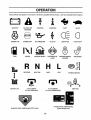
These symbols may appear on your tractor or in literature supplied withthe product. Learn and understand their meaning.
A ,
BATTERY
CAUTION OR
WARNING
REVERSE
FORWARD
FAST
SLOW
ENGINE ON
ENGINE OFF
OIL PRESSURE
CLUTCH
LIGHTS ON
LIGHTS OFF
FUEL
CHOKE
MOWER HEIGHT
DIFFERENTIAL
LOCK
PARKING BRAKE
LOCKED
UNLOCKED
L
!
MOWER LIFT
R N H L
REVERSE
NEUTRAL
ATTACHMENT
CLUTCH ENGAGED
HIGH
LOW
ATTACHMENT
CLUTCH DISENGAGED
PARKING BRAKE
IGNITION
HYDROSTATIC FREE WHEEL
(Hydro Models only)
DANGER, KEEP HANDS AND FEET AWAY
10
iill
l
,HIIII
ii,,ll
IIH,,,,,,IIIIIIIIIIlll
III1"1
I
II
I,,lllll
HHI
I
I
OPERATION
i
lira
ii
i
i
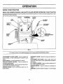
KNOW YOUR TRACTOR
READ THIS OWNER'S
MANUAL AND SAFETY RULES BEFORE OPERATING
YOUR TRACTOR
Compare the illustrationswith yourtractortofamiliarizeyourselfwiththe locationsofvariouscontrolsand adjustments. Save
this manual for future reference.
AMMETER
LIGHT
SWITCH
ATTACHMENT
CLUTCH LEVER
IGNITION
SWITCH
221
UFT
LEVER
THROTTLE/
CHOKE
CONTROL
MOWER DECK
HEIGHT ADJUSTMENT
POSITIONS
CLUTCH/
BRAKE
PEDAL
_PARKING
BRAKE
GEARSHIFT
LEVER
FIG. 5
Our tractors conform to the safety standards of the American National Standards Institute.
ATTACHMENT CLUTCH LEVER: Used to engage the
mower blades, or other attachments mounted to your
tractor.
LIGHT SWITCH: Turns the headlights on and off.
THROI-rLE/CHOKE CONTROL: Used for starting and
controllingengine speed.
CLUTCH/BRAKE PEDAL: Used fordeclutching and braking the tractor and starting the engine.
PARKING BRAKE: Locks clutch/brake pedal into the
GEARSHIFT LEVER: Selects the speed and direction of
tractor.
ATTACHMENT LIFT LEVER: Used to raise, lower, and
adjust the mower deck or other attachments mounted to
your tractor.
LIFT LEVER PLUNGER: Used to retease attachment lift
lever when changing its position.
IGNITION SWITCH: Used for starting and stopping the
engine.
AMMETER: Indicates battery charging (+) or discharging
brake position.,
(-).....
_ ,
11
_.
•
o,
.
ii i
1,1,,,,,,,i
i,i iiiiiiiiiiiiii
ii
i
,,,
,, ,,,,,,,,,,
RATION
i
iiii
iiiiii
iiiiiiiiii
IIII iiiiiiiiiiiiiiiiiiiiiii
iiiiiiiiiiiiii
iiiiiiiii
iiiiiiii
iii
iiiiiiiiiiiiiiiiiiiiii
IIII
iiii
i
iiiiiiiiiiiiiiii
JIHIIIIIIIIIIIIIII
i
iiiiii iii
]
II
The operation of any tractor can result in foreign objects thrown into the eyes, which
can result in severe eye damage. Always wear safety glasses or eye shields while
operating your tractor or performing any adjustments or repairs. We recommend a wide
vision safety mask over the spectacles or standard safety glasses.
i,i
........................
|
HOW TO USE YOUR TRACTOR
NOTE: Under certain conditions when tractor is standing
idle with the engine running, hot engine exhaust gases may
cause 'browning of grass. To eliminate this possibility,
always stop engine when stopping tractor on grass areas.
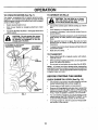
TO SET PARKING BRAKE (See Fig. 6)
Your tractor is equipped with an operator presence sensing
switch. When engine is running, any attempt by the
operator to leave the seat without first setting the parking
brake will shut off the engine.
•
Depress clutch/brake pedal into full"BRAKE" position
and hold.
•
Place parking brake lever in"ENGAGED" position and
release pressure fromclutch/brake pedal. Pedal should
remain in "BRAKE position. Make sure parking brake
will hold tractor secure.
ATTACHMENT CLUTCH LEVER
"ENGAGED" POSITION
................................
CAUTION:Always
ing
the as
operator's
to empty
pletely,
described position;
above, before
leavgrass catcher, etc.
TO USE THROTTLE
"DISENGAGED"
POSITION
Operating engine at less than full throttle reduces the
battery charging rate.
•
Full throttle offers the best bagging and mower performance.
BACKWARD
°
Start tractor with clutch/brake pedal depressed and
gearshift lever in neutral (N) position.
°
Move gearshift lever to desired position.
° Slowly release clutch/brake pedal to start movement.
IMPORTANT: BRING TRACTOR TO A COMPLETE STOP
BEFORE SHIFTING OR CHANGING GEARS. FAILURE
TO DO SO WILL SHORTEN THE USEFUL UFE OF YOUR
TRANSAXLE.
TO ADJUST MOWER CUTTING
(See Fig. 5)
\
PARKING BRAKE
"DISENGAGED" POSITION
HEIGHT
The position of the attachment lift lever determines the
cutting height.
° Grasp lift lever.
FIG. 6
•
(See Fig. 6)
MOWER BLADES ° Move attachment clutch lever to "DISENGAGED" position.
GROUND DRIVE •
Depress dutch!brake pedal into full "BRAKE" position.
•
Move gearshift lever to neutra[ (N) position.
ENGINE .
°
Move throttle control to slow (,gb) position.
NOTE: Failure to move throttle control to slow (-=_)
position and allowing engine to idle before stopping may
cause engine to "backfire".
•
Turn ignitionkey to "OFF" position and remove key.
Always remove key when leaving tractor to prevent
unauthorized use.
•
Never use choke to stop engine.
AND
The directionand speed of movement is controlledby the
gearshift lever.
PARKING
BRAKE
"ENGAGED"
_OSITION
GEARSHIFT
LEVER
STOPPING
(See Fig. 6)
°
TO MOVE FORWARD
(See Fig. 6)
"BRAKE"
\
POSITION
CLUTCH/BRAKE PEDAL
"DRIVE = POSITION
CONTROL
Always operate engine at full throttle.
IGNITION
KEY
THROTTL_CHOKE_
CONTROLLEVER
stop tractor com,
Press plunger with thumb and move lever to desired
position.
The cutting height range is approximately 1-1/2 to 4". The
heights are measured from the ground to the blade tip with
the engine not running. These heights are approximate
and may vary depending upon soil conditions, height of
grass and types of grass being mowed.
°
•
12
The average lawn should be cut to approximately 2-1/2
inches during the cool season and to over 3 inches
during hot months. For healthier and better'.looking
lawns, mow often and after moderate growth.
For best cutting performance, grass over 6 inches in
height should be mowed twice. Make the first cut
relatively high; the second to desired height.
iiiiiiiiii
iii
HI I
OPERATION
TO OPERATE
TO OPERATE
MOWER (See Fig. 7)
Your tractor is equipped with an operator presence sensing switch. Any attempt by the operatorto leave the seat
withthe engine running and the attachment clutchengaged
will shut off the engine.
i iiiii
Select desired height of cut.
Start mower blades by engaging attachment clutch
control
°
TO STOP MOWER BLADES - disengage attachment
clutch control.
i
=
i
III
I IIIIIIIIIIIII [
ATTACHMENT CLUTCH LEVER
"DISENGAGED" POSITION
"ENGAGED"
POSITION
II
I
I
HI
I
I
°
Avoid stopping or changing speed on hilts.
•
If slowing is necessary, move throttle control lever to
slower position.
If stopping is absolutely necessary, push clutch/brake
pedal quickly to brake position and engage parking
brake.
°
Move gearshift lever to 1st gear. Be sure you have
allowed room for tractor to roll slightly as you restart
movement.
°
To restart movement, slowly release parking brake and
clutch/brake pedal.
•
Make all turns slowly.
I
ATTACHMENT
LIFT LEVER
HIGH POSITION
I Ill
Choose the slowest speed before starting up or down
hills.
°
III
I
II I,I,,HI,I_
•
,1
without either the entire grass catcher,
CAUTION:
operate or
thethe
mower
on mowers Do
so not
equipped,
discharge guard in place.
II
I
hills with slopes greater than 15 ° and
CAUTION:
not drive
up or down
do not drive Do
across
any slope.
II
•
•
ON HILLS
i ii IIIII,,,IIIIIIH
TO TRANSPORT
•
Raise attachment lift to highest position with attachment liftcontrol.
°
When pushingor towingyourtractor, be sure gearshift
lever is in neutral (N) position.
Do not push or tow tractor at more than five (5) MPH.
°
NOTE: To protect hood from damage when transporting
yourtractoron a truckor atrailer, be sure hood isclosed and
secured totractor. Use an appropriatemeans oftying hood
to tractor (rope, cord, etc.).
BEFORE STARTING THE ENGINE
CHECK ENGINE OIL LEVEL (See Fig. 12)
°
•
DISCHARGE
GUARD
FIG. 7
13
The engineinyourtractor has been shipped, fromthe
factory, already filled with summer weight oil.
Check engine oil with tractor on level ground.
•
Remove oilfillcap!dipstickand wipe clean, reinsertthe
dipstick and screw cap tight, wait for a few-seconds,
remove and read oil lever, if necessary, add oil until
"FULL" mark on dipstick is reached. Do not overfill.
•
For cold weather operation you should change oilfor
easier starting (See "OIL VISCOSITY CHART" in the
Customer Responsibilitiessection of this manual).
•
To change engine oil, see the Customer Responsibilities section in this manual.
ii
i i,
i
ii,,llllllllllllll
ii
i
illll ii,
i i
ii H
I
Illl,,I
ATION
ii
I IIIIIIIII
IIIIIIIIIIIIIIIIII
I IIIIIII
ADD GASOLINE
Fill fuel tank. Use fresh, clean, regular unleaded
gasoline with a minimum of 87 octane. (Use of leaded
gasoline will increase carbon and lead oxide deposits
and reduce valve life). Do not mix oil with gasoline.
Purchase fuet in quantities that can be used within 30
days to assure fuel freshness.
IMPORTANT: WHEN OPERATING IN TEMPERATURES
BELOW 32°F(0°C), USE FRESH, CLEAN WINTER GRADE
GASOLINE TO HELP INSURE GOOD COLD WEATHER
STARTING.
•
I
\
HIIII
I
I
When starting the engine for the first time or if the engine
has run out of fuel, it will take extra cranking time to move
fuel from the tank to the engine.
•
Move attachment clutch to "DISENGAGED" position.
Insertkey [ntoignitionand turn keyclockwise to"START"
position and release key as soon as engine starts. Do
not run starter continuously for more than fifteen seconds per minute. If the engine does not start after
several attempts, move throttle control to fast (,_)
position, wait a few minutes and try again. If engine still
does not start, move the throttle control back to the
choke ([\1) position and retry.
I IIIII
I
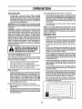
The attachments can also be used dudng the engine
warm-up period.
•
Drive so that clippings are discharged onto the area
that has been cut. Have the cut area to the right of the
machine. This will result in a more even distribution of
clippings and more uniform cutting.
•
When mowing large areas, start by turning to the right
so that clippings will discharge away from shrubs,
fences, driveways, etc. After one or two rounds, mow
in the opposite direction making left hand turns until
finished (See Fig. 8 ).
•
tf grass is extremely tall, it should be mowed twice to
reduce load and possible fire hazard from dried clippings. Make first cut relatively high; the second to the
desired height.
Do not mow grass when it is wet. Wet grass will plug
mower and leave undesirable clumps. Allow grass to
dry before mowing.
°
Always operate engine at full throttle when mowing to
assure better mowing performance and proper discharge of material. Regulate ground speed by selecting a low enough gear to give the mower cutting
performance as well as the quality of cut desired.
•
When operating attachments, select a ground speed
that will suit the terrain and give best performance of
the attachment being used.
f
WARM WEATHER STARTING (50 ° F and above)
•
When engine starts, movethe throttle control to the fast
(,_) position.
•
I
Mower should be properly leveled for best mowing
performance. See'q'O LEVEL MOWER HOUSING" in
the Service and Adjustments section of this manual.
The left hand side of mower should be used for trimming.
•
•
Move throttle control to choke (_) position.
Note: Before starting, read the warm and cold starting
procedures below.
•
II
•
TO START ENGINE (See Fig. 6)
Depress clutch/brake pedal and set parking brake.
Place gear shift lever in neutral (N) position.
I
Tire chainscannotbe used when the mower housing is
attached to tractor.
•
III
•
•
i
MOWING TIPS
IIIII
IIII
IIIIIIIIIIIIIIIIIIIIII
•
filler neck. Do not overfill. Wipe off any
spilled oil or fuel. Do not store, spill or
CAUTION:
to an
bottom
gas tank
use
gasolineFill
near
open of
flame.
I
IIIIIIIIIIIIIIIIIIII
NOTE: if at a high altitude (above 3000 feet) or in cold
temperatures (below 32 F) the carburetor fuel mixture may
need to be adjusted for best engine performance. See 'q'O
ADJUST CARBURETOR" in the Service and Adjustments
section of this manual.
WARNING: Experience indicates that alcohol blended
fuels (called gasohol or using ethanol or methanol) can
attract moisture which leads to separation and formation of
acids during storage. Acidic gas can damage the fuel
system of an engine while in storage. To avoid engine
problems, the fuel system should be emptied before storage of 30 days or longer. Drain the gas tank, start the
engine and let it run until the fuel lines and carburetor are
empty. Use fresh fuel next season. See Storage Instructions for additional information. Never use engine or
carburetor cleaner products in the fuel tank or permanent
damage may occur.
b
II
COLD WEATHER STARTING ( 50 ° F and below)
•
When engine starts, a.llqwengine to run with the throttle
control in the choke ._%,1)
position until the engine runs
roughly, then move tl'irdttle control to fast (,_) position.
This may require an engine warm-up period from
several seconds to several minutes, depending on the
temperature.
°
i
I I
The attachments and ground drive can nowbe used. If ;
the engine does not accept the load, restart the engine
and allow it to warm up for one minute using the choke ; "
as described above.
(
i
,ll
FIG. 8
14
IBILITIES
CUSTOMER
MAINTENANcElll
I
"'
SCHEDULE'' ""'"' ' '"
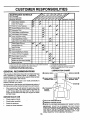
REGULAR SERV!CE
...........
" .......................
J____
If
.... /___SERVICE
DATES
......,_,
CheckTire Pressure
Checkfor LooseFasteners
C
R Sharpen/Replace
MowerBtades
_6 4
T
0
R
v'
v'
CheckBattery
Level/Recharge
CleanBattery
andTerminals
CheckTransaxTe
Cooling
Adjust
BladeBelt(s)
Tension
i
_1#5
ii
IIIIIII
iiiiiii
i
v'
CheckEngine
OilLevel
ChangeEngineOil
V'0
V'
1_,21,
..........
V'
V',
E
.....
Clean Air Screen
G i Inspect MufflerlSpark
I
ii
v'
Clean Air Filter
N
v'
..........
Adjust
Motion
Drive
Belt(s)
Tension
ii
v'
v'
Arrester
ReplaceOil Filter(If equipped)
v'2
Fins
v' v'
ReplaceSparkPlug
ReplaceAirFilterPaperCartridge
V'2
V"
ReplaceFuelFilter
12 3 =4 -
Change more Often when operating under a heavy load or in high ambient temperatures.
Service more often when operating in dirty or dusty conditions.
If equipped with oil tilter, change oil every 50 hours.
Replace blades more often when mowing in sandy soil.
5 * ff equipped with ad|ustable system,
6 - Not required if equipped with maintenance*free battery,
7 - Tighten front axle pivot bolt to 35 ft.-lbs, maximum.
Do notovertJghten.
LUBRICATION
GENERAL RECOMMENDATIONS
CHART
(_) SPINDLE ZERK
The warrantyon thistractor does not cover itemsthat have
been subjected to operator abuse or negligence. To
receive full value from thewarranty, operatormustmaintain
tractor as instructedin this manual.
(_
"FRONT WHEEL (_)
BEARING ZERK
BEARING ZERK
Some adjustments will need to be made periodically to
properly maintain your tractor.
®
All adjustments in the Service and Adjustmentssection of
this manual shouldbe checked at least once each season.
•
®
Once a year you should replace the spark plug, clean
or replace air filter, and check blades and beFts for
wear. A new spark plug and clean air filter assure
proper air-fuel mixture and help your engine run better
and last longer.
CLUTCH
PIVOT(S)
BEFORE EACH USE
•
•
•
•
Check engine oil level
Check brakeoperati0n.
• (_) SAE 30 OR "lOW30 MOTORO]L
' " ;
"
(_) GENERAL PURPOSE GREASE
Check tire pressure.
Check for loose fasteners.
(_) REFER TO CUSTOMER RESPONSIBILITIES
"ENGINE"
SECTION
IMPORTANT:
DO NOT OIL OR GREASE THE PIVOT POINTS
WHICH HAVE SPECIAL NYLON BEARINGS.
VISCOUS LUBRICANTS WILL ATTRACT DUST AND DIRT THAT WILL SHORTEN
THE LIFE OF THE SELF-LUBRICATING
BEARINGS.
IF YOU
FEEL THEY MUST BE LUBRICATED,
USE ONLY A DRY, POWDERED GRAPHITE TYPE LUBRICANT SPARINGLY.
15
iiiii
i
i
CUSTOMER
ii,,,,,m
ii
,,,,,
i iiii
i iiiiiiiiiii
iiiiiiiiii
ii
SIBILITIES
TRACTOR
TO SHARPEN
Always observe safety ruleswhen performingany maintenance.
Care should be taken to keep the blade balanced. An
unbalanced blade willcause excessive vibrationand eventual damage to mower and engine.
BRAKE OPERATION
•
If tractor requires more than six (6) feet stopping distance
at highspeed in highestgear, then brake mustbe adjusted.
(See '_TOADJUST BRAKE" in the Service and Adjustments section of this manual).
TIRES
•
•
•
•
.
•
Maintain proper air pressure in all tires (See "PRODUCT SPECIFICATIONS" on page 3 of this manual).
Keep tires free of gasoline, oil, or insect control chemicals which can harm rubber.
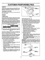
BLADE (See Fig. 10)
The bladecan be sharpened with a file or on a grinding
wheel. Do not attempt to sharpen while on the mower.
To check blade balance, you will need a 5/8" diameter
steel bolt, pin, ora cone balancer. (When usingacone
balancer, follow the instructions supplied with balancer).
Slide blade on to an unthreaded portion of the steel bolt
or pin and hold the bolt or pin parallel with the ground.
If blade is balanced, it should remain in a horizontal
position. If either end of the blade moves downward,
sharpen the heavy end until the blade is balanced.
NOTE: Do not use a nail for balancing blade. The lobes of
the center hole may appear to be centered, but are not.
Avoid stumps, stones, deep ruts, sharp objects and
other hazards that may cause tire damage.
BLADE CARE
CENTER HOLE
For best results mower blades must be kept sharp. Replace bent or damaged blades.
BLADE REMOVAL
/"
/
(See Fig. 9)
•
Raise mower to highest position to allow access to
blades.
•
Remove hex bolt, lock washer and flat washer securing blade.
•
install new or resharpened blade with trailing edge up
towards deck as shown.
•
Reassemble hex bolt, lock washer and flat washer in
exact order as shown.
OR PIN _J
FIG. 10
•
Tighten bolt securely (30-35 Ft. Lbs. torque).
IMPORTANT: BLADE BOLT tS GRADE 8 HEATTREATED.
BATTERY
NOTE: We do not recommend sharpening blade - but if
lou do, be sure the blade is balanced.
Your tractor has a battery charging system which is sufficient for normal use, However, periodic charging of the
battery with an automotive charger will extend its life.
MANDREL
ASSEMBLY
BLADE
\
Keep battery and terminals clean.
•
•
Keep battery bolts tight.
Keep small vent holes open.
•
Recharge at 6-10 amperes for 1 hour.
TO CLEAN BATTERY AND TERMINALS
Corrosion and dirt on the battery and terminals can cause
the battery to "leak" power.
TRAILING
EDGE UP
FLAT WASHER _
LOCKWASHER
•
_
/
_'__
_'HEX
•
Open battery box door.
•
Disconnect BLACK battery cabie first then RED battory cable and remove battery from tractor.
•
•
Rinse the battery with plain water and dry.
Clean terminals and battery cable ends with wire brush
until bright.
•
Coat terminals with grease or petroleum jelly.
•
Reinstall battery (See "CONNECT BATTERY" in the
Assembly section of this manual).
BOLT (GRADE 8)*
*A GRADE 8 HEAT TREATED BOLT CAN BE
IDENTIRED BY SIX LINES ON THE BOLT HEAD.
FIG. 9
16
iiiiiiiiiiiiiiiiii
ii
CUSTOMER
iiiiiiiiiiiiiiiiiiii
iii
ii ii
RESPONSIBI
V-BELTS
Check V-belts for deterioration and wear after 100 hours of
operation and replace if necessary. The belts are not
adjustable. Replace belts if they begin to slip from wear.
TRANSAXLE
OIL FILL
CAP/DIPSTICK
COOLING
Keep transaxle free from build-up of dirt and chaff which
can restrict cooling.
OIL DRAIN
PLUG
ENGINE
LUBRICATION
FIG. 12
Only use high quality detergent oil rated with API service
classificationSF or SG. Select the oil'sSAEviscositygrade
according to your expected operating temperature.
AIR FILTER (See Fig. 13)
NOTE: Although multi-viscosity oils (5W30, 10W30 etc.)
improve starting in cold weather, these multi-viscosity oils
will result in increased oil consumption when used above
32°F. Check your engine oil level more frequently to avoid
possible engine damage from running low on oil.
SAE VISCOSITY GRADES
4
oF
i,
-20 °
°c
-_0 _
0_
30 °
-_o° -_o
TEMPERATURE
RANGE
32 °
40 °
oo
ANTICIPATED
60°
_°
BEFORE
80 °
soo
100 o
3o° 40°
.....
NEXT OIL CHANGE
FIG. 11
Change the oil after the first two hours of operation and
every 25 hours thereafter or at least once a year if the
tractor is not used for 25 hours in one year.
Check the crankcase oil level before starting the engine
and after each eight (8) hours of operation. Tighten oil fill
cap/dipstick securely each time you check the oil level.
TO CHANGE ENGINE OIL (See Figs. 11 and 12)
Determine temperature range expected before oil change.
All oil must meet API service classification SF or SG.
•
Be sure tractor is on level surface.
•
Oil will drain more freely when warm.
•
Catch oil in a suitable container.
•
Remove oil fill cap/dipstick. Be careful not to allow dirt
to enter the engine when changing oil.
•
Remove drain plug.
•
After oil has drained completely, replace oiI drain plug
and tighten securely.
•
Refill engine with oil through oil fill dipstick tube. Pour
slowly. Do not overfill. For approximate capacity see
"PRODUCT SPECIFICATIONS" on page 3 of this
manual.
•
Use gauge on oil fill cap/dipstick for checking level. Be
sure dipstick cap is tightened securely for accurate _
reading. Keep oil at "FULU' line on dipstick.
Your engine will not run properly using a dirty air filter.
Clean the foam pre-cleaner after every 25 hours of operation or every season. Service paper cartridge every 100
hoursof operationor every season, whichever occursfirst.
Service air cleaner more often under dusty conditions.
•
Remove knob(s) and cover.
TO SERVICE PRE-CLEANER
•
Slide foam pre-cTeaner off cartridge.
•
Wash it in liquid detergent and water.
•
Squeeze it dry in a clean cloth.
•
Saturate it in engine oil. Wrap it in clean, absorbent
cloth and squeeze to remove excess oil.
•
If very dirty or damaged, replace pre-cleaner.
•
Reinstall pre-cleaner over cartridge.
•
Reinstall cover and secure with knob(s).
TO SERVICE CARTRIDGE
•
Remove cartridge nut.
•
Carefully remove cartridge to prevent debris from
entering carburetor. Clean base carefully to prevent
debris from entering carburetor.
•
Clean cartridge by tapping gentlyon flat surface, if very
dirty or damaged, replace cartridge.
•
Reinstall cartridge, nut, precleaner, cover and secure
with knob(s).
IMPORTANT:
PETROLEUM SOLVENTS, SUCH AS
KEROSENE, ARE NOT TO BE USED TO CLEAN THE
CARTRIDGE. THEY MAY CAUSE DETERIORATION OF
THE CARTRIDGE. DO NOT OIL CARTRIDGE. DO NOT
USE PRESSURIZED
AIR TO CLEAN OR DRY
CARTRIDGE.
COVER
KNOB
_
FOAM
PRE-CLEANER
17
/
_
_"BASE
FIG. 13
CARTRIDGE
,i iiiiii1,,,,i
i, i,i
CUSTOMER
,,,,,,,,,,,,,,,,,,,,,
i
ii
ii
CLEAN AIR SCREEN
i iiiiiiiiiiiiiiiiiiiiiiiiiii
i
i
,
i i,i
(See Fig. 14)
i
IN-LINE FUEL FILTER
iHIIIIII
I
FINS (See Fig. 14)
•
Remove screws from blower housing and lift housing
and oil fill tube assembly off engine.
•
Cover oil fill opening to prevent entry of dirt.
°
Remove the screws securing the starter housing and
lift housingoff engine.
i
,,m
(See Fig. 15)
The fuel filter should be replaced once each season. Iffuel
filter becomes clogged, obstructingfuel flow to carburetor,
replacement is required.
Remove any dust, dirt or oil from engine cooling fins to
prevent engine damage from overheating.
•
i
RESPONSIBILITIES
Air screen must be kept free of dirt and chaff to prevent
engine damage from overheating; Clean with a wire brush
or compressed air to remove dirt and stubborn dried gum
fibers.
ENGINE COOLING
iiiii
,,,
°
With engine cool, remove filter and plug fuel line
sections.
°
Place new fuel filter in position in fuel line with arrow
pointingtowards carburetor.
•
Be sure there are no fuel line leaks and clamps are
properly positioned.
•
Immediately wipe up any spilled gasoline.
CLAMP
CLAMP
Use compressed air or stiff bristle brush to thoroughly
clean engine cooling fins.
To reassemble, reverse above procedure.
SCREWS
BLOWER HOUSING
SCREWS
FILTER
FIG. 15
CLEANING
OIL FILL
TUBE
ASSEMBLY
Clean engine, battery, seat, finish, etc. of all foreign
matter.
•
Keep finished surfaces and wheels free of all gasoline,
oil, etc.
•
Protect painted surfaces with automotive type wax.
We do not recommend using a garden hose to clean your
tractor unless the electrical system, muffler, air filter and
carburetor are covered to keep water out. Water in engine
can result in a shortened engine life.
SPARK
PLUG
ENGINE COOLING RNS
°
FIG. 14
MUFFLER
Inspect and replace corroded muffler and spark arrester (if
equipped) as it could create a fire hazard and/or damage.
SPARK PLUGS
Replace spark plugs at the beginning of each mowing
season or after every 100 hours of operation, whichever
occurs first. Spark plug type and gap setting are shown in
"PRODUCT SPECIFICATIONS" on page 3 of this manual.
/
18
SERVICE AND ADJUSTMENTS
IIIIIIIIII
III
&:
I
I
I
IIIII IIII
CAUTION: BEFORE PERFORMING ANY SERVICE OR ADJUSTMENTS:
o
Depress clutch/brake pedal fully and set parking brake.
Place gearshift lever in neutral (N) position.
Place attachment clutch in "DISENGAGED" position.
Turn ignition key "OFF" and remove key.
Make sure the blades and all moving parts have completely stopped.
Disconnect spark plug wire from spark plug and place wire where it cannot come in contact with
plug.
I
III
II IIII
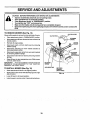
TO REMOVE MOWER (See Fig. 16)
Place attachment clutch in "DISENGAGED" position.
Move attachment lift leverforward to lowermowerto its
lowest position.
•
Roll belt off engine pulley,
•
Disconnect clutch rod from clutch lever by removing
retainer spring,
•
Disconnect anti-sway bar from chassis bracket by
removing retainer spring.
Disconnectsuspension arms from rear deck brackets
by removing retainer spdngs.
Disconnectfront linksfrom deck by removingretainer
springs.
•
•
ENGINE
RETAINER
SPRING
ANTI-SWAY BAR
TO INSTALL MOWER (See Fig. 16)
Slide mower undertractorwith
side of tractor.
•
•
Lower lift lever to its lowest position.
Install mower in reverse order of removal instructions.
I
SPRINGS
SLOES)
Raise lift lever to raise suspension arms. Slide mower
out from under tractor.
IMPORTANT:
IF AN ATTACHMENT OTHER THAN THE
MOWER IS TO BE MOUNTED TO THE TRACTOR,
REMOVED THE FRONT LINKS.
•
II
RETAINER
•
Raise attachment lift lever to its highest position.
I
CLUTCH
SUSPENSION
ARMS
•
Ill
CLUTCH LEVER
Mowerwill be easierto remove from the right sideoftractor.
•
•
i ,,,,,,
discharge guard to right
RETAINER
SPRINGS
(BOTH SIDES)
FIG. 16
19
AND ADJUSTMENTS
,,,,,,,,,,,,,,,,,,,
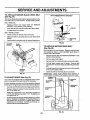
TO LEVEL MOWER HOUSING
FRONT-TO-BACK ADJUSTMENT (See Figs. 19 and 20)
IMPORTANT: DECK MUST BE LEVEL SIDE-TO-SIDE. IF
THE FOLLOWING FRONT-TO-BACK ADJUSTMENT IS
NECESSARY, BE SURE TO ADJUST BOTH FRONT LINKS
EQUALLY SO MOWER WILL STAY LEVEL SIDE-TOSIDE.
Adjust the mower whiletractor is parked on level ground or
driveway. Make sure tires are properly inflated (See
"PRODUCT SPECIFICATIONS" on page 3 of this manual).
If tires are over or underinflated, you will not properly adjust
your mower.
To obtain the best cutting results, the mower housing
should be adjusted so that the front is approximately 1/4" to
3/4" lower than the rear when the mower is in its highest
position.
SIDE-TO-SIDE ADJUSTMENT (See Figs. 17 and 18)
,
Raise mower to its highest position.
°
At the midpoint of both sides of mower, measure height
from bottom edge of mower to ground. Distance "A" on
both sides of mower should be the same or within 1/4"
of each other.
•
If adjustment is necessary, make adjustment on one
side of mower only.
•
To raise one side of mower, tighten lift link adjustment
nut on that side.
•
To lower one side of mower, loosen lift link adjustment
nut on that side.
°
NOTE: Each full turn of adjustment nut will change mower
height about 1/8".
•
o
•
Check adjustment on right side of tractor. Measure distance"D" directly in front and behind the mandrel at bottom
edge of mower housing as shown.
•
Before making any necessary adjustments, check that
both front links are equal in length. Both links should be
approximately 10-3/8".
Recheck measurements after adjusting.
BOTTOM EDGE
OF MOWER TO
............................................
°
BOTTOM EDGE
OF MOWER TO
•
•
If links are not equal in length, adjust one link to same
length as other link.
To lower front of mower loosen nut "E" on both front
links an equal number of turns.
When distance "D _ is 1/4" to 3/4" lower at front than
rear, tighten nuts "F" against trunnion on both front
links.
To raise front of mower, loosen nut"F" from trunnion on
both front links. Tighten nut "E" on both front links an
equal number of turns.
When distance "D" is 1/4" to 3/4" lower at front than
rear, tighten nut"F" against trunnion on both front links.
Recheck side-to-side adjustment.
MANDREL
GROUND LINE
FIG. 17
(_
SUSPENSION
FIG. 19
BOTHFRONT LINKS MUST BE EQUAL IN LENGTH
LIFT LINK
ADJUSTMENT NUT
FIG. 18
FRONT LINKS
2O
TRUNNION
FIG. 20
ICE AND ADJUSTMENTS
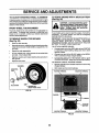
TO REPLACE
(See Fig. 21)
MOWER
BLADE DRIVE BELT
WITH PARKING BRAKE "ENGAGED"
The mower blade drive belt may be replaced withouttools.
Park the tractor on level surface. Engage parking brake.
BELT REMOVAL •
Remove mower from tractor (See "TO REMOVE
MOWER" in this section of this manual).
•
•
Work belt off both mandrel pulleys and idler pulleys,
Pull belt away from mower.
NUT "A"
JAM NUT
BELT INSTALLATION •
Install new belt in reverse order of removal.
•
•
Make sure belt is in all pulley groovesand inside all belt
guides.
Install mower in reverse order of removal instructions.
OPERATING
ARM
FIG. 22
MANDREL
PULLEY
IDLER
PULLEYS
TO REPLACE MOTION DRIVE BELT
(See Fig. 23)
Park the tractor on level surface. Engage parking brake.
For assistance, there is a belt installation guide decal on
bottom side of left footrest.
•
Remove mower (See "TO REMOVE MOWER" in this
section of this manual.)
•
•
Remove upper belt keeper.
Remove belt from stationary idler and clutching idler.
•
•
MANDREL
PULLEY
•
Install new belt by reversing above procedure.
IMPORTANT: MAKE SURE UPPER BELT KEEPER _S
POSITIONED PROPERLY BETWEEN LOCATOR TABS.
FIG. 21
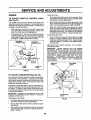
TO ADJUST
"
Pull beit slack toward rear of tractor. Remove belt
upwards from transaxte pulley by deflecting belt keepers.
Pullbelttoward front oftractor and remove downwards
from around engine pulley.
[
BRAKE (See Fig. 22)
Your tractor is equipped with an adjustable brake system
which is mounted on the right side of the transaxle.
/
CLUTCNING-.....IL---'_._---"'_ll
If tractor requires more than six (6) feet stoppingdistance
at highspeed in highest gear, then brake mustbe adjusted.
I
II
1,°LER
/
•
=
Depressdutch/brakepeda_andengage
parking brake.
Measure distance between brake operating arm and
nut "A" on brake rod.
•
If distance is other than 1-1/2", loosen jam nut and turn
nut "A" until distance becomes I-1/2". Retighten jam
nut against nut "A".
•
Road test tractorfor proper stopping distance as stated
above. Readjust if nec_essary. If stopping distance is:_
still greater than six (6) feet in highest gear, furthermaintenance is necessary. Contact your nearest authorized service center/department.
_
1 STATIONARY"'-II
/ TRANSAXLE_. I1
21
/! uLLEY
.
l 'l]
_-tL°J) |
"-=1 !
! i
_
FIG. 23
TABS
]
I
I r_ UPPER
BELT I
II
!1
II
KEEPER
i :t!1
I
!
I
l
SERVICE AND ADJUSTMENTS
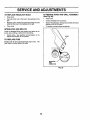
TO START ENGINE WITH A WEAK BATTERY
(See Fig. 25)
TO ADJUST STEERING WHEEL ALIGNMENT
tf steering wheel crossbars are not horizontal(leftto right)
when wheels are positioned straightforward, remove steering wheel and reassemble per instructions in the Assembly
section of this manual.
_
FRONT WHEEL TOE-IN/CAMBER
The front wheel toe-in and camber are not adjustable on
your tractor. If damage has occurred to affect the front
wheel toe-in or camber, contact your nearest authorized
service center/department.
(See Fig. 24)
Block up axle securely.
•
Removeaxlecover, retaining ring andwashersto allow
wheel removal (rear wheel contains a square key - Do
not lose).
Repair tire and reassemble.
°
u
On rear wheels only: align grooves in rear wheel hub
and axle. Insert square key.
°
Replace washers and snap retaining ring securely in
axle groove.
Replace axle cover.
TO ATTACH JUMPER CABLES •
Connect each end of the RED cable to the POSITIVE
(+) terminal of each battery, taking care not to short
against chassis.
•
Connect one end of the BLACK cable to the NEGATIVE (-) terminal of fully charged battery.
•
Connect the other end of the BLACK cable to good
CHASSIS GROUND, away from fuel tank and battery.
TO REMOVE CABLES, REVERSE ORDER •
WASHERS
•
RETAINING
RING
BLACK cable first from chassis and then from the fully
charged battery.
RED cable last from both batteries.
POSITIVE TERMINAL
NEGATIVE TERMINAL
!
AXLE COVER
_
SQUARE KEY
(REAR WHEEL ONLY)
FIG. 24
CABLES
CHARGED
BATTERY
POSITIVE TERMINAL
NEGATIVE TERMINAL
FIG. 25
•
!
if your battery is too weak to start the engine, it should be
recharged.
If "jumper cables" are used for emergency
starting, follow this procedure:
IMPORTANT: YOUR TRACTOR IS EQUIPPED WITH A 12
VOLT NEGATIVE GROUNDED SYSTEM.
THE OTHER
VEHICLE
MUST ALSO BE A 12 VOLT NEGATIVE
GROUNDED SYSTEM. DO NOT USE YOUR TRACTOR
BATTERY TO START OTHER VEHICLES.
TO REMOVE WHEEL FOR REPAIRS
•
ate explosivegases. Keep sparks,flame
and smoking materials away from batteries.
Always
wear batteries
eye protection
AUTION:
Lead-acid
generwhen around batteries.
22
IM,,,
|l
•
,,,,,II,,,,
II
I
I,,,,,IH
IIII"1111
I,,,I
""IIIIHIIIIIIIIIIIII
SERVICE AND ADJUSTMENTS
i
iiiiiiiiiiii
I
i
TO REPLACE
•
°
°
°
iiii ii iiiiiiiiiiiiiiiiiiiiiiii
HEADLIGHT
•
iiiiiiiiiiiwii
i
iiiiiiiiiiiiiiiiiiiiiiiii
TO REMOVE
BULB
i i ii
HOOD
II
AND
GRILL
Raise hood.
•
•
Unsnap headlight wire connector.
Stand in frontoftractor. Grasp hoodat sides,tilt toward
engine and lift off of tractor.
•
To replace, reverse above procedures.
AND RELAYS
Check wiring. See electrical wiring diagram in the
Repair Parts section of this manual.
TO REPLACE
ASSEMBLY
°
Loose or damaged wiring may cause your tractor to run
poorly, stop running, or prevent it from starting.
•
iii
(SeeFig. 26)
Raise hood.
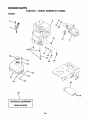
Pull bulb holder out of the hole in the backside of the
gdlL
Replace bulb in holder and push bulb holder securely
back into the hole in the backside of the grill.
Close hood.
INTERLOCKS
iii
HOOD
FUSE
Replace with 30 amp automotive-type plug-in fuse. The
fuse holder is located behind the dash.
HEADLIGHT
WIRE
CONNECTOR
FIG. 26
23
.................
_......
,,,,,,,,,
•
,,,
iiii
n
iiil,,,,,,,,i
III H,I
IIIIHII
I
I I,,,,,,
II
SERVICE AND ADJUSTMENTS
tllll
i
ENGINE
TO ADJUST THROTTLE
(See Fig. 27)
CONTROL
•
CABLE
•
, , ............................................................
Move throttle control lever to slow (,€_) position. With
finger, rotate and hold throttle lever against idlespeed
screw. Turn idle speed screw to attain 1750 RPM.
•
While still holding throttle lever against idle speed
screw, turn idle mixture valve in (clockwise) until engine begins to die and then turn out (counterclockwise)
until engine runs rough. Turn valve to a point midway
between those two positions. Release throttle lever.
ACCELERATION TEST -
With engine not running, move throttle control lever
from slow (-crab)to choke (k!) position. Slowly move
lever from choke (1",) to fast (_) position.
Checkthat holes"A" in governorcontrol leverand hole
in governor plate line-up. [f holes "A" are not aligned,
loosen clamp screw and move throttle cable until holes
are aligned. Tighten clamp screw securely.
GOVERNOR
CONTROL LEVER
, ,,,,,,,,,,,,,,,,,,,,,,
,,,
FINAL SE'I-I'ING •
Start engine and allow to warm for five minutes. Make
final adjustments with engine running and shift/motion
control lever in neutral (N) position.
The throttle control has been preset at the factory and
adjustment should not be necessary. Check adjustmentas
described below before loosening cable. If adjustment is
necessary, proceed as follows:
•
Hi
•
GOVERNOR
CONTROL PLATE
Move throttle control lever from slow (,g_) to fast (,e_)
position. If engine hesitates or dies, turn idle mixture
valve out (counterclockwise)
1/8turn. Repeattestand
continue to adjust, if necessary, until engine accelerates smoothly.
High speed stop is factory adjusted.
Do not adjust damage may result.
IMPORTANT:
NEVER TAMPER WITH THE ENGINE
GOVERNOR, WHICH IS FACTORY SET FOR PROPER
ENGINE SPEED. OVERSPEEDING THE ENGINE ABOVE
THE FACTORY
HIGH SPEED
SETTING
CAN BE
DANGEROUS.
IF YOU THINKTHE ENGINE-GOVERNED
HIGH SPEED NEEDS ADJUSTING,
CONTACT YOUR
NEAREST
AUTHORIZED
SERVICE
CENTER/
DEPARTMENT, WHICH HAS PROPER EQUIPMENT AND
EXPERIENCE
TO
MAKE
ANY
NECESSARY
ADJUSTMENTS.
HOLES "A"
CLAMP
SCREW
THROTTLE
CABLE
THROTTLE
tDLE SPEED
LEVER _
SCREW
FIG. 27
TO ADJUST CARBURETOR
(See Fig. 28)
The carburetor has been preset at the factory and adjustment should not be necessary. However, minor adjustmentmay be requiredtocompensate fordifferences in fuel,
temperature, altitude or load. If the carburetor does need
adjustment, proceed as follows:
In general, turning idle mixture valve in (clockwise) decreases the supply offuel to the engine givinga leanerfuel/
air mixture. Turning the idle mixture valve out (counterclockwise)increases the supply of fuel to the engine giving
a richer fuellair mixture.
IMPORTANT: DAMAGE TO THE NEEDLE VALVE AND
THE SEAT IN CARBURETOR MAY RESULT IF SCREW IS
TURNED IN TOO TIGHT.
IDLE MIXTURE
VALVE
PRELIMINARY SETTING=
•
Air cleaner assembly mustbe assembled tothe carburetor when making carburetor adjustments.
•
•
FIG. 28
Be sure the throttlecontrol cable is adjusted properly
(see above).
With engine off turn idle mixture valve in (clockwise)
closingit finger tight and then turn out (counterclockwise) 1 full turn.
24
IIIIIII IIIIII
IIIIIII I
I
II I
Jl_
I III
II II I
IU
I
STORAGE
ENGINE
Immediately prepare your tractorfor storage at the end of
the season or if the tractor wil! not be used for 30 days or
more.
I iiiii ii ii iiiiiiiiiiiiiiiiiiiii
IILII I
I
i
FUEL SYSTEM
I
IMPORTANT:
IT IS IMPORTANT TO PREVENT GUM
DEPOSITS
FROM FORMING
IN ESSENTIAL
FUEL
SYSTEM PARTS SUCH AS CARBURETOR, FUEL FILTER,
FUEL HOSE, OR TANK DURING STORAGE.
ALSO,
EXPERIENCE
INDICATES THAT ALCOHOL BLENDED
FUELS (CALLED GASOHOL OR USING ETHANOL OR
METHANOL) CAN ATTRACT MOISTURE WHICH LEADS
TO SEPARATION AND FORMATION OF ACIDS DURING
STORAGE.
ACIDIC GAS CAN DAMAGE THE FUEL
SYSTEM OF AN ENGINE WHILE IN STORAGE.
CAUTION: Never store the tractor with
gasoline in the tank inside a building
where fumes may reach an open flame
or spark. Allow the engine to cool
before storing in any enclosure.
IIII
IIIIII III
Rill
IIHI I
I
IlL
TRACTOR
Remove mower from tractor for winter storage. When
mower is to be stored for a period of time, clean it thoroughly, remove all dirt, grease, leaves, etc. Store in a
clean, dry area.
•
Clean entire tractor (See"CLEANING" in the Customer
Responsibilities sect on of this manual).
°
Inspect and replace belts, if necessary (See belt replacement instructions in the Service and Adjustments
section of this manual).
°
Lubricate as shown in the Customer Responsibilities
section of this manual.
°
Be sure that all nuts, bolts and screws are securely
fastened. Inspect moving parts for damage, breakage
and wear. Replace if necessary'.
•
Touch up al! rusted or chipped paint surfaces; sand
lightly before painting.
°
Start the engine and let it run until the fuel lines and
carburetor are empty.
Never use engine or carburetor cleaner products in the
fuel tank or permanent damage may occur.
Use fresh fuel next season.
NOTE: Fuel stabilizer is an acceptable alternative in
minimizing the formation of fuel gum deposits during storage. Add stabilizer to gasoline in fuel tank or storage
container. Always follow the mix ratio found on stabilizer
container. Run engine at least 10 minutes after adding
stabilizer to allow the stabilizer to reach the carburetor. Do
not drain the gas tank and carburetor if using fuet stabilizer.
ENGINE OIL
Drain oil (with engine warm) and replace with clean engine
oil. (See "ENGINE" in the Customer Responsibilities
section of this manual).
BAI-rERY
•
Fully charge the battery for storage.
•
After a pedod of time in storage, battery may require
recharging.
•
•
Drain the fuel tank.
CYLINDERS
To help prevent corrosion and power leakage during
long periods of storage, battery cabtes should be
disconnected and battery cleaned thoroughly (see'q'O
CLEAN BATI'ERY AND TERMINALS" in the Customer Responsibilities section of this manual).
After cleaning, leave cables disconnected and place
cables where they cannot come in contact with battery
terminals.
o
Remove spark plug(s).
•
Pour one ounce of oil through spark plug hole(s) into
cylinder(s).
Turn ignitionkeyto"START" positionfor a few seconds
to distributeoil.
•
•
Replace with new spark plug(s).
OTHER
•
Be sure battery drain tube is securely attached.
•
°
If battery is removed from tractor for storage, do not
store battery directly on concrete or damp surfaces.
•
Do not store gasoline from one season to another.
Replace your gasoline can if your can starts to rust.
Rust and/or dirt in your gasoline will cause problems.
°
If possible, store your tractor indoors and cover it to
give protectionfrom dust and dirt.
•
Cover yourtractorwith a suitable protective cover that
does not retain moisture. Do not use plastic. Plastic
cannot breathe which allows condensationto form and
will cause your tractor to rust.
IMPORTANT: NEVER COVER TRACTOR WHILE ENGINE
AND EXHAUST AREAS ARE STILL WARM,
25
i,i
i
i1|
iiiii1,,,,,,,,,
IHI,IIIIIIII
I
I I
I
I IIl,,,I,IIIIIIIIIIIIIIII
TROUBLESHOOTING
PROBLEM
I
POINTS
CORRECTION
CAUSE
===,m
Will not start
2.
3.
4.
5.
6.
7.
Out of fuel,
Engine not "CHOKED" properly.
Engine flooded.
Bad spark plug,
Dirty air tilter.
Dirty fuel filter.
Water in fuel.
1.
2.
3.
4.
5.
6.
7.
8.
9.
Loose or damaged wiring.
Carburetor out of adjustment.
8.
9.
1,
10.
Engine valves out of adjustment.
i
Hard to start
Engine will not turn over
i
m
10,
Fill fuel tank,
See "TO START ENGINE" in Operation section.
Wait several minutes before attempting to start,
Replace spark plug.
Clean/replace air filter.
Replace fuel filter.
Drain fuel tank and carburetor, refill tank with fresh
gasoline and replace fuel fitter.
Check all wiring.
See "To Adjust Carburetor" in Service Adjustments
section.
Contact an authorized service centertdepartment,
ii,,,,,,,m
1.
2.
3.
4.
5.
6.
7.
Dirty air flffer.
Bad spark plug,
Weak or dead battery.
Dirty fuel filter.
Stale or dirty fuel
Loose or damaged wiring.
Carburetor out of adjustment.
1.
2.
3,
4.
5.
6.
7.
8.
Engine valves out of adjustment.
8.
Clean/replace air filter.
Replace spark plug,
Recharge or replace battery.
Replace fuel filter.
Drain fuel tank and refill with fresh gasoline.
Check all wiring.
See "To Adjust Carburetor" in Sewice Adjustments
section.
Contact an authorized service center/department.
1.
2.
3.
4.
5.
6.
7.
8,
9.
Clutch/brake pedal not depressed.
Attachment clutch is engaged.
Weak or dead battery,
Blown fuse.
Corroded batteryterminals.
Loose or damaged widng.
Faulty ignition switch.
Faulty solenoid or starter.
Faulty operator presence switch{as).
t.
2,
3.
4.
5,
6.
7.
8.
9.
Depress clutch/brake pedal.
Disengage attachment clutch.
Recharge or replace battery,
Replace fuse.
Clean battery terminals.
Check all widng.
Check/replace ignition switch,
Check/replace solenoid or starter.
Contact an authorized service center/department,
1.
2.
3.
4.
_/eak or dead battery.
Corroded battery terminals.
Loose or damaged widng.
Faulty solenoid or starter.
1. Rechargeorreplace battery.
2. Cleanbattery
terminals.
3. Checkall wiring.
4. Checldraplacesolenotdor starter.
1.
2.
3.
4.
5.
6.
7.
8.
9.
Cutting too much grass/too fast.
Throttle in =CHOKE" position.
Build-up of grass, leaves and trash under mower.
Dirty air filter.
Low oil leve!/dirty oil.
Faulty spark plug.
Dirty fuel filter.
Stale or dirty fuel.
Water in fuel.
t.
2.
3.
4.
5.
6.
7.
8.
9.
ii
Engine clicks but will not
start
ii
Loss of power
iii
10.
11.
12.
13.
14.
Spark plug wire loose.
Dirty engine air screen/fins.
Dlrtylclogged muffler.
Loose or damaged wiring.
Carburetor out of adjustment.
10.
11.
12.
13.
14.
15.
Engine valves out of adjustment.
15.
°
Set in "Higher Cut" position/reduce speed.
Adjust throttle control.
Clean underside of mower housing.
Clean!replace air filter.
Check oil leve!tchange oil.
Clean and regap or change spark plug.
Replace fuel filter.
Drain fuel tank and refill with fresh gasoline.
Drain fuel tank and carburetor, refill tank with fresh
gasoline and replace fuel filter.
Connect and tighten spark plug wire.
Clean engine air screenlfins.
Clean/replace muffler.
Check all wiring.
See "To Adjust Carburetor" in Service Adjustments
section.
Contact an authorized service centeddeparlrnent.
m
Excessive vibration
1.
2.
3.
Worn, bent or loose blade.
Bent blade mandrel.
Loose/damaged part(s).
1.
2.
3.
26
Replace blade. Tighten blade bolt.
Replace blade mandrel,
Tighten loose part(s). Replace damaged parts.
III ,,,
TROUBLESHOOTING
POINTS
CAUSE
PROBLEM
I IIIIIIIIIII I I
CORRECTION
II
I
IIIIIIIIIII
I
I
II IIIIIIIIIIII
I
IIIIIIIIIIIIIIIIIIIII
II
Engine continues to run
when operator leaves seat
with attachment clutch
engaged
_.
Faulty operator-safety presence control system,
1.
Check wiring, switches and connections. If not
corrected, contact an authorized service center!
department.
Poor cut - uneven
1.
2.
3.
4,
5.
Worn, bent or loose blade.
Mower deck not level,
Buildup of grass, leaves, and trash under mower.
Bent blade mandrel.
Clogged mower deck vent holes from buildup of
grass, leaves, and trash around mandrels.
1.
2.
Replace blade. Tighten blade bolt.
Level mower deck.
3.
4.
5.
Clean underside of mower housing.
RepTace blade mandrel.
Clean around mandrels to open vent holes.
I.
2.
3.
4.
Obstruction in clutch mechanism.
Worn/damaged mower drive belt.
Frozen idler pufiey.
Frozen blade mandrel.
1.
Remove obstruction.
2.
3.
4.
Replace mower drive belt.
Replace idler pulley.
Replace blade mandrel.
Ill
Mower blades will not
rotate
IL ii
iiiiii
1.
2.
3.
4.
5.
6.
7.
8.
9.
10.
11.
Poor grass discharge
Headlight(s) not working
(if so equipped)
]l
Engine speed too slow.
Travel speed too fast,
Wet grass.
Mower deck not level.
Low!uneven tire air pressure.
Worn, bent or loose blade.
Buildup of grass, leaves and trash under mower.
Mower drive belt worn,
Blades improperly installed.
improper blades used.
Clogged mower deck vent holes from buildup of
grass, leaves, and trash around mandrels.
1.
2.
3,
4.
5.
6.
7.
8.
9,
t0,
ii1.
1.
2.
3.
4.
5.
Switch is "OFF".
Bulb(s) burned out.
Faulty light sw]tch.
Loose or damaged wiring.
Blown fuse.
1.
2.
3.
4.
5.
Turn switch "ON".
Replace bulb(s).
Checkfreplace light switch.
Check wiring and connections.
Replace fuse.
1.
2.
3.
4.
Bad battery cell(s).
Poor cable connections.
Faulty regulator (if so equipped).
Faulty alternator.
1.
2.
3.
4.
Replace battery.
ChecWcTeanall connections.
Replace regulator.
Replace alternator.
IH
Battery will not charge
ii
Engine "backfires"
when turning engine
"OFF"
Place throttJecontrol in "FAST" position,
Shift to slower speed.
Allow grass to dry before mowing.
Level mower deck.
Check tires for proper air pressure.
Replace/sharpen blade. Tighten blade bolt,
Clean underside of mower housing.
Replace mower drive belt,
Reinstall blades sharp edge down.
Replace with blades listed in this manual.
Clean around mandrels to open vent holes.
1,
Engine throttle control not set at "SLOW"
position for 30 seconds before stoppingengine.
27
1.
i
u
Move throttle control to "SLOW" position and allow
to idle for 30 seconds before stopping engine.
28
TRACTOR - - MODEL NUMBER 917.259290
SCHEMATIC
RED
BLACK
BATTERY
I
RED
!
RED
FUSE 30 AMP.
AMMETER
I
1
WHITE
'0
t
STARTER
1
8LACK L&
5F
I
' 0 '
......
J
SOLENOID
e
)G
-/
CLUTCH/ BRAKE
(PEDAL UP)
WHll_
IGNITION SWITCH
SEAT SWITCH
(NOT OCCUPIED)
!
WHITE
1
BLACK
--
1
-- I
I
,,t......
I
i
I
I
I
7
....
I.--
BLACK
A"rTrMENT CLUTGH"'_
(CLUTCH OFF)
I
GROUNDING
CONNECTOR
i
i
0
SLACK
PLUG
.____<_SPARK
IGNITION
UNIT
CHARGING SYSTEM OUTPUT
3 AMP DC @ 3600 RPM
28 VOLTS AC M1N, @ 3600 RPM
(CHARGING SYSTEM DISCONNECTED)
RED
LIGHTINGSYSTEM
OUTPUT
DIODE
5 AMP AC @_
NOTE
1_
,,.-,,.--.., ,t,._ ,.,,=-P,-.
,,_.,.,,,.,-P.,,-,,
_-, ,,.,._
YuuPt/H_L,/UH
l_
EQUIPPED WITH A SPECIAL
ALTERNATOR SYSTEM.
THE LIGHTS ARE NOT
CONNECTED
TOTHE
J'_
];_
p
I i ......
_
t
,ALTERNATOR
I
-_
""
"14
1
__
J
VOLTS AO MIN. @ 3600 RPM {LIGHTS
OFF)
HEADLIGHTS
.._-..
vT
Tv
BA'I-fERY, BUT HAVE THE1R
14E-AD£1G}_
I
_
]
OWN ELECTRICAL SOURCE.
SWITCH "
1--"-{{_
BECAUSE OF THIS, THE
(OFF)
BRIGHTNESS OF THE LIGHTS
IGNITION SWITCH
WILL CHANGE WITH ENGINE
POSITION
CIRCUIT
SPEED. AT IDLE THE LIGHTS
WILL DIM. AS THE ENGINE IS
WIRING INSULATED CLIPS
_ -7
OFF
M + G
SPEEDED UP, THE LIGHTS
ON
- B+ L
NOTE:
IF
WIRING
INSULATED
WILL BECOME THEIR BRIGHTEST.
START
B+ S+ L
CLIPS WERE REMOVED FOR
SERVICING OF UNIT, THEY
SHOULD BE REPLACED TO
NON-REMOVABLE
_
REMOVABLE
PROPERLY SECURE YOUR WIRING.
CONNECTIONS
CONNECTIONS
29
REPAIR PARTS
TRACTOR - - MODEL NUMBER 917,259290
ELECTRICAL
22
21
\
/
26
4O
42
36 38
34
]
/
I
32
/
/
!
31
3O
I
15
/
I
I
I
I
\
\
\
I
x
I
t
I
I
I
!
,4 6
_J
/
I
2
1
3O
REPAIR PARTS
TRACTOR - - MODEL NUMBER 917.259290
ELECTRICAL
KEY
NO.
PART
NO.
1 146139
2 74760412
3 STD551025
4 STD551125
6 STD541025
7 109238X
8 144940
9 109596X
15 147688
16 153664
19 STD551125
20 73350400
21 136850
22 4152J
24 4799J
25 146147
26 108824X
28 4207J
29 121305X
30 144921
31 140400
32 141226
33 140403
34 110712X
36 STD601005
38 140336
39 109553X
4O 146057
41 71110408
42 131563
43 145673
44 73640400
45 121433X
49 153249
7O 140413
DESCRIPTION
Batte[y 12 Volt 25 AMP
Bolt Hex Hd 1/4-20unc X 3/4
Washer 9/32 X 5/8 X 16 Ga
Washer Lock Hvy Helicat 1/4
Nut Fin Hex 1/4-20 Unc
Tube Plastic 12"
Case Battery
Clamp Hose Olive
Fastner Snap-In
Switch Interlock Push-In
Washer Lock 1/4
Nut Jam He)( 1/4-20 Unc
Harness Socket Light Wi4152J
Bulb Light #1156
Cable Battery 6ga 11" red
Cable Battery 6 Ga W/16 Wir red
Fuse 30 AMP Auto Green
Cable Ground 6ga 12" black
Switch Plunger Nc Gray
Switch lgn 3 pos
Nut Ignition
Cover Sw Ignition
Key ign Molded Craftsman, Delta
Switch Light Blk BIk Red
Screw Tap Hex #10-24unc X 1/2
Bracket Switch Interlock
Switch intlk CI MWR Gry 4 Term
Harness Ign Dash LT 1 PC Mech 95
Bolt BIk Hex 1/4-20unc x 1/2
Cover Terminal Red
Solenoid
Nut Keps Blk Hex 1/4-20 Unc
Ammeter Rectangular 6 AMP
Washer Pinned Delta
Harness Engine, B&S/Tec, Dual
NOTE: Atl component dimensions
1 inch = 25.4 mm
31
given
in U.S. inches
REPAIR PARTS
TRACTOR - - MODEL NUMBER 917.259290
CHASSIS AND ENCLOSURES
3O
24
17
i
26
26
25
18
I
I
29
14
19
140
28
26
13
33
10
38
34
26
14
32
REPAIR PARTS
TRACTOR
CHASSIS
- - MODEL
NUMBER
917.259290
AND ENCLOSURES
KEY
NO.
1
2
3
4
5
6
7
8
9
10
11
13
14
15
16
17
18
19
21
22
24
25
26
27
28
29
30
31
33
34
35
38
39
60
100
140
141
--
PART
NO.
151169
140356
17490612
STD551025
146077
!45208X013
126842X
126471X
146760X011
STD533710
146956
146961X012
17490608
74180512
STD541431
154988X574
126938X
17521312
122933X
124479X
STD523710
19131312
STD541437
170308t4
140137
124029X
109872X574
136619
145244X574
145243X574
STD533707
139886
139887
8TD533107
105037X
150556
73900600
5479J
DESCRIPTION
Chassis Wldmt 11ga
Drawbar Stretch
Screw Thdro! 3/8-16 x 3/4 Ty4t
Washer 13/32 X 3/4 X 16 Ga
Bumper Snap-In
Saddle Slkscr Fit Sdl 65 P930
Shield Ht. Hood
Clip Insulator 406 Mtg Hole
Dash Stkscr 1-pc
Bolt Rdhd Sqnk 3/8-16unc X 1
Panel Dash LH
Panel Slkscr Dash RH
Screw Thdrol 3/8-16 x 1/2 Ty-tt
Screw Mach TRHD 5/16-18 unc x 3/4
Nut Keps 5/16-18 Unc
Hood Asm Pnt SJope Weld Ms-574
Bumper Hood
Screw Sltd Hex Hd WiPI Washer
Rivet Ratchet Nylon
Washer Nylon Blk 28 x 75 x 19
Bolt Fin Hex 3/8-16 unc x 1 Gr. 5
Washer 13/32 X 13/16 x 12 Ga
Nut Hex Lock W/Ins. 3/8-16 Unc
Screw Spiderloc Hex Hd #8 x 7/8
Grille Grey
Lens Headlight Bar Clear
Fender Pnt LT Wlo Shift
Bracket Fender Rep1109873x
Footrest Pnt Lh
Footrest Pnt Rh
Bolt Rdhd Sht Sqnk 3/8-16 x 3/4
Bracket Asm Pvt LH MWR Rear
Bracket Asm Pvt RH MWR Rear
Bolt Rdhd Sqnk 3/8-16unc X 3/4
Strip Foam 18"
Bracket Chassis Front
Nut Lock Fig 3/8-16 Unc
Plug Button BIk 359 Dia Choke
NOTE: AU component dimensions given in U.S. inche
1 inch = 25.4 mm
,.
33
REPAIR PARTS
TRACTOR - - MODEL NUMBER 917.259290
DRIVE
51
5
18
6
6
32
52
77
35
o
36
34
25
19
_
36
">
i
74
22
34
26
27
3
REPAIR PARTS
TRACTOR
- - MODEL
NUMBER
917.259290
DRIVE
KEY
NO,
1
2
3
4
5
6
7
8
10
11
12
13
14
15
18
19
21
22
24
25
26
27
28
29
30
31
32
34
35
36
37
38
39
40
41
PART
NO.
.......
146682
123666X
12000028
121520X
17490512
130802
131679
STD561210
105701X
19151216
74550412
STD551125
74490544
STD523710
STD541437
106933X
130804
STD541237
106888X
STD551037
STD561210
145204
124236X
130807
127275X
STD523107
155071
120183X
STD551062
1572H
123674X
STD523727
4470J
153399
KEY
NO.
DESCRIPTION
PART
NO.
DESCRIPTION
Washer 13/32 X 13/16 X 12 Ga
42 19131312
44 105706X
Bearing Nyl 503 X 628 X 1 25
Washer Hardened
45 110812X
Ring Klip #t5304-50
46 12000039
Pulley Idler V Groove Plastic
47 127783
Bellcrank Asm Clutch
48 123789X
49 123205X
Retainer Belt Style Spring
Bolt Hex Hd 3/8-16unc X 1-1/2
50 STD523715
Nut Crownlock 3/8-16 UNC
51 STD541437
Nut Crown Lock 5/16-18
52 STD541431
Link Clutch 7 66
53 105710X
Fuel Line 13/32 Mtg Hole
54 2751R
55 105709X
Spring Return Clutch 6 75
Bolt Fin Hex 3/8-16 unc x 1-1/4
56 STD523712
V-Belt Gd Drive 95 25
57 t30801
58 127274X
Keeper Belt RH LT Pnt/zinc 16g
59 140312
Keeper Belt Centerspan
61 17490612
Screw Thdrol 3/8-16x3/4 Ty-tt
Cover Pedal Blk Round
62 8883R
63 140186
Pulley Eng CI Mech 38deg LT/YT
Bolt Hex 7/16-20x4 Gr 5
64 71170764
65 STD551143
Washer Lock Hvy Hlcl Spr 7/16
66 156053
Keeper Belt Engine Fool-Proof
Guide Belt Mower Drive RH
70 134683
Washer 13/32 X 1-1/4 X 12 Ga
72 19132012
Spacer Axle
74 137057
Washer 25/32 X 1 1/4 X 16 Ga
75 121749X
76 STD581075
E-ring #5133-75
77 123583X
Key Square 2 0 X 1845/1865
Washer 25/32 X 1-5/8 X 16ga
78 121748X
79 2228M
Key Woodruff #9 3/16 x 3/4
96 STD624003
Retainer Spring
Washer 9/32 X 3/4 X 10 Ga
112 19091210
113 127285X
Strap Torque Lt
Bolt Rdhd Sq Neck 3/8-16 x 1.25
116 72110610
NOTE: All component dimensions given in U.S. inches.
1 inch = 25.4 mm
Transaxle (See Breakdown)
.Peerless Model 930-055A
Spring Return Brake T/a Zinc
Pulley Transaxle t8/20" tires
Ring Retainer # 5100-62
Strap Torque 30 Degrees
Screw Thdrol 5/16-18 X 3/4 TYT
Bracket Saddle Shift T/a
Rod Shf Sdl LY/YT Str BIk Zinc
Pin Cotter 1/8 X 1 Cad
Washer Plate Shf 388 Sq Hole
Washer 15/32 X 3/4 X 16ga
Bolt 1/4-28unf Gr8 W/Patch
Washer Lock Hvy Helical 1/4
Bolt Hex FLGHD5/16-18Gr.5
Bolt Fin Hex 3/8-16unc X 1 Gr. 5
Nut Lock Hex W/Ins. 3/8-16 Unc
Knob Rd 1/2-13 Plstc Thds BIk
Rod Brake BIk Zinc 26 840
Nut Hex Jam 3/8-16 Unc
Spring Rod Brake 2 00 Zinc
Washer 13/32 X 13/16 X 16 Ga
Pin Cotter 1/8 X 3/4 Cad
Rod Brake Parking Lt/Yt
Cap Brake Parking Red
Bracket Mtg Transaxle
Keeper Belt LH LT 14 Ga
Bolt Hex Hd 5/16-18unc X 3/4
Shaft Asm Pedal Foot
Bearing Nylon BIk 629 Id
Washer 21/32 X 1 X 16 Ga
Pin Roll 3116 X 1"
Pulley idler Flat
Bolt Fin Hex 3/8-16unc X 2-3/4
Spacer Split 395 X 59 Bzp
Keeper Belt Idler
35
REPAIR PARTS
TRACTOR -- MODEL NUMBER 917.259290
STEERING
ASSEMBLY
".'..-..'-J.--/__
t
62
67
58
4O
25
36
13
REPAIR PARTS
TRACTOR
STEERING
-- MODEL
NUMBER
917.259290
ASSEMBLY
KEY
NO.
1
2
3
4
5
6
7
8
9
10
11
12
13
14
15
16
17
18
19
20
21
22
23
24
25
26
27
28
29
3O
32
36
37
38
39
40
41
42
43
46
47
62
65
66
67
68
PART
NO.
139768
142033
135227
135228
6266H
121748X
19272016
12000029
3366R
130468
STD551137
73610600
110438X
74011056
73901000
132624
132614
57079
124035X
126684X
STD551125
71100410
1275O1
109816X
124036X
126847X
136874
19131416
17490612
STD561210
130465
155099
152927
139769
19133808
STD541537
104820X
124417X
121749X
121232X
6855M
149684
154780
154404
74781O44
154429
DESCRIPTION
Wheel Steering Opp Sears BIk
Axle Asm Front Lt
Spindle Asm Lh
indle Asm Rh
sher Thrust .75 x 1.230
Washer 25/32 x 1-5/8 x 16 Ga.
Washer 27/32 x 1-1/4 x 16 Ga.
RingKlip #T5304-75
Bearing Col Strg Bik
Link Drag Sol Ball Jt 20.064
Washer Lock Hvy Hlcl Spr 3/8
Nut Fin Hex 3/8-24 Unf
Spacer Bearing Axle Front
Bolt, Hex 5/8-11 UNC x 3-1/2
Locknut Flange 5/8-11 UNC
Pin Axle 5/8 x 1,55/1.54 Lg
Shaft Asm Strg 5/8 x 15.19 Lt
Washer Th rust .515 x .750 x .033
Support Shaft
Washer Shim 1/4 x 5/8 x .062
Washer Lock Hvy Helical 1/4
Screw Cap Sckt Hd Phos & Oil
Shaft Asrn Pitman
Nyliner Snap In
Bracket Steering
Bushing Link Drag BIk LR
Gear Sector 22 Teeth
Washer 13/32 x 7/8 x 16 Ga.
Screw Thdrol 3/8-16 x 3/4 TY-'II"
Pin Cotter 1/8 x 3/4 Cad
Rod Tie Wire Form 19.75 Mech
Bushing Strg. 5/8 ID Dash
Screw
Cap Wheel Steer Opp Sears BIk
Washer 13/32 x 2-3/8 x 8 Ga.
Locknut Center 3/8-24 Unf
Adaptor Wheel Strg..640/.635 Id
Boot Shaft Steering Craftsman
Washer 25/32 x 1-1/4 x 16 Ga.
Cap Spindle Fr Top BIk
Fitting Grease
Steering Assembly
Spaccer Axle
Bearing Arm Pitman
Bolt Fin Hex 5/8-1 lunc x 3-3/4
Brace Axle
NOTE: All component dimensions
1 inch = 25.4 mm
37
given in U.S. inches
REPAIR PARTS
TRACTOR - - MODEL NUMBER 917,259290
ENGINE
81
4
23
29
OPTIONAL
EQUIPMENT
Spark Arrester
}
38
REPAIR PARTS
TRACTOR
- - MODEL
NUMBER
917.259290
ENGINE
KEY
NO.
1
2
PART
NO.
132759
17720410
........
4
13
14
15
16
23
29
31
32
33
35
37
38
137348
272293
13280324
13200300
STD551237
150554
137180
109202X
123549X
123487X
17490512
137040
.......
40
44
46
62
72
78
81
124028X
17490412
19091416
STD551131
71070512
1749062O,
128861
DESCRIPTION
Control Th/ch RH BIk Pdl 15 10
Screw Hex Thd Cut 1/4-20x518 T
Engine (See Engine Breakdown) B&S
Model No. 28R707-0148-01
Muffler LT B&S 12/12 5/13 HP
Gasket Eng 1 313 Id Tin Plated
Nipple Pipe 3/8 Npt x 3"
Elbow Std 90 Degree 3/8-18 Npt
Washer Lock Ext Tooth 3/8
Shield Browning
Kit Spark Arrestor (Flat Scrn)
Tank Fuel Front 1 25
Cap Asrn Fuel W/sym Vented
Clamp Hose Blk
Screw Thdrol 5/16-18 x 3/4
Line Fuel 20"
Plug Oil Drain (Order From Engine
Manufacturer)
Bushing Snap Nyl BIk Fuel Line
Screw Hexwsh Thdrol 1/4-20 x 3/4
Washer 9/32 x 7/8 x 16 ga
Washer Lock Hvy HIcl Spr 5/16
Screw Hex Hd Cap 5/16-18 X 3/4
Screw Thdrol 3/8-16x1-1/4 TYTT
Nut Flange 1/4-20 Starter Nut
NOTE: All component dimensions given in U,S. inches
1 inch = 25.4 mm
39
REPAIR PARTS
TRACTOR - - MODEL NUMBER 917.259290
SEAT ASSEMBLY
10
KEY
NO.
PART
NO.
1
2
3
4
5
6
7
8
9
10
12
13
140122
140551
STD523710
19131610
145006
STD541437
i24181X
17490616
19131614
155925
121246X
121248X
7----+
DESCRIPTION
Seat
Bracket Pvt St
Bolt Fin Hex 3/8-16unc X 1
Washer Flat 13/32 X 1 X 10 Ga
Clip Push-ln Hinged
Locknut Hex W/Wsh 3/8-16
Spring Seat Cprsn 2 250 BIk Zi
Screw Thdrol 3/8-16 X 1 Ty-tt
Washer 13/32 X 1 X 14 Ga
Pan Seat
Bracket Mounting Switch
Bushing Snap BIk Nyl 50 Id
KEY
NO.
PART
NO.
14
15
16
17
21
22
23
24
25
26
72050411
134300
121250X
123976X
153236
STD541431
74780814
19171912
127018X
STD551150
NOTE:
4O
DESCRIPTION
Bolt Rdhd Sht Nk 1/4-20xl-3/8
Spacer Split 28x 96 Yel Zinc
Spring Cprsn I 27 BIk Pnt
Nut Lock 1/4 Lge Fig Gr 5 Zinc
Bolt Shld 5/16-18 Unc-2A
Nut Lock Hex "W/Ins 5/16-18
Bolt Fin Hex 1/2-13 X 7/8 Gr5
Washer 17/32 X 1-3/16 X 12 Ga
Bolt Shoulder 5/16-18 X 62:
Washer Lock Hvy HIc! Spr 1/2
Allcomponent dimensions given in U.S. inches
1 inch = 25.4 mm
REPAIR PARTS
TRACTOR - - MODEL NUMBER 917.259290
DECALS
6
19
3
14
7
7
17
9
4
14
11
17
10
21
12
13
15
18
KEY
NO.
1
3
4
5
6
7
8
9
10
11
12
PART
NO,
138955
150676
150677
150680
133644
151799
140837
128314
149516
137537
4900J
KEY
NO.
DESCRIPTION
Decal Dash lnst Oper English
Decal Hood RH Crafts Sip LT
Decal Hood LH Crafts Sip LT
Decal GdIle Crafts
Decal Maint Cust Sears Domesti
Decal Side Pnl
Decal Brake Parking Saddle
Decal Fender Craftsman White
Decal Battery Dngr/Psn Eng Acme
Decal Caution Fender Eng/span
Decal Clutch!brake English
13
14
15
17
18
19
21
------
PART
NO.
146046
150678
136832
150679
133179
150333
131265
145245
138311
145247
156627
156628
DESCRIPTION
Decal V-Belt Dr Sch Tractor
Decal Chassis 6sp 42"
Decal V-Belt Sch
Decal Ins Hood
Decal Mower Qc System
Decal Cap CNSMR Help Line SRS
Decal Lightbox
Pad Footrest
Decal Handle Lft Height Adjust
Fastner Pop In Footrest
Manual Owners English
Manual Owners Spanish
WHEELS & TIRES
KEY
NO.
PART
NO.
DESCRIPTION
1 59192
Cap Valve Tire
2 65139
Stem Valve
3 106222X
Tire F Ts 15 X 6 0 - 6 Service
4 59904
Tube Front (Service Item Only)
5 106732X427
Rim Asm 6" front White Service
6 278H
Fitting Grease (Front Wheel Only)
7 9040H
Bearing Flange (Front Wheel Only)
8 106108X427
Rim Asrn 8" rear White Service
9 124635X
Tire R Ts 18x8 5-8 C Service
10 7152J
Tube Rear (Service item Only)
11 104757X
Cap Hub Axle Blk 1 50 X 1 00
- - 144334
Sealant, Tire (10 oz. Tube)
NOTE: Atl component dimensions given in U.S. inches
1 inch = 25.4 mm
4,10
7
41
REPAIR PARTS
TRACTOR-
- MODEL NUMBER 917.259290
LIFT
5
3
\
13
6
6
11
l
13
t
19
!
2O
15
.._
161718
20
20
i
42
,
REPAIR PARTS
TRACTOR-
- MODEL NUMBER 917.259290
LIFT
KEY
NO.
PART
NO.
1
2
3
4
5
6
7
8
10
11
12
13
15
16
17
18
19
20
31
32
136973
122507X
105767X
12000002
19211621
120183X
125631X
122365X
122512X
139865
139866
STD624008
127218
7335O800
130171
73800800
139868
STD624008
140302
73540600
DESCRIPTION
Wire Asm Inner W/plunger 17 32
Shaft Asm Lift 9 680
Pin Groove 1 500 Zinc
E Ring #5133-62
Washer Pltd 21/32 X 1 X 21ga
Bearing Nylon BIk 629 Id
Grip Handle Fluted BIk
Button Plunger Red
Spring Cprsn 3 750 Oiled
Link Lift LH
Link Lift RH
Retainer Spring
Link Front
Nut Jam Hex 1/2-13 Unc
Trunnion BIk Zinc
Nut Lock W/wsh 1/2-13unc
Arm Suspension Rear
Retainer Spring Zinc
Bearing Pvt Lift Spherical
Nut Crowniock 3/8-24
NOTE: All component dimensions given in U.S. inches
1 inch = 25.4 mm
43
REPAIR PARTS
TRACTOR
- - MODEL
NUMBER
917.259290
MOWER
76
77
74
52
33
32
31
16
27
29
,18
REPAIR PARTS
TRACTOR--
MODEL
NUMBER
917.259290
42" MOWER
KEY
NO.
PART
NO.
1
2
3
4
5
6
8
9
10
11
12
13
144393
STD533t07
138017
138440
STD624008
130832
850857
STD551137
140296
134149
129895
137645
14
15
16
17
18
19
20
21
22
23
24
25
26
27
28
29
30
31
32
33
34
35
36
37
40
41
43
44
128774
1t0485X
140329
72110610
72140505
132827
136888
STD541437
134753
131267
105304X
123713X
110452X
130968
19111016
131491
138776
129963
153535
137266
STD533717
133835
131494
STD551037
STD541437
133551
140083
140088
KEY
NO,
DESCRIPTION
PART
NO.
DESCRIPTION
Retainer
Screw, Thd. Roll 1/4-20 x 5/8
Washer, Hardened
Roller Assembly, Cam Follower
Bolt, Shoulder #10-24 Grade 5
Locknut
Bott, Shoulder 5/16-18 UNC
Arm Assembly, Pad, Brake
Washer, Hardened
Arm, Idler
Spacer, Retainer
Spring, Torsion Brakes 42
Guard, Tuv Idler (94)
Knob Custom Oval
V-Belt
Rod, Clutch, Primary, with Nibs
Spring, Return
Arm, Clutch, Secondary
Washer 25/32 x 1_5/8 x 16 Gauge
Ring, KIip
Bolt, Shoulder 3/8-16 UNC x 1.44
Keeper, Spring
Arm, Clutch, Primary
Bushing, Large, Brass
Spring, Mower Clutch
Nut, Hex Jam 3/8-16 UNC
Trunnion Adj. 94
Washer Sintered
Keeper Belt Idler Fixed
Bolt Carriage 3/8-16 x 2°1/4
Locknut, Hex W/Wsh 3/8-16 UNC
Washer Felt
Spacer Washer 13/32 I.D. X 1-3/8
O.D. x 1/4
Mandrel Assembly (Includes Key
- - t30794
Numbers 8-10, 12-15, 31 and 32)
-145411
Mower Deck, Complete
Available Mulcher Plate Kit not included with tractor:
- - 141112
Mutcher Close-out Plate Kit
Mower Housing
Bolt
Bracket Assembly,Sway Bar, Front
Bracket Assembly, Sway Bar
Retainer Spring
Arm, Suspension, Rear
Bolt, Hex 3/8-24 x 1.25 Grade 8
Washer, Lock
Washer, Hardened
Blade, Mulching
Bearing, Ball
Shaft Assembly, Mandrel, Vented
(Includes Key Number 6)
Housing, Mandrel, Vented
Bearing, Ball, Mandrel
Stripper, Vented Mower Deck
Bolt, Carriage 3/8-16 x 2-1/4
Bolt, Carriage 5/16-18 x 5/8
Bolt, Shoulder
Baffle, Vortex
Nut, Crownlock5/16-18 UNC
Stiffener Bracket
Bracket, Deflector
Cap, Sleeve
Spring, Torsion, Deflector
Nut, Push
Shield, Deflector
Washer 11/32 x 5/8 x 16 Gauge
Rod, Hinge
Screw Thdrol Hex Head Zinc Mwr
Washer, Spacer
Pulley, Mandrel
Nut, Toplock, Flanged
Bolt
Fastner, Christmas Tree
Pulley, Idler, Flat
Washer 13!32x13/16x16Ga.
Nut, Crownlock 3/8-16 UNC
Rod, Pivot, with Nibs
Rod, Clutch, Secondary, with Nibs
Guard, MandreJ, L.H.
45
46
48
49
50
51
52
53
54
55
56
58
59
67
68
71
72
73
74
75
76
77
78
79
80
8!
82
83
84
85
92
128
132
STD624003
137729
133944
133940
131340
STD541410
139888
131845X900
133943
140084
122052X
140086
141043
149846
144200
142427
131870
127847
121748X
12000029
128903
127845
140334
127498
153701
73350600
142028
120958X
144394
72140618
STD541437
153390
19132203
NOTE: All component dimensions given in U.S. inches
1 inch = 25.4 mm.
45
REPAIR PARTS
TRACTOR - - MODEL NUMBER 917.259290
PEERLESS
68
TRANSAXLE
- MODEL NUMBER 930-055A
34
/
7
67
/
9
77
31
35
76
5O
83
18
52
29
63
23
54
69
69
t50
i
/
9O
15
MODEL
NUMBERSHERE
46
6534
33
11
56
REPAIR PARTS
TRACTOR
PEERLESS
REF PART
NO. NO.
1
2
3
4
5
6
7
8
8A
9
10
11
12
13
14
15
17
18
20
21
22
23
25
772108A
780086
770102A
776260
776219B
778139
778136
792136A
792047
784352
784355
778229
778113A
778221
778068
778260
786139
786102
792077
792078
792079
788061
792073
26
792125
27
28
29
30
31
32
33
34
35
36
37
38
39
40
41
42
792035
788040
780072
780108
780001
792001
788095
780105A
780118A
790003
790007
799021
786026
792076A
790079
792073
42A 792085A
TRANSAXLE
- -MODEL
NUMBER
917.259290
- MODEL NUMBER 930-055A
REF PART
NO. NO.
DESCRIPTION
Cover, Transaxle
Bearing, Needle
Case, Transaxle
Shaft, Counter
Shaft and Pinion Assembly, Output
Gear, Output
Gear, Spur, 15 Teeth
Key, Shift
Key, Woodruff
Collar, Shifter
Rod and Fork Assembly, Shift
Gear, Bevel, 42 Teeth
Bevel Pinion, Input
Gear, Bevel
Gear, Bevel Pinion
Gear, Ring
Pin, Drive
Spacer, Neutral
Bali, Steel 5/t 6" diameter
Set Screw 3/8-16 x 3/8
Spring
Ring, Seal
Screw, Flanged Hex Head, Thread
Forming 1/4-20 x 1-1/4
Ring, Retainer
(4 Required, Package of 2)
Ring, Retainer
Ring, Retainer
Washer, Thrust
Washer, Thrust
Washer
"O" Ring
Seal, Square Cut
Bushing, Flanged
Bushing, Flanged
Disk, Brake
Plate, Brake Pad
Pad, Brake
Pin, Dowel
Washer, Flat
Lever, Brake
Screw, Flanged Hex Head, Thread
Forming 1/4-20 x 1-1/4
Screw 1/4-20 x 2-1/4
43
44
45
46
47
48
49
50
51
52
53
54
56
57
58
59
60
61
65
66
67
68
69
70
71
72
72A
76
77
792075
790025
786066
786086
774690
774691
778215
778125
778124A
778123A
778122A
778273
778230
778151
778126A
778127A
778128A
778163
780109
776135
776315A
786116A
780051
786118
788069
792165
788091
780090
788078A
79
8!
792144
786081
82
83
90
103
104
150
900
786082
786t23
788067B
792166
792167
510334
794603
DESCRIPTION
Locknut 5/16-24
Holder, Brake Pad
Spacer
Bracket, Brake Lever
Axle 11-5/16" long
Axle 16-1/2" long
Gear S )ur, 37 Teeth, Steel (1,,)
Gear S 3ur, 35 Teeth (2,.)
Gear S 3ur, 30 Teeth (34)
Gear S 3ur, 25 Teeth (44)
Gear S 3ur, 22 Teeth (5_)
Gear S )ur, 19 Teeth, Steel (6_)
Gear S3ur, 12 Teeth (1,,)
Gear S 3ur, 15 Teeth (2.,)
Gear S 3ur, 20 Teeth (3-)
Gear S )ur, 25 Teeth (4=)
Gear S }ur, 28 Teeth (54)
Gear. S )ur, 31 Teeth (6_)
Washer Thrust
Shaft, Input
Shaft, Brake, 4 Keyed
Plug
Washer, Thrust
Spacer
Seal, Square Cut
Plug, Threaded 9/16-18
"O" Ring
Washer, Thrust
Ring, Retaining, Inverted
(Package of 2)
Spring, Brake
,
Chain, Roller
(Number 41 Chain, 24 Links)
Sprocket, 9 Teeth (Reverse)
Sprocket, 18 Teeth (Reverse)
Grease, Bentonite, 32 Ounce Bottle
Screw 1/4-20 x 2
Locknut 1/4-20
Gasket Eliminator (Loctite #515)
Replacement Transaxle
NOTE: All component dimensions given in U.S. inches
1 inch = 25.4 mm
47
REPAIR PARTS
TRACTOR
BRIGGS
& STRATTON
ENGINE
11o19LABELK,T!
11058
OWNER'S
- - MODEL
- MODEL
NUMBER
NUMBER
917,259290
28R707,
TYPE
NUMBER
0148-01
552
MANUALI
230
87
306
8
308
lk REQUIRES SPECIAL TOOLS
TO INSTALL. SEE REPAIR
INSTRUCTION MANUAL.
337
761
!044 _
1045
48
REPAIR PARTS
TRACTOR -- MODEL NUMBER 917.259290
BRIGGS
& STRATTON
ENGINE
- MODEL
NUMBER
28R707,
TYPE
NUMBER
0148-01
618
52
k
50
i42
NOTE:SERVICES
BOTH
MANUALAND
REMOT£
CHOKECARBURETORS,
_105
123
_lr REQUIRES SPECIAL TOOLS
TO INSTALL. SEE REPAIR
INSTRUCTION MANUAL.
523
284
445 !4
I
171
524
4.:
535
49
REPAIR PARTS
TRACTOR - - MODEL NUMBER 917.259290
BRIGGS & STRA_ON
ENGINE - MODEL NUMBER 28R707, TYPE NUMBER
0148-01
240
_657
i87
.....
I
601'
216
877
_729
305
_ 78
1044
73
304
1006 _
i
851
100_
334
5O
_188
REPAIR PARTS
TRACTOR - - MODEL NUMBER 917.259290
BRIGGS & STRATTON
ENGINE - MODEL NUMBER 28R707, TYPE NUMBER
0148-01
801
783
729A
728
r_
615
1090
311
803
544
51
REPAIR PARTS
TRACTOR-BRIGGS & STRATTON
KEY PART
NO. NO.
1
2
3
4
5
7
8
9
10
11
12
496413
399265
391O86
494238
494240
94881
231109
271866
495735
27803
94621
280100
271916
271997
271996
13 94622
15 94239
16 495162
94196
20 291675
22 94624
23 492326
24 222698
25 394661
394662
394663
394664
26 391780
392331
391781
391782
391783
27 260924
28 299691
391286
29 490348
490469
32 94671
33 262246
34 262247
35 65906
36 26828
37 224502
40 221596
41 292260
42 494553
45 262248
46 212897
50 213819
51 272465
MODEL
NUMBER
917,259290
ENGINE - MODEL NUMBER 28R707, TYPE NUMBER
KEY PART
NO. NO.
DESCRIPTION
52 272554
53 94637
73 493439
75 225136
78 94822
87 491323
93 281346
94 498030
94A
494383
95 94O98
98 495800
104 231789
105 231855
106 231854
108 224540
108A 224558
121 497535
123 94913
125 498027
127
--130 224539
131 494379
133 494381
137 281165
138 281164
141 495931
141A 49438O
142 497566
497567
Cylinder Assembly
Bearing, Cylinder
* Seal, Oil
Base, Engine
Head, Cylinder
Screw, Hex (Qty. 1) (Key No. 305A)
, Spacer (Qty. 1) (Key No. 668A)
Gasket, Cylinder Head
Breather Assembly
(Includes Mounting Gasket)
* Gasket, Valve Cover
Screw, Sems
Tube, Breather
* Gasket, Crankcase Cover, 1/64"
* Gasket, Crankcase Cover, .005"
* Gasket, Crankcase Cover, .009"
Screw, Cylinder Head
Plug, Oil Drain
Crankshaft
Key, Timing Gear
* Seal, Oil
Screw, Sems, Base Mounting
Flywheel
Key, Flywheel
Piston Assembly, Standard Size
Piston Assembly, .010" Oversize
Piston Assembly, .020" Oversize
Piston Assembly, .030" Oversize
Ring Set, Standard Size
Ring Set, Standard Size, Chrome
Ring Set, .010" Oversize
Ring Set, .020" Oversize
Ring Set, .030" Oversize
Lock, Piston Pin
Pin, Piston, Standard Size
Pin, Piston, .005" Oversize
Rod, Connecting
Rod, Connecting, .020" Undersize
Screw, Connecting Rod
Valve, Exhaust
Valve, Intake
Spring, Valve
Spring, Valve
Guard, Flywheel
Retainer, Intake Valve
Rotocoil, Exhaust Valve
Retainer, Rotocoi!
Tappet, Valve
Gear, Cam
Carburetor, Elbow
*** Gasket, Carburetor
497736
497737
t47
499O95
498239
171
186
187
188
201
209
216
219
222
224
227
230
232
240
265
*
**
***
281051
494451
393815
94627
262767
260871
262766
490815
495611
94729
493935
94927
262785
394358
221535
0148-01
DESCRIPTION
* Gasket, Carburetor
Stud, Carburetor Mounting
Screen, Rotating
Washer, Spring
Screw, Torx_
* Seal, Governor
Bushing, Throttle Shaft
Valve, Needle
Valve, Needle
** Screw, Throttle
Screw, Idle Adjust
** Pin, Float Hinge
** Valve, Inlet Needle
** Seat, Inlet
Valve, Choke
Valve, Choke
Carburetor Kit
Screw, Elbow Mounting
Carburetor
** Plug, Welch (Sold in Kit Only)
Valve, Throttle
Shaft, Throttle
Float, Carburetor
*** Gasket, Float Bowl
*** Washer, Float Bowl
Shaft, Choke
Shaft, Choke
NozzIe, Carburetor
Nozzle, Carburetor (High Altitude)
Used on LMT 157
** Nozzle, Carburetor
Nozzle, Carburetor (High Altitude)
Used on LMT 96
Jet, Pilot
Used on LMT 157
** Jet, Pilot
Used on LMT 96
Nut, Air Cleaner
Elbow, Fuel Pipe
Line, Fuel (11" Long, Cut to Suit)
Screw, Sems
Link, Governor
Spring, Governor
Link, Choke
Gear, Governor
Plate, Governor Control
Screw, Hex Head
Lever Assembly, Governor
Washer, Governor Crank
Spring, Governor Link
Filter, Fuel
Clamp, Casing
Included in Gasket Set (494241)
Included in Carburetor Kit (497535)
Included in both Carburetor Kit (497535),
and Carburetor Gasket Set (494385)
NOTE: All component dimensions given in U.S. inches
1 inch = 25.4 mm
52
REPAIR PARTS
TRACTOR -- MODEL NUMBER 917.259290
BRIGGS & STRATTON
KEY PART
NO. NO.
284 94903
284A 94704
304 496280
305 94786
306 224545
307 94930
308 491490
309 497595
310 94003
311 497608
333 492341
334 194731
337 802592
346 94896
356 494328
358 494241
363 19203
383 89838
445 496894
467 493903
474 393474
482 93621
503 806000
510 497606
523 495230
524 281370
525 496113
535 272403
537 281106
544 497603
552 491986
562 94907
592 231978
601 93053
614 93306
615 263080
616 495157
618 262803
634 398970
634A 494453
634B 281168
635 66538
646 224546
657 94906
663 94929
ENGINE - MODEL NUMBER 28R707, TYPE NUMBER 0148-01
KEY PART
NO. NO.
DESCRIPTION
Screw, Shoulder
Screw, Hex Head
Housing, Blower
Screw, Hex Head
Shield, Cylinder
Screw, Sems
Cover, Cylinder Head
Motor, Starter
Thru Bolt
Brush Assembly
Armature, Magneto
Screw, Sems
Plug, Spark
Screw, Hex Head
Wire Assembly
Gasket Set
Puller, Flywheel
Wrench, Spark Plug
Cartridge, Air Cleaner
Knob, Air Cleaner
Stator, Alternator
Screw, Sems _
Strap, Starter
Starter Drive Group
Dipstick, Oil
* Seal, Oil
Tube, Oil Filler
Element, Filter
3
* O-Ring, Air Cleaner
Armature, Starter
Bushing, Governor Crank
Bolt, Governor Lever
Nut, Hex
Clamp, Fuel Pipe
Pin, Cotter
Retainer
Crank, Governor
Spring, Choke Return
** Washer, ThrottIe Shaft
* Seal, Spring Assembly
** Seal, Choke Shaft
Elbow, Spark Plug
Brace, Air Cleaner
Screw, Seres
Screw, Hex Head
726 392134
727 490324
728 94951
729 281159
729A 225170
741 262932
757 213998
758 399891
759 298909
761 94593
783 280104
801 394856
802 497605
803 497604
842 270920
847 496415
851 493880
869 261463
870 213316
871 261961
231218
872 281361
875 494237
877 393456
955 94642
965 94010
975 494378
977 494385
987 281166
1005 281400
1006 224413
1019 491252
1044 94673
1045 231828
1058 272697
1090 497607
1091 281364
DESCRIPTION
Gear, Ring
Cover, Starter
Screw. Torx®
Clip, Lead Wire
Retainer, Wire
Gear, Timing
Link, Counterweight
Counterweight Assemb]y
Pin, Counterweight
Screw, Counterweight
Gear
Cap, Drive
Cap, End
Housing, Starter
* Seal, Cap
Tube Assembly, Oil
Terminal, Ignition Cable
Seat, Intake Valve
Seat, Exhaust Valve
Guide, Exhaust Valve
Guide, intake Valve, Brass
Cover, Air Cleaner
Body, Air Cleaner
Diode Assembly
Screw, Fuel Bowl
Nut, Hex
Bowl, Float
Carburetor Gasket Set
** Seal, Throttle Shaft
Fan, Flywheel
Retainer, Fan
Label Kit
Screw, Hex Head
Extension, Crankshaft
Manual, Owner's
Retainer, Brush
Cap, Limiter
RPM Settings: Low Speed: 1900-2100
High Speed: 3000-3200
*
**
***
Included in Gasket Set (494241)
Included in Carburetor Kit (497535)
Included in both Carburetor Kit (497535),
and Carburetor Gasket Set (494385)
NOTE: All component dimensions given in U.S, inches
1 inch = 25.4 mm
53
i
SERVICE N
54
SUGGESTED
GUIDE FOR SIGHTING SLOPES FOR SAFE OPERATION
ONLY RIDE UP AND DOWN HILL,
NOT ACROSS HILL
SIGHT AND HOLD THIS LEVEL WITH
SKY LINE OR TREE.
15 ° MAX.
i
_
J
/_
AA
_
lllllll ill
ii iiiillllllllllll
ii
i
,i,, ,|u
,,,llllllll
ii ii
Operate your Tractor up and down the face of slopes (not
greater
than 15°), never across
the face. Make turns gradu-
I
I
ally to prevent tipping
i
or loss of control.
Exercise
extreme
I:ilnFTSlVlnN
®
OWNER'S
MANUAL
13.5 HP IC
ELECTRIC START
42" MOWER
6 SPEED TRANSAXLE
LAWN TRACTOR
MODEL NO.
917.259290
Each tractor has its own model number.
its own model number.
Each engine has
The model number for your tractor will be found on the
model plate located under the seat.
The model number for your engine will be found on the
blower housing of the engine.
All parts listed herein may be ordered from any Sears,
Roebuck and Co. Service CentedDepar_ment and most Retail Stores.
IF YOU NEED
REPAIR SERVICE
OR PARTS"
WHEN ORDERING REPAIR PARTS, ALWAYS GIVE THE
FOLLOWING INFORMATION:
FOR REPAIR SERVICE, CALL
THIS TOLL FREE NUMBER:
• PRODUCT- TRACTOR
. MODEL NUMBER - 917.259290
1-800-4-REPAIR
- ENGINE MODEL NO. - 28R707, TYPE NO. 0148-01
(1-800-473-7247)
FOR REPLACEMENT PARTS
INFORMATION AND
ORDERING, CALL THIS
TOLL FREE NUMBER:
1-800-FON-PART
(1-800-366-7278)
• PART NUMBER
• PART DESCRIPTION
Your Sears merchandise has added value when you
consider Sears has service units nationwide staffed with
Sears trained technicians.., professional technicians
specifically trained to insure that we meet our pledge to
you, we service what we selt.
FOR CONSUMER ASSISTANCE
HOT LINE, CALL THIS
TOLL FREE NUMBER:
1-800-659-5917'
156627
Rev. 3
10.09.96
JHiKFSW/JHiKFSW
Printed in U.S.A.